EP3924741B1 - Verfahren zur kalibrierung einer piv messanordnung - Google Patents
Verfahren zur kalibrierung einer piv messanordnung Download PDFInfo
- Publication number
- EP3924741B1 EP3924741B1 EP20701540.5A EP20701540A EP3924741B1 EP 3924741 B1 EP3924741 B1 EP 3924741B1 EP 20701540 A EP20701540 A EP 20701540A EP 3924741 B1 EP3924741 B1 EP 3924741B1
- Authority
- EP
- European Patent Office
- Prior art keywords
- calibration
- measurement arrangement
- piv
- cameras
- calibration plate
- Prior art date
- Legal status (The legal status is an assumption and is not a legal conclusion. Google has not performed a legal analysis and makes no representation as to the accuracy of the status listed.)
- Active
Links
Images


Classifications
-
- G—PHYSICS
- G01—MEASURING; TESTING
- G01P—MEASURING LINEAR OR ANGULAR SPEED, ACCELERATION, DECELERATION, OR SHOCK; INDICATING PRESENCE, ABSENCE, OR DIRECTION, OF MOVEMENT
- G01P21/00—Testing or calibrating of apparatus or devices covered by the preceding groups
- G01P21/02—Testing or calibrating of apparatus or devices covered by the preceding groups of speedometers
- G01P21/025—Testing or calibrating of apparatus or devices covered by the preceding groups of speedometers for measuring speed of fluids; for measuring speed of bodies relative to fluids
-
- G—PHYSICS
- G01—MEASURING; TESTING
- G01P—MEASURING LINEAR OR ANGULAR SPEED, ACCELERATION, DECELERATION, OR SHOCK; INDICATING PRESENCE, ABSENCE, OR DIRECTION, OF MOVEMENT
- G01P5/00—Measuring speed of fluids, e.g. of air stream; Measuring speed of bodies relative to fluids, e.g. of ship, of aircraft
- G01P5/18—Measuring speed of fluids, e.g. of air stream; Measuring speed of bodies relative to fluids, e.g. of ship, of aircraft by measuring the time taken to traverse a fixed distance
- G01P5/20—Measuring speed of fluids, e.g. of air stream; Measuring speed of bodies relative to fluids, e.g. of ship, of aircraft by measuring the time taken to traverse a fixed distance using particles entrained by a fluid stream
-
- G—PHYSICS
- G01—MEASURING; TESTING
- G01P—MEASURING LINEAR OR ANGULAR SPEED, ACCELERATION, DECELERATION, OR SHOCK; INDICATING PRESENCE, ABSENCE, OR DIRECTION, OF MOVEMENT
- G01P5/00—Measuring speed of fluids, e.g. of air stream; Measuring speed of bodies relative to fluids, e.g. of ship, of aircraft
- G01P5/26—Measuring speed of fluids, e.g. of air stream; Measuring speed of bodies relative to fluids, e.g. of ship, of aircraft by measuring the direct influence of the streaming fluid on the properties of a detecting optical wave
-
- G—PHYSICS
- G01—MEASURING; TESTING
- G01S—RADIO DIRECTION-FINDING; RADIO NAVIGATION; DETERMINING DISTANCE OR VELOCITY BY USE OF RADIO WAVES; LOCATING OR PRESENCE-DETECTING BY USE OF THE REFLECTION OR RERADIATION OF RADIO WAVES; ANALOGOUS ARRANGEMENTS USING OTHER WAVES
- G01S17/00—Systems using the reflection or reradiation of electromagnetic waves other than radio waves, e.g. lidar systems
- G01S17/02—Systems using the reflection of electromagnetic waves other than radio waves
- G01S17/50—Systems of measurement based on relative movement of target
- G01S17/58—Velocity or trajectory determination systems; Sense-of-movement determination systems
-
- G—PHYSICS
- G01—MEASURING; TESTING
- G01S—RADIO DIRECTION-FINDING; RADIO NAVIGATION; DETERMINING DISTANCE OR VELOCITY BY USE OF RADIO WAVES; LOCATING OR PRESENCE-DETECTING BY USE OF THE REFLECTION OR RERADIATION OF RADIO WAVES; ANALOGOUS ARRANGEMENTS USING OTHER WAVES
- G01S7/00—Details of systems according to groups G01S13/00, G01S15/00, G01S17/00
- G01S7/48—Details of systems according to groups G01S13/00, G01S15/00, G01S17/00 of systems according to group G01S17/00
- G01S7/497—Means for monitoring or calibrating
-
- G—PHYSICS
- G06—COMPUTING OR CALCULATING; COUNTING
- G06T—IMAGE DATA PROCESSING OR GENERATION, IN GENERAL
- G06T7/00—Image analysis
- G06T7/80—Analysis of captured images to determine intrinsic or extrinsic camera parameters, i.e. camera calibration
-
- G—PHYSICS
- G06—COMPUTING OR CALCULATING; COUNTING
- G06T—IMAGE DATA PROCESSING OR GENERATION, IN GENERAL
- G06T2207/00—Indexing scheme for image analysis or image enhancement
- G06T2207/30—Subject of image; Context of image processing
- G06T2207/30204—Marker
- G06T2207/30208—Marker matrix
Definitions
- the present invention relates to a method for calibrating a PIV measuring arrangement.
- a PIV measurement arrangement includes a light source and at least two cameras.
- a laser is usually used as the light source, with the light source being used when carrying out a measurement.
- Particles are added to the fluid, which follow the flow. Observing the particle positions at two points in time from different perspectives makes it possible to calculate velocities.
- the measurement arrangement must be calibrated in order to enable an unambiguous assignment of image coordinates to physical coordinates.
- a calibration plate with a large number of markings with a known spatial position is usually used for the calibration, which is attached at a suitable point in the measurement arrangement.
- Calibration recordings of the calibration plate are now generated with the cameras, which are used for the rough or preliminary calibration. After the rough calibration, further calibration steps are usually carried out, such as a self-calibration.
- Methods for calibrating a PIV measuring arrangement are known from the prior art. It is exemplary on the WO 2018/207032 A1 and the EP 1 460 433 A2 and the CN 109 166 154 A referred.
- the inventor has set himself the task of specifying an alternative method for calibrating a PIV measurement arrangement which does not require a calibration plate and which is characterized by low outlay.
- FIG 1 shows in a schematic way the calibration of a PIV measuring arrangement according to the prior art.
- the PIV measurement arrangement includes at least two cameras, one of which is denoted by 1 .
- a PIV measuring arrangement always includes a so-called scenery, ie the area to be examined through which a medium flows and possibly the glass surfaces bordering this, walls to limit the scenery in depth and possibly also other areas that border on the area to be examined. If a PIV measurement arrangement is mentioned below, the scenery is always also understood, without this being explicitly mentioned.
- a calibration plate is arranged in such a way that it is in the field of view of the cameras 1 . In figure 1 the calibration plate is denoted by 3. Then pictures are taken with the cameras 1 .
- the resulting recordings are in figure 1 shown below the cameras 1, one of the recordings being denoted by 4. It should also be mentioned that, depending on the lighting conditions, an additional light source is used to generate the calibration images can (or not, if the ambient light is sufficient for this). The laser mentioned above, which is used to carry out the actual measurement, is usually not suitable for this.
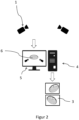
- figure 2 shows in a schematic way the calibration of a PIV measuring arrangement according to the invention. It is in the upper area of figure 2 the PIV measurement arrangement analogous to figure 1 shown. In contrast to the prior art, no calibration plate is required. Instead, a computer system is required which is figure 1 shown schematically and denoted by 4. Such a computer system is usually required anyway to carry out a PIV measurement. The computer system is used to create a three-dimensional computer model of the PIV measurement arrangement, which is indicated in the computer system's monitor and designated 5 . A calibration plate, denoted by 6, is also part of the computer model. Since this calibration plate 6 has no real counterpart, it is a virtual calibration plate 6.
- the virtual calibration plate 6 is designed and arranged within the computer model like the real calibration plate 3 in the calibration according to the prior art.
- the three-dimensional computer model 5 with the virtual calibration plate 6 can be generated using standard CAD programs, for example.
- Such a model (without the virtual calibration plate 6) is required in many cases anyway for planning and carrying out a PIV measurement.
- the additional effort for this step of the method according to the invention is kept within narrow limits.
- the images of the cameras 1 are now generated artificially using a ray tracing method, ie using photorealistic rendering and taking into account the respective material properties of the scenery.
- the calibration carried out with the artificially generated images is initially referred to as a rough calibration, since this can still be error-prone.
- the sources of error are positioning differences between real and artificial cameras with regard to the position of the artificial calibration plate.
- material inhomogeneities and manufacturing tolerances can lead to deviations between the artificially generated images and the real recordings. It should be noted that even with the conventional method using real recordings, there is a possibility of error. For example, the exact positioning of the calibration plate is very important. In any case, these errors are minimized or eliminated by further calibration steps following the rough calibration.
- FIG 3 shows the flow chart of the method according to the invention for calibrating a PIV measuring arrangement.
- the method according to the invention comprises three steps, which are denoted by V1, V2 and V3.
- V1 a PIV measurement arrangement is provided.
- V2 a computer system is provided and a three-dimensional computer model of the PIV measurement arrangement is created with the aid of the computer system, with the computer model additionally including a virtual calibration plate, which is arranged in such a way that it is in the field of view of the cameras of the PIV measurement arrangement.
- the images of the cameras are generated artificially based on the computer model using a ray tracing method.
- step V3 can only take place after step V2.
- the artificially generated images generated in step V3 can be used for the rough calibration and further calibration steps, which are known from the prior art.
Landscapes
- Engineering & Computer Science (AREA)
- Physics & Mathematics (AREA)
- General Physics & Mathematics (AREA)
- Electromagnetism (AREA)
- Computer Networks & Wireless Communication (AREA)
- Radar, Positioning & Navigation (AREA)
- Remote Sensing (AREA)
- Aviation & Aerospace Engineering (AREA)
- Computer Vision & Pattern Recognition (AREA)
- Theoretical Computer Science (AREA)
- Multimedia (AREA)
- Length Measuring Devices By Optical Means (AREA)
Description
- Die vorliegende Erfindung betrifft ein Verfahren zur Kalibrierung einer PIV Messanordnung.
- Mit Hilfe des PIV Messverfahrens ("Particle Image Velocimetry") können die Strömungsverhältnisse eines Gases oder eines anderen Fluids, wie z.B. Wasser, im dreidimensionalen Raum ermittelt werden. Eine PIV Messanordnung umfasst dabei eine Lichtquelle und wenigstens zwei Kameras. Als Lichtquelle dient meistens ein Laser, wobei die Lichtquelle bei der Durchführung einer Messung zum Einsatz kommt. In das Fluid werden Partikel beigegeben, die der Strömung folgen. Die Beobachtung der Partikelpositionen zu zwei Zeitpunkten aus unterschiedlichen Blickwinkeln, ermöglicht es, Geschwindigkeiten zu berechnen. Vor der Durchführung einer Messung muss die Messanordnung kalibriert werden, um eine eindeutige Zuordnung von Bildkoordinaten zu physikalischen Koordinaten zu ermöglichen. Für die Kalibrierung wird gewöhnlich eine Kalibrierplatte mit einer Vielzahl von Markierungen mit bekannter räumlicher Lage verwendet, welche in der Messanordnung an geeigneter Stelle angebracht wird. Nun werden mit den Kameras Kalibrieraufnahmen von der Kalibrierplatte erzeugt, welche für die Grob- bzw. vorläufige Kalibrierung verwendet werden. Nach der Grobkalibrierung erfolgen gewöhnlich weitere Kalibrierungsschritte, wie z.B. eine Selbstkalibrierung. Verfahren zur Kalibrierung einer PIV Messanordnung sind aus dem Stand der Technik bekannt. Es sei beispielhaft auf die
WO 2018/207032 A1 und dieEP 1 460 433 A2 und dieCN 109 166 154 A verwiesen. - Da der Aufwand für die beschriebene Grobkalibrierung hoch ist, wurden Verfahren zur Kalibrierung vorgeschlagen, bei denen keine Kalibrierplatte benötigt wird. Hierzu sei wiederum auf die
EP 1 460 433 A2 verwiesen. - Der Erfinder hat sich die Aufgabe gestellt, ein alternatives Verfahren zur Kalibrierung einer PIV Messanordnung anzugeben, bei dem keine Kalibrierplatte benötigt wird und das sich durch geringen Aufwand auszeichnet.
- Die gestellte Aufgabe wird durch ein Verfahren mit den Merkmalen des unabhängigen Anspruchs gelöst. Vorteilhafte Ausführungsformen ergeben sich aus den davon abhängigen Unteransprüchen.
- Die erfindungsgemäße Lösung wird nachfolgend anhand von Figuren erläutert. Darin ist im Einzelnen folgendes dargestellt:
- Figur 1
- Kalibrierung einer PIV Messanordnung gemäß dem Stand der Technik;
- Figur 2
- Erfindungsgemäße Kalibrierung einer PIV Messanordnung;
- Figur 3
- Ablaufdiagramm des erfindungsgemäßen Verfahrens zur Kalibrierung einer PIV Messanordnung.
-
Figur 1 zeigt in schematischer Weise die Kalibrierung einer PIV Messanordnung gemäß dem Stand der Technik. Die PIV Messanordnung umfasst dabei wenigstens zwei Kameras, von denen eine mit 1 bezeichnet ist. Zu einer PIV Messanordnung gehört selbstverständlich immer auch eine sogenannte Szenerie, d.h. der zu untersuchendende von einem Medium durchströmte Bereich und ggf. diesen begrenzende Glasflächen, Wände zur Begrenzung des Szenerie in der Tiefe und u.U. auch andere Bereiche, die an den zu untersuchenden Bereich angrenzen. Wenn im Folgenden von einer PIV Messanordnung gesprochen wird, so wird immer auch die Szenerie mitverstanden, ohne dass das explizit erwähnt wird. Zur Kalibrierung der PIV Messanordnung, wird eine Kalibrierplatte so angeordnet, dass sie sich im Blickfeld der Kameras 1 befindet. InFigur 1 ist die Kalibrierplatte mit 3 bezeichnet. Dann werden Bilder mit den Kameras 1 aufgenommen. Die resultierenden Aufnahmen sind inFigur 1 unterhalb den Kameras 1 dargestellt, wobei eine der Aufnahmen mit 4 bezeichnet ist. Es sei noch erwähnt, dass je nach den vorliegenden Lichtverhältnissen für die Erzeugung der Kalibrieraufnahmen eine zusätzliche Lichtquelle zum Einsatz kommen kann (oder auch nicht, falls das Umgebungslicht hierzu ausreicht). Der oben erwähnte Laser, welcher für die Durchführung der eigentlichen Messung verwendet wird, ist dazu in der Regel nicht geeignet. -
Figur 2 zeigt in schematischer Weise die erfindungsgemäße Kalibrierung einer PIV Messanordnung. Dabei ist im oberen Bereich vonFigur 2 die PIV Messanordnung analog zuFigur 1 dargestellt. Im Gegensatz zum Stand der Technik, wird keine Kalibrierplatte benötigt. Stattdessen wird ein Computersystem benötigt, welches inFigur 1 schematisch dargestellt und mit 4 bezeichnet ist. Ein solches Computersystem wird in der Regel für die Durchführung einer PIV Messung ohnehin benötigt. Das Computersystem wir dazu verwendet, um ein dreidimensionales Computermodell der PIV Messanordnung zu erstellen, welches im Monitor des Computersystems angedeutet ist und mit 5 bezeichnet ist. Teil des Computermodells ist auch eine Kalibrierplatte, welche mit 6 bezeichnet ist. Da diese Kalibrierplatte 6 kein reales Gegenstück besitzt, handelt es sich um eine virtuelle Kalibrierplatte 6. Die virtuelle Kalibrierplatte 6 ist dabei innerhalb des Computermodells so ausführt und angeordnet, wie die reale Kalibrierplatte 3 bei der Kalibrierung gemäß dem Stand der Technik. Das dreidimensionale Computermodell 5 mit virtueller Kalibrierplatte 6 kann beispielsweise mit Hilfe von gängigen CAD-Programmen erzeugt werden. Ein solches Modell (ohne die virtuelle Kalibrierplatte 6) wird in vielen Fällen ohnehin für die Planung und Durchführung einer PIV Messung benötigt. Dadurch hält sich der Mehraufwand für diesen Schritt des erfindungsgemäßen Verfahrens in engen Grenzen. Basierend auf dem dreidimensionalen Computermodell 5 samt virtueller Kalibrierplatte 6 werden nun mit Hilfe eines Raytracing-Verfahrens, d.h. mit Hilfe von fotorealistischem Rendering und unter Beachtung der jeweiligen Materialeigenschaften der Szenerie die Bilder der Kameras 1 künstlich erzeugt. Dies kann mit Hilfe des Computersystems 4 oder auch auf anderen Rechnern durchgeführt werden, und ist inFigur 2 im unteren Teil angedeutet, wobei eines der Bilder wiederum mit 3 bezeichnet ist. Im Optimalfall werden die auf diese Weise künstlich erzeugten Bilder 3 genau das wiedergeben, was die Aufnahmen der Kameras 1 gemäß dem herkömmlichen Kalibrierverfahren zeigen würden. Im weiteren Kalibrierverfahren werden die durch das erfindungsgemäße Verfahren künstlich erzeugten Bilder 3 genauso verwendet, wie die gemäß dem herkömmlichen Verfahren erzeugten Aufnahmen. - Die mit den künstlich erzeugten Bildern durchgeführte Kalibrierung wird zunächst als Grobkalibrierung bezeichnet, da diese noch fehlerbehaftet sein kann. Die Fehlerquellen bestehen in Positionierungsunterschieden zwischen realen und künstlichen Kameras in Bezug auf die Lage der künstlichen Kalibrierplatte. Weiterhin können Materialinhomogenitäten und Fertigungstoleranzen zu Abweichungen zwischen den künstlich erzeugten Bildern und den realen Aufnahmen führen. Dabei ist anzumerken, dass auch beim herkömmlichen Verfahren mit den realen Aufnahmen Fehlermöglichkeiten bestehen. So ist z.B. die genaue Positionierung der Kalibrierplatte sehr wichtig. In jedem Fall werden diese Fehler durch auf die Grobkalibrierung folgende weitere Kalibrierschritte minimiert bzw. eliminiert.
-
Figur 3 zeigt das Ablaufdiagramm des erfindungsgemäßen Verfahrens zur Kalibrierung einer PIV Messanordnung. Das erfindungsgemäße Verfahren umfasst dabei drei Schritte, welche mit V1, V2 und V3 bezeichnet sind. Im ersten Schritt V1 werden dabei eine PIV Messanordnung bereitgestellt. Im zweiten Schritt V2 wird ein Computersystem bereitgestellt und mit Hilfe des Computersystems ein dreidimensionales Computermodell der PIV Messanordnung erstellt, wobei das Computermodell zusätzlich eine virtuelle Kalibrierplatte umfasst, welche so angeordnet ist, dass sie sich im Blickfeld der Kameras der PIV Messanordnung befindet. Im dritten Schritt V3 werden basierend auf dem Computermodell mit Hilfe eines Raytracing-Verfahrens die Bilder der Kameras künstlich erzeugt. Hinsichtlich der Reihenfolge der Schritte V1 bis V3 ist zu erwähnen, dass die Schritte in der genannten Reihenfolge ausgeführt werden können. Es ist jedoch auch denkbar und vorteilhaft, wenn zuerst im Rahmen der Planung der jeweiligen PIV Messanordnung das Computermodell erzeugt wird, gemäß dem anschließend die Messanordnung bereitgestellt wird. In jedem Fall kann der Schritt V3 erst nach dem Schritt V2 erfolgen. - Wie bereits erwähnt können die im Schritt V3 erzeugten künstlich erzeugten Bilder für die Grobkalibration und weitere Kalibrationsschritte verwendet werden, welche aus dem Stand der Technik bekannt sind.
- Aus dem Gesagten ist klar, dass das erfindungsgemäße Verfahren keine reale Kalibrierplatte benötigt. Durch die Verwendung von gängigen Modellierungs- und Raytracing-Rechenverfahren hält sich der Aufwand für die Durchführung in engen Grenzen.
Claims (6)
- Verfahren zur Kalibrierung einer PIV Messanordnung, wobei die Messanordnung wenigstens zwei Kameras (1) umfasst, und das Verfahren drei Schritte (V1, V2, V3) umfasst, wobei im ersten Schritt (V1) die Messanordnung bereitgestellt wird, und wobei im zweiten Schritt (V2) ein Computersystem (4) bereit gestellt und mit Hilfe des Computersystems (4) ein dreidimensionales Computermodell (5) der Messanordnung erstellt wird, dadurch gekennzeichnet, dass das Computermodell (5) eine virtuelle Kalibrierplatte (6) und künstliche Kameras (1) umfasst, welche innerhalb des Computermodells (5) so angeordnet sind, dass sich die virtuelle Kalibrierplatte (6) im Blickfeld der künstlichen Kameras (1) befindet, und wobei im dritten Schritt (V3) basierend auf dem Computermodell (5) mit Hilfe eines Raytracing-Verfahrens die Bilder (3) der künstlichen Kameras (1) künstlich erzeugt und zur Kalibrierung verwendet werden, so dass keine reale Kalibrierplatte zur Kalibrierung benötigt wird.
- Verfahren nach Anspruch 1, wobei das Computermodell (5) mit Hilfe eines CAD-Rechenprogramms erzeugt wird.
- Verfahren nach Anspruch 1 oder 2, wobei das Raytracing-Verfahren mit Hilfe des Computersystems (4) durchgeführt wird.
- Verfahren nach einem der Ansprüche 1 bis 3, wobei die Schritte (V1, V2, V3) in der Reihenfolge V1, V2, V3 ausgeführt werden.
- Verfahren nach einem der Ansprüche 1 bis 3, wobei die Schritte (V1, V2, V3) in der Reihenfolge V2, V1, V3 ausgeführt werden.
- Verfahren nach einem der Ansprüche 1 bis 3, wobei die Schritte (V1, V2, V3) in der Reihenfolge V2, V3, V1 ausgeführt werden.
Applications Claiming Priority (2)
| Application Number | Priority Date | Filing Date | Title |
|---|---|---|---|
| DE102019103441.8A DE102019103441A1 (de) | 2019-02-12 | 2019-02-12 | Verfahren zur Kalibrierung einer PIV Messanordnung |
| PCT/EP2020/050774 WO2020164830A1 (de) | 2019-02-12 | 2020-01-14 | Verfahren zur kalibrierung einer piv messanordnung |
Publications (2)
| Publication Number | Publication Date |
|---|---|
| EP3924741A1 EP3924741A1 (de) | 2021-12-22 |
| EP3924741B1 true EP3924741B1 (de) | 2023-08-23 |
Family
ID=69187749
Family Applications (1)
| Application Number | Title | Priority Date | Filing Date |
|---|---|---|---|
| EP20701540.5A Active EP3924741B1 (de) | 2019-02-12 | 2020-01-14 | Verfahren zur kalibrierung einer piv messanordnung |
Country Status (3)
| Country | Link |
|---|---|
| EP (1) | EP3924741B1 (de) |
| DE (1) | DE102019103441A1 (de) |
| WO (1) | WO2020164830A1 (de) |
Families Citing this family (2)
| Publication number | Priority date | Publication date | Assignee | Title |
|---|---|---|---|---|
| CN117805434B (zh) * | 2024-03-01 | 2024-06-04 | 中国空气动力研究与发展中心低速空气动力研究所 | 用于时空演化壁面湍流边界层的spiv测量、标定装置及方法 |
| CN120235961B (zh) * | 2025-05-29 | 2025-09-02 | 浙江理工大学 | 基于精细定位板相机复位的piv多次标定装置及方法 |
Family Cites Families (4)
| Publication number | Priority date | Publication date | Assignee | Title |
|---|---|---|---|---|
| DE10312696B3 (de) * | 2003-03-21 | 2004-12-23 | Lavision Gmbh | Verfahren zur Bestimmung der Abbildungsgleichung für die Selbstkalibrierung in Bezug auf die Durchführung von Stereo-PIV-Verfahren |
| US10176554B2 (en) * | 2015-10-05 | 2019-01-08 | Google Llc | Camera calibration using synthetic images |
| US10186051B2 (en) | 2017-05-11 | 2019-01-22 | Dantec Dynamics A/S | Method and system for calibrating a velocimetry system |
| CN109166154B (zh) * | 2018-08-29 | 2020-09-04 | 上海交通大学 | 用于光场三维粒子图像重构的光场相机校准方法 |
-
2019
- 2019-02-12 DE DE102019103441.8A patent/DE102019103441A1/de active Pending
-
2020
- 2020-01-14 WO PCT/EP2020/050774 patent/WO2020164830A1/de not_active Ceased
- 2020-01-14 EP EP20701540.5A patent/EP3924741B1/de active Active
Also Published As
| Publication number | Publication date |
|---|---|
| DE102019103441A1 (de) | 2020-08-13 |
| EP3924741A1 (de) | 2021-12-22 |
| WO2020164830A1 (de) | 2020-08-20 |
Similar Documents
| Publication | Publication Date | Title |
|---|---|---|
| DE102005058081B4 (de) | Verfahren zur Rekonstruktion von Böen und Strukturlasten bei Flugzeugen, insbesondere Verkehrsflugzeugen | |
| EP2753897B1 (de) | Verfahren und vorrichtung zum erkennen von abweichungen einer oberfläche eines objekts | |
| DE102005061952A1 (de) | Verfahren und System zur Bestimmung einer Ungenauigkeitsinformation in einem Augmented Reality System | |
| EP2019283A2 (de) | Verfahren und Vorrichtung zur Vermessung von Ist-Messdaten eines Bauteils | |
| EP3786745B1 (de) | Identifikation von abweichungen zwischen realer anlage und ihrem digitalen zwilling | |
| DE102010039246A1 (de) | Verfahren zum Kalibrieren eines Messsystems und Vorrichtung zum Durchführen des Verfahrens | |
| EP3924741B1 (de) | Verfahren zur kalibrierung einer piv messanordnung | |
| DE102014115336A1 (de) | Verfahren zur Bestimmung eines lokalen Brechwerts und Vorrichtung hierfür | |
| DE102019203796A1 (de) | Verfahren zum Bestimmen von zu reparierenden Bereichen eines additiv hergestellten Bauelements | |
| DE102008016025A1 (de) | Verfahren und Messsystem zum Charakterisieren einer Abweichung eines Istmaßes eines Bauteils von einem Nennmaß des Bauteils | |
| EP3751261A1 (de) | Verfahren und vorrichtung zum kalibrieren eines röntgensystems | |
| DE19646702A1 (de) | Verfahren zum Detektieren von Produktionsfehlern in einem Artikel | |
| EP4016061B1 (de) | Verfahren zur bedienung eines röntgen-systems | |
| WO2019185079A1 (de) | 3-d-objekt-erfassungssystem | |
| DE102018214307A1 (de) | System und Verfahren zur Qualitätsprüfung bei der Herstellung von Einzelteilen | |
| DE102019113500B4 (de) | Verfahren zum digitalen Wuchten eines Rotors | |
| EP3992620A1 (de) | Computerimplementiertes verfahren zur ermittlung mindestens eines für eine auswertung von messdaten benötigten geometrischen parameters | |
| WO2020216840A1 (de) | Verfahren zur bereitstellung eines visuellen feedbacks | |
| EP3602021A1 (de) | Verfahren und vorrichtung zur bestimmung von mindestens zwei durchstrahlungspositionen | |
| DE102005010225A1 (de) | Verfahren zum Vergleich eines realen Gegenstandes mit einem digitalen Modell | |
| DE102005023650B4 (de) | Verfahren und Vorrichtung zur Simulation eines Bewegungsablaufs | |
| DE102013018364A1 (de) | Verfahren zur Detektion und/oder Messung von Oberflächenfehlern eines Bauteils | |
| DE10141325A1 (de) | Verfahren zur Strömungssimulation von Medien in einem Raumvolumen | |
| DE10047928A1 (de) | Simulationsverfahren | |
| WO2022053095A1 (de) | Verfahren zum prüfen von bauteilen |
Legal Events
| Date | Code | Title | Description |
|---|---|---|---|
| STAA | Information on the status of an ep patent application or granted ep patent |
Free format text: STATUS: UNKNOWN |
|
| STAA | Information on the status of an ep patent application or granted ep patent |
Free format text: STATUS: THE INTERNATIONAL PUBLICATION HAS BEEN MADE |
|
| PUAI | Public reference made under article 153(3) epc to a published international application that has entered the european phase |
Free format text: ORIGINAL CODE: 0009012 |
|
| STAA | Information on the status of an ep patent application or granted ep patent |
Free format text: STATUS: REQUEST FOR EXAMINATION WAS MADE |
|
| 17P | Request for examination filed |
Effective date: 20210913 |
|
| AK | Designated contracting states |
Kind code of ref document: A1 Designated state(s): AL AT BE BG CH CY CZ DE DK EE ES FI FR GB GR HR HU IE IS IT LI LT LU LV MC MK MT NL NO PL PT RO RS SE SI SK SM TR |
|
| DAV | Request for validation of the european patent (deleted) | ||
| DAX | Request for extension of the european patent (deleted) | ||
| GRAP | Despatch of communication of intention to grant a patent |
Free format text: ORIGINAL CODE: EPIDOSNIGR1 |
|
| STAA | Information on the status of an ep patent application or granted ep patent |
Free format text: STATUS: GRANT OF PATENT IS INTENDED |
|
| GRAS | Grant fee paid |
Free format text: ORIGINAL CODE: EPIDOSNIGR3 |
|
| GRAA | (expected) grant |
Free format text: ORIGINAL CODE: 0009210 |
|
| STAA | Information on the status of an ep patent application or granted ep patent |
Free format text: STATUS: THE PATENT HAS BEEN GRANTED |
|
| RIC1 | Information provided on ipc code assigned before grant |
Ipc: G01S 7/497 20060101ALI20230621BHEP Ipc: G06T 7/80 20170101ALI20230621BHEP Ipc: G01S 17/58 20060101ALI20230621BHEP Ipc: G01P 5/26 20060101ALI20230621BHEP Ipc: G01P 5/20 20060101ALI20230621BHEP Ipc: G01P 21/02 20060101AFI20230621BHEP |
|
| INTG | Intention to grant announced |
Effective date: 20230706 |
|
| AK | Designated contracting states |
Kind code of ref document: B1 Designated state(s): AL AT BE BG CH CY CZ DE DK EE ES FI FR GB GR HR HU IE IS IT LI LT LU LV MC MK MT NL NO PL PT RO RS SE SI SK SM TR |
|
| REG | Reference to a national code |
Ref country code: GB Ref legal event code: FG4D Free format text: NOT ENGLISH |
|
| REG | Reference to a national code |
Ref country code: CH Ref legal event code: EP |
|
| REG | Reference to a national code |
Ref country code: DE Ref legal event code: R096 Ref document number: 502020004848 Country of ref document: DE |
|
| REG | Reference to a national code |
Ref country code: IE Ref legal event code: FG4D Free format text: LANGUAGE OF EP DOCUMENT: GERMAN |
|
| REG | Reference to a national code |
Ref country code: LT Ref legal event code: MG9D |
|
| REG | Reference to a national code |
Ref country code: NL Ref legal event code: MP Effective date: 20230823 |
|
| PG25 | Lapsed in a contracting state [announced via postgrant information from national office to epo] |
Ref country code: GR Free format text: LAPSE BECAUSE OF FAILURE TO SUBMIT A TRANSLATION OF THE DESCRIPTION OR TO PAY THE FEE WITHIN THE PRESCRIBED TIME-LIMIT Effective date: 20231124 |
|
| PG25 | Lapsed in a contracting state [announced via postgrant information from national office to epo] |
Ref country code: IS Free format text: LAPSE BECAUSE OF FAILURE TO SUBMIT A TRANSLATION OF THE DESCRIPTION OR TO PAY THE FEE WITHIN THE PRESCRIBED TIME-LIMIT Effective date: 20231223 |
|
| PG25 | Lapsed in a contracting state [announced via postgrant information from national office to epo] |
Ref country code: SE Free format text: LAPSE BECAUSE OF FAILURE TO SUBMIT A TRANSLATION OF THE DESCRIPTION OR TO PAY THE FEE WITHIN THE PRESCRIBED TIME-LIMIT Effective date: 20230823 Ref country code: RS Free format text: LAPSE BECAUSE OF FAILURE TO SUBMIT A TRANSLATION OF THE DESCRIPTION OR TO PAY THE FEE WITHIN THE PRESCRIBED TIME-LIMIT Effective date: 20230823 Ref country code: PT Free format text: LAPSE BECAUSE OF FAILURE TO SUBMIT A TRANSLATION OF THE DESCRIPTION OR TO PAY THE FEE WITHIN THE PRESCRIBED TIME-LIMIT Effective date: 20231226 Ref country code: NO Free format text: LAPSE BECAUSE OF FAILURE TO SUBMIT A TRANSLATION OF THE DESCRIPTION OR TO PAY THE FEE WITHIN THE PRESCRIBED TIME-LIMIT Effective date: 20231123 Ref country code: NL Free format text: LAPSE BECAUSE OF FAILURE TO SUBMIT A TRANSLATION OF THE DESCRIPTION OR TO PAY THE FEE WITHIN THE PRESCRIBED TIME-LIMIT Effective date: 20230823 Ref country code: LV Free format text: LAPSE BECAUSE OF FAILURE TO SUBMIT A TRANSLATION OF THE DESCRIPTION OR TO PAY THE FEE WITHIN THE PRESCRIBED TIME-LIMIT Effective date: 20230823 Ref country code: LT Free format text: LAPSE BECAUSE OF FAILURE TO SUBMIT A TRANSLATION OF THE DESCRIPTION OR TO PAY THE FEE WITHIN THE PRESCRIBED TIME-LIMIT Effective date: 20230823 Ref country code: IS Free format text: LAPSE BECAUSE OF FAILURE TO SUBMIT A TRANSLATION OF THE DESCRIPTION OR TO PAY THE FEE WITHIN THE PRESCRIBED TIME-LIMIT Effective date: 20231223 Ref country code: HR Free format text: LAPSE BECAUSE OF FAILURE TO SUBMIT A TRANSLATION OF THE DESCRIPTION OR TO PAY THE FEE WITHIN THE PRESCRIBED TIME-LIMIT Effective date: 20230823 Ref country code: GR Free format text: LAPSE BECAUSE OF FAILURE TO SUBMIT A TRANSLATION OF THE DESCRIPTION OR TO PAY THE FEE WITHIN THE PRESCRIBED TIME-LIMIT Effective date: 20231124 Ref country code: FI Free format text: LAPSE BECAUSE OF FAILURE TO SUBMIT A TRANSLATION OF THE DESCRIPTION OR TO PAY THE FEE WITHIN THE PRESCRIBED TIME-LIMIT Effective date: 20230823 |
|
| PG25 | Lapsed in a contracting state [announced via postgrant information from national office to epo] |
Ref country code: PL Free format text: LAPSE BECAUSE OF FAILURE TO SUBMIT A TRANSLATION OF THE DESCRIPTION OR TO PAY THE FEE WITHIN THE PRESCRIBED TIME-LIMIT Effective date: 20230823 |
|
| PG25 | Lapsed in a contracting state [announced via postgrant information from national office to epo] |
Ref country code: ES Free format text: LAPSE BECAUSE OF FAILURE TO SUBMIT A TRANSLATION OF THE DESCRIPTION OR TO PAY THE FEE WITHIN THE PRESCRIBED TIME-LIMIT Effective date: 20230823 |
|
| PG25 | Lapsed in a contracting state [announced via postgrant information from national office to epo] |
Ref country code: SM Free format text: LAPSE BECAUSE OF FAILURE TO SUBMIT A TRANSLATION OF THE DESCRIPTION OR TO PAY THE FEE WITHIN THE PRESCRIBED TIME-LIMIT Effective date: 20230823 Ref country code: RO Free format text: LAPSE BECAUSE OF FAILURE TO SUBMIT A TRANSLATION OF THE DESCRIPTION OR TO PAY THE FEE WITHIN THE PRESCRIBED TIME-LIMIT Effective date: 20230823 Ref country code: ES Free format text: LAPSE BECAUSE OF FAILURE TO SUBMIT A TRANSLATION OF THE DESCRIPTION OR TO PAY THE FEE WITHIN THE PRESCRIBED TIME-LIMIT Effective date: 20230823 Ref country code: EE Free format text: LAPSE BECAUSE OF FAILURE TO SUBMIT A TRANSLATION OF THE DESCRIPTION OR TO PAY THE FEE WITHIN THE PRESCRIBED TIME-LIMIT Effective date: 20230823 Ref country code: DK Free format text: LAPSE BECAUSE OF FAILURE TO SUBMIT A TRANSLATION OF THE DESCRIPTION OR TO PAY THE FEE WITHIN THE PRESCRIBED TIME-LIMIT Effective date: 20230823 Ref country code: CZ Free format text: LAPSE BECAUSE OF FAILURE TO SUBMIT A TRANSLATION OF THE DESCRIPTION OR TO PAY THE FEE WITHIN THE PRESCRIBED TIME-LIMIT Effective date: 20230823 Ref country code: SK Free format text: LAPSE BECAUSE OF FAILURE TO SUBMIT A TRANSLATION OF THE DESCRIPTION OR TO PAY THE FEE WITHIN THE PRESCRIBED TIME-LIMIT Effective date: 20230823 |
|
| REG | Reference to a national code |
Ref country code: DE Ref legal event code: R097 Ref document number: 502020004848 Country of ref document: DE |
|
| PG25 | Lapsed in a contracting state [announced via postgrant information from national office to epo] |
Ref country code: IT Free format text: LAPSE BECAUSE OF FAILURE TO SUBMIT A TRANSLATION OF THE DESCRIPTION OR TO PAY THE FEE WITHIN THE PRESCRIBED TIME-LIMIT Effective date: 20230823 |
|
| PLBE | No opposition filed within time limit |
Free format text: ORIGINAL CODE: 0009261 |
|
| STAA | Information on the status of an ep patent application or granted ep patent |
Free format text: STATUS: NO OPPOSITION FILED WITHIN TIME LIMIT |
|
| 26N | No opposition filed |
Effective date: 20240524 |
|
| PG25 | Lapsed in a contracting state [announced via postgrant information from national office to epo] |
Ref country code: SI Free format text: LAPSE BECAUSE OF FAILURE TO SUBMIT A TRANSLATION OF THE DESCRIPTION OR TO PAY THE FEE WITHIN THE PRESCRIBED TIME-LIMIT Effective date: 20230823 |
|
| PG25 | Lapsed in a contracting state [announced via postgrant information from national office to epo] |
Ref country code: MC Free format text: LAPSE BECAUSE OF FAILURE TO SUBMIT A TRANSLATION OF THE DESCRIPTION OR TO PAY THE FEE WITHIN THE PRESCRIBED TIME-LIMIT Effective date: 20230823 |
|
| PG25 | Lapsed in a contracting state [announced via postgrant information from national office to epo] |
Ref country code: MC Free format text: LAPSE BECAUSE OF FAILURE TO SUBMIT A TRANSLATION OF THE DESCRIPTION OR TO PAY THE FEE WITHIN THE PRESCRIBED TIME-LIMIT Effective date: 20230823 |
|
| PG25 | Lapsed in a contracting state [announced via postgrant information from national office to epo] |
Ref country code: LU Free format text: LAPSE BECAUSE OF NON-PAYMENT OF DUE FEES Effective date: 20240114 |
|
| GBPC | Gb: european patent ceased through non-payment of renewal fee |
Effective date: 20240114 |
|
| PG25 | Lapsed in a contracting state [announced via postgrant information from national office to epo] |
Ref country code: LU Free format text: LAPSE BECAUSE OF NON-PAYMENT OF DUE FEES Effective date: 20240114 |
|
| PG25 | Lapsed in a contracting state [announced via postgrant information from national office to epo] |
Ref country code: GB Free format text: LAPSE BECAUSE OF NON-PAYMENT OF DUE FEES Effective date: 20240114 |
|
| PG25 | Lapsed in a contracting state [announced via postgrant information from national office to epo] |
Ref country code: BE Free format text: LAPSE BECAUSE OF NON-PAYMENT OF DUE FEES Effective date: 20240131 |
|
| PG25 | Lapsed in a contracting state [announced via postgrant information from national office to epo] |
Ref country code: GB Free format text: LAPSE BECAUSE OF NON-PAYMENT OF DUE FEES Effective date: 20240114 Ref country code: BE Free format text: LAPSE BECAUSE OF NON-PAYMENT OF DUE FEES Effective date: 20240131 |
|
| REG | Reference to a national code |
Ref country code: BE Ref legal event code: MM Effective date: 20240131 |
|
| PG25 | Lapsed in a contracting state [announced via postgrant information from national office to epo] |
Ref country code: BG Free format text: LAPSE BECAUSE OF FAILURE TO SUBMIT A TRANSLATION OF THE DESCRIPTION OR TO PAY THE FEE WITHIN THE PRESCRIBED TIME-LIMIT Effective date: 20230823 |
|
| PG25 | Lapsed in a contracting state [announced via postgrant information from national office to epo] |
Ref country code: BG Free format text: LAPSE BECAUSE OF FAILURE TO SUBMIT A TRANSLATION OF THE DESCRIPTION OR TO PAY THE FEE WITHIN THE PRESCRIBED TIME-LIMIT Effective date: 20230823 |
|
| PG25 | Lapsed in a contracting state [announced via postgrant information from national office to epo] |
Ref country code: IE Free format text: LAPSE BECAUSE OF NON-PAYMENT OF DUE FEES Effective date: 20240114 |
|
| PG25 | Lapsed in a contracting state [announced via postgrant information from national office to epo] |
Ref country code: IE Free format text: LAPSE BECAUSE OF NON-PAYMENT OF DUE FEES Effective date: 20240114 |
|
| PG25 | Lapsed in a contracting state [announced via postgrant information from national office to epo] |
Ref country code: CY Free format text: LAPSE BECAUSE OF FAILURE TO SUBMIT A TRANSLATION OF THE DESCRIPTION OR TO PAY THE FEE WITHIN THE PRESCRIBED TIME-LIMIT; INVALID AB INITIO Effective date: 20200114 |
|
| PG25 | Lapsed in a contracting state [announced via postgrant information from national office to epo] |
Ref country code: HU Free format text: LAPSE BECAUSE OF FAILURE TO SUBMIT A TRANSLATION OF THE DESCRIPTION OR TO PAY THE FEE WITHIN THE PRESCRIBED TIME-LIMIT; INVALID AB INITIO Effective date: 20200114 |
|
| PG25 | Lapsed in a contracting state [announced via postgrant information from national office to epo] |
Ref country code: TR Free format text: LAPSE BECAUSE OF FAILURE TO SUBMIT A TRANSLATION OF THE DESCRIPTION OR TO PAY THE FEE WITHIN THE PRESCRIBED TIME-LIMIT Effective date: 20230823 |
|
| REG | Reference to a national code |
Ref country code: CH Ref legal event code: U11 Free format text: ST27 STATUS EVENT CODE: U-0-0-U10-U11 (AS PROVIDED BY THE NATIONAL OFFICE) Effective date: 20260201 |
|
| PGFP | Annual fee paid to national office [announced via postgrant information from national office to epo] |
Ref country code: DE Payment date: 20260121 Year of fee payment: 7 |
|
| PGFP | Annual fee paid to national office [announced via postgrant information from national office to epo] |
Ref country code: AT Payment date: 20260122 Year of fee payment: 7 |
|
| PGFP | Annual fee paid to national office [announced via postgrant information from national office to epo] |
Ref country code: FR Payment date: 20260123 Year of fee payment: 7 |
|
| PGFP | Annual fee paid to national office [announced via postgrant information from national office to epo] |
Ref country code: CH Payment date: 20260201 Year of fee payment: 7 |