EP3925096B1 - Prise en charge de système 5g pour la gestion de pont de tsn virtuel, le mappage de qos et la planification de qbv de tsn - Google Patents
Prise en charge de système 5g pour la gestion de pont de tsn virtuel, le mappage de qos et la planification de qbv de tsn Download PDFInfo
- Publication number
- EP3925096B1 EP3925096B1 EP20708642.2A EP20708642A EP3925096B1 EP 3925096 B1 EP3925096 B1 EP 3925096B1 EP 20708642 A EP20708642 A EP 20708642A EP 3925096 B1 EP3925096 B1 EP 3925096B1
- Authority
- EP
- European Patent Office
- Prior art keywords
- tsn
- network
- bridge
- gate
- virtual
- Prior art date
- Legal status (The legal status is an assumption and is not a legal conclusion. Google has not performed a legal analysis and makes no representation as to the accuracy of the status listed.)
- Active
Links
Images


Classifications
-
- H—ELECTRICITY
- H04—ELECTRIC COMMUNICATION TECHNIQUE
- H04W—WIRELESS COMMUNICATION NETWORKS
- H04W28/00—Network traffic management; Network resource management
- H04W28/02—Traffic management, e.g. flow control or congestion control
-
- H—ELECTRICITY
- H04—ELECTRIC COMMUNICATION TECHNIQUE
- H04W—WIRELESS COMMUNICATION NETWORKS
- H04W28/00—Network traffic management; Network resource management
- H04W28/02—Traffic management, e.g. flow control or congestion control
- H04W28/0268—Traffic management, e.g. flow control or congestion control using specific QoS parameters for wireless networks, e.g. QoS class identifier [QCI] or guaranteed bit rate [GBR]
-
- H—ELECTRICITY
- H04—ELECTRIC COMMUNICATION TECHNIQUE
- H04L—TRANSMISSION OF DIGITAL INFORMATION, e.g. TELEGRAPHIC COMMUNICATION
- H04L12/00—Data switching networks
- H04L12/28—Data switching networks characterised by path configuration, e.g. LAN [Local Area Networks] or WAN [Wide Area Networks]
- H04L12/46—Interconnection of networks
- H04L12/4641—Virtual LANs, VLANs, e.g. virtual private networks [VPN]
-
- H—ELECTRICITY
- H04—ELECTRIC COMMUNICATION TECHNIQUE
- H04L—TRANSMISSION OF DIGITAL INFORMATION, e.g. TELEGRAPHIC COMMUNICATION
- H04L47/00—Traffic control in data switching networks
- H04L47/10—Flow control; Congestion control
- H04L47/24—Traffic characterised by specific attributes, e.g. priority or QoS
- H04L47/2416—Real-time traffic
-
- H—ELECTRICITY
- H04—ELECTRIC COMMUNICATION TECHNIQUE
- H04L—TRANSMISSION OF DIGITAL INFORMATION, e.g. TELEGRAPHIC COMMUNICATION
- H04L47/00—Traffic control in data switching networks
- H04L47/10—Flow control; Congestion control
- H04L47/28—Flow control; Congestion control in relation to timing considerations
- H04L47/283—Flow control; Congestion control in relation to timing considerations in response to processing delays, e.g. caused by jitter or round trip time [RTT]
-
- H—ELECTRICITY
- H04—ELECTRIC COMMUNICATION TECHNIQUE
- H04W—WIRELESS COMMUNICATION NETWORKS
- H04W76/00—Connection management
- H04W76/10—Connection setup
- H04W76/12—Setup of transport tunnels
Definitions
- the present disclosure relates to a cellular communications system and, more specifically, to a cellular communications system that operates as a virtual node in a Time-Sensitive Networking (TSN) network.
- TSN Time-Sensitive Networking
- Flexible connectivity infrastructure is a key enabler for manufacturing to interconnect machines, products, and all kinds of other devices in a flexible, secure, and consistent manner.
- the Third Generation Partnership Project (3GPP) Fifth Generation (5G) system should support new requirements and challenges coming from these vertical domains.
- 3GPP has a study on Communication for Automation in Vertical Domains (Technical Report (TR) 22.804), where many use cases from vertical domains are analyzed.
- Industrial automation applications such as motion control have extremely stringent service requirements on high availability, ultra-reliable, low latency, low jitter, and determinism, e.g., 1-10 milliseconds (ms) end-to-end latency, 1-100 microsecond ( ⁇ s) packet delay variation [2].
- TSN Time-Sensitive Networking
- IEEE 802.1 TSN standards 802.1Qbv
- IEEE 802.1Qbv can provide on-time delivery of TSN frames. It defines a means to transmit certain Ethernet frames on a time-based schedule. IEEE 802.1Qbv requires time synchronization, i.e. each bridge has to be aware of the same time.
- 5GS 5G System
- a virtual TSN node e.g., a virtual TSN bridge
- Document WO 2017/082779 A1 discloses packet processing by a network element system that transfers first and second packet flows of the same traffic handling class (e.g., the Ethernet express traffic class).
- a method aspect performed by the network element system comprises the step of receiving, from a network controller, information defining opening times for packet gates associated with network element ports. The opening times define a relative transmission order among first packet flow packets and second packet flow packets. Upon receipt of first and second packet flow packets at the respective ports, the packet gates are controlled based on the received information to trigger transmission of the first and second packet flow packets in the predefined transmission order.
- TSN Time-Sensitive Networking
- QoS Quality of Service
- TSN related scheduling in a cellular communications system such as, for example, the Fifth Generation System (5GS).
- 5GS Fifth Generation System
- Radio Node As used herein, a "radio node” is either a radio access node or a wireless device.
- Radio Access Node As used herein, a "radio access node” or “radio network node” is any node in a Radio Access Network (RAN) of a cellular communications network that operates to wirelessly transmit and/or receive signals.
- a radio access node include, but are not limited to, a base station (e.g., a New Radio (NR) base station (gNB) in a Third Generation Partnership Project (3GPP) Fifth Generation (5G) NR network or an enhanced or evolved Node B (eNB) in a 3GPP Long Term Evolution (LTE) network), a high-power or macro base station, a low-power base station (e.g., a micro base station, a pico base station, a home eNB, or the like), and a relay node.
- a base station e.g., a New Radio (NR) base station (gNB) in a Third Generation Partnership Project (3GPP) Fifth Generation (5G) NR network or an enhanced or evolved Node B (eNB)
- a "core network node” is any type of node in a core network.
- Some examples of a core network node include, e.g., a Mobility Management Entity (MME), a Packet Data Network Gateway (P-GW), a Service Capability Exposure Function (SCEF), or the like.
- MME Mobility Management Entity
- P-GW Packet Data Network Gateway
- SCEF Service Capability Exposure Function
- a “wireless device” is any type of device that has access to (i.e., is served by) a cellular communications network by wirelessly transmitting and/or receiving signals to a radio access node(s).
- a wireless device include, but are not limited to, a User Equipment device (UE) in a 3GPP network and a Machine Type Communication (MTC) device.
- UE User Equipment device
- MTC Machine Type Communication
- Network Node As used herein, a "network node” is any node that is either part of the RAN or the core network of a cellular communications network/system.
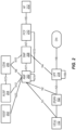
- Figure 1 illustrates one example of a cellular communications system 100 in which embodiments of the present disclosure (e.g., embodiments described herein in Sections II, III, and IV below) may be implemented.
- the cellular communications system 100 is a 5G System (5GS); however, the present disclosure is not limited thereto.
- the cellular communications system 100 includes base stations 102-1 and 102-2, which in 5G NR are referred to as gNBs, controlling corresponding macro cells 104-1 and 104-2.
- the base stations 102-1 and 102-2 are generally referred to herein collectively as base stations 102 and individually as base station 102.
- the macro cells 104-1 and 104-2 are generally referred to herein collectively as macro cells 104 and individually as macro cell 104.
- the cellular communications system 100 may also include a number of low power nodes 106-1 through 106-4 controlling corresponding small cells 108-1 through 108-4.
- the low power nodes 106-1 through 106-4 can be small base stations (such as pico or femto base stations) or Remote Radio Heads (RRHs), or the like.
- RRHs Remote Radio Heads
- the low power nodes 106-1 through 106-4 are generally referred to herein collectively as low power nodes 106 and individually as low power node 106.
- the small cells 108-1 through 108-4 are generally referred to herein collectively as small cells 108 and individually as small cell 108.
- the base stations 102 (and optionally the low power nodes 106) are connected to a core network 110.
- the core network 110 is a 5G Core (5GC).
- the base stations 102 and the low power nodes 106 provide service to wireless devices 112-1 through 112-5 in the corresponding cells 104 and 108.
- the wireless devices 112-1 through 112-5 are generally referred to herein collectively as wireless devices 112 and individually as wireless device 112.
- the wireless devices 112 are also sometimes referred to herein as UEs.
- the core network 110 e.g., 5GC
- the core network 110 e.g., 5GC
- This controller typically includes a Centralized Network Configuration (CNC) station, which configures the network resource reservations and is responsible for coordinating any changes to those configured reservations with any new reservations. Reservations can be made or requested by end stations.
- CNC Centralized Network Configuration
- the CNC station receives the requirements of the data flows from a Central User Configuration (CUC) entity and then computes the route, the time schedules needed for the end-to-end transmission for each TSN flow, and configures the TSN bridges with the computed time schedule.
- CRC Central User Configuration
- the CNC is communicatively coupled to the core network 110 (e.g., the 5GC).
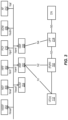
- Figure 2 illustrates a wireless communication system represented as a 5G network architecture composed of core Network Functions (NFs), where interaction between any two NFs is represented by a point-to-point reference point/interface.
- Figure 2 can be viewed as one particular implementation of the system 100 of Figure 1 .
- NFs Network Functions
- the 5G network architecture shown in Figure 2 comprises a plurality of UEs 112 connected to either a RAN 102 or an Access Network (AN) as well as an Access and Mobility Management Function (AMF) 200.
- the R(AN) 102 comprises base stations, e.g. such as eNBs or gNBs or similar.
- the 5G core NFs shown in Figure 2 include a Network Slice Selection Function (NSSF) 202, an Authentication Server Function (AUSF) 204, a Unified Data Management (UDM) 206, the AMF 200, a Session Management Function (SMF) 208, a Policy Control Function (PCF) 210, and an Application Function (AF) 212.
- NSSF Network Slice Selection Function
- AUSF Authentication Server Function
- UDM Unified Data Management
- SMF Session Management Function
- PCF Policy Control Function
- AF Application Function
- the N1 reference point is defined to carry signaling between the UE 112 and AMF 200.
- the reference points for connecting between the AN 102 and AMF 200 and between the AN 102 and UPF 214 are defined as N2 and N3, respectively.
- N4 is used by the SMF 208 and UPF 214 so that the UPF 214 can be set using the control signal generated by the SMF 208, and the UPF 214 can report its state to the SMF 208.
- N9 is the reference point for the connection between different UPFs 214
- N14 is the reference point connecting between different AMFs 200, respectively.
- N15 and N7 are defined since the PCF 210 applies policy to the AMF 200 and SMF 208, respectively.
- N12 is required for the AMF 200 to perform authentication of the UE 112.
- N8 and N10 are defined because the subscription data of the UE 112 is required for the AMF 200 and SMF 208.
- the 5GC network aims at separating user plane and control plane.
- the user plane carries user traffic while the control plane carries signaling in the network.
- the UPF 214 is in the user plane and all other NFs, i.e., the AMF 200, SMF 208, PCF 210, AF 212, NSSF 202, AUSF 204, and UDM 206, are in the control plane. Separating the user and control planes guarantees each plane resource to be scaled independently. It also allows UPFs to be deployed separately from control plane functions in a distributed fashion. In this architecture, UPFs may be deployed very close to UEs to shorten the Round Trip Time (RTT) between UEs and data network for some applications requiring low latency.
- RTT Round Trip Time
- the core 5G network architecture is composed of modularized functions.
- the AMF 200 and SMF 208 are independent functions in the control plane. Separated AMF 200 and SMF 208 allow independent evolution and scaling.
- Other control plane functions like the PCF 210 and AUSF 204 can be separated as shown in Figure 2 . Modularized function design enables the 5GC network to support various services flexibly.
- Each NF interacts with another NF directly. It is possible to use intermediate functions to route messages from one NF to another NF.
- a set of interactions between two NFs is defined as service so that its reuse is possible. This service enables support for modularity.
- the user plane supports interactions such as forwarding operations between different UPFs.
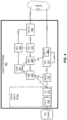
- Figure 3 illustrates a 5G network architecture using service-based interfaces between the NFs in the control plane, instead of the point-to-point reference points/interfaces used in the 5G network architecture of Figure 2 .
- the NFs described above with reference to Figure 2 correspond to the NFs shown in Figure 3 .
- the service(s) etc. that a NF provides to other authorized NFs can be exposed to the authorized NFs through the service-based interface.
- the service based interfaces are indicated by the letter "N" followed by the name of the NF, e.g. Namf for the service based interface of the AMF 200 and Nsmf for the service based interface of the SMF 208, etc.
- NEF Network Exposure Function
- NRF Network Repository Function
- the AMF 200 provides UE-based authentication, authorization, mobility management, etc.
- a UE 112 even using multiple access technologies is basically connected to a single AMF 200 because the AMF 200 is independent of the access technologies.
- the SMF 208 is responsible for session management and allocates Internet Protocol (IP) addresses to UEs. It also selects and controls the UPF 214 for data transfer. If a UE 112 has multiple sessions, different SMFs 208 may be allocated to each session to manage them individually and possibly provide different functionalities per session.
- the AF 212 provides information on the packet flow to the PCF 210 responsible for policy control in order to support Quality of Service (QoS).
- QoS Quality of Service
- the PCF 210 determines policies about mobility and session management to make the AMF 200 and SMF 208 operate properly.
- the AUSF 204 supports authentication function for UEs or similar and thus stores data for authentication of UEs or similar while the UDM 206 stores subscription data of the UE 112.
- the Data Network (DN) not part of the 5GC network, provides Internet access or operator services and similar.
- An NF may be implemented either as a network element on a dedicated hardware, as a software instance running on a dedicated hardware, or as a virtualized function instantiated on an appropriate platform, e.g., a cloud infrastructure.
- Embodiments of the present disclosure more specifically relate to the 5GS appearing as a TSN bridge for integration with a TSN.
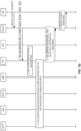
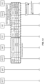
- Figure 4 which is a reproduction of Figure 4 .4.8.2-1 of Change Request (CR) S2-1906754 for 3GPP Technical Specification (TS) 23.501, shows one example of an architecture in which a 5GS appears as a TSN bridge 400.
- the architecture includes a TSN AF 402, DS-TT 404, and NW-TT 406.
- the TSN Translator (TT) at the UE-side which is denoted in Figure 4 as the DS-TT 404 and also referred to herein as UE side TT or UE/TT, is shown outside of the UE 112, and the TT at the UPF side, which is denoted in Figure 4 as NW-TT 406 and also referred to herein as UPF side TT or UPF/TT, is shown inside of the UPF 214.
- the DS-TT 404 at the UE side is alternatively implemented within the UE 112 and/or the NW-TT 406 at the UPF side is alternatively implemented outside of the UPF 214.
- IEEE 802.1Qbv The Institute for Electronics and Electrical Engineers (IEEE) 802.1Qbv standard describes enhancements for supporting scheduled traffic over a TSN domain. Proper traffic scheduling is essential for most vertical services, e.g. industry automation.
- IEEE 802.1Qbv the 3GPP 5GS virtual bridge is to perform the scheduling on its corresponding egress ports according to IEEE 802.1Qbv.
- the essence of IEEE 802.1Qbv scheduling is that the frame transmission from each queue, which is associated to a Traffic Class (TC), is scheduled relative to a known timescale.
- TC Traffic Class
- a transmission gate is associated to each queue, where the state of the transmission gate determines whether or not a queued frame can be selected for transmission.
- the transmission gate has two states: open and closed.
- a gate control list is associated with each port and contains an ordered list of gate operations. Each gate operation changes the transmission gate state for the transmission gate associated with each of the port's TC queues according to a scheduled time. The period of the time over which the sequence of gate operations in the gate control list repeats is called a "gating cycle.”
- IEEE 802.1Qbv specifies a list of parameters (i.e., a "Gate Parameter Table") that supports the enhancement of scheduled traffic.
- the CNC calculates the gate operations based on the stream characteristics and configures the transmission gates on the ports of the TSN bridges accordingly.
- 3GPP S2-1901150 "TSN QoS and traffic scheduling in 5GS” (hereinafter "S2-1901150”), output pacing with a de-jitter buffer function was proposed to perform the TSN scheduling at the egress port of the 5GS bridge.
- 3GPP Technical Report (TR) 23.734 Solution#30 (see 3GPP TR 23.734 DRAFT V16.0.0+ (20198-102): " Study on 5GS Enhanced support of Vertical and LAN Services ") proposed a procedure of how 5GS can convey the TSN traffic pattern and corresponding scheduling information from the CNC to the relevant nodes in 5GS.
- the TSN traffic pattern includes information for TSN supporting such as gate control mechanism scheduling TSN traffic, etc. This part of information is identified as additional parameters for 5GS to fulfill the QoS requirement of TSN communications, which is not included in the 5G QoS model.
- the detailed traffic scheduling parameters were not provided in 3GPP TR 23.734 Solution#30.
- This section provides an update to 3GPP TR 23.734 Solution#30.
- this section describes mechanisms to provide a minimal set of TSN traffic scheduling parameters that are needed for 5GS to perform output pacing/scheduling according to the IEEE 802.1Qbv scheduling.
- the IEEE 802.1Obv information exchange between 5GS and CNC involves two procedures:
- the UE or UE-side translator is the egress port of the 5GS, and therefore operates the IEEE 802.1Qbv gate scheduling.
- the " TickGranularity" can be passed from the UE to the TSN AF by using existing 3GPP procedures, e.g. Protocol Data Unit (PDU) session establishment/modification procedure (Option 1: SMF-NEF-AF, event notification; Option 2: SMF-PCF, session management policy modification procedure).
- PDU Protocol Data Unit
- Option 1 SMF-NEF-AF, event notification
- Option 2 SMF-PCF, session management policy modification procedure
- the UE sends the information to the AMF via Non-Access Stratum (NAS) signaling, the AMF conveys information to the SMF, and the SMF forwards it to the TSN AF via an event notification procedure.
- NAS Non-Access Stratum
- the User Plane Function (UPF) or UPF side translator performs the IEEE 802.1Qbv output pacing.
- the " TickGranularity" can be passed from the UPF to the AF by using existing 3GPP procedures, e.g. N4 session establishment/modification procedure (UPF to SMF), event notification procedure (SMF to NEF and AF).
- the ExclusiveGating parameter can be stored in the AF and linked with a bridge identifier (ID) and port ID so that the CNC can read it and then make relevant calculations and configurations later.
- ID bridge identifier
- the capability reports for TickGranularity and ExclusiveGating can also be optionally stored in the PCF.
- the SMF can propagate the information to the PCF via a Session Management Policy Modification procedure.
- the following parameters specified by IEEE 802.1Qbv shall be provided by the CNC to the 5GS, by configuring the output pacing.
- the parameters are handled by the AF and, if needed, translated for the output pacing mechanism implemented by the TSN translator.
- the translator can be either an independent unit or integrated with the UE or UPF.
- Figure 5 is used for better understanding the above parameters. Note that Figure 5 is a reproduction of a corresponding figure from the IEEE 802.1Qbv standard.
- "Gate control list” illustrates the AdminControlList with the list of gate schedule actions; e.g. T00, T01 and so on define the time when the given gate state should be changed to a new one (associated to TimeIntervalValue), then the states of the gates per TC (8 characters for the 8 TCs, o - open, C - closed) are shown (associated to GateStateValue).
- the AdminBaseTime parameter gives the absolute time when the Gate control list should be started to apply on the given port. After the final entry of the list is performed, the first list entry is applied again, according to the cyclical operation.
- the above parameters are mandatory, but enough to provide the proper operation of the output pacing mechanism.
- the entries in the AdminControlList obviously specify which queue can be served by the output pacing at a given time. Assuming that the 5GS and TSN are properly synchronized, the output pacing can determine when execution of the gating cycle shall be started.
- the AF is responsible for managing the exchanges of the above parameters between the 5GS and the CNC.
- the CNC provides the computed gate operation schedule (AdminControlList and AdminBaseTime) for a corresponding port of the 5GS virtual bridge, the AF forwards this information for the output pacing mechanism associated to the port.
- de-jitter buffers are deployed on a per TC basis.
- a de-jitter buffer belongs to a TC.
- the entries of the IEEE 802.1Qbv gate control list determine the de-jitter buffer associated to the TC whose frames could be handled by the output pacing at a given time.
- the output pacing mechanism is responsible for determining the order of the frames to be served, (e.g., First-In-First-Out (FIFO) can be applied).
- FIFO First-In-First-Out
- One option to optimize the order of servable frames based on latency occurs in the 5GS.
- the 5GS and/or the TSN Translator puts a time-stamp on the frame. This time-stamp indicates the arrival time of the frame.
- output pacing at the egress port checks the time-stamp values of the frames in the de-jitter buffer associated to the currently servable queue and selects the next frame accordingly.
- One option could be to select the frame with the largest delay across the 5GS by ensuring the minimization of the latency variance of the 5GS for each frame.
- T current- T arrived D , where D is the deterministic latency of the 5GS virtual bridge, is valid will be served. Note that T current is the current time and T arrived is the time of arrival of the frame.
- the IEEE 802.10bv standard describes enhancement for supporting scheduled traffic over a TSN domain. Proper traffic scheduling is essential for most Vertical services, e.g. Industry automation.
- 802.1Qbv is applied in the TSN domain
- the 5GS virtual bridge shall perform the scheduling on its corresponding egress ports according to the 802.1Qbv.
- the essence of 802.1Qbv scheduling is that the frame transmission from each queue (associated to a Traffic Class - TC) is scheduled relative to a known timescale.
- a transmission gate is associated to each queue; the state of the gate determines whether or not a queued frame can be selected for transmission.
- the gate has two states: open and close.
- a gate control list is associated with each port contains an ordered list of gate operations.
- Each gate operation changes the transmission gate state for the gate associated with each of the port's traffic class queues according to a scheduled time.
- the period of the time over which the sequence of gate operations in the gate control list repeats called gating cycle.
- the 802.1Qbv specifies a list of parameters (Gate Parameter Table) that supports the enhancement of scheduled traffic.
- the CNC calculates the gate operations based on the stream characteristics and configures the gates on the ports of the TSN bridges accordingly.
- the 802.1Obv information exchange between 5GS and CNC involves two procedures:
- the following parameters specified by the 802.10bv are used to explore the 5GS virtual bridge capabilities by the CNC.
- the following parameters specified by the 802.10bv shall be provided by from CNC to 5GS, by configuring the output pacing.
- the parameters are handled by the AF and if needed translated for the output pacing mechanism implemented by the TSN Translator (the translator can be either an independent unit or integrated with UE or UPF).
- the entries in the AdminControlList obviously specifies which queue can be served by the output pacing at a given time. Assuming that 5GS and TSN is properly synchronized, the output pacing can determine when execution of gating cycle shall be started.
- the figure is related to both QoS mapping and distribution of TSN scheduling information, however the description below will only be related to the distribution of TSN scheduling information.
- This section provides details on how to perform the QoS mapping while being compliant with the input and output information required in the TSN. Also, this section proposes a feedback approach in order to match the reported/exposed information to the TSN and the received configuration information from the CNC. In this way, the 5GS will configure connections internally only according to the requirements.
- 3GPP TR 23.734 Solution#18 described QoS negotiation between 3GPP and TSN networks.
- the control plane based QoS negotiation includes two stages: TSN capabilities reporting for the 5GS TSN bridge (see 3GPP TR 23.734, section 6.18.1.2.1), and "TSN-aware QoS profile generation " (see 3GPP TR 23.734, section 6.18.1.2.2).
- Solution#30 in 3GPP TR 23.734 proposed a procedure of "TSN related QoS configuration for 5G virtual bridge " which can be an alternative to the "TSN-aware QoS profile generation" (see 3GPP TR 23.734, section 6.18.1.2.2). This procedure suggested a framework to divide TSN related QoS configuration for the 5G virtual bridge into two parts:
- This section provides an update of Solution#30.
- the section provides a minimal set of TSN QoS parameters that need to be mapped to 5G QoS.
- Any TSN bridge has a set of objects, which are parameters that can be accessed by a network management entity.
- parameters can be read-only (R) or read-and-write (R/W) type.
- R read-only
- R/W read-and-write
- TSN parameter Type Description traffic-class-table R/W Each frame is mapped to a traffic class using the Traffic Class Table for the Port and the frame's priority. Structure: (a) Number of traffic classes, (b) enumeration of traffic classes, (c) respective priority (or set of priorities) per traffic class.
- adminIdleSlope from Bandwidth Availability Table
- the CNC entity can use adminIdleSlope to reserve the bandwidth, in bits per second, of the queue associated with traffic class N.
- Strict priority is the default use_DEI R/W
- the drop_eligible parameter may also (besides PCP) be encoded in and decoded from the Drop Eligible Indicator (DEI) in the VLAN tag. If the Boolean parameter use_DEI is TRUE, then it is possible to use the DEI in the VLAN tag to convey eight distinct priorities, each with a DEI. defaultPriority R/W Default priority of a queue. Modified in some special cases. Note: This parameter is used when untagged frame is received by UE being edge port. priority-regeneration-table R/W Under normal circumstances, priority is not modified in transit through the relay function of a Bridge; however, there may be some circumstances where it is desirable for management purposes to control how priority is propagated.
- the Regenerated priority is identical to the incoming priority.
- the length-dependent delay typically includes the time to receive and store each octet of the frame, which depends on the link speed of the ingress Port.
- txPropagation Delay R The transmission propagation delay along the network media for a frame transmitted from the specified Port of this station to the neighboring Port on a different station. (per port).
- the parameters may also include dependentDelayMin/Max and txPropagationDelay.
- the calculation of these parameters may be, e.g., left to the particular 5G implementation.
- "length-dependent delay attribute specifies the time for a single octet of the frame to transfer from ingress to egress".
- R parameters can be reported by any bridge to the CNC as part of TSN capabilities reporting for 5GS TSN bridge ( 3GPP S1-183120: “cyberCAV - 5G in Industrial Automation: Different and Multiple Time Domains for Synchronization", section 6.18.1.2.1 ).
- 3GPP S1-183120 "cyberCAV - 5G in Industrial Automation: Different and Multiple Time Domains for Synchronization", section 6.18.1.2.1 ).
- the direction of the information between bridges and the CNC is that the CNC reads the managed objects and the parameters.
- the bridge may indicate that there was some change in the managed object, which may trigger the CNC to read it (again).
- W parameters can be used for bridge configuration, in the context of 5GS-TSN integration, it can be part of the "TSN-aware QoS profile generation" procedure ( 3GPP TR 23.734 DRAFT V16.0.0+ (20198-102): “Study on 5GS Enhanced support of Vertical and LAN Services", section 6.18.1.2.2 ) or "TSN related QoS configuration for 5G virtual bridge” procedure in solution#30. All R/W parameters are related to both capability report and bridge configuration procedure.
- Some parameters are rarely changed, such as defaultPriority and the priority regeneration table. The latter could be necessary to adjust the 5GS virtual bridge, in the case it is at the edge of the TSN and interacting with other non-TSN-aware bridges/end stations.
- the transmission selection algorithm plays a role when more than one gate is open at the same time. Note that there is one time-gate per queue. If Strict Priority is the applied transmission selection algorithm, then the frames are selected for transmission based on their priority. If the number of TCs (declared number of queues per port) used is less than eight (maximum), then each class may map more than one priority value for frames. It is recommended to map the priority to TCs as defined in Table 8-5 of the IEEE 802.1Q standard.
- Port Control Protocol is encoded at the source bridge component where the frame is originated, and any bridge in the communication path of this frame may decode the PCP to obtain the values of priority and drop-eligibility.
- PCP Port Control Protocol
- Tables are general for the TSN system and can be used to extract information from the frame. Tables for coding and decoding are available in the standard.
- Another way to extract drop-eligibility is through the Drop Eligible Indicator (DEI) field of the Virtual Local Area Network (VLAN) tag. The bridge knows when to do so if the use_DEI parameter is TRUE.
- DEI Drop Eligible Indicator
- VLAN Virtual Local Area Network
- the configuration information set by the CNC is based on TCs of the bridged network. As indicated in Figure 8 , although the CNC performs calculations to set up every single TSN stream, the information provided to bridges is based on the TCs per port. Also, the information to be reported to the CNC is by standard using a per-TC basis. Therefore, the QoS mapping between the TSN and 5GS should be focused on TCs, and not on a per-TSN-stream basis.
- the gate could be open for long enough to send frames of both streams instead of opening the gate for each packet separately. This depends on how close the frames follow each other in time. This is up to the CNC to decide what scheme to use.
- the independentDelayMax can be mapped to 5GS Packet Delay Budget (PDB) which can be used by the de-jitter buffer as described in 3GPP paper S2-1901150.
- PDB Packet Delay Budget
- the de-jitter buffer size at every egress port can be set based on the independentDelayMax value.
- the TSN QoS mapping framework between the 5GS and CNC involves two phases:
- a TSN stream Before a TSN stream is configured by the CNC, it must first get network capabilities, topology, and delay information from every bridge. The CNC needs this information to perform the path and scheduling calculations. The 5GS virtual bridge must also provide such information. In this discussion, we pay special attention to the QoS related information.
- Figure 9 illustrates the way that information should be reported to the CNC. Every port reports the number of queues it handles, and the priority allocated to it. The bridge delays are reported per port pair and per TC.
- the 5GS can choose up to eight TCs to be mapped. This decision is based on the factory needs and applications using TSN.
- the selection of up to eight 5QIs could include standard 5QIs or new 5QIs created to match the needs for deterministic services and Transformed Successive Cancellation (TSC).
- the configuration information is set in the bridge per port and per TC.
- the most relevant information received is the scheduling for every TC and port of the bridge.
- the TC to 5QI mapping can be performed using the QoS mapping table.
- the real traffic flow can be configured using the 5QI that we have retrieved from the QoS mapping table.
- We name this process the feedback method, because it uses the reported information to the CNC and the feedback of the configuration information coming from the CNC to perform the mapping and configuration in the 5GS.
- the scheduling configuration information per TC is mapped to trigger creation/modification of a QoS flow in 5GS.
- the AF will obtain the information from the CNC and extract which TC(s) were configured per port pair, and will retrieve the corresponding QoS requirement(s).
- the QoS requirement is the delay per port pair per TC.
- a QoS mapping between the TCs and the QoS traffic profiles (5QIs) will take place.
- the QoS mapping is performed at the function entity(ies) (PCF or/and TSN AF) that holds the QoS mapping table.
- the QoS flow in the 5GS can be configured using the above bandwidth as GPR.
- the GPR could be updated with changes in the scheduling for this TC.
- the traffic pattern of the TC is given in the scheduling information. It is possible to extract the maximum time window size (translates to the maximum burst size), and in some cases the periodicity.
- Option 1 involves storing the QoS mapping table at the PCF.
- FIG 11 we show the preconfigured QoS table in the PCF.
- the table that appears at the TSN AF represents what is being reported or exposed to the CNC through the relevant TSN information objects, such as the Traffic Class Table for every port. Note that, since the QoS mapping table is at the PCF, the relevant TSN information needs to be exposed to the TSN AF. Then the CNC can read this information whenever needed.
- the new 5QIs can be preconfigured and added at the PCF by the OAM.
- the table in Figure 11 is an example to show the principle that other parameters used for mapping/capability report should work in a similar way.
- Option 2 involves storing the QoS mapping table at the TSN AF.
- the new 5QIs can be preconfigured and added at the PCF by the OAM.
- the table in Figure 13 is an example to show the principle that other parameters used for mapping/capability report should work in a similar way.
- Option 3 has two stage mapping. It involves storing partial QoS mapping tables in both the PCF and TSN AF.
- FIG 15 we show the preconfigured QoS tables in the TSN AF.
- the table that appears at the TSN AF represents what is being reported or exposed to the CNC through the relevant TSN information objects, such as the Traffic Class Table for every port.
- Option 3 has no impact on the PCF.
- the capability report in option 3 only involves the TSN AF.
- the table in the PCF is not a new table introduced at the PCF; it is the original 5GS QoS profile.
- the table is not specific for option 3; actually, it is also available in other options. We show it here because it simplifies the description of the QoS mapping mechanism.
- the new 5QIs can be preconfigured and added at the PCF by the OAM.
- the table in Figure 15 is an example to show the principle that other parameters used for mapping/capability report should work in a similar way.
- the PCF may have certain freedom to choose suitable 5QI for an incoming TSN QoS class request.
- FIG 17 shows an example.
- the "TSN parameter" is reported at the TSN AF and used for stage 1 mapping.
- the 5GS parameters are 5GS QoS profiles at the PCF.
- the CNC sends traffic class "7" to the TSN AF, then the AF will find priority and independentDelayMax values in the table and forward them to the PCF.
- the PCF can then use the priority "7" and independentDelayMax "5 ms" as a key and search for a proper QoS profile, e.g. 5QI to fulling the priority "7" and independentDelayMax "5ms”.
- the independentDelayMax is translated to PDB and, for the same value of 5 milliseconds (ms), there might be multiple options.
- the PCF can use the "priority" value to down-select which 5QI can fit best.
- the example only shows one possibility of down-selection using the "priority" value.
- Other down-selection criteria can be applicable as well, e.g. using packet error rate, bandwidth, MDBV, or even other parameters are not part of the QoS profile table, e.g. system load, radio resources.
- a map between TSN parameters and 5G QoS profiles are stored in the PCF.
- the PCF will just verify the mapping request.
- the preconfigured QoS flows can be applied to above mentioned options 2 and 3 as well during the capability report phase.
- 3GPP TR 23.734 Solution #8 provides an option for a 5GS appearing as a TSN bridge (black box) for integration with a TSN, as described in section 6.8.
- TSN bridge black box
- a 5GS virtual bridge should emulate the behaviors of a TSN bridge in order to facilitate its integration with the TSN system and minimize the impact to other TSN entities (such as CNC, CUC, end-stations, and other bridges).
- the resource management of a TSN bridge is based on port configuration which is defined as different managed objects.
- the port configuration object models the operations that modify, or inquire about, the configuration of the ports of a bridge, which supports the ability to dynamically create and/or delete ports.
- TSN bridge ports The bandwidth management of TSN bridge ports is described in clause 12.20 of IEEE P802.1Qcc (IEEE P802.1Qcc/D1.6: "Draft Standard for Local and metropolitan area networks - Bridges and Bridged Networks - Amendment: Stream Reservation Protocol (SRP) Enhancements and Performance Improvements".): "There is one Bandwidth A vailability Parameter Table per Port of a Bridge component. Each table row contains a set of parameters for each traffic class that supports the credit-based shaper algorithm configured for use with time-sensitive Streams. " The delay management of the TSN bridge is described in Clause 12.32 of IEEE P802.1Qcc: "There is one Bridge Delay managed object per Port pair per traffic class of a Bridge component.
- Each set of Bridge Delay attributes is accessed using three indices: ingress Port, egress Port, and traffic class. " The management of traffic scheduling is described in clause 12.29 of IEEE P802.1Qbv: "There is one Gate Parameter Table per Port of a Bridge component. Each table row contains a set of parameters that supports the enhancements for scheduled traffic. "
- one TSN bridge port can be configured with one configuration table of bandwidth, delay, and traffic scheduling for each TC.
- the bridge port exposed by the 5GS should be configured with a maximum 8 QoS profiles for a TSN connection.
- the bridge ports exposed by the 5GS can be binding with PDU sessions or Medium Access Control (MAC) address, both for the UE side and the UPF side.
- PDU sessions or Medium Access Control (MAC) address both for the UE side and the UPF side.
- MAC Medium Access Control
- Up to 8 QoS flows can be established in each PDU session to maintain the connection between the UE and the TSN.
- the parameters of the QoS flows can be exposed to the CNC as bridge port configuration.
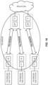
- Solution #8 provides an option for 5G system appearing as a TSN bridge (black box) for integration with TSN, as described in section 6.8. However, solution #8 only illustrated the scenarios of single UE, via a UPF connected to TSN. Further study is required to clarify the management of 5G virtual bridges when multiple UEs and multiple UPFs are serving for TSN. Following 3 options are analysed for different granularity of 5G virtual bridge:
- Option 1 Single virtual bridge including all UEs and UPFs.
- All UEs and UPFs serving for the specific TSN are grouped into a single virtual bridge.
- the bridge ID can be assigned by mobile operator or TSN operator.
- the capabilities of each port in UEs and UPFs are integrated as parts of the configuration of the 5G virtual bridge, which is notified to TSN AF and delivered to CNC for TSN bridge registration and modification. Any event of PDU session establishment/modification may cause the reconfiguration of the 5G virtual bridge.
- the configuration data of the bridge and the frequency of reconfiguration may increase sharply, when the scale of the connected UEs increased.
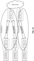
- Option 2 Per UPF based 5G virtual bridge.
- TSN AF ay bind the bridge ID with the UPF ID.
- the capabilities of each port in UEs and UPF are integrated as parts of the configuration of the 5G virtual bridge, which is notified to TSN AF and delivered to CNC for TSN bridge registration and modification.
- this option can lower the scale of a 5G virtual bridge configuration and simplify the connection between TSN and UPF.
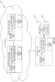
- Option 3 Per UE based 5G virtual bridge.
- TSN AF may bind the bridge ID with the UE ID (such as GPSI).
- the end points of each PDU sessions (in UE and UPF) is binding as virtual ports of the TSN bridge. Based on this option, the configuration of each 5G virtual bridge is much simple and flexible. It can avoid bridge reconfiguration caused by other UEs.
- one TSN bridge port can be configured with one configuration table for each traffic class, includes bandwidth availability, bridge delay, and traffic scheduling etc.
- the maximum number of traffic classes in a TSN port is 8.
- the bridge port exposed to CNC should be configured to support the same traffic classes.
- One or more traffic classes are mapped into a 5G QoS flow for transmission.
- the mapping between TSN traffic class and QoS flow is pre-configured or based on policy control.
- the TSN AF binds the TSN ports on the UE and UPF side with their MAC addresses.
- TSN AF can bind the TSN ports with PDU sessions.
- the TSN ports in UE side can be mapped with PDU session ID.
- the bridge port in UPF side cane be mapped with the combination of UPF ID, and PDU session ID.
- a single TSN network may carry variety of time-sensitive data streams, but the allocation of bandwidth should be centrally managed in CNC.
- CNC can reserve the resource for a stream based on the differentiation of traffic classes.
- up to 8 QoS flows for TSN traffic may be established in each PDU session, which is binding with different TSN traffic classes.
- the total number and parameters of the QoS flows can be configured in UE subscription, MNO's policy, AF request or pre-configuration.
- Figure 6 .x.1.2-1 shows an example of PDU session based TSN ports configuration.
- FIG. 23 is a schematic block diagram of a network node 2300 according to some embodiments of the present disclosure.
- the network node 2300 may be, for example, a base station 102 or 106 or a network node that implements a NF(s).
- network node 2300 includes a control system 2302 that includes one or more processors 2304 (e.g., Central Processing Units (CPUs), Application Specific Integrated Circuits (ASICs), Field Programmable Gate Arrays (FPGAs), and/or the like), memory 2306, and a network interface 2308.
- the one or more processors 2304 are also referred to herein as processing circuitry.
- the network node 2300 includes one or more radio units 2310 that each includes one or more transmitters 2312 and one or more receivers 2314 coupled to one or more antennas 2316.
- the radio units 2310 may be referred to or be part of radio interface circuitry.
- the radio unit(s) 2310 is external to the control system 2302 and connected to the control system 2302 via, e.g., a wired connection (e.g., an optical cable).
- the radio unit(s) 2310 and potentially the antenna(s) 2316 are integrated together with the control system 2302.
- the one or more processors 2304 operate to provide one or more functions of a network node 2300 as described herein.
- the function(s) are implemented in software that is stored, e.g., in the memory 2306 and executed by the one or more processors 2304.
- Figure 24 is a schematic block diagram that illustrates a virtualized embodiment of the network node 2300 according to some embodiments of the present disclosure. This discussion is equally applicable to other types of network nodes. Further, other types of network nodes may have similar virtualized architectures.
- a "virtualized" network node is an implementation of the network node 2300 in which at least a portion of the functionality of the network node 2300 is implemented as a virtual component(s) (e.g., via a virtual machine(s) executing on a physical processing node(s) in a network(s)).
- the network node 2300 includes one or more processing nodes 2400 coupled to or included as part of a network(s) 2402.
- Each processing node 2400 includes one or more processors 2404 (e.g., CPUs, ASICs, FPGAs, and/or the like), memory 2406, and a network interface 2408.
- the network node 2300 may include the control system 2302 that includes the one or more processors 2304 (e.g., CPUs, ASICs, FPGAs, and/or the like), the memory 2306, and the network interface 2308 and the one or more radio units 2310 that each includes the one or more transmitters 2312 and the one or more receivers 2314 coupled to the one or more antennas 2316, as described above.
- the control system 2302 is connected to the radio unit(s) 2310 via, for example, an optical cable or the like. If present, the control system 2302 is connected to the one or more processing nodes 2400 coupled to or included as part of the network(s) 2402 via the network interface 2308.
- functions 2410 of the network node 2300 described herein are implemented at the one or more processing nodes 2400 or distributed across the control system 2302 and the one or more processing nodes 2400 in any desired manner.
- some or all of the functions 2410 of the network node 2300 described herein are implemented as virtual components executed by one or more virtual machines implemented in a virtual environment(s) hosted by the processing node(s) 2400.
- additional signaling or communication between the processing node(s) 2400 and the control system 2302 is used in order to carry out at least some of the desired functions 2410.
- the control system 2302 may not be included, in which case the radio unit(s) 2310 communicate directly with the processing node(s) 2400 via an appropriate network interface(s).
- a computer program including instructions which, when executed by at least one processor, causes the at least one processor to carry out the functionality of the network node 2300 or a node (e.g., a processing node 2400) implementing one or more of the functions 2410 of the network node 2300 in a virtual environment according to any of the embodiments described herein is provided.
- a carrier comprising the aforementioned computer program product is provided. The carrier is one of an electronic signal, an optical signal, a radio signal, or a computer readable storage medium (e.g., a non-transitory computer readable medium such as memory).
- FIG 25 is a schematic block diagram of the network node 2300 according to some other embodiments of the present disclosure.
- the network node 2300 includes one or more modules 2500, each of which is implemented in software.
- the module(s) 2500 provide the functionality of the network node 2300 described herein. This discussion is equally applicable to the processing node 2400 of Figure 24 where the modules 2500 may be implemented at one of the processing nodes 2400 or distributed across multiple processing nodes 2400 and/or distributed across the processing node(s) 2400 and the control system 2302.
- FIG. 26 is a schematic block diagram of a UE 2600 according to some embodiments of the present disclosure.
- the UE 2600 includes one or more processors 2602 (e.g., CPUs, ASICs, FPGAs, and/or the like), memory 2604, and one or more transceivers 2606 each including one or more transmitters 2608 and one or more receivers 2610 coupled to one or more antennas 2612.
- the transceiver(s) 2606 includes radio-front end circuitry connected to the antenna(s) 2612 that is configured to condition signals communicated between the antenna(s) 2612 and the processor(s) 2602, as will be appreciated by on of ordinary skill in the art.
- the processors 2602 are also referred to herein as processing circuitry.
- the transceivers 2606 are also referred to herein as radio circuitry.
- the functionality of the UE 2600 described above may be fully or partially implemented in software that is, e.g., stored in the memory 2604 and executed by the processor(s) 2602.
- the UE 2600 may include additional components not illustrated in Figure 26 such as, e.g., one or more user interface components (e.g., an input/output interface including a display, buttons, a touch screen, a microphone, a speaker(s), and/or the like and/or any other components for allowing input of information into the UE 2600 and/or allowing output of information from the UE 2600), a power supply (e.g., a battery and associated power circuitry), etc.
- a power supply e.g., a battery and associated power circuitry
- a computer program including instructions which, when executed by at least one processor, causes the at least one processor to carry out the functionality of the UE 2600 according to any of the embodiments described herein is provided.
- a carrier comprising the aforementioned computer program product is provided.
- the carrier is one of an electronic signal, an optical signal, a radio signal, or a computer readable storage medium (e.g., a non-transitory computer readable medium such as memory).
- FIG. 27 is a schematic block diagram of the UE 2600 according to some other embodiments of the present disclosure.
- the UE 2600 includes one or more modules 2700, each of which is implemented in software.
- the module(s) 2700 provide the functionality of the UE 2600 described herein.
- any appropriate steps, methods, features, functions, or benefits disclosed herein may be performed through one or more functional units or modules of one or more virtual apparatuses.
- Each virtual apparatus may comprise a number of these functional units.
- These functional units may be implemented via processing circuitry, which may include one or more microprocessor or microcontrollers, as well as other digital hardware, which may include Digital Signal Processor (DSPs), special-purpose digital logic, and the like.
- the processing circuitry may be configured to execute program code stored in memory, which may include one or several types of memory such as Read Only Memory (ROM), Random Access Memory (RAM), cache memory, flash memory devices, optical storage devices, etc.
- Program code stored in memory includes program instructions for executing one or more telecommunications and/or data communications protocols as well as instructions for carrying out one or more of the techniques described herein.
- the processing circuitry may be used to cause the respective functional unit to perform corresponding functions according one or more embodiments of the present disclosure.
Landscapes
- Engineering & Computer Science (AREA)
- Computer Networks & Wireless Communication (AREA)
- Signal Processing (AREA)
- Computer Security & Cryptography (AREA)
- Mobile Radio Communication Systems (AREA)
Claims (16)
- Procédé réalisé par un ou plusieurs noeuds de réseau d'un système de communication cellulaire, le système de communication cellulaire fonctionnant en tant qu'un pont de réseautage sensible au temps, TSN, virtuel d'un réseau TSN,dans lequel les paramètres de configuration de pont TSN suivants sont fournis par une station de configuration de réseau centralisée, CNC, couplée en communication à un réseau central (110) du système de communication cellulaire, aux un ou plusieurs noeuds de réseau du réseau central (110), pour configurer le mécanisme de régulation de sortie mis en oeuvre par chaque port de sortie :• un paramètre AdminControlList qui décrit une séquence d'états de fonctionnement de grille dans une liste de GateControlEntries, dans lequel chaque GateControlEntry dans la liste de GateControlEntries se compose de :o un paramètre GateStatesValue qui est une liste dans laquelle, pour chaque classe de trafic, TC, prise en charge par un port courant, une entité de la liste indique une valeur, « ouvert » ou « fermé », pour l'état d'une grille correspondant à des files d'attente du port ; eto un paramètre TimeIntervalValue qui spécifie le temps pendant lequel les états courants des grilles doivent être appliqués ; si le temps spécifié par TimeIntervalValue a expiré, l'opération de grille suivante est exécutée, dans lequel la somme de TimeIntervalValues détermine le temps de cycle de grille et dans lequel, après un cycle, la première opération dans la liste de commandes de grille est exécutée à nouveau ; et• un paramètre AdminBaseTime qui spécifie quand l'exécution d'un cycle de grille doit commencer,le procédé étant caractérisé en ce qu'il comprend :
la fourniture (Fig. 6, étape 4), à la CNC, d'un ou plusieurs paramètres relatifs à des capacités du pont TSN virtuel, dans lequel les un ou plusieurs paramètres relatifs aux capacités du pont TSN virtuel comprennent :un premier paramètre qui définit la valeur minimale de la TimeIntervalValue pour la commande de grille du mécanisme de régulation de sortie mis en oeuvre par chacun des ports de sortie ; etun deuxième paramètre qui informe la CNC que le pont TSN virtuel ou un port de sortie particulier du pont TSN virtuel est restreint à une grille exclusive, dans lequel une grille exclusive signifie qu'uniquement des trames appartenant à une classe de trafic TSN unique peuvent être transmises depuis des ports de sortie du pont TSN virtuel ou depuis le port de sortie particulier du pont TSN virtuel à un moment donné. - Procédé selon la revendication 1,dans lequel, lors d'un fonctionnement en tant qu'un pont TSN virtuel, le système de communication cellulaire doit réaliser la planification sur ses ports de sortie correspondants, dans lequel la planification signifie que la transmission de trames depuis chaque file d'attente, qui est associée à la TC, est planifiée par rapport à une échelle de temps connue, dans lequel une grille de transmission est associée à chaque file d'attente, où l'état de la grille de transmission détermine si une trame mise en file d'attente peut ou non être sélectionnée pour une transmission, dans lequel la grille de transmission comporte deux états : ouvert et fermé, dans lequel une liste de commandes de grille est associée à chaque port de sortie et contient une liste ordonnée d'opérations de grille, dans lequel chaque opération de grille change l'état de grille de transmission pour la grille de transmission associée à chacune des files d'attente de TC du port en fonction d'un temps planifié, dans lequel la période de temps au cours de laquelle la séquence d'opérations de grille dans la liste de commandes de grille se répète est appelée un cycle de grille, etdans lequel la CNC configure les réservations de ressources de réseau et calcule l'itinéraire et la planification de temps nécessaire pour la transmission de bout en bout de chaque flux TSN, et configure les ponts TSN avec la planification de temps calculée.
- Procédé selon la revendication 1 ou 2, dans lequel :les un ou plusieurs noeuds de réseau se composent d'une fonction d'application associée au réseau central (110), dans lequella fourniture (Fig. 6, étape 4) des ou plusieurs paramètres relatifs à des capacités du pont TSN virtuel au dispositif de commande associé au réseau TSN comprend la fourniture (Fig. 6, étape 4), depuis la fonction d'application à la CNC, des un ou plusieurs paramètres relatifs à des capacités du pont TSN virtuel.
- Procédé selon la revendication 3, comprenant en outre la réception (Fig. 6, étape 3), au niveau de la fonction d'application, d'au moins le premier paramètre depuis un port de sortie via une procédure de réseau cellulaire.
- Procédé selon la revendication 3 ou 4, comprenant en outre :la réception (Fig. 7, étape 1), depuis la CNC, d'une pluralité de paramètres de configuration de pont TSN ; etsoit (a) l'envoi (Fig. 7, étape 2) uniquement d'un sous-ensemble de la pluralité de paramètres de configuration de pont TSN à un ou plusieurs ports de sortie soit (b) l'envoi (Fig. 7, étape 2), aux un ou plusieurs autres noeuds de réseau, d'informations correspondant à une traduction du sous-ensemble de la pluralité de paramètres de configuration de pont TSN en un ou plusieurs paramètres du système de communication cellulaire ;dans lequel le sous-ensemble de la pluralité de paramètres de configuration de pont TSN est plus petit que l'intégralité de la pluralité de paramètres de configuration de pont TSN.
- Procédé selon la revendication 5, dans lequel le réseau TSN est un réseau TSN IEEE 802.1Qbv, et le sous-ensemble de la pluralité de paramètres de configuration de pont TSN comprend en outre :i. queueMaxSDUTable,ii. SupportedListMax,iii. AdminGateStates, ouiv. toute combinaison de deux ou plus parmi i, ii et iii.
- Procédé selon la revendication 1, dans lequel :un équipement utilisateur, UE, associé à un traducteur TSN qui réalise une commande de grille, est un port de sortie ; etle procédé comprend la fourniture, depuis l'UE aux un ou plusieurs noeuds de réseau, du premier paramètre via une procédure de réseau cellulaire.
- Procédé selon la revendication 7, dans lequel la procédure de réseau cellulaire est une procédure d'établissement de session d'unité de données de protocole, PDU, ou une procédure de modification de session PDU.
- Procédé selon la revendication 1, dans lequel :une fonction de plan utilisateur, UPF, du réseau central (110), l'UPF étant associée à un traducteur TSN qui réalise une commande de grille, est un port de sortie ; etle procédé comprend la fourniture, depuis l'UPF aux un ou plusieurs noeuds de réseau, du premier paramètre via une procédure de réseau cellulaire.
- Procédé selon la revendication 9, dans lequel la procédure de réseau cellulaire est une procédure d'établissement de session N4 ou une procédure de modification de session N4.
- Procédé selon l'une quelconque des revendications 1 à 10, dans lequel le pont TSN virtuel est un pont TSN virtuel dans un réseau TSN IEEE 802.1Qbv.
- Procédé selon la revendication 11, dans lequel le système de communication cellulaire est un système de cinquième génération, 5GS, de projet de partenariat de troisième génération, 3GPP.
- Support lisible par ordinateur comprenant des portions de code qui, lorsqu'elles sont exécutées sur un processeur, configurent le processeur pour réaliser le procédé selon l'une quelconque des revendications 1 à 12.
- Noeud de réseau (210 ; 212) pour un système de communication cellulaire (100), le système de communication cellulaire (100) fonctionnant en tant qu'un pont de réseautage sensible au temps, TSN, virtuel (400) d'un réseau TSN,dans lequel les paramètres de configuration de pont TSN suivants sont fournis par une station de configuration de réseau centralisée, CNC, couplée en communication à un réseau central (110) du système de communication cellulaire, aux un ou plusieurs noeuds de réseau du réseau central (110), pour configurer le mécanisme de régulation de sortie mis en oeuvre par chaque port de sortie :• un paramètre AdminControlList qui décrit une séquence d'états de fonctionnement de grille dans une liste de GateControlEntries, dans lequel chaque GateControlEntry dans la liste de GateControlEntries se compose de :o un paramètre GateStatesValue qui est une liste dans laquelle, pour chaque classe de trafic, TC, prise en charge par un port courant, une entité de la liste indique une valeur, « ouvert » ou « fermé », pour l'état d'une grille correspondant à des files d'attente du port ; eto un paramètre TimeIntervalValue qui spécifie le temps pendant lequel les états courants des grilles doivent être appliqués ; si le temps spécifié par TimeIntervalValue a expiré, l'opération de grille suivante est exécutée, dans lequel la somme de TimeIntervalValues détermine le temps de cycle de grille et dans lequel, après un cycle, la première opération dans la liste de commandes de grille est exécutée à nouveau ; et• un paramètre AdminBaseTime qui spécifie quand l'exécution d'un cycle de grille doit commencer,dans lequel le noeud de réseau (210 ; 212) est caractérisé en ce qu'il est apte à :
fournir (Fig. 6, étape 4), à la CNC, un ou plusieurs paramètres relatifs à des capacités du pont TSN virtuel (400), dans lequel les un ou plusieurs paramètres relatifs aux capacités du pont TSN virtuel (400) comprennent :un premier paramètre qui définit la valeur minimale de la TimeIntervalValue pour la commande de grille du mécanisme de régulation de sortie mis en oeuvre par chacun des ports de sortie ; etun deuxième paramètre qui informe la CNC que le pont TSN virtuel (400) ou un port de sortie particulier du pont TSN virtuel (400) est restreint à une grille exclusive, dans lequel une grille exclusive signifie qu'uniquement des trames appartenant à une classe de trafic TSN unique peuvent être transmises depuis un ou plusieurs ports de sortie du pont TSN virtuel (400) ou depuis le port de sortie particulier du pont TSN virtuel (400) à un moment donné. - Noeud de réseau selon la revendication 14,dans lequel, lors d'un fonctionnement en tant qu'un pont TSN virtuel, le système de communication cellulaire doit réaliser la planification sur ses ports de sortie correspondants, dans lequel la planification signifie que la transmission de trames depuis chaque file d'attente, qui est associée à la TC, est planifiée par rapport à une échelle de temps connue, dans lequel une grille de transmission est associée à chaque file d'attente, où l'état de la grille de transmission détermine si une trame mise en file d'attente peut ou non être sélectionnée pour une transmission, dans lequel la grille de transmission comporte deux états : ouvert et fermé, dans lequel une liste de commandes de grille est associée à chaque port de sortie et contient une liste ordonnée d'opérations de grille, dans lequel chaque opération de grille change l'état de grille de transmission pour la grille de transmission associée à chacune des files d'attente de TC du port en fonction d'un temps planifié, dans lequel la période de temps au cours de laquelle la séquence d'opérations de grille dans la liste de commandes de grille se répète est appelée un cycle de grille, etdans lequel la CNC configure les réservations de ressources de réseau et calcule l'itinéraire et la planification de temps nécessaire pour la transmission de bout en bout de chaque flux TSN, et configure les ponts TSN avec la planification de temps calculée.
- Noeud de réseau (210 ; 212) selon la revendication 15, dans lequel le noeud de réseau (210 ; 212) est en outre apte à réaliser le procédé selon l'une quelconque des revendications 3 à 12.
Applications Claiming Priority (2)
| Application Number | Priority Date | Filing Date | Title |
|---|---|---|---|
| US201962805727P | 2019-02-14 | 2019-02-14 | |
| PCT/IB2020/051264 WO2020165857A1 (fr) | 2019-02-14 | 2020-02-14 | Prise en charge de système 5g pour la gestion de pont de tsn virtuel, le mappage de qos et la planification de qbv de tsn |
Publications (2)
| Publication Number | Publication Date |
|---|---|
| EP3925096A1 EP3925096A1 (fr) | 2021-12-22 |
| EP3925096B1 true EP3925096B1 (fr) | 2023-05-10 |
Family
ID=69740436
Family Applications (1)
| Application Number | Title | Priority Date | Filing Date |
|---|---|---|---|
| EP20708642.2A Active EP3925096B1 (fr) | 2019-02-14 | 2020-02-14 | Prise en charge de système 5g pour la gestion de pont de tsn virtuel, le mappage de qos et la planification de qbv de tsn |
Country Status (5)
| Country | Link |
|---|---|
| US (3) | US20220046462A1 (fr) |
| EP (1) | EP3925096B1 (fr) |
| CN (1) | CN113424463B (fr) |
| BR (1) | BR112021013378A2 (fr) |
| WO (1) | WO2020165857A1 (fr) |
Families Citing this family (45)
| Publication number | Priority date | Publication date | Assignee | Title |
|---|---|---|---|---|
| CN110351201B (zh) * | 2018-04-04 | 2021-09-14 | 华为技术有限公司 | 一种数据处理方法及装置 |
| CN111200878B (zh) * | 2018-11-19 | 2022-04-22 | 华为技术有限公司 | 信息传输方法及其装置 |
| US12166683B2 (en) | 2018-11-19 | 2024-12-10 | Telefonaktiebolaget Lm Ericsson (Publ) | Output pacing in a cellular communications system serving as a time-sensitive networking (TSN) node |
| US12041481B2 (en) | 2019-01-15 | 2024-07-16 | Telefonaktiebolaget Lm Ericsson (Publ) | TSN-cellular communication system QoS mapping and RAN optimization based on TSN traffic pattern related information |
| BR112021013378A2 (pt) | 2019-02-14 | 2021-09-14 | Telefonaktiebolaget Lm Ericsson (Publ) | Métodos realizados por um ou mais nós de rede de um sistema de comunicações de celular, por uma função de aplicativo associada a uma rede de rede sensível ao tempo e por uma função de controle de política em uma rede principal de um sistema de comunicações de celular, nós de rede para um sistema de comunicações de celular, que implanta uma função de aplicativo associada a uma rede de rede sensível ao tempo e que implanta uma função de controle de política para uma rede principal de um sistema de comunicações de celular, e, sistema de comunicações de celular para operação como duas ou mais pontes de rede sensível ao tempo virtual |
| US11178592B2 (en) * | 2019-02-15 | 2021-11-16 | Ofinno, Llc | Device configuration for time sensitive network bridge |
| WO2020221468A1 (fr) * | 2019-05-02 | 2020-11-05 | Nokia Solutions And Networks Gmbh & Co.Kg. | Intégration de réseau de communication dans un système de mise en réseau sensible au temps |
| CN113796117B (zh) * | 2019-05-07 | 2024-11-26 | 中兴通讯股份有限公司 | 用于无线通信中的时间映射的方法、装置和系统 |
| JP7344990B2 (ja) | 2019-06-03 | 2023-09-14 | テレフオンアクチーボラゲット エルエム エリクソン(パブル) | TSNおよび5GS QoSマッピング-ユーザプレーンベースの方法 |
| CN111818671B (zh) * | 2019-07-05 | 2022-02-01 | 维沃移动通信有限公司 | 支持端口控制的方法及设备 |
| CN111818666B (zh) * | 2019-07-12 | 2023-02-03 | 维沃移动通信有限公司 | 支持端口关联的方法、网关选择的方法及通信设备 |
| CN113556763B (zh) * | 2019-09-27 | 2023-05-16 | 腾讯科技(深圳)有限公司 | 实现时间敏感网络的数据传输的方法、相关设备及介质 |
| EP4055786A1 (fr) * | 2019-11-08 | 2022-09-14 | Telefonaktiebolaget LM Ericsson (publ) | Mappage de qos |
| WO2021093158A1 (fr) * | 2020-01-13 | 2021-05-20 | Zte Corporation | Procédé de configuration adaptative de transmission de flux de données |
| US11757788B2 (en) * | 2020-03-09 | 2023-09-12 | Nippon Telegraph And Telephone Corporation | Signal transfer system, signal transfer device, signal transfer method and signal transfer program |
| WO2021181479A1 (fr) * | 2020-03-09 | 2021-09-16 | 日本電信電話株式会社 | Système de transfert de signal, dispositif de transfert de signal, procédé de transfert de signal et programme de transfert de signal |
| EP3879764B1 (fr) * | 2020-03-11 | 2023-08-23 | ABB Schweiz AG | Transport d'un message provenant d'un terminal industriel sur un réseau ethernet |
| EP3962004A1 (fr) * | 2020-08-27 | 2022-03-02 | ABB Schweiz AG | Système et procédé pour activer une configuration de flux tsn |
| US11564123B2 (en) * | 2020-09-30 | 2023-01-24 | Kabushiki Kaisha Toshiba | Virtual time-sensitive networking bridge over a 5G wireless system |
| EP4256844A1 (fr) * | 2020-12-03 | 2023-10-11 | InterDigital Patent Holdings, Inc. | Mécanisme pour le fonctionnement d'un pont virtuel tsn 3gpp dans un réseau centralisé / modèle d'utilisateur distribué dans un système 5g |
| US11374872B1 (en) * | 2020-12-08 | 2022-06-28 | Pensando Systems, Inc. | Methods and systems for adaptive network quality of service for latency critical applications |
| CN112511462B (zh) * | 2020-12-17 | 2022-07-26 | 上海交通大学 | 一种软件定义工业异构时间敏感网络系统及资源调度方法 |
| KR102661404B1 (ko) * | 2021-01-27 | 2024-04-26 | 한국전자통신연구원 | 패킷전화 단말 장치 및 그 동작 방법 |
| US11824788B2 (en) * | 2021-04-22 | 2023-11-21 | Moxa Inc. | Apparatuses and methods for supporting class-based scheduling in a time-sensitive networking (TSN) network |
| CN115484161B (zh) * | 2021-05-28 | 2024-07-19 | 南宁富联富桂精密工业有限公司 | Tsn网络配置方法、装置及计算机可读存储介质 |
| CN115460651B (zh) * | 2021-06-08 | 2025-12-09 | 展讯通信(上海)有限公司 | 数据传输方法及装置、可读存储介质、终端 |
| EP4120658A1 (fr) * | 2021-07-15 | 2023-01-18 | Sandvine Corporation | Système et procédé de gestion de trafic de réseau utilisant les principes de proportion équitable |
| WO2023009043A1 (fr) * | 2021-07-27 | 2023-02-02 | Telefonaktiebolaget Lm Ericsson (Publ) | Nœud de réseau et procédé dans ce dernier pour une utilisation optimisée de ports de pont de système 5g |
| CN115884215A (zh) * | 2021-09-29 | 2023-03-31 | 大唐移动通信设备有限公司 | 一种QoS参数配置方法、装置及设备 |
| US12127149B2 (en) * | 2021-10-19 | 2024-10-22 | At&T Intellectual Property I, L.P. | API driven subscriber IMS registration status changes and IMS routing steering |
| KR102606909B1 (ko) | 2021-10-21 | 2023-11-24 | 한국철도기술연구원 | 데이터 전송 장치 및 방법 |
| US11818646B2 (en) * | 2021-11-15 | 2023-11-14 | Kabushiki Kaisha Toshiba | System-level schedule generation for integrated TSN and 5G deployments |
| CN116193626A (zh) * | 2021-11-26 | 2023-05-30 | 中兴通讯股份有限公司 | 数据传输控制方法、设备及存储介质 |
| WO2023141796A1 (fr) * | 2022-01-26 | 2023-08-03 | Qualcomm Incorporated | Techniques de prise en charge de trames ethernet non étiquetées |
| CN114374993B (zh) * | 2022-02-24 | 2024-01-12 | 北京东土科技股份有限公司 | 一种5g-tsn终端网关 |
| WO2023184059A1 (fr) * | 2022-03-28 | 2023-10-05 | Zte Corporation | Communication déterministe avec mise en réseau sensible au temps dans un réseau de transport |
| CN117319135A (zh) * | 2022-06-24 | 2023-12-29 | 中兴通讯股份有限公司 | Tsn网络的桥接方法、装置、电子设备及存储介质 |
| EP4568407A4 (fr) * | 2022-08-05 | 2025-11-26 | Sony Group Corp | Dispositif de traitement d'informations et procédé de traitement d'informations |
| WO2024037745A1 (fr) * | 2022-08-15 | 2024-02-22 | Volkswagen Aktiengesellschaft | Pont 5g-tsn, pont, appareil, procédé, et programme informatique d'attribution de flux de qualité de service |
| CN117834341A (zh) * | 2022-09-27 | 2024-04-05 | 中兴通讯股份有限公司 | 数据传输方法、装置、存储介质及电子装置 |
| WO2024102035A1 (fr) * | 2022-11-07 | 2024-05-16 | Telefonaktiebolaget Lm Ericsson (Publ) | Rapport d'informations de caractéristiques sans fil pour une communication sensible au temps |
| CN115811799B (zh) * | 2023-01-20 | 2023-04-21 | 北京科技大学 | 一种基于ddpg的5g-tsn联合资源调度装置及方法 |
| US12432715B2 (en) | 2023-02-10 | 2025-09-30 | Cisco Technology, Inc. | Automatic determination of components for time sensitive networking |
| WO2025024854A1 (fr) * | 2023-07-27 | 2025-01-30 | Dolby Network Technologies Llc | Ia-ml utilisée pour distribuer ia-ml sur un réseau 5g-tsn |
| US12470480B2 (en) * | 2024-04-29 | 2025-11-11 | Mellanox Technologies, Ltd. | Hardware-accelerated flexible steering rules over service function chaining (SFC) |
Family Cites Families (25)
| Publication number | Priority date | Publication date | Assignee | Title |
|---|---|---|---|---|
| EP2583413A1 (fr) * | 2010-06-21 | 2013-04-24 | Deutsche Telekom AG | Procédé et système d'utilisation efficiente d'un réseau de télécommunications et de la connexion entre le réseau de télécommunications et un équipement dans les locaux du client |
| WO2014126512A1 (fr) * | 2013-02-13 | 2014-08-21 | Telefonaktiebolaget L M Ericsson (Publ) | Station de base radio et procédé réalisé sur celle-ci pour envoyer une configuration d'alignement temporel à un équipement d'utilisateur |
| US10447583B2 (en) * | 2015-11-09 | 2019-10-15 | Telefonaktiebolaget Lm Ericsson (Publ) | Packet processing technique for a communication network |
| US10805222B2 (en) * | 2017-05-01 | 2020-10-13 | General Electric Company | Resilient network configuration for time sensitive traffic |
| US20180184428A1 (en) | 2016-12-28 | 2018-06-28 | Laurent Cariou | Associating and securitizing distributed multi-band link aggregation devices |
| US10292087B2 (en) * | 2017-02-01 | 2019-05-14 | Futurewei Technologies, Inc. | System and method for access barring |
| CN110431769B (zh) * | 2017-03-13 | 2021-06-04 | 西门子股份公司 | 用于在tsn中的时间控制的数据传输的方法和设备 |
| WO2019007516A1 (fr) | 2017-07-06 | 2019-01-10 | Siemens Aktiengesellschaft | Procédé de transmission performante de données dans un réseau de données, à conditions en partie en temps réel, et dispositif de mise en oeuvre dudit procédé |
| WO2019145028A1 (fr) * | 2018-01-24 | 2019-08-01 | Renesas Electronics Corporation | Réseautage sensible au temps |
| EP3759878B1 (fr) * | 2018-02-28 | 2025-09-17 | Nokia Technologies Oy | Intégration transparente de réseau 3gpp dans un réseau industriel à base de tsn |
| CN108366023B (zh) * | 2018-03-20 | 2020-08-11 | 西安电子科技大学 | 用于时延敏感网络的防碰撞流预留带宽系统及其方法 |
| JP6889126B2 (ja) * | 2018-03-20 | 2021-06-18 | 株式会社東芝 | 転送制御装置、転送制御方法及びプログラム |
| US10880895B2 (en) * | 2018-05-27 | 2020-12-29 | Brian Gordaychik | Variable length downlink control information formats for next generation radio technologies |
| US11191052B2 (en) * | 2018-08-13 | 2021-11-30 | Samsung Electronics Co., Ltd. | Wireless communication network in wireless communication system |
| CN112740624B (zh) | 2018-08-13 | 2024-04-23 | 诺基亚技术有限公司 | 支持TSN-3GPP网络集成中的E2E QoS要求的实现 |
| CN112567714B (zh) | 2018-08-14 | 2022-07-26 | 华为技术有限公司 | 基于时间感知服务质量的通信方法及设备 |
| WO2020035133A1 (fr) * | 2018-08-14 | 2020-02-20 | Nokia Solutions And Networks Oy | Adaptation et mise en forme de qualité de service (qos) de projet de partenariat de troisième génération (3gpp)-réseautage sensible au temps (tsn) (3gpp-tsn) mutuelle |
| US11297541B2 (en) * | 2018-08-17 | 2022-04-05 | Qualcomm Incorporated | Signaling timing information for a time sensitive network in a wireless communications system |
| US11202222B2 (en) * | 2018-10-24 | 2021-12-14 | Qualcomm Incorporated | Quality of service mapping for time-sensitive network traffic in a wireless communication system |
| US12166683B2 (en) | 2018-11-19 | 2024-12-10 | Telefonaktiebolaget Lm Ericsson (Publ) | Output pacing in a cellular communications system serving as a time-sensitive networking (TSN) node |
| US11930392B2 (en) | 2018-11-20 | 2024-03-12 | Nokia Technologies Oy | Latency-bounded packet delivery in mobile communication system |
| US12041481B2 (en) | 2019-01-15 | 2024-07-16 | Telefonaktiebolaget Lm Ericsson (Publ) | TSN-cellular communication system QoS mapping and RAN optimization based on TSN traffic pattern related information |
| BR112021013378A2 (pt) | 2019-02-14 | 2021-09-14 | Telefonaktiebolaget Lm Ericsson (Publ) | Métodos realizados por um ou mais nós de rede de um sistema de comunicações de celular, por uma função de aplicativo associada a uma rede de rede sensível ao tempo e por uma função de controle de política em uma rede principal de um sistema de comunicações de celular, nós de rede para um sistema de comunicações de celular, que implanta uma função de aplicativo associada a uma rede de rede sensível ao tempo e que implanta uma função de controle de política para uma rede principal de um sistema de comunicações de celular, e, sistema de comunicações de celular para operação como duas ou mais pontes de rede sensível ao tempo virtual |
| CN111865830B (zh) * | 2019-04-29 | 2022-04-22 | 华为技术有限公司 | 一种时延敏感网络业务tsn的处理方法、装置及系统 |
| WO2020239231A1 (fr) | 2019-05-30 | 2020-12-03 | Nokia Solutions And Networks Gmbh & Co. Kg | Activation de flux de session pdu et de qos dans des ponts ethernet basés sur 3gpp |
-
2020
- 2020-02-14 BR BR112021013378-0A patent/BR112021013378A2/pt not_active IP Right Cessation
- 2020-02-14 EP EP20708642.2A patent/EP3925096B1/fr active Active
- 2020-02-14 WO PCT/IB2020/051264 patent/WO2020165857A1/fr not_active Ceased
- 2020-02-14 CN CN202080014340.3A patent/CN113424463B/zh active Active
- 2020-02-14 US US17/431,202 patent/US20220046462A1/en not_active Abandoned
-
2022
- 2022-07-13 US US17/863,645 patent/US11825337B2/en active Active
-
2023
- 2023-02-07 US US18/106,761 patent/US11950127B2/en active Active
Also Published As
| Publication number | Publication date |
|---|---|
| BR112021013378A2 (pt) | 2021-09-14 |
| US11950127B2 (en) | 2024-04-02 |
| CN113424463A (zh) | 2021-09-21 |
| US11825337B2 (en) | 2023-11-21 |
| US20220046462A1 (en) | 2022-02-10 |
| US20230180053A1 (en) | 2023-06-08 |
| US20220369157A1 (en) | 2022-11-17 |
| WO2020165857A1 (fr) | 2020-08-20 |
| EP3925096A1 (fr) | 2021-12-22 |
| CN113424463B (zh) | 2022-12-06 |
Similar Documents
| Publication | Publication Date | Title |
|---|---|---|
| EP3925096B1 (fr) | Prise en charge de système 5g pour la gestion de pont de tsn virtuel, le mappage de qos et la planification de qbv de tsn | |
| US12041481B2 (en) | TSN-cellular communication system QoS mapping and RAN optimization based on TSN traffic pattern related information | |
| US12166683B2 (en) | Output pacing in a cellular communications system serving as a time-sensitive networking (TSN) node | |
| US12167275B2 (en) | TSN and 5GS QoS mapping—a user plane based method | |
| US11956157B2 (en) | Activation of PDU session and QOS flows in 3GPP-based ethernet bridges | |
| US12432119B2 (en) | Integration of communication network in time sensitive networking system | |
| EP4088434A1 (fr) | Mappage de qos de tsc-5g en tenant compte d'informations de trafic d'assistance et de règles pcc pour un mappage de trafic tsc et une liaison de flux de qos 5g | |
| WO2019157855A1 (fr) | Procédé de traitement de paramètre de qualité de service (qos), élément de réseau, système et support de stockage | |
| EP4561148A1 (fr) | Procédé et appareil de communication | |
| EP4144059A1 (fr) | Mécanisme de commande de réservation de flux dans un réseau de communication pour système de réseautage sensible au temps | |
| CN111698787B (zh) | 调度规则确定方法及其装置 | |
| US11375024B1 (en) | Programmable networking device for user plane function | |
| WO2022242201A1 (fr) | Procédé de communication sans fil, appareil de communication et système de communication | |
| WO2023042044A1 (fr) | Signalisation de commande entre des entités de réseau 3gpp et un réseau de transport | |
| CN121217675A (zh) | 通信方法及装置 | |
| WO2023005728A1 (fr) | Procédé de communication, appareil et système |
Legal Events
| Date | Code | Title | Description |
|---|---|---|---|
| STAA | Information on the status of an ep patent application or granted ep patent |
Free format text: STATUS: UNKNOWN |
|
| STAA | Information on the status of an ep patent application or granted ep patent |
Free format text: STATUS: THE INTERNATIONAL PUBLICATION HAS BEEN MADE |
|
| PUAI | Public reference made under article 153(3) epc to a published international application that has entered the european phase |
Free format text: ORIGINAL CODE: 0009012 |
|
| STAA | Information on the status of an ep patent application or granted ep patent |
Free format text: STATUS: REQUEST FOR EXAMINATION WAS MADE |
|
| 17P | Request for examination filed |
Effective date: 20210803 |
|
| AK | Designated contracting states |
Kind code of ref document: A1 Designated state(s): AL AT BE BG CH CY CZ DE DK EE ES FI FR GB GR HR HU IE IS IT LI LT LU LV MC MK MT NL NO PL PT RO RS SE SI SK SM TR |
|
| DAV | Request for validation of the european patent (deleted) | ||
| DAX | Request for extension of the european patent (deleted) | ||
| STAA | Information on the status of an ep patent application or granted ep patent |
Free format text: STATUS: EXAMINATION IS IN PROGRESS |
|
| 17Q | First examination report despatched |
Effective date: 20220609 |
|
| RIC1 | Information provided on ipc code assigned before grant |
Ipc: H04W 28/02 20090101ALI20221115BHEP Ipc: H04B 7/185 20060101AFI20221115BHEP |
|
| GRAP | Despatch of communication of intention to grant a patent |
Free format text: ORIGINAL CODE: EPIDOSNIGR1 |
|
| STAA | Information on the status of an ep patent application or granted ep patent |
Free format text: STATUS: GRANT OF PATENT IS INTENDED |
|
| INTG | Intention to grant announced |
Effective date: 20230215 |
|
| GRAS | Grant fee paid |
Free format text: ORIGINAL CODE: EPIDOSNIGR3 |
|
| GRAA | (expected) grant |
Free format text: ORIGINAL CODE: 0009210 |
|
| STAA | Information on the status of an ep patent application or granted ep patent |
Free format text: STATUS: THE PATENT HAS BEEN GRANTED |
|
| AK | Designated contracting states |
Kind code of ref document: B1 Designated state(s): AL AT BE BG CH CY CZ DE DK EE ES FI FR GB GR HR HU IE IS IT LI LT LU LV MC MK MT NL NO PL PT RO RS SE SI SK SM TR |
|
| REG | Reference to a national code |
Ref country code: GB Ref legal event code: FG4D |
|
| RIN1 | Information on inventor provided before grant (corrected) |
Inventor name: SULTANA, SHABNAM Inventor name: MIKLOS, GYOERGY Inventor name: WANG, CHUNMENG Inventor name: PANCORBO MARCOS, MARIA BELEN Inventor name: VARGA, BALAZS Inventor name: SACHS, JOACHIM Inventor name: SCHLIWA-BERTLING, PAUL Inventor name: WANG, KUN Inventor name: FARKAS, JANOS Inventor name: HARMATOS, JANOS Inventor name: ZHANG, KEFENG KENNY Inventor name: DE ANDRADE JARDIM, MARILET |
|
| REG | Reference to a national code |
Ref country code: AT Ref legal event code: REF Ref document number: 1567759 Country of ref document: AT Kind code of ref document: T Effective date: 20230515 Ref country code: CH Ref legal event code: EP |
|
| REG | Reference to a national code |
Ref country code: DE Ref legal event code: R096 Ref document number: 602020010742 Country of ref document: DE |
|
| REG | Reference to a national code |
Ref country code: IE Ref legal event code: FG4D |
|
| REG | Reference to a national code |
Ref country code: NL Ref legal event code: FP |
|
| REG | Reference to a national code |
Ref country code: LT Ref legal event code: MG9D |
|
| REG | Reference to a national code |
Ref country code: AT Ref legal event code: MK05 Ref document number: 1567759 Country of ref document: AT Kind code of ref document: T Effective date: 20230510 |
|
| PG25 | Lapsed in a contracting state [announced via postgrant information from national office to epo] |
Ref country code: SE Free format text: LAPSE BECAUSE OF FAILURE TO SUBMIT A TRANSLATION OF THE DESCRIPTION OR TO PAY THE FEE WITHIN THE PRESCRIBED TIME-LIMIT Effective date: 20230510 Ref country code: PT Free format text: LAPSE BECAUSE OF FAILURE TO SUBMIT A TRANSLATION OF THE DESCRIPTION OR TO PAY THE FEE WITHIN THE PRESCRIBED TIME-LIMIT Effective date: 20230911 Ref country code: NO Free format text: LAPSE BECAUSE OF FAILURE TO SUBMIT A TRANSLATION OF THE DESCRIPTION OR TO PAY THE FEE WITHIN THE PRESCRIBED TIME-LIMIT Effective date: 20230810 Ref country code: ES Free format text: LAPSE BECAUSE OF FAILURE TO SUBMIT A TRANSLATION OF THE DESCRIPTION OR TO PAY THE FEE WITHIN THE PRESCRIBED TIME-LIMIT Effective date: 20230510 Ref country code: AT Free format text: LAPSE BECAUSE OF FAILURE TO SUBMIT A TRANSLATION OF THE DESCRIPTION OR TO PAY THE FEE WITHIN THE PRESCRIBED TIME-LIMIT Effective date: 20230510 |
|
| PG25 | Lapsed in a contracting state [announced via postgrant information from national office to epo] |
Ref country code: RS Free format text: LAPSE BECAUSE OF FAILURE TO SUBMIT A TRANSLATION OF THE DESCRIPTION OR TO PAY THE FEE WITHIN THE PRESCRIBED TIME-LIMIT Effective date: 20230510 Ref country code: PL Free format text: LAPSE BECAUSE OF FAILURE TO SUBMIT A TRANSLATION OF THE DESCRIPTION OR TO PAY THE FEE WITHIN THE PRESCRIBED TIME-LIMIT Effective date: 20230510 Ref country code: LV Free format text: LAPSE BECAUSE OF FAILURE TO SUBMIT A TRANSLATION OF THE DESCRIPTION OR TO PAY THE FEE WITHIN THE PRESCRIBED TIME-LIMIT Effective date: 20230510 Ref country code: LT Free format text: LAPSE BECAUSE OF FAILURE TO SUBMIT A TRANSLATION OF THE DESCRIPTION OR TO PAY THE FEE WITHIN THE PRESCRIBED TIME-LIMIT Effective date: 20230510 Ref country code: IS Free format text: LAPSE BECAUSE OF FAILURE TO SUBMIT A TRANSLATION OF THE DESCRIPTION OR TO PAY THE FEE WITHIN THE PRESCRIBED TIME-LIMIT Effective date: 20230910 Ref country code: HR Free format text: LAPSE BECAUSE OF FAILURE TO SUBMIT A TRANSLATION OF THE DESCRIPTION OR TO PAY THE FEE WITHIN THE PRESCRIBED TIME-LIMIT Effective date: 20230510 Ref country code: GR Free format text: LAPSE BECAUSE OF FAILURE TO SUBMIT A TRANSLATION OF THE DESCRIPTION OR TO PAY THE FEE WITHIN THE PRESCRIBED TIME-LIMIT Effective date: 20230811 |
|
| PG25 | Lapsed in a contracting state [announced via postgrant information from national office to epo] |
Ref country code: FI Free format text: LAPSE BECAUSE OF FAILURE TO SUBMIT A TRANSLATION OF THE DESCRIPTION OR TO PAY THE FEE WITHIN THE PRESCRIBED TIME-LIMIT Effective date: 20230510 |
|
| PG25 | Lapsed in a contracting state [announced via postgrant information from national office to epo] |
Ref country code: SK Free format text: LAPSE BECAUSE OF FAILURE TO SUBMIT A TRANSLATION OF THE DESCRIPTION OR TO PAY THE FEE WITHIN THE PRESCRIBED TIME-LIMIT Effective date: 20230510 |
|
| PG25 | Lapsed in a contracting state [announced via postgrant information from national office to epo] |
Ref country code: SM Free format text: LAPSE BECAUSE OF FAILURE TO SUBMIT A TRANSLATION OF THE DESCRIPTION OR TO PAY THE FEE WITHIN THE PRESCRIBED TIME-LIMIT Effective date: 20230510 Ref country code: SK Free format text: LAPSE BECAUSE OF FAILURE TO SUBMIT A TRANSLATION OF THE DESCRIPTION OR TO PAY THE FEE WITHIN THE PRESCRIBED TIME-LIMIT Effective date: 20230510 Ref country code: RO Free format text: LAPSE BECAUSE OF FAILURE TO SUBMIT A TRANSLATION OF THE DESCRIPTION OR TO PAY THE FEE WITHIN THE PRESCRIBED TIME-LIMIT Effective date: 20230510 Ref country code: EE Free format text: LAPSE BECAUSE OF FAILURE TO SUBMIT A TRANSLATION OF THE DESCRIPTION OR TO PAY THE FEE WITHIN THE PRESCRIBED TIME-LIMIT Effective date: 20230510 Ref country code: DK Free format text: LAPSE BECAUSE OF FAILURE TO SUBMIT A TRANSLATION OF THE DESCRIPTION OR TO PAY THE FEE WITHIN THE PRESCRIBED TIME-LIMIT Effective date: 20230510 Ref country code: CZ Free format text: LAPSE BECAUSE OF FAILURE TO SUBMIT A TRANSLATION OF THE DESCRIPTION OR TO PAY THE FEE WITHIN THE PRESCRIBED TIME-LIMIT Effective date: 20230510 |
|
| REG | Reference to a national code |
Ref country code: DE Ref legal event code: R097 Ref document number: 602020010742 Country of ref document: DE |
|
| PLBE | No opposition filed within time limit |
Free format text: ORIGINAL CODE: 0009261 |
|
| STAA | Information on the status of an ep patent application or granted ep patent |
Free format text: STATUS: NO OPPOSITION FILED WITHIN TIME LIMIT |
|
| 26N | No opposition filed |
Effective date: 20240213 |
|
| PG25 | Lapsed in a contracting state [announced via postgrant information from national office to epo] |
Ref country code: SI Free format text: LAPSE BECAUSE OF FAILURE TO SUBMIT A TRANSLATION OF THE DESCRIPTION OR TO PAY THE FEE WITHIN THE PRESCRIBED TIME-LIMIT Effective date: 20230510 |
|
| PG25 | Lapsed in a contracting state [announced via postgrant information from national office to epo] |
Ref country code: SI Free format text: LAPSE BECAUSE OF FAILURE TO SUBMIT A TRANSLATION OF THE DESCRIPTION OR TO PAY THE FEE WITHIN THE PRESCRIBED TIME-LIMIT Effective date: 20230510 Ref country code: IT Free format text: LAPSE BECAUSE OF FAILURE TO SUBMIT A TRANSLATION OF THE DESCRIPTION OR TO PAY THE FEE WITHIN THE PRESCRIBED TIME-LIMIT Effective date: 20230510 |
|
| PG25 | Lapsed in a contracting state [announced via postgrant information from national office to epo] |
Ref country code: MC Free format text: LAPSE BECAUSE OF FAILURE TO SUBMIT A TRANSLATION OF THE DESCRIPTION OR TO PAY THE FEE WITHIN THE PRESCRIBED TIME-LIMIT Effective date: 20230510 |
|
| REG | Reference to a national code |
Ref country code: CH Ref legal event code: PL |
|
| PG25 | Lapsed in a contracting state [announced via postgrant information from national office to epo] |
Ref country code: LU Free format text: LAPSE BECAUSE OF NON-PAYMENT OF DUE FEES Effective date: 20240214 |
|
| PG25 | Lapsed in a contracting state [announced via postgrant information from national office to epo] |
Ref country code: CH Free format text: LAPSE BECAUSE OF NON-PAYMENT OF DUE FEES Effective date: 20240229 |
|
| PG25 | Lapsed in a contracting state [announced via postgrant information from national office to epo] |
Ref country code: LU Free format text: LAPSE BECAUSE OF NON-PAYMENT OF DUE FEES Effective date: 20240214 Ref country code: CH Free format text: LAPSE BECAUSE OF NON-PAYMENT OF DUE FEES Effective date: 20240229 |
|
| PG25 | Lapsed in a contracting state [announced via postgrant information from national office to epo] |
Ref country code: BG Free format text: LAPSE BECAUSE OF FAILURE TO SUBMIT A TRANSLATION OF THE DESCRIPTION OR TO PAY THE FEE WITHIN THE PRESCRIBED TIME-LIMIT Effective date: 20230510 |
|
| PG25 | Lapsed in a contracting state [announced via postgrant information from national office to epo] |
Ref country code: BG Free format text: LAPSE BECAUSE OF FAILURE TO SUBMIT A TRANSLATION OF THE DESCRIPTION OR TO PAY THE FEE WITHIN THE PRESCRIBED TIME-LIMIT Effective date: 20230510 |
|
| REG | Reference to a national code |
Ref country code: BE Ref legal event code: MM Effective date: 20240229 |
|
| PG25 | Lapsed in a contracting state [announced via postgrant information from national office to epo] |
Ref country code: BE Free format text: LAPSE BECAUSE OF NON-PAYMENT OF DUE FEES Effective date: 20240229 |
|
| PG25 | Lapsed in a contracting state [announced via postgrant information from national office to epo] |
Ref country code: FR Free format text: LAPSE BECAUSE OF NON-PAYMENT OF DUE FEES Effective date: 20240229 |
|
| PG25 | Lapsed in a contracting state [announced via postgrant information from national office to epo] |
Ref country code: IE Free format text: LAPSE BECAUSE OF NON-PAYMENT OF DUE FEES Effective date: 20240214 |
|
| PG25 | Lapsed in a contracting state [announced via postgrant information from national office to epo] |
Ref country code: IE Free format text: LAPSE BECAUSE OF NON-PAYMENT OF DUE FEES Effective date: 20240214 Ref country code: FR Free format text: LAPSE BECAUSE OF NON-PAYMENT OF DUE FEES Effective date: 20240229 Ref country code: BE Free format text: LAPSE BECAUSE OF NON-PAYMENT OF DUE FEES Effective date: 20240229 |
|
| PG25 | Lapsed in a contracting state [announced via postgrant information from national office to epo] |
Ref country code: CY Free format text: LAPSE BECAUSE OF FAILURE TO SUBMIT A TRANSLATION OF THE DESCRIPTION OR TO PAY THE FEE WITHIN THE PRESCRIBED TIME-LIMIT; INVALID AB INITIO Effective date: 20200214 |
|
| PG25 | Lapsed in a contracting state [announced via postgrant information from national office to epo] |
Ref country code: HU Free format text: LAPSE BECAUSE OF FAILURE TO SUBMIT A TRANSLATION OF THE DESCRIPTION OR TO PAY THE FEE WITHIN THE PRESCRIBED TIME-LIMIT; INVALID AB INITIO Effective date: 20200214 |
|
| PG25 | Lapsed in a contracting state [announced via postgrant information from national office to epo] |
Ref country code: TR Free format text: LAPSE BECAUSE OF FAILURE TO SUBMIT A TRANSLATION OF THE DESCRIPTION OR TO PAY THE FEE WITHIN THE PRESCRIBED TIME-LIMIT Effective date: 20230510 |
|
| PGFP | Annual fee paid to national office [announced via postgrant information from national office to epo] |
Ref country code: NL Payment date: 20260226 Year of fee payment: 7 |
|
| PGFP | Annual fee paid to national office [announced via postgrant information from national office to epo] |
Ref country code: GB Payment date: 20260227 Year of fee payment: 7 |
|
| PGFP | Annual fee paid to national office [announced via postgrant information from national office to epo] |
Ref country code: DE Payment date: 20260227 Year of fee payment: 7 |