EP3925427B1 - Tête de coupe pour une débroussailleuse - Google Patents
Tête de coupe pour une débroussailleuse Download PDFInfo
- Publication number
- EP3925427B1 EP3925427B1 EP20180105.7A EP20180105A EP3925427B1 EP 3925427 B1 EP3925427 B1 EP 3925427B1 EP 20180105 A EP20180105 A EP 20180105A EP 3925427 B1 EP3925427 B1 EP 3925427B1
- Authority
- EP
- European Patent Office
- Prior art keywords
- body part
- main body
- cutting head
- base body
- head according
- Prior art date
- Legal status (The legal status is an assumption and is not a legal conclusion. Google has not performed a legal analysis and makes no representation as to the accuracy of the status listed.)
- Active
Links
Images




Classifications
-
- A—HUMAN NECESSITIES
- A01—AGRICULTURE; FORESTRY; ANIMAL HUSBANDRY; HUNTING; TRAPPING; FISHING
- A01D—HARVESTING; MOWING
- A01D34/00—Mowers; Mowing apparatus of harvesters
- A01D34/01—Mowers; Mowing apparatus of harvesters characterised by features relating to the type of cutting apparatus
- A01D34/412—Mowers; Mowing apparatus of harvesters characterised by features relating to the type of cutting apparatus having rotating cutters
- A01D34/63—Mowers; Mowing apparatus of harvesters characterised by features relating to the type of cutting apparatus having rotating cutters having cutters rotating about a vertical axis
- A01D34/73—Cutting apparatus
-
- A—HUMAN NECESSITIES
- A01—AGRICULTURE; FORESTRY; ANIMAL HUSBANDRY; HUNTING; TRAPPING; FISHING
- A01D—HARVESTING; MOWING
- A01D34/00—Mowers; Mowing apparatus of harvesters
- A01D34/01—Mowers; Mowing apparatus of harvesters characterised by features relating to the type of cutting apparatus
- A01D34/412—Mowers; Mowing apparatus of harvesters characterised by features relating to the type of cutting apparatus having rotating cutters
- A01D34/416—Flexible line cutters
- A01D34/4165—Mounting of the cutter head
-
- A—HUMAN NECESSITIES
- A01—AGRICULTURE; FORESTRY; ANIMAL HUSBANDRY; HUNTING; TRAPPING; FISHING
- A01D—HARVESTING; MOWING
- A01D34/00—Mowers; Mowing apparatus of harvesters
- A01D34/01—Mowers; Mowing apparatus of harvesters characterised by features relating to the type of cutting apparatus
- A01D34/412—Mowers; Mowing apparatus of harvesters characterised by features relating to the type of cutting apparatus having rotating cutters
- A01D34/63—Mowers; Mowing apparatus of harvesters characterised by features relating to the type of cutting apparatus having rotating cutters having cutters rotating about a vertical axis
- A01D34/73—Cutting apparatus
- A01D34/733—Cutting-blade mounting means
-
- A—HUMAN NECESSITIES
- A01—AGRICULTURE; FORESTRY; ANIMAL HUSBANDRY; HUNTING; TRAPPING; FISHING
- A01D—HARVESTING; MOWING
- A01D34/00—Mowers; Mowing apparatus of harvesters
- A01D34/01—Mowers; Mowing apparatus of harvesters characterised by features relating to the type of cutting apparatus
- A01D34/412—Mowers; Mowing apparatus of harvesters characterised by features relating to the type of cutting apparatus having rotating cutters
- A01D34/416—Flexible line cutters
-
- A—HUMAN NECESSITIES
- A01—AGRICULTURE; FORESTRY; ANIMAL HUSBANDRY; HUNTING; TRAPPING; FISHING
- A01D—HARVESTING; MOWING
- A01D34/00—Mowers; Mowing apparatus of harvesters
- A01D34/01—Mowers; Mowing apparatus of harvesters characterised by features relating to the type of cutting apparatus
- A01D34/412—Mowers; Mowing apparatus of harvesters characterised by features relating to the type of cutting apparatus having rotating cutters
- A01D34/63—Mowers; Mowing apparatus of harvesters characterised by features relating to the type of cutting apparatus having rotating cutters having cutters rotating about a vertical axis
- A01D34/67—Mowers; Mowing apparatus of harvesters characterised by features relating to the type of cutting apparatus having rotating cutters having cutters rotating about a vertical axis hand-guided by a walking operator
- A01D34/68—Mowers; Mowing apparatus of harvesters characterised by features relating to the type of cutting apparatus having rotating cutters having cutters rotating about a vertical axis hand-guided by a walking operator with motor driven cutters or wheels
-
- A—HUMAN NECESSITIES
- A01—AGRICULTURE; FORESTRY; ANIMAL HUSBANDRY; HUNTING; TRAPPING; FISHING
- A01D—HARVESTING; MOWING
- A01D34/00—Mowers; Mowing apparatus of harvesters
- A01D34/01—Mowers; Mowing apparatus of harvesters characterised by features relating to the type of cutting apparatus
- A01D34/412—Mowers; Mowing apparatus of harvesters characterised by features relating to the type of cutting apparatus having rotating cutters
- A01D34/63—Mowers; Mowing apparatus of harvesters characterised by features relating to the type of cutting apparatus having rotating cutters having cutters rotating about a vertical axis
- A01D34/73—Cutting apparatus
- A01D34/736—Flail type
-
- A—HUMAN NECESSITIES
- A01—AGRICULTURE; FORESTRY; ANIMAL HUSBANDRY; HUNTING; TRAPPING; FISHING
- A01D—HARVESTING; MOWING
- A01D34/00—Mowers; Mowing apparatus of harvesters
- A01D34/01—Mowers; Mowing apparatus of harvesters characterised by features relating to the type of cutting apparatus
- A01D34/412—Mowers; Mowing apparatus of harvesters characterised by features relating to the type of cutting apparatus having rotating cutters
- A01D34/63—Mowers; Mowing apparatus of harvesters characterised by features relating to the type of cutting apparatus having rotating cutters having cutters rotating about a vertical axis
- A01D34/82—Other details
Definitions
- the invention relates to a cutting head of the type specified in the preamble of claim 1.
- Cutting heads for a brush cutter consist of a base body, whereby the base body comprises two base body parts.
- the base body is driven to rotate around a rotation axis when a brush cutter is in operation.
- At least one cutting tool is arranged between the base body parts, whereby a bearing bolt is arranged in the base body, on which the cutting tool is held.
- the cutting tool To assemble the cutting head, the cutting tool must be threaded onto the bearing bolt, and then the base body parts must be attached to the output shaft of the brush cutter.
- the disadvantage of such cutting heads is that the many individual parts make assembly considerably more difficult.
- Cutting heads of the type mentioned are from the US 2008/271424 A1 known.
- the invention is based on the object of developing a cutting head of the generic type in such a way that simple assembly and disassembly of the cutting head as well as simple fastening of the cutting head to the output shaft of the brush cutter is possible.
- the object is achieved by a cutting head according to claim 1.
- the cutting head according to the invention for a brush cutter comprises a split base body.
- the base body in turn comprises an upper base body part and a lower base body part.
- the upper base body part is the base body part which, when attached of the cutting head rests on the front side, namely with its top side, on the brush cutter.
- the lower base body part is the base body part that faces the ground when the cutting head is attached to the brush cutter during normal operation of the brush cutter.
- a screw element is arranged on the lower base body. The screw element is used to attach the base body to an output shaft of a brush cutter.
- At least one holder for attaching a cutting tool is provided between the upper base body part and the lower base body part. The cutting tool is arranged axially, i.e.
- the base body can be driven to rotate about its axis of rotation when a brush cutter is in operation.
- the upper base body part and the lower base body part are held together by means of a detachable snap connection.
- the snap connection allows the operator of the brush cutter to connect the upper base body part to the lower base body part, with the cutting tool held in the holder.
- This means that the operator of the brush cutter does not have to mount the various cutting head parts individually onto the output shaft. Even when dismantling the cutting head, the cutting head parts do not accidentally fall apart, as they are held together by the snap connection.
- the snap connection has a distance measured in the radial direction to the axis of rotation which is at most 40%, in particular at most 30%, preferably at most 25% of the diameter of the cutting head.
- the receptacle has a bearing axis running in the direction of the axis of rotation, wherein the bearing axis is at a distance from the axis of rotation and the distance between the bearing axis and the axis of rotation is greater than the distance between the snap connection and the rotation axis.
- the snap connection is therefore located inside the cutting head and is therefore protected. Because the snap connection is located very close to the rotation axis, the snap connection does not limit the swivel movement of the cutting tools. If a cutting tool encounters a solid obstacle during operation, the cutting tool can swivel far back against the direction of rotation of the cutting head without hitting the snap connection.
- the snap connection preferably comprises at least one gripping hook and in particular at least one holding contour that is operatively connected to the gripping hook.
- the gripping hook is preferably arranged on the upper base body part and the at least one holding contour is preferably arranged on the lower base body part.
- the gripping hook contacts the holding contour and is thereby deflected radially to the axis of rotation.
- the gripping hook is preferably designed to be flexible in the direction radially to the axis of rotation. If the upper base body part and the lower base body part are pushed together sufficiently far, the gripping hook of the snap connection engages behind the holding contour.
- the at least one gripping hook preferably has a hook head that is designed to engage behind the at least one holding contour. If the snap connection is engaged, the upper base body part and the lower base body part are held together in the direction of the axis of rotation of the cutting head.
- the hook head is preferably directed outwards, in the radial direction away from the axis of rotation. As a result, the gripping hook is pressed outwards against the holding contour by the centrifugal forces when the brush cutter is in operation. Thus, the shape of the gripping hook or the pre-tension of the gripping hook against the holding contour is maintained even over a long operating period of the cutting head.
- the hook head is preferably designed in such a way that the snap connection engages when the upper base body part and the lower base body part are pressed together and unlocks when the base body parts are pulled apart.
- To engage the To create a snap connection the base body parts are pushed together in the direction of the axis of rotation; to release the snap connection, the base body parts are pulled apart in the opposite direction.
- the forces required to engage and release the snap connection result from the geometry of the hook head and the holding contour.
- the spring effect of the gripping hooks also influences the engagement and release forces of the snap connection.
- the snap connection preferably has two, in particular three or more gripping hooks with corresponding holding contours. If several gripping hooks and holding contours are provided, these are preferably arranged at equal angular intervals around the axis of rotation of the cutting head.
- an interference contour is provided on one of the two base body parts and a guide groove that interacts with the interference contour and runs in the direction of the axis of rotation is provided on the other base body part in order to align the upper base body part and the lower base body part with each other in the circumferential direction of the axis of rotation by means of the interference contour and the guide groove. Only if the upper base body part and the lower base body part are aligned in such a way that the interference contour can engage in the guide groove is it possible to bring the base body parts together and thus engage the snap connection. Otherwise, the interference contour blocks the bringing together of the base body parts.
- the snap connection is designed in particular in such a way that the snap connection can only engage when the upper base body part and the lower base body part are aligned with each other via the interference contour and the guide groove. This enables the operator of the brush cutter to assemble the cutting head correctly in a simple manner. Errors in assembling the cutting head by the user are excluded in the sense of Poka Yoke.
- the base body preferably comprises at least two or more interference contours with corresponding guide grooves.
- the holder for a cutting tool of the cutting head is preferably designed as a bearing bolt.
- a cutting tool can preferably be arranged on the base body by means of the bearing bolt.
- the bearing bolt is designed in such a way that the cutting tool is pivotably held on the bearing bolt.
- the bearing bolt is preferably attached on one side to the upper base body part or the lower base body part. This makes it easy to assemble or disassemble the base body parts, particularly in comparison to cutting heads whose base body parts are also screwed together via the bearing bolts. To separate or join the upper base body part and the lower base body part, all you have to do is release or snap the snap connections.
- the bearing bolt is preferably attached to the upper base body part.
- the screw element is arranged in a rotationally fixed manner on the lower base body part.
- the cutting head is preferably screwed onto the output shaft of the brush cutter as a pre-assembled unit via the screw element.
- the lower base body part is clamped against the upper base body part via the screw element, with the upper base body part being supported on the front side of the brush cutter.
- the screw element can be an element formed separately from the lower base body or a thread provided in the lower base body. This ensures that the screw element with the lower base body part on the output shaft is re-tightened against the upper base body part.
- a cutting tool is preferably pivotably mounted on the at least one holder of the cutting head. Grass, undergrowth or similar can be cut using the outer section of the cutting tool that protrudes from the base body of the cutting head.
- a working device 100 of the type of brush cutter is shown in a perspective side view.
- a cutting head 10 is provided at a first, lower end 5 of a guide tube 6, at the second, upper end 105 of which a drive motor 101 is held.
- the drive motor 101 drives a connecting shaft 107, which is advantageously designed as a flexible shaft 7 and follows the curvature of the guide tube 6.
- a connecting shaft 107 which is advantageously designed as a flexible shaft 7 and follows the curvature of the guide tube 6.
- An operating handle 103 is provided, through which the guide tube 6 extends.
- a round handle 104 attached to the guide tube 6 is mounted adjacent to the operating handle 103.
- the curvature of the guide tube 6 determines the working position of the cutting head 10 relative to the ground without the need for an angle gear.
- the cutting head 10 can also be driven via an angle gear.
- the cutting head 10 is expediently arranged as close as possible to the end 5 of the guide tube 6 and is advantageously provided with a wrapping protection 106 so that grass is prevented from wrapping up in the drive train.
- Another arrangement of the drive motor 101, in particular at the lower end 105 of the guide tube 6, can also be expedient.
- the cutting head 10 comprises a base body 11, which is formed from an upper base body part 12 and a lower base body part 13. If the cutting head 10 is attached to the working device 100, the upper base body part 12 rests against the working device 100. The lower base body part 13 faces the ground 4 in the normal operating position of the working device 100. At least one cutting tool 14 is held between the upper base body part 12 and the lower base body part 13.
- a screw element ( Fig. 4 ). The cutting head 10, in particular the base body 11, is driven to rotate about a rotation axis 17 during operation of the working device 100.
- the cutting head 10 in the embodiment comprises two cutting tools 14, each of which is held on a holder 15.
- the cutting tools 14 are designed as cutting blades in the preferred embodiment.
- the cutting head 10 preferably has further holders 45, which serve to attach cutting threads.
- the cutting head 10 can thus be operated with cutting blades and/or with cutting threads.
- the holders 15 are designed as bearing bolts 16 ( Fig. 6 ), whereby a cutting tool 14 is held pivotably on the bearing pin 16 about its bearing axis 32.
- the bearing axis 32 of the bearing pin 16 runs parallel to the rotation axis 17.
- three or more cutting tools 14 can also be provided.
- the holders 15 for the cutting tools 14 are arranged at a uniform angular distance ⁇ around the rotation axis 17 of the cutting head 10.
- the angular distance ⁇ between the bearing axes 32 of adjacent holders 15 is therefore preferably constant. Accordingly, in the present embodiment of the cutting head with two holders 15, the angular distance ⁇ is 180°.
- the screw element 19 is arranged on the lower base body part 13.
- the screw element 19 is designed as a nut.
- the screw element 19 is arranged in the lower base body part 13.
- the screw element 19 is hexagonal and received in a corresponding counter contour of the lower base body part 13, whereby it is held in a form-fitting manner against rotation relative to the base body part 13.
- the inertia of the lower base body part 13 ensures that the screw element 19 is tightened when the cutting head 10 is in operation.
- the screw element 19 is made of a metal material.
- the lower base body part 13, on the other hand, consists of a plastic.
- the screw element 19 is pressed into the lower base body part 13, but can be molded around with plastic as an alternative attachment to the lower base body part 13.
- the screw element 19 it may be expedient to design the screw element 19 as a captive nut that can be rotated relative to the lower base body part.
- Fig. 5 the cutting head 10 is shown in a plan view in order to mark the various sectional views.
- the representation according to Fig. 6 shows a section of the cutting head 10 with cutting tool 14 through the receptacles 15 designed as bearing bolts 16.
- the bearing bolts 16 are fastened to the upper base body part 12.
- the bearing bolts 16 are fastened on one side either to the upper base body part 12 or to the lower base body part 13.
- the bearing bolt 16 has a threaded section 20 and a holding section 21.
- the bearing bolt 16 is screwed with its threaded section 20 into a holding thread 22 provided on the upper base body part 12.
- the holding thread 22 is formed in the exemplary embodiment from a nut in the upper base body part 12 that is overmolded with plastic.
- the holding thread 22 can be pressed into the upper base body part 12.
- the retaining thread 22 is knurled on the circumference for better force transmission.
- the upper base body part 12 comprises an opening 23 which extends approximately coaxially to the bearing axis 32 of the bearing bolt 16 up to the upper side 30 of the upper base body part 12 facing the working device 100.
- the opening 23 serves to prevent material accumulation when the retaining thread 22 is overmolded and prevents plastic from penetrating the internal thread of the retaining thread 22.
- the bearing bolt 16 is screwed into the retaining thread 22 via the lower side 31 of the upper base body part 12 facing away from the upper side 30.
- the upper base body part 12 and the lower base body part 13 are not held together axially by the bearing bolt 16. Pulling the two base body parts 12, 13 apart does not require any changes to the bearing bolt 16.
- a support plate 24 made of metal is provided, which is attached to the underside 31 of the upper base body part 12 facing the lower base body part 13.
- the support plate 24 is formed in one piece in the embodiment and has a main opening for partially passing through the lower base body part 13.
- the support plate 24 also has for each bearing bolt 16 has a further opening through which the respective bearing pin 16 extends.
- the support plate 24 serves to support the bearing pin 16 against the upper base body part 12.
- a support ring 25 is provided between a first shaft shoulder 38 of the bearing pin 16 and the support plate 24.
- the bearing pin 16 When the bearing pin 16 is screwed tight using the retaining thread 22, the bearing pin 16 is clamped against the support plate 24 via the first shaft shoulder 38 and the support ring 25. The forces are introduced into the upper base body part 12 via the support plate 24. High support forces can be guaranteed by making the support plate 24 out of metal. Because all bearing pins 16 are supported on the same support plate 24, some of the forces occurring during operation can compensate for one another. This relieves the load on the upper base body part 12.
- a bearing sleeve 26 is provided on the holding section 21 of the bearing pin 16, on which the cutting tool 14 is held.
- the cutting tool 14 can thus pivot about the bearing axis 32 of the bearing pin 16.
- the bearing axis 32 of the bearing pin 16 runs parallel to the axis of rotation 17 of the cutting head 10.
- the bearing sleeve 26 is arranged in a floating manner between the support ring 25 and a second shaft shoulder 39 of the bearing pin 16.
- the bearing sleeve 26 is preferably oiled and made of sintered metal, whereby the frictional forces between the cutting tool 14 and the bearing pin 16 are reduced. The heat generated during pivoting between the bearing sleeve 26 and the cutting tool 14 is transferred via the support plate 24 into the upper base body part 12.
- the cutting tool 14 is pivotably held at one end in a pivot gap 28 of the cutting head 10 on the bearing sleeve 26 and protrudes with the other end from the pivot gap 28.
- the pivot gap 28 is limited by the underside 31 of the upper base body part 12 and by the upper side 43 of the lower base body part 13 facing the underside 31.
- the bearing bolt 16 extends over the entire height of the pivot gap 28 in the direction of the axis of rotation 17 and protrudes into a recess provided for the bearing bolt 16.
- the bearing bolts 16 are immersed in the bolt openings 27 and also supported by the lower base body part 13.
- the upper base body part 12 has a through opening 46 extending coaxially to the axis of rotation 17 for inserting the output shaft 18.
- no positive connection is provided between the output shaft 18 and the upper base body part 12.
- a positive connection can also be provided between the output shaft 18 and the upper base body part 12.
- the snap connection 1 is designed to be rotatable on the holding contour 4 in order to be able to rotate the lower base body part 13 onto the output shaft 18. If only the screw element 19 is designed to be rotatable relative to the lower base body part 13, a rotatable snap connection 1 can be dispensed with.
- the lower base body part 13 is to be divided in the radial direction to the axis of rotation 17 into an inner region 33 and an outer region 34.
- the inner region 33 of the lower base body part 13 is designed as a dome 35 which extends into a central opening 36 of the upper base body part 12.
- the central opening 36 is in particular pot-shaped and extends around the through opening 46.
- the outer region 34 of the lower base body part 13 essentially serves to attach the cutting tool 14 to the receptacles 15 and to form the pivot gap 28 between the upper base body part 12 and the lower base body part 13.
- the dome 35 of the lower base body part 13 has a diameter e measured radially to the axis of rotation 17, which in particular corresponds to at most 50% of the diameter d of the cutting head 10 measured radially to the axis of rotation 17.
- a dome with a larger diameter e can also be used.
- the screw element 19 is held, in particular in a rotationally fixed manner, in the dome 35 of the lower base body part 13.
- the cutting head 10 comprises a detachable snap connection 1.
- the snap connection 1 comprises at least one gripping hook 2 and at least one holding contour 4.
- the gripping hook 2 is preferably designed to be flexible in the radial direction away from the axis of rotation 17.
- the at least one gripping hook 2 is formed on the upper base body part 12 and extends into the central opening 36 of the upper base body part 12.
- a hook head 3 is formed on the end of the gripping hook 2 facing the lower base body part 13.
- the holding contour 4 is formed on the lower base body part 13, in particular on the dome 35 of the lower base body part 13.
- the snap connection 1 is formed between the mutually facing end faces 47, 50 of the base body parts 12, 13, i.e. the underside 31 of the upper base body part 12 and the top side 43 of the lower base body part 13.
- the gripping hooks 2 are arranged in a protected manner in the pot-shaped central opening 36 of the upper base body part 12.
- the upper base body part 12 and the lower base body part 13 are pushed together in such a way that the gripping hook 2 is threaded into a holding opening 8 on the mandrel 35 and the gripping hook 2 and the holding contour 4 are operatively connected.
- the gripping hook 2 engages in the holding contour 4.
- the gripping hook 2 engages behind the holding contour 4 with its hook head 3, whereby the snap connection 1 engages.
- the upper base body part 12 and the lower base body part 13 are connected by means of the snap connection 1. In the engaged position, the snap connection 1 exerts a holding force between the upper base body part 12 and the lower base body part 13, which essentially acts in the direction of the axis of rotation 17.
- the holding head 3 has a contact surface 9, which creates the active connection with the holding contour 4.
- the contact surface 9 is aligned at an angle to the axis of rotation 17, i.e. to the pulling direction of the upper base body part 12 and the lower base body part 13. If the operator pulls the base body parts 12, 13 apart with sufficient pulling force, the hook head 3 slides over its inclined contact surface 9 on the holding contour 4, whereby the gripping hook 2 is pressed inwards towards the axis of rotation 17.
- the snap connection 1 is released and the base body parts 12, 13 are separated from one another.
- the snap connection 1 of the preferred embodiment comprises two gripping hooks 2 with corresponding holding contours 4.
- the snap connection 1 comprises several gripping hooks 2, these are preferably distributed at equal angular intervals in the circumferential direction of the rotation axis 17.
- the holding forces of the snap connection 1 can be increased.
- the contact surface 9 of the hook head 3 and the holding contour 4 operatively connected to it can also be adapted in order to set a holding force to be achieved.
- the attachment of a cutting head 10 to a working device is carried out in the following steps: The operator turns the working device 100 so that the end of the output shaft 18 is directed against gravity. The upper base body part 12 is then threaded onto the output shaft 18. The operator then threads the cutting tools 14 onto the bearing bolts 16, which are screwed onto the upper base body part 12. The operator pushes the lower base body part 13 onto the upper base body part 12 until the snap connection 1 engages. The entire cutting head 10 is then screwed onto the output shaft 18 via the screw element 19 on the lower base body part 13. Alternatively, the base body parts 12, 13 can be screwed onto the cutting tools 14 and then screwed onto the output shaft 18.
- the snap connection 1 enables the operator to pre-assemble the base body parts 12, 13 with the cutting tool 14 and to screw the arrangement of cutting head 10 and cutting tool 14 together onto the output shaft 18 of the working device 100. This prevents the operator from losing individual components when fastening the cutting head 10. This simplifies the assembly of the cutting head 10.
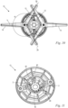
- the cutting head 10 comprises an interference contour 40 and a guide groove 41.
- the interference contour 40 is formed on the upper base body part 12.
- the guide groove 41 is formed on the lower base body part 13.
- the interference contour 40 can of course also be formed on the lower base body part 13 and the guide groove 41 on the upper base body part 12.
- the interference contour 40 is formed on the inner wall 37 of the upper base body part 12.
- the interference contour 40 is designed as a rib 42 extending in the axial direction, i.e. in the direction of the axis of rotation 17.
- a recess is provided in the middle of the rib 42.
- the ribs 42 protrude from the inner wall 37 of the upper base body part 12 into the central opening 36.
- two interference contours 40 are provided, which have the same angular distance from one another in the circumferential direction to the axis of rotation 17.
- the guide groove 41 is shown, which is formed on the dome 35 of the lower base body part 13.
- the guide groove 41 runs from the front side of the dome 35 in the direction of the axis of rotation 17 away from the front side of the dome 35.
- two guide grooves 41 are provided, which are arranged analogously to the interference contours 40 at equal angular distances in the circumferential direction to the axis of rotation 17.
- the number of guide grooves 41 on the dome 35 corresponds in the embodiment to the number of interference contours 40 on the inner wall 37 of the upper base body part 12. It can also be provided that there are fewer interference contours 40 than guide grooves 41.
- the interaction of the interference contour 40 and the guide groove 41 ensures that the upper base body part 12 and the lower base body part 13 can only be assembled in a predetermined position relative to one another.
- the base body parts 12, 13 must therefore be aligned with one another in the circumferential direction.
- the upper base body part 12 slides with its interference contour 40 along the front surface 47 of the mandrel 35 until the operator has aligned the base body parts 12, 13 with one another by twisting them in such a way that the interference contour 40 and the guide groove 41 are opposite one another in the direction of the axis of rotation 17.
- the upper base body part 12 has a collar 48 which protrudes in the axial direction over the interference element 40 and has a collar front side 49 which relieves the user of the radial alignment of the two base body parts 12, 13 with one another during twisting.
- the interference contour 40 is designed such that it can slide into the guide groove 41 and the base body parts 12, 13 can be pushed together.
- the snap connection 1 and the interference contour 40 or the guide groove 41 are coordinated with one another in such a way that when the base body parts 12 are pushed together, the interference contour 40 must first slide into the guide groove 41 before the gripping hooks 2 can penetrate into the holding opening 8. Due to the contact between the interference contour 40 and the guide groove 41, torques can be transmitted between the base body parts 12, 13 in the circumferential direction to the axis of rotation 17. This means that the base body parts 12, 13 can no longer be rotated relative to one another when the gripping hooks 2 penetrate into the holding opening 3 on the dome 35. Due to the interaction of the interference contour 40 and the guide groove 41, the base body parts 12, 13 are connected to one another in a rotationally fixed manner.
- the interference contour 40 and the guide groove 41 form a positive connection in the circumferential direction to the axis of rotation 17. This prevents unwanted Twisting of the base body parts 12, 13 by the operator is avoided. This prevents the gripping hooks 2 from breaking off during the assembly process of the cutting head 10. The gripping hooks 2 of the snap connection 1 are protected during assembly by the interference contour 40 and the guide groove 41.
- the thread of the screw element 19 has a thread length g measured in the direction of the axis of rotation 17.
- the upper base body part 12 has an axially measured total immersion depth h which corresponds to the distance between the collar front side 49 of the collar 48 and the front side 50 of the central opening 36.
- the interference contour 40 has an axially measured length i from the front side 50 of the central opening 36 to the front side of the interference contour 40.
- the gripping hook 2 has an immersion depth j which runs axially measured from the front side 50 of the central opening 36 to the end of the hook head 3.
- the total immersion depth h is greater than the length i of the interference contour 40, as a result of which when the base body parts 12, 13 are assembled, they are first guided radially through the collar 48.
- the length i of the interference contour 40 is greater than the immersion depth j of the gripping hook 2, whereby the interference contour 40 is first in engagement with the guide groove 41 and only then does the gripping hook 2 engage in the holding contour 4.
- the length i of the interference contour 40 is at least 120%, in particular 150%, preferably approximately 200% of the immersion depth j of the gripping hook 2.
- the interference contour j preferably corresponds approximately to the thread length g of the screw element 19.
- the interference contours 40 are located at half an angle, here 90°, between adjacent bearing pins 16. This is advantageous because the guide groove 41 forms part of the cutting line holder.
- the gripping hooks 2 are preferably arranged centrally between adjacent bearing pins 16 and interference contour 40. Depending on the structure of the base body part 12, 13 and corresponding stiffening ribs, the gripping hook 2 can also be arranged off-center between the bearing pin 16 and the interference contour 40.
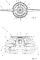
- a sectional view of the cutting head 10 is shown, in which the cutting tools 14 are pivoted out to the maximum.
- the pivot angle ⁇ results from the two opposing pivot stops of the base body 11 for a corresponding cutting tool 14.
- the maximum swivel angle ⁇ of the cutting tool 14 is shown, which is measured in the circumferential direction to the bearing pin 16 from the longitudinal axis 29 of the cutting tool 14.
- the swivel angle ⁇ is preferably at least 60°, preferably at least 120°, in particular approximately 200°.
- the swivel plane of the cutting tool 14 is arranged perpendicular to the axis of rotation 17. As in Fig.
- the snap connection 1 has a distance a measured in the radial direction to the axis of rotation 17, which is at most 40%, preferably at most 30%, in particular 25% of the diameter d of the cutting head 10.
- the bearing axis 32 has a distance f to the axis of rotation 17.
- the distance f between the bearing axis 32 and the axis of rotation 17 is greater than the distance a between the snap connection 1 and the axis of rotation 17 (see Fig. 12 ).
- the snap connection 1 is located in the radial direction to the axis of rotation 17 within the bearing axes 32 of the bearing bolts 16.
- the cutting tool 14 has a length b measured in its longitudinal direction, wherein the length b corresponds to at least 60% of the diameter d of the cutting head 10. In an alternative embodiment of the cutting head 10, the length b of the cutting blade 14 can also be shorter.
Landscapes
- Life Sciences & Earth Sciences (AREA)
- Environmental Sciences (AREA)
- Harvester Elements (AREA)
Claims (15)
- Tête de coupe pour une débroussailleuse,comprenant un corps de base divisé (11) avec une partie de corps de base supérieure (12) et une partie de corps de base inférieure (13),un élément vissable (19) étant agencé sur la partie inférieure du corps de base (13),l'élément vissable (19) servant à une fixation sur un arbre d'entraînement (18) que comprend une débroussailleuse,au moins un logement (15) pour la fixation d'un outil de coupe (14) étant prévu entre la partie supérieure du corps de base (12) et la partie inférieure du corps de base (13),le corps de base (11) étant apte à être entraîné en rotation autour de son axe de rotation (17) lors du fonctionnement d'une débroussailleuse,la partie supérieure du corps de base (12) et la partie inférieure du corps de base (13) étant maintenues l'une par rapport à l'autre au moyen d'un assemblage par encliquetage (1) libérable,caractérisée en ce que l'assemblage par encliquetage (1) présente une distance (a), mesurée dans la direction radiale par rapport à l'axe de rotation (17), qui représente au maximum 40% du diamètre (d) de la tête de coupe (10).
- Tête de coupe selon la revendication 1,
caractérisée en ce que l'assemblage par encliquetage (1) présente une distance (a) mesurée dans la direction radiale par rapport à l'axe de rotation (17), qui représente au maximum 30%, de préférence au maximum 25%, du diamètre (d) de la tête de coupe (10). - Tête de coupe selon la revendication 2,
caractérisée en ce que le logement (15) présente un axe de palier (32) s'étendant dans la direction de l'axe de rotation (17), l'axe de palier (32) étant à une distance (f) de l'axe de rotation (17) et la distance (f) entre l'axe de palier (32) et l'axe de rotation (17) étant supérieure à la distance (a) entre l'assemblage par encliquetage (1) et l'axe de rotation (17). - Tête de coupe selon l'une des revendications 1 à 3,
caractérisée en ce que l'assemblage par encliquetage (1) comprend au moins un crochet de préhension (2), et au moins un contour de retenue (4) en liaison active avec le crochet de préhension (2). - Tête de coupe selon la revendication 4,
caractérisée en ce que le crochet de préhension (2) est agencé sur la partie supérieure du corps de base (12) et ledit au moins un contour de retenue (4) sur la partie inférieure du corps de base (13). - Tête de coupe selon la revendication 4 ou la revendication 5,
caractérisée en ce que ledit au moins un crochet de préhension (2) présente une tête de crochet (3) qui est conçue pour saisir par l'arrière ledit au moins un contour de retenue (4). - Tête de coupe selon la revendication 6,
caractérisée en ce que la tête de crochet (3) est conçue de telle sorte que l'assemblage par encliquetage (1) s'enclenche lorsque les parties de corps de base (12, 13) sont pressées l'une contre l'autre et se désenclenche lorsque les parties de corps de base (12, 13) sont séparées. - Tête de coupe selon l'une des revendications 1 à 7,
caractérisée en ce qu'il est prévu un contour d'interférence (40) sur l'une des deux parties de corps de base (12, 13) et, sur l'autre partie de corps de base (12, 13), une rainure de guidage (41) coopérant avec le contour d'interférence (40) et s'étendant dans la direction de l'axe de rotation (17), afin d'aligner l'une par rapport à l'autre la partie de corps de base supérieure (12) et la partie de corps de base inférieure (13) au moyen du contour d'interférence (40) et de la rainure de guidage (41) dans la direction périphérique de l'axe de rotation (17). - Tête de coupe selon la revendication 8,
caractérisée en ce que l'assemblage par encliquetage (1) est conçu de telle sorte que l'assemblage par encliquetage (1) ne peut être enclenché que lorsque la partie supérieure du corps de base (12) et la partie inférieure du corps de base (13) sont alignées l'une par rapport à l'autre par le biais du contour d'interférence (40) et de la rainure de guidage (41). - Tête de coupe selon la revendication 8 ou la revendication 9,
caractérisée en ce que des couples de rotation sont aptes à être transmis dans la direction circonférentielle entre la partie de corps de base supérieure (12) et la partie de corps de base inférieure (13) par le biais du contour d'interférence (40) et de la rainure de guidage (41). - Tête de coupe selon l'une des revendications 1 à 10,
caractérisée en ce que le logement (15) est réalisé sous la forme d'un goujon (16) formant palier, et un outil de coupe (14) est apte à être agencé sur le corps de base (11) au moyen du goujon (16) formant palier. - Tête de coupe selon l'une des revendications 1 à 11,
caractérisée en ce que le goujon (16) formant palier est fixé d'un côté à la partie supérieure du corps de base (12) ou à la partie inférieure du corps de base (13). - Tête de coupe selon la revendication 11 ou la revendication 12,
caractérisée en ce que le goujon (16) formant palier est fixé à la partie supérieure du corps de base (12). - Tête de coupe selon l'une des revendications 1 à 13,
caractérisée en ce que l'élément vissable (19) est agencé de manière non tournante sur la partie inférieure du corps de base (13). - Tête de coupe selon l'une des revendications 1 à 14,
caractérisée en ce qu'un outil de coupe (14) est agencé de manière pivotante sur ledit au moins un logement (15).
Priority Applications (3)
| Application Number | Priority Date | Filing Date | Title |
|---|---|---|---|
| EP20180105.7A EP3925427B1 (fr) | 2020-06-15 | 2020-06-15 | Tête de coupe pour une débroussailleuse |
| US17/338,760 US12029159B2 (en) | 2020-06-15 | 2021-06-04 | Cutter head for a brush cutter |
| CN202110660233.4A CN113796197B (zh) | 2020-06-15 | 2021-06-15 | 用于机动镰刀的切割头 |
Applications Claiming Priority (1)
| Application Number | Priority Date | Filing Date | Title |
|---|---|---|---|
| EP20180105.7A EP3925427B1 (fr) | 2020-06-15 | 2020-06-15 | Tête de coupe pour une débroussailleuse |
Publications (2)
| Publication Number | Publication Date |
|---|---|
| EP3925427A1 EP3925427A1 (fr) | 2021-12-22 |
| EP3925427B1 true EP3925427B1 (fr) | 2025-01-15 |
Family
ID=71103216
Family Applications (1)
| Application Number | Title | Priority Date | Filing Date |
|---|---|---|---|
| EP20180105.7A Active EP3925427B1 (fr) | 2020-06-15 | 2020-06-15 | Tête de coupe pour une débroussailleuse |
Country Status (3)
| Country | Link |
|---|---|
| US (1) | US12029159B2 (fr) |
| EP (1) | EP3925427B1 (fr) |
| CN (1) | CN113796197B (fr) |
Families Citing this family (7)
| Publication number | Priority date | Publication date | Assignee | Title |
|---|---|---|---|---|
| USD992989S1 (en) * | 2022-02-11 | 2023-07-25 | Aero-Flex Technologies, Inc. | Trimmer line blade |
| USD1013469S1 (en) * | 2019-03-28 | 2024-02-06 | Aero-Flex Technologies, Inc. | Trimmer line blade |
| CA3116938C (fr) * | 2021-05-03 | 2022-10-18 | Great Plains Restoration Solutions Inc. | Recolteuse manuelle pour recolter les graines de plantes |
| CN115529922B (zh) * | 2021-06-29 | 2026-02-03 | 株式会社牧田 | 接地体和具备接地体的割草机 |
| USD1015094S1 (en) * | 2022-02-11 | 2024-02-20 | Aero-Flex Technologies, Inc. | Trimmer conversion component |
| USD1002307S1 (en) * | 2022-02-11 | 2023-10-24 | Aero-Flex Technologies, Inc. | Trimmer conversion component |
| SE547282C2 (en) * | 2022-07-04 | 2025-06-17 | Husqvarna Ab | Protection plate |
Family Cites Families (23)
| Publication number | Priority date | Publication date | Assignee | Title |
|---|---|---|---|---|
| CA1079075A (fr) * | 1976-07-19 | 1980-06-10 | George C. Ballas | Couteau rotatif |
| US4172322A (en) * | 1976-07-19 | 1979-10-30 | Weed Eater, Inc. | Rotary cutting assembly |
| US4089114A (en) * | 1976-08-31 | 1978-05-16 | Disston, Inc. | Cutting device |
| US4205510A (en) * | 1978-07-07 | 1980-06-03 | Raniero John J | Safety lawn mower |
| US4300336A (en) * | 1979-09-10 | 1981-11-17 | Echo, Incorporated | Cutter blade assembly for weed and grass trimmers |
| US4413468A (en) * | 1982-04-02 | 1983-11-08 | Hoffco, Inc. | Lawn mower blade retainer |
| US5881540A (en) * | 1996-01-29 | 1999-03-16 | Mtd Products Inc. | Mounting member for mower blade spindle |
| US6119350A (en) * | 1997-05-23 | 2000-09-19 | Trim-A-Lawn Corporation | Rotary cutting member for lawn trimmers |
| US6112416A (en) * | 1997-12-16 | 2000-09-05 | Bridges; Roy | Weed and grass trimmer attachment head |
| US20020073556A1 (en) * | 2000-12-15 | 2002-06-20 | Robert L. Phillips | Top loading fixed line trimmer head |
| DE10219180B4 (de) * | 2002-04-29 | 2004-05-27 | Mogatec Moderne Gartentechnik Gmbh | Messerträger für einen rotierenden Schneidkopf einer Pflanzenschneidvorrichtung |
| US8510960B2 (en) * | 2006-09-01 | 2013-08-20 | Proulx Manufacturing, Inc. | Trimmer head spool for use in flexible line rotary trimmer heads having improved line loading mechanism |
| ITFI20060275A1 (it) * | 2006-11-03 | 2008-05-04 | Arnetoli Motor | Testina tosaerba a filo |
| WO2008137061A1 (fr) * | 2007-05-01 | 2008-11-13 | Torvian, Inc. | Tête de taille-bordures à brin fixe se démontant par le sommet |
| US9603301B2 (en) * | 2007-08-10 | 2017-03-28 | Orlando Jerez | Weed trimming apparatus, weed trimmer head, and trimmer line retention device |
| US9642302B2 (en) * | 2010-06-01 | 2017-05-09 | Orlando Jerez | Rotary trimmer apparatus and related rotary head assembly |
| JP3181518U (ja) * | 2012-10-26 | 2013-02-14 | 呉輝毅 | 直接駆動式電動草刈り機 |
| US20140150267A1 (en) * | 2012-12-03 | 2014-06-05 | Techtronic Outdoor Products Technology Limited | Head for a trimmer and attachment therefor |
| US10278327B2 (en) * | 2014-05-09 | 2019-05-07 | Shakespeare Company, Llc | Trimmer head for use with line and blades |
| EP3360405B1 (fr) * | 2017-02-08 | 2021-04-14 | Andreas Stihl AG & Co. KG | Tête de coupe pour une débroussailleuse |
| US11122735B2 (en) * | 2017-09-12 | 2021-09-21 | Milwaukee Electric Tool Corporation | String trimmer head and spool |
| US10939614B2 (en) * | 2017-11-03 | 2021-03-09 | Mtd Products Inc | Trimmer head |
| CN111102411A (zh) * | 2018-10-26 | 2020-05-05 | 瑞肯耐特流体控制系统(镇江)有限公司 | 快速连接器、滑动锁及套接部件 |
-
2020
- 2020-06-15 EP EP20180105.7A patent/EP3925427B1/fr active Active
-
2021
- 2021-06-04 US US17/338,760 patent/US12029159B2/en active Active
- 2021-06-15 CN CN202110660233.4A patent/CN113796197B/zh active Active
Also Published As
| Publication number | Publication date |
|---|---|
| US12029159B2 (en) | 2024-07-09 |
| US20210386014A1 (en) | 2021-12-16 |
| CN113796197A (zh) | 2021-12-17 |
| CN113796197B (zh) | 2025-03-07 |
| EP3925427A1 (fr) | 2021-12-22 |
Similar Documents
| Publication | Publication Date | Title |
|---|---|---|
| EP3925427B1 (fr) | Tête de coupe pour une débroussailleuse | |
| EP2997810B1 (fr) | Appareil de travail | |
| DE60209642T2 (de) | Trimmerkopf mit fixiertem Schneidfaden mit automatischer Ladung | |
| EP3360405B1 (fr) | Tête de coupe pour une débroussailleuse | |
| DE19827335A1 (de) | Handgeführte Motorarbeitsmaschine | |
| DE102007059905A1 (de) | Scheibenwischerantrieb | |
| DE19623921A1 (de) | Lagerprofil für eine Antriebswelle | |
| DE202013007005U1 (de) | Welle zur Drehkopplung einer Hauptvorrichtung mit einer rohrförmigen Vorrichtung | |
| DE3153605C2 (fr) | ||
| EP1029436B1 (fr) | Fixation, faucheuse et véhicule resp. appareil de travail | |
| DE602004003470T2 (de) | Schneidkopf für freischneidegerät, kantentrimmer oder dergleichen | |
| DE2556553A1 (de) | Schneidkopf fuer ein freischneidegeraet | |
| DE29916682U1 (de) | Anordnung zur Sicherung eines Bauteils | |
| EP3272207B1 (fr) | Appareil de travail comprenant des boîtiers partiels reliés par une articulation pivotante | |
| DE102005035024A1 (de) | Schutzschild für einen Freischneider | |
| DE102004063723A1 (de) | Schutzschild für ein Schneidwerkzeug eines Freischneiders | |
| EP3785518B1 (fr) | Tête de faucheuse à monter sur un arbre d'entraînement d'une débroussailleuse | |
| DE2905363C2 (de) | Scherbolzenkupplung | |
| DE10219180B4 (de) | Messerträger für einen rotierenden Schneidkopf einer Pflanzenschneidvorrichtung | |
| DE19910793B4 (de) | Arbeitsgerät | |
| EP3222861B1 (fr) | Tube de protection destine a loger un arbre d'entrainement d'un appareil de travail portatif | |
| EP0047961B1 (fr) | Accouplement de rotule d'attelage pour véhicules moteur | |
| DE102007007242B4 (de) | Mähmaschine | |
| DE102014201519B4 (de) | Mähgerat | |
| EP4289251A1 (fr) | Ensemble d'une tête de tonte, d'un arbre de sortie destiné au logement d'une tête de tonte, et d'un dispositif de fixation destiné à la fixation de la tête de tonte sur l'arbre de sortie, ainsi qu'appareil de travail doté d'un tel ensemble |
Legal Events
| Date | Code | Title | Description |
|---|---|---|---|
| PUAI | Public reference made under article 153(3) epc to a published international application that has entered the european phase |
Free format text: ORIGINAL CODE: 0009012 |
|
| STAA | Information on the status of an ep patent application or granted ep patent |
Free format text: STATUS: THE APPLICATION HAS BEEN PUBLISHED |
|
| AK | Designated contracting states |
Kind code of ref document: A1 Designated state(s): AL AT BE BG CH CY CZ DE DK EE ES FI FR GB GR HR HU IE IS IT LI LT LU LV MC MK MT NL NO PL PT RO RS SE SI SK SM TR |
|
| B565 | Issuance of search results under rule 164(2) epc |
Effective date: 20201116 |
|
| STAA | Information on the status of an ep patent application or granted ep patent |
Free format text: STATUS: REQUEST FOR EXAMINATION WAS MADE |
|
| 17P | Request for examination filed |
Effective date: 20220614 |
|
| RBV | Designated contracting states (corrected) |
Designated state(s): AL AT BE BG CH CY CZ DE DK EE ES FI FR GB GR HR HU IE IS IT LI LT LU LV MC MK MT NL NO PL PT RO RS SE SI SK SM TR |
|
| GRAP | Despatch of communication of intention to grant a patent |
Free format text: ORIGINAL CODE: EPIDOSNIGR1 |
|
| STAA | Information on the status of an ep patent application or granted ep patent |
Free format text: STATUS: GRANT OF PATENT IS INTENDED |
|
| INTG | Intention to grant announced |
Effective date: 20240821 |
|
| GRAS | Grant fee paid |
Free format text: ORIGINAL CODE: EPIDOSNIGR3 |
|
| GRAA | (expected) grant |
Free format text: ORIGINAL CODE: 0009210 |
|
| STAA | Information on the status of an ep patent application or granted ep patent |
Free format text: STATUS: THE PATENT HAS BEEN GRANTED |
|
| AK | Designated contracting states |
Kind code of ref document: B1 Designated state(s): AL AT BE BG CH CY CZ DE DK EE ES FI FR GB GR HR HU IE IS IT LI LT LU LV MC MK MT NL NO PL PT RO RS SE SI SK SM TR |
|
| REG | Reference to a national code |
Ref country code: CH Ref legal event code: EP Ref country code: GB Ref legal event code: FG4D Free format text: NOT ENGLISH |
|
| REG | Reference to a national code |
Ref country code: DE Ref legal event code: R096 Ref document number: 502020010192 Country of ref document: DE |
|
| REG | Reference to a national code |
Ref country code: IE Ref legal event code: FG4D Free format text: LANGUAGE OF EP DOCUMENT: GERMAN |
|
| REG | Reference to a national code |
Ref country code: NL Ref legal event code: MP Effective date: 20250115 |
|
| PG25 | Lapsed in a contracting state [announced via postgrant information from national office to epo] |
Ref country code: NL Free format text: LAPSE BECAUSE OF FAILURE TO SUBMIT A TRANSLATION OF THE DESCRIPTION OR TO PAY THE FEE WITHIN THE PRESCRIBED TIME-LIMIT Effective date: 20250115 |
|
| PG25 | Lapsed in a contracting state [announced via postgrant information from national office to epo] |
Ref country code: RS Free format text: LAPSE BECAUSE OF FAILURE TO SUBMIT A TRANSLATION OF THE DESCRIPTION OR TO PAY THE FEE WITHIN THE PRESCRIBED TIME-LIMIT Effective date: 20250415 |
|
| PG25 | Lapsed in a contracting state [announced via postgrant information from national office to epo] |
Ref country code: FI Free format text: LAPSE BECAUSE OF FAILURE TO SUBMIT A TRANSLATION OF THE DESCRIPTION OR TO PAY THE FEE WITHIN THE PRESCRIBED TIME-LIMIT Effective date: 20250115 |
|
| PG25 | Lapsed in a contracting state [announced via postgrant information from national office to epo] |
Ref country code: PL Free format text: LAPSE BECAUSE OF FAILURE TO SUBMIT A TRANSLATION OF THE DESCRIPTION OR TO PAY THE FEE WITHIN THE PRESCRIBED TIME-LIMIT Effective date: 20250115 |
|
| PG25 | Lapsed in a contracting state [announced via postgrant information from national office to epo] |
Ref country code: ES Free format text: LAPSE BECAUSE OF FAILURE TO SUBMIT A TRANSLATION OF THE DESCRIPTION OR TO PAY THE FEE WITHIN THE PRESCRIBED TIME-LIMIT Effective date: 20250115 |
|
| REG | Reference to a national code |
Ref country code: LT Ref legal event code: MG9D |
|
| PG25 | Lapsed in a contracting state [announced via postgrant information from national office to epo] |
Ref country code: IS Free format text: LAPSE BECAUSE OF FAILURE TO SUBMIT A TRANSLATION OF THE DESCRIPTION OR TO PAY THE FEE WITHIN THE PRESCRIBED TIME-LIMIT Effective date: 20250515 Ref country code: NO Free format text: LAPSE BECAUSE OF FAILURE TO SUBMIT A TRANSLATION OF THE DESCRIPTION OR TO PAY THE FEE WITHIN THE PRESCRIBED TIME-LIMIT Effective date: 20250415 |
|
| PG25 | Lapsed in a contracting state [announced via postgrant information from national office to epo] |
Ref country code: HR Free format text: LAPSE BECAUSE OF FAILURE TO SUBMIT A TRANSLATION OF THE DESCRIPTION OR TO PAY THE FEE WITHIN THE PRESCRIBED TIME-LIMIT Effective date: 20250115 |
|
| PG25 | Lapsed in a contracting state [announced via postgrant information from national office to epo] |
Ref country code: LV Free format text: LAPSE BECAUSE OF FAILURE TO SUBMIT A TRANSLATION OF THE DESCRIPTION OR TO PAY THE FEE WITHIN THE PRESCRIBED TIME-LIMIT Effective date: 20250115 Ref country code: PT Free format text: LAPSE BECAUSE OF FAILURE TO SUBMIT A TRANSLATION OF THE DESCRIPTION OR TO PAY THE FEE WITHIN THE PRESCRIBED TIME-LIMIT Effective date: 20250515 |
|
| PG25 | Lapsed in a contracting state [announced via postgrant information from national office to epo] |
Ref country code: BG Free format text: LAPSE BECAUSE OF FAILURE TO SUBMIT A TRANSLATION OF THE DESCRIPTION OR TO PAY THE FEE WITHIN THE PRESCRIBED TIME-LIMIT Effective date: 20250115 Ref country code: GR Free format text: LAPSE BECAUSE OF FAILURE TO SUBMIT A TRANSLATION OF THE DESCRIPTION OR TO PAY THE FEE WITHIN THE PRESCRIBED TIME-LIMIT Effective date: 20250416 |
|
| PG25 | Lapsed in a contracting state [announced via postgrant information from national office to epo] |
Ref country code: SE Free format text: LAPSE BECAUSE OF FAILURE TO SUBMIT A TRANSLATION OF THE DESCRIPTION OR TO PAY THE FEE WITHIN THE PRESCRIBED TIME-LIMIT Effective date: 20250115 |
|
| PG25 | Lapsed in a contracting state [announced via postgrant information from national office to epo] |
Ref country code: SM Free format text: LAPSE BECAUSE OF FAILURE TO SUBMIT A TRANSLATION OF THE DESCRIPTION OR TO PAY THE FEE WITHIN THE PRESCRIBED TIME-LIMIT Effective date: 20250115 |
|
| PG25 | Lapsed in a contracting state [announced via postgrant information from national office to epo] |
Ref country code: DK Free format text: LAPSE BECAUSE OF FAILURE TO SUBMIT A TRANSLATION OF THE DESCRIPTION OR TO PAY THE FEE WITHIN THE PRESCRIBED TIME-LIMIT Effective date: 20250115 |
|
| PG25 | Lapsed in a contracting state [announced via postgrant information from national office to epo] |
Ref country code: IT Free format text: LAPSE BECAUSE OF FAILURE TO SUBMIT A TRANSLATION OF THE DESCRIPTION OR TO PAY THE FEE WITHIN THE PRESCRIBED TIME-LIMIT Effective date: 20250115 |
|
| REG | Reference to a national code |
Ref country code: DE Ref legal event code: R097 Ref document number: 502020010192 Country of ref document: DE |
|
| PG25 | Lapsed in a contracting state [announced via postgrant information from national office to epo] |
Ref country code: CZ Free format text: LAPSE BECAUSE OF FAILURE TO SUBMIT A TRANSLATION OF THE DESCRIPTION OR TO PAY THE FEE WITHIN THE PRESCRIBED TIME-LIMIT Effective date: 20250115 Ref country code: EE Free format text: LAPSE BECAUSE OF FAILURE TO SUBMIT A TRANSLATION OF THE DESCRIPTION OR TO PAY THE FEE WITHIN THE PRESCRIBED TIME-LIMIT Effective date: 20250115 |
|
| PG25 | Lapsed in a contracting state [announced via postgrant information from national office to epo] |
Ref country code: RO Free format text: LAPSE BECAUSE OF FAILURE TO SUBMIT A TRANSLATION OF THE DESCRIPTION OR TO PAY THE FEE WITHIN THE PRESCRIBED TIME-LIMIT Effective date: 20250115 |
|
| PG25 | Lapsed in a contracting state [announced via postgrant information from national office to epo] |
Ref country code: SK Free format text: LAPSE BECAUSE OF FAILURE TO SUBMIT A TRANSLATION OF THE DESCRIPTION OR TO PAY THE FEE WITHIN THE PRESCRIBED TIME-LIMIT Effective date: 20250115 |
|
| PLBE | No opposition filed within time limit |
Free format text: ORIGINAL CODE: 0009261 |
|
| STAA | Information on the status of an ep patent application or granted ep patent |
Free format text: STATUS: NO OPPOSITION FILED WITHIN TIME LIMIT |
|
| REG | Reference to a national code |
Ref country code: CH Ref legal event code: L10 Free format text: ST27 STATUS EVENT CODE: U-0-0-L10-L00 (AS PROVIDED BY THE NATIONAL OFFICE) Effective date: 20251126 |
|
| 26N | No opposition filed |
Effective date: 20251016 |
|
| PGFP | Annual fee paid to national office [announced via postgrant information from national office to epo] |
Ref country code: FR Payment date: 20251222 Year of fee payment: 6 |
|
| REG | Reference to a national code |
Ref country code: CH Ref legal event code: H13 Free format text: ST27 STATUS EVENT CODE: U-0-0-H10-H13 (AS PROVIDED BY THE NATIONAL OFFICE) Effective date: 20260127 |
|
| PG25 | Lapsed in a contracting state [announced via postgrant information from national office to epo] |
Ref country code: MC Free format text: LAPSE BECAUSE OF FAILURE TO SUBMIT A TRANSLATION OF THE DESCRIPTION OR TO PAY THE FEE WITHIN THE PRESCRIBED TIME-LIMIT Effective date: 20250115 |
|
| PG25 | Lapsed in a contracting state [announced via postgrant information from national office to epo] |
Ref country code: LU Free format text: LAPSE BECAUSE OF NON-PAYMENT OF DUE FEES Effective date: 20250615 |
|
| GBPC | Gb: european patent ceased through non-payment of renewal fee |
Effective date: 20250615 |
|
| REG | Reference to a national code |
Ref country code: BE Ref legal event code: MM Effective date: 20250630 |
|
| PG25 | Lapsed in a contracting state [announced via postgrant information from national office to epo] |
Ref country code: GB Free format text: LAPSE BECAUSE OF NON-PAYMENT OF DUE FEES Effective date: 20250615 |
|
| PG25 | Lapsed in a contracting state [announced via postgrant information from national office to epo] |
Ref country code: IE Free format text: LAPSE BECAUSE OF NON-PAYMENT OF DUE FEES Effective date: 20250615 |
|
| PGFP | Annual fee paid to national office [announced via postgrant information from national office to epo] |
Ref country code: DE Payment date: 20251229 Year of fee payment: 6 |
|
| PG25 | Lapsed in a contracting state [announced via postgrant information from national office to epo] |
Ref country code: BE Free format text: LAPSE BECAUSE OF NON-PAYMENT OF DUE FEES Effective date: 20250630 |
|
| PG25 | Lapsed in a contracting state [announced via postgrant information from national office to epo] |
Ref country code: CH Free format text: LAPSE BECAUSE OF NON-PAYMENT OF DUE FEES Effective date: 20250630 |