EP3925537A1 - Procédé et système de traitement de signal d'électroencéphalogramme - Google Patents
Procédé et système de traitement de signal d'électroencéphalogramme Download PDFInfo
- Publication number
- EP3925537A1 EP3925537A1 EP20187999.6A EP20187999A EP3925537A1 EP 3925537 A1 EP3925537 A1 EP 3925537A1 EP 20187999 A EP20187999 A EP 20187999A EP 3925537 A1 EP3925537 A1 EP 3925537A1
- Authority
- EP
- European Patent Office
- Prior art keywords
- waveform
- spike
- complexity
- distribution
- eeg signal
- Prior art date
- Legal status (The legal status is an assumption and is not a legal conclusion. Google has not performed a legal analysis and makes no representation as to the accuracy of the status listed.)
- Granted
Links
Images



Classifications
-
- A—HUMAN NECESSITIES
- A61—MEDICAL OR VETERINARY SCIENCE; HYGIENE
- A61B—DIAGNOSIS; SURGERY; IDENTIFICATION
- A61B5/00—Measuring for diagnostic purposes; Identification of persons
- A61B5/40—Detecting, measuring or recording for evaluating the nervous system
- A61B5/4076—Diagnosing or monitoring particular conditions of the nervous system
- A61B5/4094—Diagnosing or monitoring seizure diseases, e.g. epilepsy
-
- A—HUMAN NECESSITIES
- A61—MEDICAL OR VETERINARY SCIENCE; HYGIENE
- A61B—DIAGNOSIS; SURGERY; IDENTIFICATION
- A61B5/00—Measuring for diagnostic purposes; Identification of persons
- A61B5/24—Detecting, measuring or recording bioelectric or biomagnetic signals of the body or parts thereof
- A61B5/316—Modalities, i.e. specific diagnostic methods
- A61B5/369—Electroencephalography [EEG]
- A61B5/372—Analysis of electroencephalograms
-
- A—HUMAN NECESSITIES
- A61—MEDICAL OR VETERINARY SCIENCE; HYGIENE
- A61B—DIAGNOSIS; SURGERY; IDENTIFICATION
- A61B5/00—Measuring for diagnostic purposes; Identification of persons
- A61B5/24—Detecting, measuring or recording bioelectric or biomagnetic signals of the body or parts thereof
- A61B5/316—Modalities, i.e. specific diagnostic methods
- A61B5/369—Electroencephalography [EEG]
- A61B5/372—Analysis of electroencephalograms
- A61B5/374—Detecting the frequency distribution of signals, e.g. detecting delta, theta, alpha, beta or gamma waves
-
- A—HUMAN NECESSITIES
- A61—MEDICAL OR VETERINARY SCIENCE; HYGIENE
- A61B—DIAGNOSIS; SURGERY; IDENTIFICATION
- A61B5/00—Measuring for diagnostic purposes; Identification of persons
- A61B5/72—Signal processing specially adapted for physiological signals or for diagnostic purposes
- A61B5/7203—Signal processing specially adapted for physiological signals or for diagnostic purposes for noise prevention, reduction or removal
-
- A—HUMAN NECESSITIES
- A61—MEDICAL OR VETERINARY SCIENCE; HYGIENE
- A61B—DIAGNOSIS; SURGERY; IDENTIFICATION
- A61B5/00—Measuring for diagnostic purposes; Identification of persons
- A61B5/72—Signal processing specially adapted for physiological signals or for diagnostic purposes
- A61B5/7225—Details of analogue processing, e.g. isolation amplifier, gain or sensitivity adjustment, filtering, baseline or drift compensation
-
- A—HUMAN NECESSITIES
- A61—MEDICAL OR VETERINARY SCIENCE; HYGIENE
- A61B—DIAGNOSIS; SURGERY; IDENTIFICATION
- A61B5/00—Measuring for diagnostic purposes; Identification of persons
- A61B5/72—Signal processing specially adapted for physiological signals or for diagnostic purposes
- A61B5/7235—Details of waveform analysis
-
- A—HUMAN NECESSITIES
- A61—MEDICAL OR VETERINARY SCIENCE; HYGIENE
- A61B—DIAGNOSIS; SURGERY; IDENTIFICATION
- A61B5/00—Measuring for diagnostic purposes; Identification of persons
- A61B5/72—Signal processing specially adapted for physiological signals or for diagnostic purposes
- A61B5/7271—Specific aspects of physiological measurement analysis
- A61B5/7282—Event detection, e.g. detecting unique waveforms indicative of a medical condition
-
- G—PHYSICS
- G16—INFORMATION AND COMMUNICATION TECHNOLOGY [ICT] SPECIALLY ADAPTED FOR SPECIFIC APPLICATION FIELDS
- G16H—HEALTHCARE INFORMATICS, i.e. INFORMATION AND COMMUNICATION TECHNOLOGY [ICT] SPECIALLY ADAPTED FOR THE HANDLING OR PROCESSING OF MEDICAL OR HEALTHCARE DATA
- G16H50/00—ICT specially adapted for medical diagnosis, medical simulation or medical data mining; ICT specially adapted for detecting, monitoring or modelling epidemics or pandemics
- G16H50/30—ICT specially adapted for medical diagnosis, medical simulation or medical data mining; ICT specially adapted for detecting, monitoring or modelling epidemics or pandemics for calculating health indices; for individual health risk assessment
Definitions
- the disclosure relates to a method for processing a signal, and in particular to a method for processing an electroencephalography (EEG) signal.
- EEG electroencephalography
- EEG electrocorticography
- EEG electroencephalography
- the signals of ECoG and EEG are commonly known as brainwave signals, and the two principles for generating the signals are almost the same.
- the difference between an ECoG signal and an EEG signal is that the measurement of the ECoG signal uses a semi-invasive method in which the skull of a patient is opened and electrodes are laid flat on the cerebral cortex and under the subdural, and the measurement of the EEG signal uses a non-invasive method in which the brainwave is measured on the scalp.
- the brainwave signals are most commonly used to diagnose epilepsy.
- epilepsy may be roughly divided into the following stages: inter-ictal, pre-ictal, irregular phase, and bursting phase.
- the stage between two seizures is referred to as “inter-ictal”, and “pre-ictal”, “irregular phase”, and “bursting phase” belong to ictal phase of epilepsy onset.
- the irregular phase is of great significance for diagnosis and evaluation of epilepsy, but conventional algorithms are less able to effectively detect such characteristics.
- the reason is that the neurophysiological performance and the complex interaction between excitatory cells and suppressor cells enable the brainwave signals to exhibit non-stationary characteristics, such that the brainwave signals exhibit irregular frequency and irregular amplitude changes, which are difficult for conventional algorithm determination models to accurately interpret.
- the disclosure provides a method and a system for processing an electroencephalography (EEG) signal, which can accurately find a specified neural waveform in the EEG signal.
- EEG electroencephalography
- the method for processing the EEG signal of the disclosure performs the following steps through a processor.
- the EEG signal is obtained.
- a spike detection is performed on the EEG signal to obtain a spike distribution waveform.
- An instantaneous frequency oscillation energy analysis is performed on the EEG signal to obtain multiple energy distribution waveforms.
- a complexity analysis is performed on the EEG signal to obtain a complexity change waveform.
- a determination result of a specified neural waveform is obtained based on the spike distribution waveform, the energy distribution waveforms, and the complexity change waveform, wherein the determination result includes a time interval.
- a waveform in the time interval of the spike distribution waveform conforms to a spike distribution rule of the specified neural waveform.
- a waveform in the time interval of each energy distribution waveform conforms to an energy change rule of the specified neural waveform.
- a waveform in the time interval of the complexity change waveform conforms to a complexity change rule of the specified neural waveform.
- the step of performing the spike detection on the EEG signal to obtain the spike distribution waveform includes the following steps.
- the EEG signal is divided into multiple sampling intervals using a window width.
- a spike number included in each sampling interval is detected.
- the spike number included in each sampling interval is recorded following a time series, thereby obtaining the spike distribution waveform.
- the method further includes the following steps. Whether spike numbers in multiple unit intervals of the spike distribution waveform conform to the spike distribution rule is determined. In two adjacent unit intervals in a time series, if a spike number in a later unit interval decreases compared with a spike number in an earlier unit interval, the later unit interval is determined as conforming to the spike distribution rule.
- the step of performing the instantaneous frequency oscillation energy analysis on the EEG signal to obtain the energy distribution waveforms includes the following steps.
- An empirical mode decomposition (EMD) is performed on the EEG signal to obtain multiple intrinsic mode signals.
- An instantaneous frequency of each intrinsic mode signal in each of multiple sampling intervals is calculated to record the instantaneous frequency corresponding to each sampling interval following a time series in an instantaneous frequency distribution diagram corresponding to each intrinsic mode signal, thereby obtaining multiple instantaneous frequency distribution waveforms respectively corresponding to the multiple intrinsic mode signals.
- An energy calculation is respectively performed on the multiple instantaneous frequency signals to obtain the multiple energy distribution waveforms.
- the method further includes the following steps. Whether an energy density of each energy distribution waveform in multiple unit intervals conforms to the energy change rule is determined. In two adjacent unit intervals in a time series of each of the energy distribution waveforms at the same time, if an energy density in a later unit interval decreases compared with an energy density in an earlier unit interval, the later unit interval is determined as conforming to the energy change rule.
- the step of performing the complexity analysis on the EEG signal to obtain the complexity change waveform includes the following steps.
- the EEG signal is divided into multiple sampling intervals using a window width.
- a complexity of each sampling interval is calculated.
- the complexity corresponding to each sampling interval is recorded following a time series, thereby obtaining a complexity waveform.
- the complexity waveform is divided into multiple calculation intervals using another window width.
- a spike number included in each calculation interval is detected.
- the spike number included in each calculation interval is recorded following a time series, thereby obtaining the complexity change waveform.
- the method further includes the following step. Whether spike numbers in multiple unit intervals of the complexity change waveform conforms to the complexity change rule is determined. A unit interval in which the spike number is greater than a preset value is determined as conforming to the complexity change rule.
- the specified neural waveform is an irregular phase waveform for determining epilepsy onset.
- the system for processing an EEG signal of the disclosure includes: an output device, a storage device, and a processor.
- the storage device includes multiple code fragments.
- the processor is coupled to the output device and the storage device.
- the processor performs the code fragments to: obtain the EEG signal; perform a spike detection on the EEG signal to obtain a spike distribution waveform; perform an instantaneous frequency oscillation energy analysis on the EEG signal to obtain multiple energy distribution waveforms; perform a complexity analysis on the EEG signal to obtain a complexity change waveform; and obtain a determination result of a specified neural waveform based on the spike distribution waveform, the energy distribution waveforms, and the complexity change waveform, wherein the determination result includes a time interval.
- a waveform in the time interval of the spike distribution waveform conforms to a spike distribution rule of the specified neural waveform.
- a waveform in the time interval of each energy distribution waveform conforms to an energy change rule of the specified neural waveform.
- a waveform in the time interval of the complexity change waveform conforms to a complexity change rule of the specified neural waveform.
- the disclosure can accurately detect the irregular phase in the EEG signal by combining the spike detection, the instantaneous frequency oscillation energy analysis, and the complexity analysis.
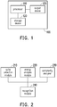
- FIG. 1 is a block diagram of a system for processing an electroencephalogram (EEG) signal according to an embodiment of the disclosure.
- a system for processing an EEG signal 100 is a device for analyzing an EEG signal.
- the system for processing an EEG signal 100 may be a computing device such as a desktop computer, a notebook computer, a smart phone, etc.
- the system for processing an EEG signal 100 includes a processor 110, a storage device 120, and an output device 130.
- the processor 110 is, for example, a central processing unit (CPU), a physics processing unit (PPU), a programmable microprocessor, an embedded control chip, a digital signal processor (DSP), an application specific integrated circuits (ASIC), or other similar devices.
- CPU central processing unit
- PPU physics processing unit
- DSP digital signal processor
- ASIC application specific integrated circuits
- the storage device 120 is, for example, any type of fixed or removable random-access memory (RAM), read-only memory (ROM), flash memory, hard disk, other similar devices, or a combination of the aforementioned devices. Multiple code fragments are stored in the storage device 120. The code fragments are performed by the processor 110 after being installed to implement the method for processing the EEG signal described later.
- the output device 130 is, for example, a display.
- the processor 110 may also store the determination result in the storage device 120 or transmit the determination result to a server of a medical center through a communication device (not shown) via network.
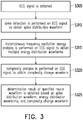
- FIG. 2 is a block diagram of an EEG signal processing module according to an embodiment of the disclosure.
- the EEG signal processing module shown in FIG. 2 is, for example, composed of multiple program code fragments stored in the storage device 120.
- the EEG signal processing module includes a spike detection module 210, an energy analysis module 220, a complexity analyzer 230, and a recognition module 240.
- the spike detection module 210 is configured to perform a spike detection on the EEG signal.
- the energy analysis module 220 is configured to perform an instantaneous frequency oscillation energy analysis on the EEG signal.
- the complexity analyzer 230 is configured to perform a complexity analysis on the EEG signal.
- the recognition module 240 is configured to obtain a time interval of a specified neural waveform based on a spike distribution waveform, energy distribution waveforms, and a complexity change waveform.
- the specified neural waveform is an irregular phase waveform for determining epilepsy onset.
- FIG. 3 is a flowchart of a method for processing an EEG signal according to an embodiment of the disclosure.
- Step S305 the EEG signal is obtained.
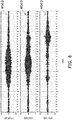
- the EEG signal of a subject is extracted using an EEG measuring instrument, as shown in FIG. 4.
- FIG. 4 is a waveform diagram of an EEG signal according to an embodiment of the disclosure.
- An EEG signal x(t) obtained at this time is a time domain signal.
- the system for processing an EEG signal 100 receives the EEG signal x(t) from the EEG measuring instrument, and the processor 110 analyzes the EEG signal x(t) through the EEG signal processing module (shown in FIG. 2 ).
- the EEG signal processing module analyzes the pre-processed EEG signal x(t) via the spike detection module 210, the energy analysis module 220, and the complexity analyzer 230.
- the pre-processing is, for example, band-pass filtering processing, noise filtering processing, re-sampling processing, time-series segmentation processing, etc.
- the spike detection module 210, the energy analysis module 220, and the complexity analyzer 230 respectively calculate non-stationary waveform characteristics (characteristics of irregular phase) with a preset time-series window. After that, the spike detection module 210, the energy analysis module 220, and the complexity analyzer 230 transmit obtained results to the recognition module 240.
- the recognition module 240 interprets the specified neural waveform and finally outputs a result.
- the non-stationary waveform characteristics include: increased amplitude density (i.e., fewer oscillations, larger amplitude), frequency drift (wider frequency band, dominant frequency drift), larger waveform density spacing (relative to start of onset), and inconsistent spacings (disorder is too large).
- Step S310, Step S315, and Step S320 are used to respectively illustrate the spike detection module 210, the energy analysis module 220, and the complexity analyzer 230.
- the steps may be performed simultaneously or separately, and the sequence of performing the steps is not limited herein.
- Step S310 the spike detection module 210 performs a spike detection on the EEG signal to obtain a spike distribution waveform.
- the spike detection module 210 divides the EEG signal x(t) into multiple sampling intervals using a window width (first window width) to detect a spike number in each sampling interval.
- the spike detection module 210 records the spike number included in each sampling interval following the time series in the spike distribution waveform diagram, thereby obtaining a spike distribution waveform s(x(t)), as shown in FIG. 5.
- FIG. 5 is a spike distribution waveform diagram according to an embodiment of the disclosure.
- the window width is 5 seconds and taking a signal segment from 0 to 5 seconds in the EEG signal x(t), the number of spikes of the signal in 5 seconds is calculated.
- the spike number is projected to the 5 th second of the spike distribution waveform diagram shown in FIG. 5 .
- a spike number is recorded every 5 seconds.
- the time unit of the spike distribution waveform s(x(t)) is the window width (first window width).
- Step S315 the energy analysis module 220 performs an instantaneous frequency oscillation energy analysis on the EEG signal to obtain multiple energy distribution waveforms.
- FIG. 6 is a waveform diagram of an intrinsic mode signal according to an embodiment of the disclosure.
- FIG. 7 is an instantaneous frequency distribution waveform diagram according to an embodiment of the disclosure.
- FIG. 8 is an energy distribution waveform diagram according to an embodiment of the disclosure.
- the energy analysis module 22 decomposes the EEG signal x(t) to be analyzed into multiple intrinsic mode functions (in the embodiment, three intrinsic modes signals M1(x(t)), M2(x(t)), and M3(x(t)) are exemplified for illustration) by performing an empirical mode decomposition (EMD) method.
- EMD empirical mode decomposition
- the energy analysis module 22 calculates an instantaneous frequency of each of the intrinsic mode signals M1(x(t)), M2(x(t)), and M3(x(t)) in each of multiple sampling intervals.
- the intrinsic mode signal M1(x(t)) is divided into multiple sampling intervals using a window width (second window width). Then, the instantaneous frequency of the signal in each sampling interval is calculated, for example, using the Hilbert transform, thereby obtaining an instantaneous frequency distribution waveform f(M1(x(t))) shown in FIG. 7 .
- the intrinsic mode signal M2(x(t)) and the intrinsic mode signal M3(x(t)) are respectively converted into an instantaneous frequency distribution waveform f(M2(x(t))) and an instantaneous frequency distribution waveform f(M3(x(t))). That is, in an instantaneous frequency distribution diagram corresponding to each intrinsic mode signal, the instantaneous frequency corresponding to each sampling interval is recorded following the time series, thereby obtaining the instantaneous frequency distribution waveform corresponding to each intrinsic mode signal.
- the energy analysis module 22 respectively performs energy calculations on the multiple instantaneous frequency distribution waveforms f(M1(x(t))), f(M2(x(t))), and f(M3(x(t))) to obtain multiple energy distribution waveforms E(f(M1(x(t))), E(f(M2(x(t))), and E(f(M3(x(t))), as shown in FIG. 8 .
- the energy calculated by the energy analysis module 22 is spectral energy density or power spectral density.
- Step S320 the complexity analyzer 230 performs a complexity analysis on the EEG signal to obtain a complexity change waveform.
- FIG. 9 is a complexity waveform diagram according to an embodiment of the disclosure.
- FIG. 10 is a complexity spike distribution diagram according to an embodiment of the disclosure.
- the complexity analyzer 230 divides the EEG signal x(t) into multiple sampling intervals using a window width (third window width) to calculate a complexity of each sampling interval.
- the third window width is, for example, 1 second.
- the complexity analyzer 230 calculates an entropy of each sampling interval.
- the complexity analyzer 230 records the complexity (entropy) corresponding to each sampling interval following the time series, thereby obtaining a complexity waveform En(x(t)).
- the entropy is, for example, an approximate entropy (ApEn).
- the approximate entropy is a mathematical method for analyzing the complexity of time-series connotation information. By calculating an entropy value of a signal at different time-space scales, a quantified standard for testing the complexity of the signal is provided. The approximate entropy calculates self-similarity difference of two adjacent time scales in a sampling interval. The higher the complexity, the higher the self-similarity ratio at a difference of one scale.
- the complexity analyzer 230 divides the complexity waveform En(x(t)) into multiple calculation intervals using another window width (fourth window width).
- the complexity analyzer 230 detects the spike number included in each calculation interval, and records the spike number included in each calculation interval following the time series in the complexity spike distribution diagram shown in FIG. 10 , thereby obtaining a complexity change waveform S(En(x(t))).
- the fourth window width is, for example, 7 seconds.
- the complexity analyzer 230 takes a signal segment from 0 to 7 seconds in a complexity waveform En(x(t)), calculates the number of spikes of the signal in 7 seconds, and projects the obtained spike number to the 7 th second of the complexity spike distribution diagram shown in FIG. 10 . By analogy, a spike number is recorded every 7 seconds.
- the time unit of the complexity change waveform S(En(x(t))) is the fourth window width.
- the recognition module 240 obtains a determination result of the specified neural waveform based on the spike distribution waveform s(x(t)), the energy distribution waveforms E(f(M1(x(t)))), E(f(M2(x(t))), and E(f(M3(x(t)))), and the complexity change waveform S(En(x(t))).
- the determination result includes a time interval where the specified neural waveform is located in the EEG signal.
- a waveform in the time interval of the spike distribution waveform s(x(t)) conforms to the spike distribution rule of the specified neural waveform.
- Waveforms in the time intervals of all the energy distribution waveforms E(f(M1(x(t))), E(f(M2(x(t))), and E(f(M3(x(t)))) conform to the energy change rule of the specified neural waveform.
- a waveform in the time interval of the complexity change waveform S(En(x(t))) conforms to the complexity change rule of the specified neural waveform.
- the recognition module 240 determines whether the waveforms conform to the corresponding rule one by one according to a preset unit interval.
- the recognition module 240 determines whether the spike numbers in multiple unit intervals of the spike distribution waveform s(x(t)) conform to the spike distribution rule. In two adjacent unit intervals in the time series, if the spike number in a later unit interval decreases compared with the spike number in an earlier unit interval, the later unit interval is determined as conforming to the spike distribution rule. In this way, the spike detection module 210 determines whether the spike numbers decrease. For example, the waveform in an interval 510 shown in FIG. 5 is determined as conforming to the spike distribution rule.
- the recognition module 240 discriminates whether each unit interval of the spike distribution waveform s(x(t)) conforms to the spike distribution rule. Moreover, the recognition module 240 sets a boolean value corresponding to the unit interval conforming to the spike distribution rule as "true” and sets the boolean value corresponding to the unit interval not conforming to the spike distribution rule as "false".
- the recognition module 240 further determines whether energy densities in multiple unit intervals of the energy distribution waveforms E(f(M1(x(t)))), E(f(M2(x(t)))), and E(f(M3(x(t)))) conform to the energy change rule. In two adjacent unit intervals in the time series of each of the energy distribution waveforms at the same time, if the energy density in a later unit interval decreases compared with the energy density in an earlier unit interval, the later unit interval is determined as conforming to the energy change rule.
- the unit interval is determined as conforming to the energy change rule.
- the waveform in an interval 810 shown in FIG. 8 is determined as conforming to the energy change rule.
- the recognition module 240 sets the boolean value corresponding to the unit interval conforming to the energy change rule as "true” and sets the boolean value corresponding to the unit interval not conforming to the energy change rule as "false".
- the recognition module 240 further determines whether the spike numbers in multiple unit intervals of the complexity change waveform S(En(x(t))) conforms to the complexity change rule.
- the unit interval in which the spike number is greater than a preset value is determined as conforming to the complexity change rule. For example, the spike number of the waveform in an interval 1010 shown in FIG. 10 is greater than the preset value, so the interval 1010 is determined as conforming to the complexity change rule.
- the recognition module 240 sets the boolean value corresponding to the unit interval conforming to the complexity change rule as "true” and sets the boolean value corresponding to the unit interval not conforming to the complexity change rule as "false".
- the recognition module 240 finds the unit intervals corresponding to the boolean values that are all "true” in multiple unit intervals included in each of the spike distribution waveform s(x(t)), the energy distribution waveforms E(f(M1(x(t)))), E(f(M2(x(t)))), and (f(M3(x(t)))), and the complexity change waveform S(En(x(t))), which represents the time interval where the specified neural waveform is located.
- the boolean value corresponding to the unit interval from 100 to 110 seconds of the spike value distribution waveform s(x(t)) is "true”
- the boolean values corresponding to the unit interval from 100 to 110 seconds of all three of the energy distribution waveforms E(f (M1(x(t)))), E(f(M2(x(t)))), and E(f(M3(x(t))) are "true”
- the boolean value corresponding to the unit interval from 100 to 110 seconds of the complexity change waveform S(En(x(t))) is "true”
- the unit interval from 100 to 110 seconds is determined as the time interval where the specified neural waveform is located, that is, the irregular phase.
- the disclosure combines the spike detection, the instantaneous frequency oscillation energy analysis, and the complexity analysis, and uses the discrimination of the spike distribution waveform to find pre-ictal and post-ictal characteristic identification. Also, in terms of the discrimination of the energy distribution waveforms, characteristic identification between the irregular phase and the onset can be distinguished. In addition, in terms of the discrimination of the complexity change waveform, characteristic identification of the irregular phase and the bursting phase can be distinguished. As such, the irregular phase in the EEG signal can be accurately found.
Landscapes
- Health & Medical Sciences (AREA)
- Life Sciences & Earth Sciences (AREA)
- Engineering & Computer Science (AREA)
- Public Health (AREA)
- Medical Informatics (AREA)
- General Health & Medical Sciences (AREA)
- Biomedical Technology (AREA)
- Pathology (AREA)
- Molecular Biology (AREA)
- Animal Behavior & Ethology (AREA)
- Physics & Mathematics (AREA)
- Veterinary Medicine (AREA)
- Heart & Thoracic Surgery (AREA)
- Biophysics (AREA)
- Surgery (AREA)
- Psychiatry (AREA)
- Physiology (AREA)
- Signal Processing (AREA)
- Neurology (AREA)
- Psychology (AREA)
- Computer Vision & Pattern Recognition (AREA)
- Artificial Intelligence (AREA)
- Neurosurgery (AREA)
- Data Mining & Analysis (AREA)
- Databases & Information Systems (AREA)
- Epidemiology (AREA)
- Primary Health Care (AREA)
- Power Engineering (AREA)
- Measurement And Recording Of Electrical Phenomena And Electrical Characteristics Of The Living Body (AREA)
Applications Claiming Priority (1)
| Application Number | Priority Date | Filing Date | Title |
|---|---|---|---|
| US16/903,343 US11602299B2 (en) | 2020-06-16 | 2020-06-16 | Method and system for processing electroencephalogram signal |
Publications (2)
| Publication Number | Publication Date |
|---|---|
| EP3925537A1 true EP3925537A1 (fr) | 2021-12-22 |
| EP3925537B1 EP3925537B1 (fr) | 2023-08-30 |
Family
ID=71833280
Family Applications (1)
| Application Number | Title | Priority Date | Filing Date |
|---|---|---|---|
| EP20187999.6A Active EP3925537B1 (fr) | 2020-06-16 | 2020-07-27 | Procédé et système de traitement de signal d'électroencéphalogramme |
Country Status (6)
| Country | Link |
|---|---|
| US (1) | US11602299B2 (fr) |
| EP (1) | EP3925537B1 (fr) |
| CN (1) | CN113876338B (fr) |
| ES (1) | ES2964841T3 (fr) |
| PT (1) | PT3925537T (fr) |
| TW (1) | TWI743842B (fr) |
Families Citing this family (1)
| Publication number | Priority date | Publication date | Assignee | Title |
|---|---|---|---|---|
| CN118332324B (zh) * | 2024-06-12 | 2024-10-22 | 中国人民解放军海军工程大学 | 一种基于相位与残差信息的共空间模式特征提取方法 |
Citations (3)
| Publication number | Priority date | Publication date | Assignee | Title |
|---|---|---|---|---|
| US20020103512A1 (en) * | 2000-12-12 | 2002-08-01 | Echauz Javier Ramon | Adaptive method and apparatus for forecasting and controlling neurological disturbances under a multi-level control |
| CN108143409A (zh) * | 2016-12-06 | 2018-06-12 | 中国移动通信有限公司研究院 | 睡眠阶段分期方法及装置 |
| EP3656299A1 (fr) * | 2018-11-21 | 2020-05-27 | A-Neuron Electronic Corp. | Procédé et système de détection d'événement neurologique |
Family Cites Families (22)
| Publication number | Priority date | Publication date | Assignee | Title |
|---|---|---|---|---|
| US20110082381A1 (en) * | 2008-06-25 | 2011-04-07 | Basim M Uthman | Time Frequency Transformation Analysis for Detection and Quantification of Epileptiform Activity Load in Generalized Epilepsies |
| TWI398238B (zh) | 2009-11-20 | 2013-06-11 | 慈濟學校財團法人慈濟大學 | Detection and prediction of brainwave emergencies |
| US8280501B2 (en) * | 2010-04-16 | 2012-10-02 | Dyna Dx Corporation | Systems and methods for quantitatively characterizing slow wave activities and states in sleep |
| US10172567B2 (en) | 2011-06-01 | 2019-01-08 | Drexel University | System and method of detecting and predicting seizures |
| US10206591B2 (en) | 2011-10-14 | 2019-02-19 | Flint Hills Scientific, Llc | Seizure detection methods, apparatus, and systems using an autoregression algorithm |
| JP2015047452A (ja) * | 2013-09-04 | 2015-03-16 | 国立大学法人山口大学 | 脳波信号を解析評価する方法、脳波信号解析評価装置及び脳波信号を解析評価するためのプログラム |
| GB201321124D0 (en) | 2013-11-29 | 2014-01-15 | Neuropro Ltd | A monitoring or predicting system and method of monitoring or predicting |
| WO2016039182A1 (fr) | 2014-09-09 | 2016-03-17 | 日本電信電話株式会社 | Procédé de détection des battements du cœur et dispositif de détection des battements du cœur |
| CN104720796B (zh) | 2015-02-12 | 2017-10-20 | 西安交通大学 | 一种用于癫痫发作时间段的自动检测系统及方法 |
| TWI552004B (zh) | 2015-03-12 | 2016-10-01 | 國立交通大學 | 信號分解方法及其電子裝置 |
| CN105147248B (zh) * | 2015-07-30 | 2019-02-05 | 华南理工大学 | 基于生理信息的抑郁症评估系统及其评估方法 |
| TWI538661B (zh) | 2015-08-18 | 2016-06-21 | 國立交通大學 | 即時腦波去除雜訊之方法 |
| TWM567613U (zh) | 2016-01-22 | 2018-10-01 | 神仙科學股份有限公司 | Wearable physiological sensing device and system |
| CA2975184C (fr) | 2016-03-04 | 2018-09-18 | Vera Nenadovic | Systeme, procede et dispositif de surveillance du cerveau en temps reel |
| CN105919590B (zh) * | 2016-06-02 | 2017-03-29 | 浙江铭众科技有限公司 | 一种多通道心电图的qrs自动划定方法 |
| CN107788967B (zh) | 2016-08-30 | 2021-07-06 | 华邦电子股份有限公司 | 疲劳检测装置与疲劳检测方法 |
| TWI605792B (zh) | 2016-10-07 | 2017-11-21 | 中山醫學大學附設醫院 | Abnormal brain location of the brain wave detection system |
| TWI620546B (zh) * | 2017-05-04 | 2018-04-11 | 晶神醫創股份有限公司 | 腦波分析方法及其裝置 |
| JP6680825B2 (ja) * | 2017-08-14 | 2020-04-15 | 裕一 高田 | 脳波の評価方法及び評価装置 |
| US11318278B2 (en) * | 2017-09-13 | 2022-05-03 | Massachusetts Institute Of Technology | Methods and apparatus for inducing or modifying sleep |
| CN109034015B (zh) * | 2018-07-11 | 2022-01-28 | 重庆邮电大学 | Fsk-ssvep的解调系统及解调算法 |
| CN110811609B (zh) * | 2019-10-28 | 2022-11-22 | 杭州电子科技大学 | 基于自适应模板匹配与机器学习算法融合的癫痫棘波智能检测装置 |
-
2020
- 2020-06-16 US US16/903,343 patent/US11602299B2/en active Active
- 2020-06-18 TW TW109120543A patent/TWI743842B/zh active
- 2020-07-10 CN CN202010660934.3A patent/CN113876338B/zh active Active
- 2020-07-27 PT PT201879996T patent/PT3925537T/pt unknown
- 2020-07-27 EP EP20187999.6A patent/EP3925537B1/fr active Active
- 2020-07-27 ES ES20187999T patent/ES2964841T3/es active Active
Patent Citations (3)
| Publication number | Priority date | Publication date | Assignee | Title |
|---|---|---|---|---|
| US20020103512A1 (en) * | 2000-12-12 | 2002-08-01 | Echauz Javier Ramon | Adaptive method and apparatus for forecasting and controlling neurological disturbances under a multi-level control |
| CN108143409A (zh) * | 2016-12-06 | 2018-06-12 | 中国移动通信有限公司研究院 | 睡眠阶段分期方法及装置 |
| EP3656299A1 (fr) * | 2018-11-21 | 2020-05-27 | A-Neuron Electronic Corp. | Procédé et système de détection d'événement neurologique |
Also Published As
| Publication number | Publication date |
|---|---|
| PT3925537T (pt) | 2023-10-03 |
| US11602299B2 (en) | 2023-03-14 |
| TWI743842B (zh) | 2021-10-21 |
| EP3925537B1 (fr) | 2023-08-30 |
| CN113876338B (zh) | 2025-02-11 |
| ES2964841T3 (es) | 2024-04-09 |
| TW202200076A (zh) | 2022-01-01 |
| CN113876338A (zh) | 2022-01-04 |
| US20210386311A1 (en) | 2021-12-16 |
Similar Documents
| Publication | Publication Date | Title |
|---|---|---|
| Liu et al. | Epileptic seizure detection and prediction in EEGs using power spectra density parameterization | |
| Subha et al. | EEG signal analysis: a survey | |
| Borowska | Entropy-based algorithms in the analysis of biomedical signals | |
| Sharanreddy et al. | EEG signal classification for epilepsy seizure detection using improved approximate entropy | |
| Boashash et al. | Time-frequency processing of nonstationary signals: Advanced TFD design to aid diagnosis with highlights from medical applications | |
| US7299088B1 (en) | Apparatus and methods for brain rhythm analysis | |
| Harrison et al. | Correlation dimension and integral do not predict epileptic seizures | |
| CN104720796B (zh) | 一种用于癫痫发作时间段的自动检测系统及方法 | |
| Martis et al. | Epileptic EEG classification using nonlinear parameters on different frequency bands | |
| JP2022536552A (ja) | 脳波(eeg)の非線形性の変化に基づく発作検出システム及び方法 | |
| JP7562745B2 (ja) | 脳波(eeg)の非線形性の変化に基づく発作検出システム及び方法 | |
| CN102397069A (zh) | 用于自动癫痫监测的方法、设备和计算机程序产品 | |
| CN115486814A (zh) | 基于多模态癫痫数据智能融合分析与处理方法 | |
| US10702175B2 (en) | Brain activity analysis method and apparatus thereof | |
| KR102256313B1 (ko) | 뇌전도 신호 기반 멀티 주파수 대역 계수를 이용한 특징추출 및 확률모델과 기계학습에 의한 간질 발작파 자동 검출 방법 및 장치 | |
| Wang et al. | Eeg-based real-time drowsiness detection using hilbert-huang transform | |
| Zhao et al. | Identification of epileptic seizures by characterizing instantaneous energy behavior of EEG | |
| Nagarajan et al. | Scalable machine learning architecture for neonatal seizure detection on ultra-edge devices | |
| EP3925537B1 (fr) | Procédé et système de traitement de signal d'électroencéphalogramme | |
| US10512434B2 (en) | Brain activity measurement device, program, and method | |
| Poetto et al. | Classification of schizophrenia eeg recording using homological features | |
| Aydin | Determination of autoregressive model orders for seizure detection | |
| Kannathal et al. | Complex dynamics of epileptic EEG | |
| RU2751137C1 (ru) | Способ определения фазы сна в длительной записи ээг | |
| KR20210076379A (ko) | 웨이블릿 변환을 이용한 자궁근전도 신호 분석 기반 조산 위험 모니터링 방법 및 시스템 |
Legal Events
| Date | Code | Title | Description |
|---|---|---|---|
| PUAI | Public reference made under article 153(3) epc to a published international application that has entered the european phase |
Free format text: ORIGINAL CODE: 0009012 |
|
| STAA | Information on the status of an ep patent application or granted ep patent |
Free format text: STATUS: REQUEST FOR EXAMINATION WAS MADE |
|
| 17P | Request for examination filed |
Effective date: 20200727 |
|
| AK | Designated contracting states |
Kind code of ref document: A1 Designated state(s): AL AT BE BG CH CY CZ DE DK EE ES FI FR GB GR HR HU IE IS IT LI LT LU LV MC MK MT NL NO PL PT RO RS SE SI SK SM TR |
|
| B565 | Issuance of search results under rule 164(2) epc |
Effective date: 20210119 |
|
| RBV | Designated contracting states (corrected) |
Designated state(s): AL AT BE BG CH CY CZ DE DK EE ES FI FR GB GR HR HU IE IS IT LI LT LU LV MC MK MT NL NO PL PT RO RS SE SI SK SM TR |
|
| GRAP | Despatch of communication of intention to grant a patent |
Free format text: ORIGINAL CODE: EPIDOSNIGR1 |
|
| STAA | Information on the status of an ep patent application or granted ep patent |
Free format text: STATUS: GRANT OF PATENT IS INTENDED |
|
| INTG | Intention to grant announced |
Effective date: 20230315 |
|
| GRAS | Grant fee paid |
Free format text: ORIGINAL CODE: EPIDOSNIGR3 |
|
| P01 | Opt-out of the competence of the unified patent court (upc) registered |
Effective date: 20230528 |
|
| GRAA | (expected) grant |
Free format text: ORIGINAL CODE: 0009210 |
|
| STAA | Information on the status of an ep patent application or granted ep patent |
Free format text: STATUS: THE PATENT HAS BEEN GRANTED |
|
| AK | Designated contracting states |
Kind code of ref document: B1 Designated state(s): AL AT BE BG CH CY CZ DE DK EE ES FI FR GB GR HR HU IE IS IT LI LT LU LV MC MK MT NL NO PL PT RO RS SE SI SK SM TR |
|
| REG | Reference to a national code |
Ref country code: GB Ref legal event code: FG4D |
|
| REG | Reference to a national code |
Ref country code: CH Ref legal event code: EP |
|
| REG | Reference to a national code |
Ref country code: DE Ref legal event code: R096 Ref document number: 602020016563 Country of ref document: DE |
|
| REG | Reference to a national code |
Ref country code: IE Ref legal event code: FG4D |
|
| REG | Reference to a national code |
Ref country code: PT Ref legal event code: SC4A Ref document number: 3925537 Country of ref document: PT Date of ref document: 20231003 Kind code of ref document: T Free format text: AVAILABILITY OF NATIONAL TRANSLATION Effective date: 20230927 |
|
| REG | Reference to a national code |
Ref country code: NL Ref legal event code: FP |
|
| REG | Reference to a national code |
Ref country code: SE Ref legal event code: TRGR |
|
| REG | Reference to a national code |
Ref country code: LT Ref legal event code: MG9D |
|
| PG25 | Lapsed in a contracting state [announced via postgrant information from national office to epo] |
Ref country code: GR Free format text: LAPSE BECAUSE OF FAILURE TO SUBMIT A TRANSLATION OF THE DESCRIPTION OR TO PAY THE FEE WITHIN THE PRESCRIBED TIME-LIMIT Effective date: 20231201 |
|
| PG25 | Lapsed in a contracting state [announced via postgrant information from national office to epo] |
Ref country code: IS Free format text: LAPSE BECAUSE OF FAILURE TO SUBMIT A TRANSLATION OF THE DESCRIPTION OR TO PAY THE FEE WITHIN THE PRESCRIBED TIME-LIMIT Effective date: 20231230 |
|
| PG25 | Lapsed in a contracting state [announced via postgrant information from national office to epo] |
Ref country code: RS Free format text: LAPSE BECAUSE OF FAILURE TO SUBMIT A TRANSLATION OF THE DESCRIPTION OR TO PAY THE FEE WITHIN THE PRESCRIBED TIME-LIMIT Effective date: 20230830 Ref country code: NO Free format text: LAPSE BECAUSE OF FAILURE TO SUBMIT A TRANSLATION OF THE DESCRIPTION OR TO PAY THE FEE WITHIN THE PRESCRIBED TIME-LIMIT Effective date: 20231130 Ref country code: LV Free format text: LAPSE BECAUSE OF FAILURE TO SUBMIT A TRANSLATION OF THE DESCRIPTION OR TO PAY THE FEE WITHIN THE PRESCRIBED TIME-LIMIT Effective date: 20230830 Ref country code: LT Free format text: LAPSE BECAUSE OF FAILURE TO SUBMIT A TRANSLATION OF THE DESCRIPTION OR TO PAY THE FEE WITHIN THE PRESCRIBED TIME-LIMIT Effective date: 20230830 Ref country code: IS Free format text: LAPSE BECAUSE OF FAILURE TO SUBMIT A TRANSLATION OF THE DESCRIPTION OR TO PAY THE FEE WITHIN THE PRESCRIBED TIME-LIMIT Effective date: 20231230 Ref country code: HR Free format text: LAPSE BECAUSE OF FAILURE TO SUBMIT A TRANSLATION OF THE DESCRIPTION OR TO PAY THE FEE WITHIN THE PRESCRIBED TIME-LIMIT Effective date: 20230830 Ref country code: GR Free format text: LAPSE BECAUSE OF FAILURE TO SUBMIT A TRANSLATION OF THE DESCRIPTION OR TO PAY THE FEE WITHIN THE PRESCRIBED TIME-LIMIT Effective date: 20231201 Ref country code: FI Free format text: LAPSE BECAUSE OF FAILURE TO SUBMIT A TRANSLATION OF THE DESCRIPTION OR TO PAY THE FEE WITHIN THE PRESCRIBED TIME-LIMIT Effective date: 20230830 |
|
| PG25 | Lapsed in a contracting state [announced via postgrant information from national office to epo] |
Ref country code: PL Free format text: LAPSE BECAUSE OF FAILURE TO SUBMIT A TRANSLATION OF THE DESCRIPTION OR TO PAY THE FEE WITHIN THE PRESCRIBED TIME-LIMIT Effective date: 20230830 |
|
| REG | Reference to a national code |
Ref country code: ES Ref legal event code: FG2A Ref document number: 2964841 Country of ref document: ES Kind code of ref document: T3 Effective date: 20240409 |
|
| PG25 | Lapsed in a contracting state [announced via postgrant information from national office to epo] |
Ref country code: SM Free format text: LAPSE BECAUSE OF FAILURE TO SUBMIT A TRANSLATION OF THE DESCRIPTION OR TO PAY THE FEE WITHIN THE PRESCRIBED TIME-LIMIT Effective date: 20230830 Ref country code: RO Free format text: LAPSE BECAUSE OF FAILURE TO SUBMIT A TRANSLATION OF THE DESCRIPTION OR TO PAY THE FEE WITHIN THE PRESCRIBED TIME-LIMIT Effective date: 20230830 Ref country code: EE Free format text: LAPSE BECAUSE OF FAILURE TO SUBMIT A TRANSLATION OF THE DESCRIPTION OR TO PAY THE FEE WITHIN THE PRESCRIBED TIME-LIMIT Effective date: 20230830 Ref country code: DK Free format text: LAPSE BECAUSE OF FAILURE TO SUBMIT A TRANSLATION OF THE DESCRIPTION OR TO PAY THE FEE WITHIN THE PRESCRIBED TIME-LIMIT Effective date: 20230830 Ref country code: CZ Free format text: LAPSE BECAUSE OF FAILURE TO SUBMIT A TRANSLATION OF THE DESCRIPTION OR TO PAY THE FEE WITHIN THE PRESCRIBED TIME-LIMIT Effective date: 20230830 Ref country code: SK Free format text: LAPSE BECAUSE OF FAILURE TO SUBMIT A TRANSLATION OF THE DESCRIPTION OR TO PAY THE FEE WITHIN THE PRESCRIBED TIME-LIMIT Effective date: 20230830 |
|
| REG | Reference to a national code |
Ref country code: DE Ref legal event code: R097 Ref document number: 602020016563 Country of ref document: DE |
|
| PLBE | No opposition filed within time limit |
Free format text: ORIGINAL CODE: 0009261 |
|
| STAA | Information on the status of an ep patent application or granted ep patent |
Free format text: STATUS: NO OPPOSITION FILED WITHIN TIME LIMIT |
|
| PG25 | Lapsed in a contracting state [announced via postgrant information from national office to epo] |
Ref country code: SI Free format text: LAPSE BECAUSE OF FAILURE TO SUBMIT A TRANSLATION OF THE DESCRIPTION OR TO PAY THE FEE WITHIN THE PRESCRIBED TIME-LIMIT Effective date: 20230830 |
|
| 26N | No opposition filed |
Effective date: 20240603 |
|
| PG25 | Lapsed in a contracting state [announced via postgrant information from national office to epo] |
Ref country code: BG Free format text: LAPSE BECAUSE OF FAILURE TO SUBMIT A TRANSLATION OF THE DESCRIPTION OR TO PAY THE FEE WITHIN THE PRESCRIBED TIME-LIMIT Effective date: 20230830 |
|
| PG25 | Lapsed in a contracting state [announced via postgrant information from national office to epo] |
Ref country code: BG Free format text: LAPSE BECAUSE OF FAILURE TO SUBMIT A TRANSLATION OF THE DESCRIPTION OR TO PAY THE FEE WITHIN THE PRESCRIBED TIME-LIMIT Effective date: 20230830 |
|
| REG | Reference to a national code |
Ref country code: AT Ref legal event code: UEP Ref document number: 1604340 Country of ref document: AT Kind code of ref document: T Effective date: 20230830 |
|
| PG25 | Lapsed in a contracting state [announced via postgrant information from national office to epo] |
Ref country code: MC Free format text: LAPSE BECAUSE OF FAILURE TO SUBMIT A TRANSLATION OF THE DESCRIPTION OR TO PAY THE FEE WITHIN THE PRESCRIBED TIME-LIMIT Effective date: 20230830 |
|
| PG25 | Lapsed in a contracting state [announced via postgrant information from national office to epo] |
Ref country code: LU Free format text: LAPSE BECAUSE OF NON-PAYMENT OF DUE FEES Effective date: 20240727 |
|
| PG25 | Lapsed in a contracting state [announced via postgrant information from national office to epo] |
Ref country code: LU Free format text: LAPSE BECAUSE OF NON-PAYMENT OF DUE FEES Effective date: 20240727 |
|
| PGFP | Annual fee paid to national office [announced via postgrant information from national office to epo] |
Ref country code: IE Payment date: 20250624 Year of fee payment: 6 |
|
| PGFP | Annual fee paid to national office [announced via postgrant information from national office to epo] |
Ref country code: SE Payment date: 20250630 Year of fee payment: 6 |
|
| PGFP | Annual fee paid to national office [announced via postgrant information from national office to epo] |
Ref country code: NL Payment date: 20250710 Year of fee payment: 6 |
|
| PGFP | Annual fee paid to national office [announced via postgrant information from national office to epo] |
Ref country code: ES Payment date: 20250801 Year of fee payment: 6 Ref country code: PT Payment date: 20250721 Year of fee payment: 6 |
|
| PGFP | Annual fee paid to national office [announced via postgrant information from national office to epo] |
Ref country code: DE Payment date: 20250730 Year of fee payment: 6 |
|
| PGFP | Annual fee paid to national office [announced via postgrant information from national office to epo] |
Ref country code: IT Payment date: 20250721 Year of fee payment: 6 |
|
| PGFP | Annual fee paid to national office [announced via postgrant information from national office to epo] |
Ref country code: BE Payment date: 20250728 Year of fee payment: 6 Ref country code: GB Payment date: 20250722 Year of fee payment: 6 |
|
| PGFP | Annual fee paid to national office [announced via postgrant information from national office to epo] |
Ref country code: AT Payment date: 20250725 Year of fee payment: 6 Ref country code: FR Payment date: 20250722 Year of fee payment: 6 |
|
| PGFP | Annual fee paid to national office [announced via postgrant information from national office to epo] |
Ref country code: CH Payment date: 20250801 Year of fee payment: 6 |
|
| PG25 | Lapsed in a contracting state [announced via postgrant information from national office to epo] |
Ref country code: CY Free format text: LAPSE BECAUSE OF FAILURE TO SUBMIT A TRANSLATION OF THE DESCRIPTION OR TO PAY THE FEE WITHIN THE PRESCRIBED TIME-LIMIT; INVALID AB INITIO Effective date: 20200727 |
|
| PG25 | Lapsed in a contracting state [announced via postgrant information from national office to epo] |
Ref country code: HU Free format text: LAPSE BECAUSE OF FAILURE TO SUBMIT A TRANSLATION OF THE DESCRIPTION OR TO PAY THE FEE WITHIN THE PRESCRIBED TIME-LIMIT; INVALID AB INITIO Effective date: 20200727 |