EP3925742B1 - Procédé, dispositif et traceur laser pour traiter des pièces - Google Patents
Procédé, dispositif et traceur laser pour traiter des pièces Download PDFInfo
- Publication number
- EP3925742B1 EP3925742B1 EP20212630.6A EP20212630A EP3925742B1 EP 3925742 B1 EP3925742 B1 EP 3925742B1 EP 20212630 A EP20212630 A EP 20212630A EP 3925742 B1 EP3925742 B1 EP 3925742B1
- Authority
- EP
- European Patent Office
- Prior art keywords
- graphic
- workpiece
- area
- processing
- laser
- Prior art date
- Legal status (The legal status is an assumption and is not a legal conclusion. Google has not performed a legal analysis and makes no representation as to the accuracy of the status listed.)
- Active
Links
Images




Classifications
-
- B—PERFORMING OPERATIONS; TRANSPORTING
- B23—MACHINE TOOLS; METAL-WORKING NOT OTHERWISE PROVIDED FOR
- B23K—SOLDERING OR UNSOLDERING; WELDING; CLADDING OR PLATING BY SOLDERING OR WELDING; CUTTING BY APPLYING HEAT LOCALLY, e.g. FLAME CUTTING; WORKING BY LASER BEAM
- B23K26/00—Working by laser beam, e.g. welding, cutting or boring
- B23K26/36—Removing material
-
- B—PERFORMING OPERATIONS; TRANSPORTING
- B23—MACHINE TOOLS; METAL-WORKING NOT OTHERWISE PROVIDED FOR
- B23K—SOLDERING OR UNSOLDERING; WELDING; CLADDING OR PLATING BY SOLDERING OR WELDING; CUTTING BY APPLYING HEAT LOCALLY, e.g. FLAME CUTTING; WORKING BY LASER BEAM
- B23K26/00—Working by laser beam, e.g. welding, cutting or boring
- B23K26/36—Removing material
- B23K26/38—Removing material by boring or cutting
-
- B—PERFORMING OPERATIONS; TRANSPORTING
- B23—MACHINE TOOLS; METAL-WORKING NOT OTHERWISE PROVIDED FOR
- B23K—SOLDERING OR UNSOLDERING; WELDING; CLADDING OR PLATING BY SOLDERING OR WELDING; CUTTING BY APPLYING HEAT LOCALLY, e.g. FLAME CUTTING; WORKING BY LASER BEAM
- B23K26/00—Working by laser beam, e.g. welding, cutting or boring
- B23K26/02—Positioning or observing the workpiece, e.g. with respect to the point of impact; Aligning, aiming or focusing the laser beam
-
- B—PERFORMING OPERATIONS; TRANSPORTING
- B26—HAND CUTTING TOOLS; CUTTING; SEVERING
- B26D—CUTTING; DETAILS COMMON TO MACHINES FOR PERFORATING, PUNCHING, CUTTING-OUT, STAMPING-OUT OR SEVERING
- B26D5/00—Arrangements for operating and controlling machines or devices for cutting, cutting-out, stamping-out, punching, perforating, or severing by means other than cutting
- B26D5/005—Computer numerical control means
-
- B—PERFORMING OPERATIONS; TRANSPORTING
- B26—HAND CUTTING TOOLS; CUTTING; SEVERING
- B26D—CUTTING; DETAILS COMMON TO MACHINES FOR PERFORATING, PUNCHING, CUTTING-OUT, STAMPING-OUT OR SEVERING
- B26D5/00—Arrangements for operating and controlling machines or devices for cutting, cutting-out, stamping-out, punching, perforating, or severing by means other than cutting
- B26D5/007—Control means comprising cameras, vision or image processing systems
-
- B—PERFORMING OPERATIONS; TRANSPORTING
- B26—HAND CUTTING TOOLS; CUTTING; SEVERING
- B26F—PERFORATING; PUNCHING; CUTTING-OUT; STAMPING-OUT; SEVERING BY MEANS OTHER THAN CUTTING
- B26F1/00—Perforating; Punching; Cutting-out; Stamping-out; Apparatus therefor
- B26F1/38—Cutting-out; Stamping-out
- B26F1/3806—Cutting-out; Stamping-out wherein relative movements of tool head and work during cutting have a component tangential to the work surface
- B26F1/3813—Cutting-out; Stamping-out wherein relative movements of tool head and work during cutting have a component tangential to the work surface wherein the tool head is moved in a plane parallel to the work in a coordinate system fixed with respect to the work
-
- B—PERFORMING OPERATIONS; TRANSPORTING
- B41—PRINTING; LINING MACHINES; TYPEWRITERS; STAMPS
- B41M—PRINTING, DUPLICATING, MARKING, OR COPYING PROCESSES; COLOUR PRINTING
- B41M5/00—Duplicating or marking methods; Sheet materials for use therein
- B41M5/26—Thermography ; Marking by high energetic means, e.g. laser otherwise than by burning, and characterised by the material used
-
- B—PERFORMING OPERATIONS; TRANSPORTING
- B26—HAND CUTTING TOOLS; CUTTING; SEVERING
- B26D—CUTTING; DETAILS COMMON TO MACHINES FOR PERFORATING, PUNCHING, CUTTING-OUT, STAMPING-OUT OR SEVERING
- B26D5/00—Arrangements for operating and controlling machines or devices for cutting, cutting-out, stamping-out, punching, perforating, or severing by means other than cutting
- B26D2005/002—Performing a pattern matching operation
Definitions
- the invention relates to a method for machining workpieces as described in the preamble of claim 1.
- the workpiece in particular the register marks, are detected in order to determine the position and alignment of the workpiece, in particular the applied graphic or graphic area, in the processing area of the laser plotter, whereupon the processing process for cutting out the graphic is carried out.
- the object of the invention is to create a method in which the handling, in particular the positioning of the workpiece, is significantly improved.
- a further object is to eliminate the disadvantages of the prior art as far as possible.
- the object of the invention is achieved by a method such that after the processing process the actual recognized position of the recognition features and/or the corresponding graphic or graphic area is displayed at the corresponding position in the workspace on the computer.
- the advantage here is that the user is immediately given the opportunity to improve the recognition for the next processing process.
- a measure in which a message for correcting the new position of the graphic or graphic area is displayed on the display elements and/or on the laser plotter, so that upon confirmation the new position is corrected for the next processing process, advantageously ensures that a job is only repositioned at the explicit request of the user, and thus a one-time inaccurately inserted material has no negative effect on subsequent processing processes.
- Another advantage is the measure whereby, in the case of a manual correction during the processing process on the laser plotter, the position defined on the display element in the work area is compared with the actual position in the processing area of the laser plotter in order to detect the first identification feature, since this means that a comparison is only carried out in the case of a manual correction, so that an immediate start with a new processing process is possible if no correction is made.
- a processing device 1 in particular a laser plotter 2, or also called a laser engraver, is shown schematically, in which at least one, in particular two radiation sources 4 in the form of lasers 5, 6 are arranged and operated in a housing 3.
- the lasers 5 and 6 preferably act alternately on the workpiece 7 to be processed, the workpiece 7 being in a processing area 8 of the laser plotter 2, in particular on a processing table 9.
- a laser beam 10 emitted by the radiation source 4 is sent via deflection elements 11 to at least one movable focusing unit 12 designed for both radiation sources 4, from which the laser beam 10 is deflected in the direction of the workpiece 7 and focused for processing.
- the control in particular the position control of the laser beam 10 to the workpiece 7 is carried out via software running in a control unit 13, wherein a processing job 16 with a graphic 17 and/or a text 18 is created and/or loaded on an external component 14, in particular on a display element 15 in the form of a computer 15 or a control device, which is transferred to the control unit 13 of the laser plotter 2 via a data connection 19, which converts the transferred data, in particular the processing job 16 with the graphic 17 and/or the text 18, from a stored database 20 to control the individual elements of the laser plotter 2.
- the laser plotter 2 also has input means 21, in particular direction keys 22 for moving and positioning the focus unit 12 and thus the laser beam 10. It is possible that additional input keys 21 are present, for example in the form of a confirmation key 23 or the like. It is also possible that a display monitor 24 is present on the processing device 1, on which, for example, the same functions and displays are shown in accordance with the display elements 15. This display monitor 24 can be designed as a touch monitor 24, so that the user can control or enter inputs by touch or does so via the input means 21.
- One or more identical or different processing jobs 16 (as shown schematically) with the graphic 17 or a graphic area and associated identification features 28 can be loaded or can be created by the user, wherein the graphic 17 or the graphic area with the identification features 28 are designed to be movable on the work area 25 shown, so that the graphic 17 or the graphic area can be adapted to the laser position 26 or the laser position 26 can be adapted to the graphic 17 or the graphic area.
- the user can make a corresponding adjustment on the laser plotter 2 using the input means 21 or adjust the focusing unit 12 using an adjustment and/or control area 29 on the display element 15 or by simply moving the laser position 26 with a mouse or pointer on the computer 15.
- means for positioning the workpiece 7, in particular positioning rails, are arranged in the processing area 8 of the laser plotter 2, so that the user can place the workpiece 7 on these means when inserting the workpiece 7 and thus the workpiece 7 is always placed in approximately the same position in the processing area 8.
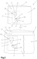
- FIG. 2 to 4 A sequence for handling the laser plotter 2 for carrying out a processing process is now described schematically, in which a partial section of the computer 15, in particular of the work area 25 displayed therein, and a partial section of the laser plotter 2, in particular of the processing area 8, are shown in a simplified and schematic manner so that the sequence of the method becomes clear.
- the user first creates a processing job 16 or loads an already created processing job 16.
- the processing job 16 contains a graphic 17 or a graphic area and identification features 28, which are displayed or represented or created on the external component 14, in particular the computer 15, on the work area 25, as shown in Fig.2 is shown in the work area 25.
- the identification features 28 and the graphic 17 or the graphic area are then applied to the workpiece 7, for example by printing on the workpiece 7
- the workpiece 7 is arranged in the processing area 8 of the laser plotter 2 with an optical unit 30 for detecting the recognition features 28 (see Fig.2 Processing table 9), whereby appropriate aids such as stop rails 34a or the like can be used as means for positioning.
- the workpiece 7, in particular the identification features 28 is detected in order to determine the position and orientation of the workpiece 7, in particular the applied graphic 17 or the graphic area, in the processing area 8, i.e. an automatic position determination of the workpiece 7 is carried out.
- the processing process is carried out, whereby the graphic 17 is preferably cut out by the laser 5 or 6, as is known from the prior art.
- the laser pointer 27 of the laser 5,6 which is arranged on the focus unit 12 and is always present for safety reasons, is positioned on any identification feature 28, ie the user simply moves the laser pointer 27 via the input means 21, in particular the direction keys 22, in such a way that it is aligned on any identification feature 28 selected by the user or shines on it, as shown in Fig. 3 is visible.
- the user then moves the processing image of the graphic 17 or the graphic area with the associated identification feature 28 on the display element 15 shown on the display element 15 in such a way that the laser position 26 shown on the display element 15 now corresponds to the identification feature 28 marked with the laser pointer 27. as in Fig. 4 is visible.
- the position on the display element 15 and on the laser plotter 2 can be coordinated so that when a machining process starts, the correct data, in particular the positions for the laser beam 10, can be determined and transmitted so that the corresponding stored functions can be loaded and generated at the corresponding positions, as is known from the prior art for such machining processes.
- corresponding recognition features 28 are present, which are recognized by the laser plotter 2, in particular by an optical unit 30.
- the optical unit 30 is preferably formed from a camera that records a certain area of the processing table 9, whereby corresponding setting options, such as the contrast, the brightness, the image size, etc., can be made on the computer 15.
- the recognition features 28 are preferably represented by register marks 31, as shown with circles, and/or graphic elements 32, as shown by a dashed circle in Fig.
- the optical unit 30 can record the recognition feature 28 and at the same time check whether the settings for recognition and evaluation are working, ie that after positioning the optical unit 30 records the recognition feature 28 and a recognition is carried out to determine whether smooth recognition is possible.
- an adjustment path is stored between the laser pointer 27 and the optical unit 30, in particular a center of the optical unit 30, so that when the focusing unit 12, on which the optical unit 30 and the laser pointer 27 are arranged, is replaced, it can be adapted accordingly to the new focusing unit 12.
- other required parameters can also be stored and changed.
- the laser plotter 2 moves the optical unit 30 to the predetermined position in such a way that the identification feature 28 is within a definable search window 34, dashed in Fig. 4 shown, is arranged in the optical unit 30.
- a definable search window 34 dashed in Fig. 4 shown, is arranged in the optical unit 30.
- the identification feature 28 it is not absolutely necessary for the identification feature 28 to be arranged in the center, but it only has to be present at least partially, but preferably completely, in the search window 34 so that it is recognized as an identification feature 28.
- the optical unit 30 and the laser 5, 6 or laser beam 10 coupled to it are adjusted such that the identification feature 28 is positioned in the center of the search window 34 or that when the identification feature 28 is recognized within the search window 34, the position of the identification feature 28 relative to the center of the search window 34 or to a starting position or defined point assigned to the search window 34 is calculated. If a shift to the center of the search window 34 is made, it is possible for a defined number of centering attempts to center the recognition feature 28 to be stored in the search window 34, whereby the processing process is then stopped and can be continued manually, i.e.
- the number of attempts is limited, so that with difficult-to-recognize recognition features 28 there is no possibility of the laser plotter 2 trying forever to center it. The user can therefore intervene in the processing process much more quickly.
- a recognition feature 28 is not recognized, by operating an input device 21 on the laser plotter 2 or by activating a button on the display element 15, the unrecognized recognition feature 28 is skipped and the search process is continued with the next defined recognition feature 28 or the corresponding recognition feature 28 is manually set on the laser plotter 2 by controlling it via the input devices 21, whereupon the processing process is continued.
- an error correction of the laser position on the laser plotter 2 is carried out by actuating input means 21, wherein the relative position of the laser position 26 to the graphic 17 or to the graphic area and/or the recognition feature 28 is displayed on the display element 15, ie that, for example, during the first search process the first recognition feature 28 is not recognized, so that the user can manually move to the first position, which is also displayed on the display element 15.
- the closing of the protective cover 35 is detected by a detection means 36, in particular a sensor contact, whereby for safety reasons the laser 5, 6 may not be operated without closing the protective cover 35.
- a detection means 36 in particular a sensor contact
- the laser 5, 6 may not be operated without closing the protective cover 35.
- a new processing process is started on the laser plotter 2 by activating an input means 21, in particular the confirmation means 23, so that the user no longer has to start a new processing process on the computer 15, as is known from the prior art, but can start directly on the laser plotter 2. It is of course possible that an independent input means 21 can be arranged and used for this purpose.
- the processing process is stopped if the first identification feature 28 is not recognized, which can happen, for example, if the workpiece 7 is placed in the wrong position.
- the user can then perform a positioning by manually adjusting using the direction keys 22 and continue the processing process by pressing the confirmation key 23. If the processing process is then interrupted again, the user again has the option of continuing the processing process by taking appropriate corrective measures.
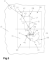
- FIG. 5 A schematic representation of the process for determining the sequence of the identification features 28 to be queried or found one after the other is now shown, whereby only a partial section of the display element 15 with the loaded processing job 16 is shown.
- the graphic 17 or the graphic area is divided into several sectors 37, 38, 39, 40, in particular into four sectors 37, 38, 39, 40, whereby a center point 40a or center or an optimal sector point of the graphic 17 or the graphic area is first determined and determined.
- the division into sectors 37, 38, 39, 40 is shown by dotted lines in Fig. 5 shown schematically.
- the order of the identification features 28 to be queried is now determined, whereby the first identification feature 28 to be queried is a first identification feature 28 in the first sector 37. and is determined, ie that preferably as the first sector 37, 38, 39, 40 that sector 37 is determined which has the shortest adjustment path of the focus unit 12 from a starting point or a parking position 41, which is in the form of a circle in Fig. 5 is shown, and in this sector 37 the first identification feature 28, in particular a first register mark 42, with the shortest travel path 43 from the parking position 41 is determined and defined.
- a second identification feature 28 to be queried in particular a second register mark 44, is determined and defined in a further sector 37, 38, 39, 40, in particular in the diagonal sector 40, wherein preferably the shortest adjustment path 45 from the previously determined first register mark 42 to the closest identification feature 28 in the next sector 40 is determined.
- the closest identification feature 28 can be determined starting from the parking position 41.
- the further identification features 28 are then determined and determined in succession, preferably always those identification features 28 with the shortest adjustment path 46 of the laser 5, 6 or the focus unit 12, i.e. the closest register mark 31 or the closest identification feature 28 is always determined and the order for querying all identification features 28 is thus determined.
- the order can be saved for the corresponding processing job 16, so that such an analysis process is only carried out once when the processing job 16 is created.
- the laser plotter 2 first moves to the first recognition feature 28, i.e. in this embodiment the first register mark 42, and records it with the optical unit 30 and analyses it accordingly.
- the image recorded by the optical unit 30 is stored for the corresponding register mark 42 in the processing job 16, so that the user can query this image during or after the processing process by simply moving to or clicking on the register mark 42, whereupon a new window with the saved image preferably appears.
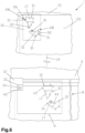
- FIG. 6 and 7 A further development to improve handling for the user is shown. Often the format of the workpiece 7 or the scaling of the graphic 17 changes, so that appropriate adjustments must be made if the position of the graphic 17 shifts as a result.
- workpiece 7 is initially processed as A4 format, so that the user can make a corresponding setting during commissioning, as in the Fig. 1 to 5
- the format of the workpiece 7 changes during the course of the work, for example from A4 to A3
- the position of the graphic 17 on the workpiece 7 often changes, as shown in Fig. 6 in the processing area 8 of the laser plotter 2.
- the focus unit 12 moves, in particular with the search window 34 of the optical unit 30, to the first position, i.e. the first register mark 42, where it was located during the previous machining process.
- This first register mark 42 is shown in dashed lines in order to recognize the previous position.
- the focus unit 12, in particular the optical unit 30, cannot now find a register mark 42 due to the change in the graphic position due to the change in the workpiece format, whereupon the machining process is stopped.
- the original position of the workpiece 7 in A4 format is still displayed.
- the first identification feature 28, in particular the first register mark 42 is not recognized and the processing process is automatically stopped, as in Fig. 6 visible.
- the user can now use the direction keys 22 on the laser plotter 2 to adjust the focusing unit 12 in such a way that the search window 34 of the optical unit 30 or the laser pointer 27 is positioned over the first recognition feature 28, in particular the first register mark 42 of the new position, and this can thus be recognized, whereupon the processing process is continued.
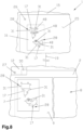
- Fig. 8 a processing process or a method for engraving, marking, labeling and/or cutting workpieces with applied graphics, in particular a graphic area, with the laser plotter 2 is shown, wherein the previously described sequences or methods are also used for engraving or labeling.
- the processing job 16 is first created and/or loaded with a graphic 17 or a graphic area and identification features 28 on the display element 15, in particular the computer 15.
- the workpiece 7 must be produced, i.e. the identification features 28 and the graphic 17 or the graphic area on the workpiece 7 are applied to a base body or blank, in particular this is done by printing the processing job 16 onto the workpiece 7.
- the workpiece 7 is then placed in the processing area 8 of the laser plotter 2 with the optical unit 30 for detecting the identification features 28.
- the workpiece 7, in particular the identification features 28, is recorded or detected in order to determine the position and orientation of the workpiece 7, in particular the applied graphic 17 or the graphic area, in the machining area 8, whereupon the complete machining process is carried out after successful recognition of the workpiece 7, in particular the graphic 17 or the graphic area.
- the engraving areas 48 and/or labeling areas are defined depending on the Identification features 28 are defined and stored, or that the engraving and/or labeling area 48 is defined and stored depending on the graphic 17 or the graphic area, whereupon during the machining process after detecting one or more identification features 28, in particular register marks 31, 42, 44 and/or graphic elements 32 or a part of the graphic and/or workpiece elements 33, a position of the engraving and/or labeling area 48 assigned to the identification features 28 is recognized.
- parameters such as engraving angle deviation, alignment angle deviation, engraving depth, engraving width, etc., for the deviation from the optimal, preferably horizontal and/or vertical alignment of the graphic 17 or the graphic area and/or the workpiece 7 are stored on the display element 15, in particular on the computer 15, or in a database 20 or the control unit 13 of the laser plotter 2.
- This makes it possible to set or assign the necessary parameters according to the design and possible function of the laser plotter 2, so that, for example, with less powerful laser plotters 2 only a horizontal engraving with a small angle deviation of, for example, 1 to 3° can be set, whereas with well-equipped laser plotters 2 an engraving angle of up to 45° or more is set. It is important that an adaptation to the device or the laser plotter 2 can be made.
- the process for positioning and processing the workpiece 7 can be carried out as previously described in such a way that after the workpiece 7 has been placed in the processing area 8, the laser pointer 27 of the laser 5, 6 is positioned on any register mark 31, whereupon a processing image of the graphic 17 or the graphic area shown on the display element 15 with the associated identification feature 28 on the display element 15 is displaced in such a way that a laser position 26 displayed on the display element 15 corresponds to the identification feature 28 marked with the laser pointer 27.
- an analysis process is again carried out to determine the sequence of the recognition features 28 to be queried one after the other, wherein the graphic 17 or the graphic area is divided into several sectors 37, 38, 39, 40, in particular into four sectors 37, 38, 39, 40, wherein the first register mark 42 to be queried is determined and determined in the first sector 37, whereupon a second register mark 44 to be queried is determined and determined in a further sector 37, 38, 39, 40, in particular in the diagonal sector 40, and then the further register marks 31 are determined and determined one after the other, preferably always the register mark 31 with the shortest adjustment path 46 of the laser 4, 6.
- the workpiece 7 is removed from the machining area 8 and, if necessary, a new workpiece 7 is inserted, whereupon a new machining process is started by activating an input device 21 on the laser plotter 2 or automatically by closing a protective cover 35 for the machining area 8 on the laser plotter 2, so that the work process for several identical engravings can be accelerated. It is also possible that if the position of the graphic 17 changes, a corresponding message 47 is generated, i.e. that after the machining process, the actually recognized position of the recognition features 28 and/or the associated graphic 17 or the graphic area in the work area 25 on the work device 15 is displayed at the corresponding position.
- the appropriate use of colors when producing the processing job 16 enables easier recognition of different functions.
- the color "green” is used for the identification features 28, the color “black” for cutting lines, the color “blue” for engraving, etc. This defines and saves a simple and quick assignment of the different conditions or work processes in the processing job 16.
- different parameters and/or functions can be assigned and saved for the different colors. This can be done, for example, in such a way that for the color "green” the laser power for both lasers 5, 6 is switched off or set to zero, whereas for the color "black” a corresponding value or the full laser power is stored for cutting the workpiece 7.
- the identification features 28 can have different colors.
- register marks 42, 44 are used for the first and second register marks 42, 44 and the other register marks 31 are again designed differently.
- identification features 28 in the embodiments for cutting out the graphic 17 and engraving the graphic 17 has the advantage that, on the one hand, the position of the workpiece 7 can be determined precisely and, furthermore, possible distortions or scaling are automatically recognized and taken into account, i.e., that an adjustment is made automatically in the event of corresponding distortions and/or scaling.
- the optical unit 30 recognizes the outer edges of the workpiece 7 or special features and to use these instead of the register marks 31, 42, 44. For this purpose, it is possible for this to be defined in the processing job 16 or for the corresponding products to be stored with the dimensions.
- positions reached with the laser pointer 27 can be saved, for example by selecting a corresponding mode or by providing a corresponding input device 21.
- the user marks or saves several recognition features 28 and/or moves the graphic 17 in such a way that it corresponds to the first position, which is displayed, for example, on the computer 15. It is also possible for all stored positions to be displayed so that the user can carry out a certain alignment himself and thus speed up the position recognition.
- a function is also possible in which the user first assigns a specific recognition means 28 to a defined input means 21, in particular a "home button”, on the computer 15, so that the user then places the workpiece 7 in the processing area 8, sets the focusing unit 12 to the defined recognition feature 28 and by pressing the "home button” the graphic 17 is now automatically moved to the laser position 26 on the display element 15.
- a processing job 16 can be loaded using external storage media 49, such as a USB stick, as shown schematically in Fig.1 is shown.
- external storage media 49 such as a USB stick
- the user only needs to connect the storage medium to the laser plotter 2 so that one or more stored processing jobs 16 are recognized and can be displayed and selected on the display monitor 24.
- the processing jobs 16 are also displayed on this or only on this.
- the storage medium 49 is connected to the processing job 16 on the laser plotter 2 despite the computer 15 being connected, so that the computer 15 accesses the storage medium 49, in particular the USB stick, via the laser plotter 2. It goes without saying that direct access to the storage medium 49 is possible if the storage medium 49 is connected directly to the display element 15 or the computer 15.
Landscapes
- Engineering & Computer Science (AREA)
- Mechanical Engineering (AREA)
- Life Sciences & Earth Sciences (AREA)
- Forests & Forestry (AREA)
- Physics & Mathematics (AREA)
- Optics & Photonics (AREA)
- Plasma & Fusion (AREA)
- Computer Vision & Pattern Recognition (AREA)
- General Engineering & Computer Science (AREA)
- Numerical Control (AREA)
- Laser Beam Processing (AREA)
Claims (4)
- Procédé pour l'usinage, en particulier la découpe, d'un graphique (17) appliqué sur une pièce à usiner (7), en particulier d'une zone graphique, qui comprend les étapes suivantes :- création et/ou chargement d'une tâche d'usinage (16) avec un graphique (17) ou une zone graphique et des caractéristiques de reconnaissance (28) sur un élément d'affichage (15), en particulier un ordinateur ;- application des caractéristiques de reconnaissance (28) et du graphique (17) ou de la zone graphique sur la pièce à usiner (7) ;- disposition de la pièce à usiner (7) dans une zone de traitement d'un dispositif d'usinage (1), en particulier un laser à lit plat (2) avec une unité optique (30) pour l'acquisition des caractéristiques de reconnaissance (28) ;- acquisition ou détection de la pièce à usiner (7), en particulier des caractéristiques de reconnaissance (28), afin de déterminer la position et l'orientation de la pièce à usiner (7), en particulier du graphique (17) ou de la zone graphique appliqués, dans la zone de traitement ;- réalisation du processus de traitement après le succès de la détection de la pièce à usiner (7), en particulier du graphique (17) ou de la zone graphique, caractérisé en ce queaprès le processus de traitement, la position effective acquise des caractéristiques de reconnaissance (28) et/ou du graphique (17) ou de la zone graphique correspondantes dans la zone de travail (25) est affichée sur l'ordinateur (15) à la position correspondante.
- Procédé selon la revendication 1, caractérisé en ce que la nouvelle position est représentée sur l'élément d'affichage (15) de manière clignotante, inversée ou avec une couleur modifiée.
- Procédé selon la revendication 1 ou 2, caractérisé en ce qu'un message (47) est affiché sur l'élément d'affichage (15) et/ou sur le laser à lit plat (2) pour la correction soit de la nouvelle position, soit de la position du graphique (17) ou de la zone graphique, de sorte que, en cas de confirmation, la nouvelle position est corrigée pour le nouveau processus de traitement.
- Procédé selon une ou plusieurs des revendications précédentes, caractérisé en ce que, en cas de correction manuelle pendant le processus de traitement sur le laser à lit plat (2), la position définie sur l'élément d'affichage (15) dans la zone de travail (25) est comparée avec la position effective dans la zone de traitement (8) du laser à lit plat (2) pour la détection de la première caractéristique de reconnaissance (28).
Applications Claiming Priority (3)
| Application Number | Priority Date | Filing Date | Title |
|---|---|---|---|
| ATA50353/2014A AT515839B1 (de) | 2014-05-19 | 2014-05-19 | Verfahren und Einrichtung zum Bearbeiten von Werkstücken |
| PCT/AT2015/050109 WO2015176089A2 (fr) | 2014-05-19 | 2015-05-04 | Procédé, dispositif et traceur laser pour l'usinage de pièces |
| EP15728380.5A EP3145685B1 (fr) | 2014-05-19 | 2015-05-04 | Procédé, dispositif et traceur laser pour traiter des pièces |
Related Parent Applications (2)
| Application Number | Title | Priority Date | Filing Date |
|---|---|---|---|
| EP15728380.5A Division-Into EP3145685B1 (fr) | 2014-05-19 | 2015-05-04 | Procédé, dispositif et traceur laser pour traiter des pièces |
| EP15728380.5A Division EP3145685B1 (fr) | 2014-05-19 | 2015-05-04 | Procédé, dispositif et traceur laser pour traiter des pièces |
Publications (3)
| Publication Number | Publication Date |
|---|---|
| EP3925742A1 EP3925742A1 (fr) | 2021-12-22 |
| EP3925742C0 EP3925742C0 (fr) | 2024-10-16 |
| EP3925742B1 true EP3925742B1 (fr) | 2024-10-16 |
Family
ID=53385405
Family Applications (6)
| Application Number | Title | Priority Date | Filing Date |
|---|---|---|---|
| EP20212631.4A Active EP3939757B1 (fr) | 2014-05-19 | 2015-05-04 | Procédé de gravage, de marquage, d'étiquetage et/ou de découpage de pièces avec des graphiques appliqués |
| EP20212630.6A Active EP3925742B1 (fr) | 2014-05-19 | 2015-05-04 | Procédé, dispositif et traceur laser pour traiter des pièces |
| EP20212627.2A Withdrawn EP3915742A1 (fr) | 2014-05-19 | 2015-05-04 | Procédé, dispositif et traceur laser pour traiter des pièces |
| EP15728380.5A Active EP3145685B1 (fr) | 2014-05-19 | 2015-05-04 | Procédé, dispositif et traceur laser pour traiter des pièces |
| EP20212628.0A Withdrawn EP3925741A1 (fr) | 2014-05-19 | 2015-05-04 | Procédé, dispositif et traceur laser pour traiter des pièces |
| EP20212632.2A Active EP3943262B1 (fr) | 2014-05-19 | 2015-05-04 | Procédé de gravure, marquage, étiquetage et/ou découpe de pièces avec des graphiques appliqués |
Family Applications Before (1)
| Application Number | Title | Priority Date | Filing Date |
|---|---|---|---|
| EP20212631.4A Active EP3939757B1 (fr) | 2014-05-19 | 2015-05-04 | Procédé de gravage, de marquage, d'étiquetage et/ou de découpage de pièces avec des graphiques appliqués |
Family Applications After (4)
| Application Number | Title | Priority Date | Filing Date |
|---|---|---|---|
| EP20212627.2A Withdrawn EP3915742A1 (fr) | 2014-05-19 | 2015-05-04 | Procédé, dispositif et traceur laser pour traiter des pièces |
| EP15728380.5A Active EP3145685B1 (fr) | 2014-05-19 | 2015-05-04 | Procédé, dispositif et traceur laser pour traiter des pièces |
| EP20212628.0A Withdrawn EP3925741A1 (fr) | 2014-05-19 | 2015-05-04 | Procédé, dispositif et traceur laser pour traiter des pièces |
| EP20212632.2A Active EP3943262B1 (fr) | 2014-05-19 | 2015-05-04 | Procédé de gravure, marquage, étiquetage et/ou découpe de pièces avec des graphiques appliqués |
Country Status (6)
| Country | Link |
|---|---|
| US (1) | US9815143B2 (fr) |
| EP (6) | EP3939757B1 (fr) |
| AT (1) | AT515839B1 (fr) |
| ES (1) | ES2879943T3 (fr) |
| PL (1) | PL3145685T3 (fr) |
| WO (1) | WO2015176089A2 (fr) |
Families Citing this family (14)
| Publication number | Priority date | Publication date | Assignee | Title |
|---|---|---|---|---|
| DE102013217783A1 (de) * | 2013-09-05 | 2015-03-05 | Sauer Gmbh Lasertec | Verfahren zur Bearbeitung eines Werkstücks mittels eines Laserstrahls, Laserwerkzeug, Lasermaschine, Maschinensteuerung |
| AT517185B1 (de) * | 2015-05-13 | 2017-06-15 | Trotec Laser Gmbh | Verfahren zum Gravieren, Markieren und/oder Beschriften eines Werkstückes () mit einem |
| AT517328B1 (de) | 2015-06-10 | 2024-06-15 | Trodat Gmbh | Stempel, ein Stempelkissen und eine Verschlusskappe |
| AT517321A1 (de) | 2015-06-10 | 2016-12-15 | Trodat Gmbh | Stempel |
| AT517322A1 (de) | 2015-06-10 | 2016-12-15 | Trodat Gmbh | Stempel und Abdruckeinheit, insbesondere als Ersatzteil für einen Stempel |
| AT518735B1 (de) | 2016-06-09 | 2024-09-15 | Trodat Gmbh | Antriebseinheit, Bandeinheit, Brücke, Mitnehmer und Stempel hierfür |
| AT519177B1 (de) * | 2016-10-06 | 2019-04-15 | Trotec Laser Gmbh | Verfahren zum Gravieren, Markieren und/oder Beschriften eines Werkstückes mit |
| US11400614B2 (en) * | 2017-04-05 | 2022-08-02 | Zünd Systemtechnik Ag | Cutting machine with overview camera |
| HUE056429T2 (hu) | 2018-10-12 | 2022-02-28 | Dallan Spa | Készülék rétegelt anyag darabjainak lézer vagy plazma vágásához |
| AT523912B1 (de) * | 2020-04-24 | 2022-01-15 | Trotec Laser Gmbh | Verfahren zum Betreiben und Steuern einer Laservorrichtung für das Gravieren, Markieren, Beschriften und/oder Schneiden eines vorzugsweiser flachen Werkstückes |
| AT523710B1 (de) * | 2020-04-24 | 2021-11-15 | Trotec Laser Gmbh | Verfahren zum Betreiben und Steuern einer Laservorrichtung für das Gravieren, Markieren, Beschriften und/oder Schneiden eines vorzugsweiser flachen Werkstückes |
| CN117226274A (zh) * | 2022-10-19 | 2023-12-15 | 杭州鸿世电器股份有限公司 | 一种柔性镭雕设备以及运行方法 |
| AT526893B1 (de) * | 2023-02-09 | 2025-02-15 | Trotec Laser Gmbh | Verfahren zum Erkennen eines wechselbaren Bearbeitungstisch bzw. Tischtype eines Laserplotters zum Schneiden, Gravieren, Markieren und/oder Beschriften eines Werkstückes, sowie einen Laserplotter zum Gravieren, Markieren und/oder Beschriften eines Werkstückes hierfür |
| CN117245228B (zh) * | 2023-11-20 | 2024-01-26 | 广东码清激光智能装备有限公司 | 工件识别及柔性加工装置、方法 |
Family Cites Families (18)
| Publication number | Priority date | Publication date | Assignee | Title |
|---|---|---|---|---|
| GB1365188A (en) * | 1971-09-23 | 1974-08-29 | Gerber Garment Technology Inc | Method for cutting sheet material and generating related conrol ler commands |
| GB1447490A (en) * | 1972-10-13 | 1976-08-25 | Solartron Electronic Group | Methods of and apparatus for testing weapon training systems |
| DE59505405D1 (de) * | 1994-04-23 | 1999-04-29 | Stahl Anton Dipl Betriebsw | Verfahren und Vorrichtung zur Bearbeitung von Schneidegut |
| EP0704283A1 (fr) * | 1994-09-13 | 1996-04-03 | Summagraphics N.V. | Procédé et dispositif pour découper un dessin à partir d'un matériau en feuille |
| AT408632B (de) | 1998-01-29 | 2002-01-25 | Trodat Gmbh | Bearbeitungskopf für eine lasergravier- bzw. -schneidvorrichtung |
| CA2251243C (fr) * | 1998-10-21 | 2006-12-19 | Robert Dworkowski | Systeme de commande avec suivi de distance pour tete robotique |
| US6772661B1 (en) | 1999-10-04 | 2004-08-10 | Mikkelsen Graphic Engineering | Method and apparatus for precision cutting and the like of graphics areas from sheets |
| US6619167B2 (en) | 2001-04-05 | 2003-09-16 | Steen Mikkelsen | Method and apparatus for precision cutting of graphics areas from sheets |
| US6672187B2 (en) | 2001-04-05 | 2004-01-06 | Mikkelsen Graphic Engineering, Inc. | Method and apparatus for rapid precision cutting of graphics areas from sheets |
| US7126082B2 (en) * | 2002-09-03 | 2006-10-24 | Xenetech, Inc. | Automated laser engraver |
| US7040204B2 (en) * | 2002-10-30 | 2006-05-09 | Mikkelsen Graphic Engineering | Method for preparing graphics on sheets |
| EP1577048A1 (fr) | 2004-03-18 | 2005-09-21 | Trotec Produktions- und Vertriebs GMBH | Machine d'usinage avec deux dispositifs d'usinage différents et méthode de commande de ce dernier |
| US8377246B2 (en) * | 2005-05-03 | 2013-02-19 | Paul Weedlun | Appliqué, having dual color effect by laser engraving |
| FR2903039A1 (fr) * | 2006-06-29 | 2008-01-04 | Didier Georges Dubesset | Dispositif d'apprentissage d'une forme a decouper autour de motifs imprimes sur un support d'impression plan, machine a decouper equipee d'un tel dispositif et procede pour sa mise en oeuvre. |
| US7859655B2 (en) * | 2007-09-28 | 2010-12-28 | The Boeing Company | Method involving a pointing instrument and a target object |
| US8680429B2 (en) * | 2009-11-10 | 2014-03-25 | Instrument Associates LLC | Laser beam scribing system |
| JP2011230178A (ja) * | 2010-04-30 | 2011-11-17 | Hoya Corp | 眼鏡レンズ用マーキング装置 |
| AT512092B1 (de) * | 2011-11-07 | 2014-03-15 | Trotec Produktions U Vertriebs Gmbh | Laserplotter und verfahren zum gravieren, markieren und/oder beschriften eines werkstückes |
-
2014
- 2014-05-19 AT ATA50353/2014A patent/AT515839B1/de not_active IP Right Cessation
-
2015
- 2015-05-04 EP EP20212631.4A patent/EP3939757B1/fr active Active
- 2015-05-04 EP EP20212630.6A patent/EP3925742B1/fr active Active
- 2015-05-04 ES ES15728380T patent/ES2879943T3/es active Active
- 2015-05-04 EP EP20212627.2A patent/EP3915742A1/fr not_active Withdrawn
- 2015-05-04 EP EP15728380.5A patent/EP3145685B1/fr active Active
- 2015-05-04 WO PCT/AT2015/050109 patent/WO2015176089A2/fr not_active Ceased
- 2015-05-04 EP EP20212628.0A patent/EP3925741A1/fr not_active Withdrawn
- 2015-05-04 EP EP20212632.2A patent/EP3943262B1/fr active Active
- 2015-05-04 PL PL15728380T patent/PL3145685T3/pl unknown
- 2015-05-11 US US14/708,815 patent/US9815143B2/en active Active
Also Published As
| Publication number | Publication date |
|---|---|
| WO2015176089A3 (fr) | 2016-04-28 |
| EP3939757B1 (fr) | 2024-10-30 |
| EP3915742A1 (fr) | 2021-12-01 |
| EP3939757C0 (fr) | 2024-10-30 |
| EP3925742C0 (fr) | 2024-10-16 |
| EP3145685B1 (fr) | 2021-06-16 |
| EP3943262A8 (fr) | 2022-03-02 |
| EP3925742A1 (fr) | 2021-12-22 |
| US20150360323A1 (en) | 2015-12-17 |
| EP3939757A1 (fr) | 2022-01-19 |
| EP3925741A1 (fr) | 2021-12-22 |
| AT515839A1 (de) | 2015-12-15 |
| EP3943262A1 (fr) | 2022-01-26 |
| EP3145685A2 (fr) | 2017-03-29 |
| ES2879943T3 (es) | 2021-11-23 |
| US9815143B2 (en) | 2017-11-14 |
| PL3145685T3 (pl) | 2021-10-25 |
| AT515839B1 (de) | 2016-06-15 |
| EP3943262B1 (fr) | 2024-10-30 |
| WO2015176089A2 (fr) | 2015-11-26 |
| EP3943262C0 (fr) | 2024-10-30 |
Similar Documents
| Publication | Publication Date | Title |
|---|---|---|
| EP3925742B1 (fr) | Procédé, dispositif et traceur laser pour traiter des pièces | |
| EP3294486B1 (fr) | Dispositif pour réaliser une gravure, une marque et/ou une inscription sur une pièce au moyen d'un traceur à laser et traceur à laser prévu à cet effet | |
| AT512092B1 (de) | Laserplotter und verfahren zum gravieren, markieren und/oder beschriften eines werkstückes | |
| EP3786737B1 (fr) | Procédé d'agencement automatisé d'une ébauche dans une machine d'usinage | |
| DE102014214058A1 (de) | Vorrichtung zur Herstellung eines dreidimensionalen Objekts und Verfahren zum Betreiben einer solchen Vorrichtung | |
| EP3558160B1 (fr) | Procédé d'orientation d'une caméra ou d'un scanner avec un element dentaire de reference | |
| EP3732540A1 (fr) | Procédé d'usinage de pièces et système d'usinage | |
| EP4408604B1 (fr) | Procédé pour déterminer une position d'une pièce à usiner dans une chambre d'usinage d'un traceur laser destiné à la découpe, la gravure, le marquage de ladite pièce et/ou la réalisation d'inscriptions sur celle-ci, ainsi que procédé d'étalonnage et traceur laser associé | |
| EP3696630B1 (fr) | Procédé d'usinage par enlèvement de copeaux d'une pièce sur une machine-outil à commande numérique dotée d'un outil | |
| AT517799B1 (de) | Verfahren zum Bearbeiten von Werkstücken | |
| AT517798B1 (de) | Verfahren zum Bearbeiten von Werkstücken | |
| EP4076779B1 (fr) | Machine à cintrer pourvue d'un dispositif de commande | |
| AT517800B1 (de) | Verfahren zum Bearbeiten von Werkstücken | |
| AT517797B1 (de) | Verfahren zum Bearbeiten von Werkstücken | |
| AT517572B1 (de) | Verfahren zum Bearbeiten von Werkstücken | |
| EP3001829B1 (fr) | Ebauche de plaque de tampon et procede pour fabriquer un plaque-texte pour un tampon | |
| EP4646310A1 (fr) | Procédé de détection d'une table de traitement interchangeable ou d'un type de table d'un traceur à laser, et traceur à laser pour graver, marquer et/ou inscrire quelque chose sur une pièce à cet effet | |
| DE1513480C3 (de) | Positioniereinrichtung fur ein bewegliches Organ einer Meß oder Werkzeugmaschine | |
| AT517812B1 (de) | Verfahren zum Betreiben eines Bearbeitungssystems und ein Bearbeitungssystem, ein | |
| AT526719B1 (de) | Verfahren zum Kalibrieren des Zusammenhangs der Bildkoordinaten mit den Maschinenkoordinaten eines Laserplotters zum Schneiden, Gravieren, Markieren und/oder Beschriften des Werkstückes und ein Laserplotter hierfür | |
| DE102024104146A1 (de) | Messsystem, Bearbeitungssystem sowie Markierverfahren zum Markieren eines Werkstücks | |
| AT525822A1 (de) | Verfahren zum Erkennen einer Linse und/oder Düse an einer Fokussiereinheit eines Laserplotters zum Schneiden, Gravieren, Markieren und/oder Beschriften eines Werkstückes, sowie Laserplotter zum Gravieren, Markieren und/oder Beschriften eines Werkstückes hierfür | |
| DE102013012263A1 (de) | Verfahren und Vorrichtung zum Aufbringen eines Musters auf ein Werkstück mit einem Koordinatenmessgerät |
Legal Events
| Date | Code | Title | Description |
|---|---|---|---|
| PUAI | Public reference made under article 153(3) epc to a published international application that has entered the european phase |
Free format text: ORIGINAL CODE: 0009012 |
|
| STAA | Information on the status of an ep patent application or granted ep patent |
Free format text: STATUS: REQUEST FOR EXAMINATION WAS MADE |
|
| 17P | Request for examination filed |
Effective date: 20201209 |
|
| AC | Divisional application: reference to earlier application |
Ref document number: 3145685 Country of ref document: EP Kind code of ref document: P |
|
| AK | Designated contracting states |
Kind code of ref document: A1 Designated state(s): AL AT BE BG CH CY CZ DE DK EE ES FI FR GB GR HR HU IE IS IT LI LT LU LV MC MK MT NL NO PL PT RO RS SE SI SK SM TR |
|
| B565 | Issuance of search results under rule 164(2) epc |
Effective date: 20211118 |
|
| GRAP | Despatch of communication of intention to grant a patent |
Free format text: ORIGINAL CODE: EPIDOSNIGR1 |
|
| STAA | Information on the status of an ep patent application or granted ep patent |
Free format text: STATUS: GRANT OF PATENT IS INTENDED |
|
| INTG | Intention to grant announced |
Effective date: 20240507 |
|
| GRAJ | Information related to disapproval of communication of intention to grant by the applicant or resumption of examination proceedings by the epo deleted |
Free format text: ORIGINAL CODE: EPIDOSDIGR1 |
|
| STAA | Information on the status of an ep patent application or granted ep patent |
Free format text: STATUS: REQUEST FOR EXAMINATION WAS MADE |
|
| INTC | Intention to grant announced (deleted) | ||
| GRAP | Despatch of communication of intention to grant a patent |
Free format text: ORIGINAL CODE: EPIDOSNIGR1 |
|
| STAA | Information on the status of an ep patent application or granted ep patent |
Free format text: STATUS: GRANT OF PATENT IS INTENDED |
|
| INTG | Intention to grant announced |
Effective date: 20240715 |
|
| GRAS | Grant fee paid |
Free format text: ORIGINAL CODE: EPIDOSNIGR3 |
|
| GRAA | (expected) grant |
Free format text: ORIGINAL CODE: 0009210 |
|
| STAA | Information on the status of an ep patent application or granted ep patent |
Free format text: STATUS: THE PATENT HAS BEEN GRANTED |
|
| AC | Divisional application: reference to earlier application |
Ref document number: 3145685 Country of ref document: EP Kind code of ref document: P |
|
| AK | Designated contracting states |
Kind code of ref document: B1 Designated state(s): AL AT BE BG CH CY CZ DE DK EE ES FI FR GB GR HR HU IE IS IT LI LT LU LV MC MK MT NL NO PL PT RO RS SE SI SK SM TR |
|
| REG | Reference to a national code |
Ref country code: GB Ref legal event code: FG4D Free format text: NOT ENGLISH |
|
| REG | Reference to a national code |
Ref country code: CH Ref legal event code: EP Ref country code: DE Ref legal event code: R096 Ref document number: 502015016960 Country of ref document: DE |
|
| REG | Reference to a national code |
Ref country code: IE Ref legal event code: FG4D Free format text: LANGUAGE OF EP DOCUMENT: GERMAN |
|
| U01 | Request for unitary effect filed |
Effective date: 20241016 |
|
| U07 | Unitary effect registered |
Designated state(s): AT BE BG DE DK EE FI FR IT LT LU LV MT NL PT RO SE SI Effective date: 20241203 |
|
| PG25 | Lapsed in a contracting state [announced via postgrant information from national office to epo] |
Ref country code: IS Free format text: LAPSE BECAUSE OF FAILURE TO SUBMIT A TRANSLATION OF THE DESCRIPTION OR TO PAY THE FEE WITHIN THE PRESCRIBED TIME-LIMIT Effective date: 20250216 Ref country code: HR Free format text: LAPSE BECAUSE OF FAILURE TO SUBMIT A TRANSLATION OF THE DESCRIPTION OR TO PAY THE FEE WITHIN THE PRESCRIBED TIME-LIMIT Effective date: 20241016 |
|
| U20 | Renewal fee for the european patent with unitary effect paid |
Year of fee payment: 11 Effective date: 20250304 |
|
| PG25 | Lapsed in a contracting state [announced via postgrant information from national office to epo] |
Ref country code: ES Free format text: LAPSE BECAUSE OF FAILURE TO SUBMIT A TRANSLATION OF THE DESCRIPTION OR TO PAY THE FEE WITHIN THE PRESCRIBED TIME-LIMIT Effective date: 20241016 |
|
| PG25 | Lapsed in a contracting state [announced via postgrant information from national office to epo] |
Ref country code: NO Free format text: LAPSE BECAUSE OF FAILURE TO SUBMIT A TRANSLATION OF THE DESCRIPTION OR TO PAY THE FEE WITHIN THE PRESCRIBED TIME-LIMIT Effective date: 20250116 |
|
| PG25 | Lapsed in a contracting state [announced via postgrant information from national office to epo] |
Ref country code: GR Free format text: LAPSE BECAUSE OF FAILURE TO SUBMIT A TRANSLATION OF THE DESCRIPTION OR TO PAY THE FEE WITHIN THE PRESCRIBED TIME-LIMIT Effective date: 20250117 |
|
| PG25 | Lapsed in a contracting state [announced via postgrant information from national office to epo] |
Ref country code: PL Free format text: LAPSE BECAUSE OF FAILURE TO SUBMIT A TRANSLATION OF THE DESCRIPTION OR TO PAY THE FEE WITHIN THE PRESCRIBED TIME-LIMIT Effective date: 20241016 |
|
| PG25 | Lapsed in a contracting state [announced via postgrant information from national office to epo] |
Ref country code: RS Free format text: LAPSE BECAUSE OF FAILURE TO SUBMIT A TRANSLATION OF THE DESCRIPTION OR TO PAY THE FEE WITHIN THE PRESCRIBED TIME-LIMIT Effective date: 20250116 |
|
| PG25 | Lapsed in a contracting state [announced via postgrant information from national office to epo] |
Ref country code: SM Free format text: LAPSE BECAUSE OF FAILURE TO SUBMIT A TRANSLATION OF THE DESCRIPTION OR TO PAY THE FEE WITHIN THE PRESCRIBED TIME-LIMIT Effective date: 20241016 |
|
| PG25 | Lapsed in a contracting state [announced via postgrant information from national office to epo] |
Ref country code: SK Free format text: LAPSE BECAUSE OF FAILURE TO SUBMIT A TRANSLATION OF THE DESCRIPTION OR TO PAY THE FEE WITHIN THE PRESCRIBED TIME-LIMIT Effective date: 20241016 |
|
| PG25 | Lapsed in a contracting state [announced via postgrant information from national office to epo] |
Ref country code: CZ Free format text: LAPSE BECAUSE OF FAILURE TO SUBMIT A TRANSLATION OF THE DESCRIPTION OR TO PAY THE FEE WITHIN THE PRESCRIBED TIME-LIMIT Effective date: 20241016 |
|
| PLBE | No opposition filed within time limit |
Free format text: ORIGINAL CODE: 0009261 |
|
| STAA | Information on the status of an ep patent application or granted ep patent |
Free format text: STATUS: NO OPPOSITION FILED WITHIN TIME LIMIT |
|
| 26N | No opposition filed |
Effective date: 20250717 |
|
| REG | Reference to a national code |
Ref country code: CH Ref legal event code: H13 Free format text: ST27 STATUS EVENT CODE: U-0-0-H10-H13 (AS PROVIDED BY THE NATIONAL OFFICE) Effective date: 20251223 |
|
| PG25 | Lapsed in a contracting state [announced via postgrant information from national office to epo] |
Ref country code: CH Free format text: LAPSE BECAUSE OF NON-PAYMENT OF DUE FEES Effective date: 20250531 |
|
| GBPC | Gb: european patent ceased through non-payment of renewal fee |
Effective date: 20250504 |
|
| PG25 | Lapsed in a contracting state [announced via postgrant information from national office to epo] |
Ref country code: MC Free format text: LAPSE BECAUSE OF FAILURE TO SUBMIT A TRANSLATION OF THE DESCRIPTION OR TO PAY THE FEE WITHIN THE PRESCRIBED TIME-LIMIT Effective date: 20241016 |
|
| PG25 | Lapsed in a contracting state [announced via postgrant information from national office to epo] |
Ref country code: GB Free format text: LAPSE BECAUSE OF NON-PAYMENT OF DUE FEES Effective date: 20250504 |
|
| PG25 | Lapsed in a contracting state [announced via postgrant information from national office to epo] |
Ref country code: IE Free format text: LAPSE BECAUSE OF NON-PAYMENT OF DUE FEES Effective date: 20250504 |