EP3925868A1 - Support pour une serrure portable - Google Patents
Support pour une serrure portable Download PDFInfo
- Publication number
- EP3925868A1 EP3925868A1 EP21170512.4A EP21170512A EP3925868A1 EP 3925868 A1 EP3925868 A1 EP 3925868A1 EP 21170512 A EP21170512 A EP 21170512A EP 3925868 A1 EP3925868 A1 EP 3925868A1
- Authority
- EP
- European Patent Office
- Prior art keywords
- holder
- lock body
- lock
- button
- insertion direction
- Prior art date
- Legal status (The legal status is an assumption and is not a legal conclusion. Google has not performed a legal analysis and makes no representation as to the accuracy of the status listed.)
- Granted
Links
Images


Classifications
-
- E—FIXED CONSTRUCTIONS
- E05—LOCKS; KEYS; WINDOW OR DOOR FITTINGS; SAFES
- E05B—LOCKS; ACCESSORIES THEREFOR; HANDCUFFS
- E05B37/00—Permutation or combination locks; Puzzle locks
- E05B37/02—Permutation or combination locks; Puzzle locks with tumbler discs or rings arranged on a single axis, each disc being adjustable independently of the others
- E05B37/025—Permutation or combination locks; Puzzle locks with tumbler discs or rings arranged on a single axis, each disc being adjustable independently of the others in padlocks
-
- B—PERFORMING OPERATIONS; TRANSPORTING
- B62—LAND VEHICLES FOR TRAVELLING OTHERWISE THAN ON RAILS
- B62H—CYCLE STANDS; SUPPORTS OR HOLDERS FOR PARKING OR STORING CYCLES; APPLIANCES PREVENTING OR INDICATING UNAUTHORIZED USE OR THEFT OF CYCLES; LOCKS INTEGRAL WITH CYCLES; DEVICES FOR LEARNING TO RIDE CYCLES
- B62H5/00—Appliances preventing or indicating unauthorised use or theft of cycles; Locks integral with cycles
- B62H5/003—Appliances preventing or indicating unauthorised use or theft of cycles; Locks integral with cycles using chains or cables
-
- B—PERFORMING OPERATIONS; TRANSPORTING
- B62—LAND VEHICLES FOR TRAVELLING OTHERWISE THAN ON RAILS
- B62J—CYCLE SADDLES OR SEATS; AUXILIARY DEVICES OR ACCESSORIES SPECIALLY ADAPTED TO CYCLES AND NOT OTHERWISE PROVIDED FOR, e.g. ARTICLE CARRIERS OR CYCLE PROTECTORS
- B62J11/00—Supporting arrangements specially adapted for fastening specific devices to cycles, e.g. supports for attaching maps
-
- E—FIXED CONSTRUCTIONS
- E05—LOCKS; KEYS; WINDOW OR DOOR FITTINGS; SAFES
- E05B—LOCKS; ACCESSORIES THEREFOR; HANDCUFFS
- E05B67/00—Padlocks; Details thereof
-
- E—FIXED CONSTRUCTIONS
- E05—LOCKS; KEYS; WINDOW OR DOOR FITTINGS; SAFES
- E05B—LOCKS; ACCESSORIES THEREFOR; HANDCUFFS
- E05B67/00—Padlocks; Details thereof
- E05B67/02—Cases
-
- E—FIXED CONSTRUCTIONS
- E05—LOCKS; KEYS; WINDOW OR DOOR FITTINGS; SAFES
- E05B—LOCKS; ACCESSORIES THEREFOR; HANDCUFFS
- E05B67/00—Padlocks; Details thereof
- E05B67/38—Auxiliary or protective devices
-
- E—FIXED CONSTRUCTIONS
- E05—LOCKS; KEYS; WINDOW OR DOOR FITTINGS; SAFES
- E05B—LOCKS; ACCESSORIES THEREFOR; HANDCUFFS
- E05B71/00—Locks specially adapted for bicycles, other than padlocks
-
- E—FIXED CONSTRUCTIONS
- E05—LOCKS; KEYS; WINDOW OR DOOR FITTINGS; SAFES
- E05B—LOCKS; ACCESSORIES THEREFOR; HANDCUFFS
- E05B67/00—Padlocks; Details thereof
- E05B67/38—Auxiliary or protective devices
- E05B2067/386—Padlock holders
-
- E—FIXED CONSTRUCTIONS
- E05—LOCKS; KEYS; WINDOW OR DOOR FITTINGS; SAFES
- E05B—LOCKS; ACCESSORIES THEREFOR; HANDCUFFS
- E05B67/00—Padlocks; Details thereof
- E05B67/003—Chain, wire or cable locks
- E05B67/006—Chain, wire or cable locks with retraction of the cable for storage
-
- E—FIXED CONSTRUCTIONS
- E05—LOCKS; KEYS; WINDOW OR DOOR FITTINGS; SAFES
- E05B—LOCKS; ACCESSORIES THEREFOR; HANDCUFFS
- E05B67/00—Padlocks; Details thereof
- E05B67/06—Shackles; Arrangement of the shackle
- E05B67/08—Padlocks with shackles hinged on the case
Definitions
- the present invention relates to a holder for a portable lock which has a lock body with a locking mechanism and a spring-loaded button.
- the holder has at least a first holding portion and a second holding portion which is opposite the first holding portion with respect to a receiving space for the lock body, wherein the first and the second holding portion are designed to hold the lock body inserted into the holder along an insertion direction on a first side and to grip around a second side of the lock body opposite the first side.
- the invention also relates to a lock system with such a holder and with an associated lock.
- Such a lock can be used in mobile applications to fix an object - for example a two-wheeler, a piece of sports equipment or a piece of luggage - to a stationary object or to make the object immobile.
- An associated holder is used to be able to carry the portable lock comfortably and safely when not in use, that is to say while the lock is not required for its security function.
- the first holding section and the second holding section of the holder can delimit a receiving space in which the lock can be inserted.
- a holder with the features of claim 1, and in particular in that the holder has a securing opening at least on the first holding section which is designed to engage the spring-loaded button of the lock body in order to thereby counteract the lock body to secure an unintentional release from the holder against the direction of insertion.
- Such a holder is able to encompass the lock body of a portable or mobile lock, whereby the lock is fixed at least in a lateral direction in a receiving space of the holder which is delimited by two holding sections of the holder.
- the lock body can be inserted along an insertion direction into this receiving space.
- the holder secures the lock body against unintentional loosening against the direction of insertion, in that the holder has a securing opening on at least one of the holding sections which engages a spring-loaded button on the lock body.
- the securing opening is provided on one of the holding sections of the holder, which encompass the lock body on two opposite sides (in particular free of play), the engagement of the key can be achieved even with a small actuation stroke of the key (distance between the pressed-in position and the extended position of the key) Button in the security opening cause a reliable fixing of the lock body.
- an existing button on the lock body is used to secure the lock in the holder when not in use.
- the spring-loaded button can be provided on the lock body, for example, for actuating the locking mechanism and / or for actuating a striker of the lock.
- the holder enables a portable lock of the type mentioned to be inserted into the holder with simple handling, reliably secured in the holder and, in turn, released from the holder with simple handling.
- the invention further relates to the use of a holder of the type explained for securely holding a portable lock which has a lock body with a locking mechanism and a spring-loaded button.
- the securing opening of the holder for the button of the lock body can be closed circumferentially.
- the securing opening can be designed to surround the key in a form-fitting manner. However, this is not absolutely necessary. Above all, it is important that a limitation of the securing opening forms a stop which blocks the extended key from moving against the direction of insertion.
- the delimitation of the securing opening located opposite to the insertion direction can be a stepped edge form to prevent the extended key from moving against the insertion direction.
- the holder can be circumferentially open, the holder encompassing the lock body in particular on three sides (in a plane normal to the direction of insertion).
- the holder can be U-shaped or C-shaped in cross section.
- the holder can encompass the lock body in a closed manner around the circumference.
- the holder can be rectangular, oval or O-shaped in cross section.
- the holder can have a further securing opening on the second holding section, the two holding sections and the two securing openings being provided in an arrangement that is rotationally symmetrical by 180 degrees in order to be able to receive and secure the lock body optionally in one of two possible orientations.
- This enables particularly simple handling, since the user can insert the lock body into the holder in one of two possible orientations (based on a rotation about an axis that corresponds to the insertion direction) without having to pay attention to the position of the button.
- the holder can have an insertion bevel at its end pointing opposite to the insertion direction, which forms a cross-sectional widening of the holder in order to facilitate the insertion of the lock body into the holder and / or push back the button when the lock body is inserted into the holder cause.
- an insertion bevel can be provided in at least one angular range which corresponds to the position of the button on the lock body. Such an insertion bevel can be used during the insertion of the lock body into the receiving space the holder to temporarily push back the spring-loaded button against its spring preload, so that no additional manual operation of the button is required and the button can automatically snap into the safety opening when it reaches the safety opening due to its spring preload.
- the holder can be open in and opposite to the insertion direction, the first holding section and the second holding section delimiting a substantially constant cross section of the receiving space for the lock body, so that the lock body can be prevented from engaging in the safety opening solely by the engagement of the button on the lock body unintentional loosening from the holder is secured in and against the insertion direction.
- the holder can be designed to taper conically along the insertion direction in order to limit the insertion depth of the lock body inserted into the holder.
- the holder can have a support section located in the insertion direction (for example a closed base or a partially open base section) in order to support the lock body inserted into the holder with respect to the insertion direction.
- the holder can have a fastening section with a fastening channel running transversely to the insertion direction, through which a fastening strap for fastening the holder to an object, in particular to a tubular section of a two-wheeler, can be passed.
- the fastening section can in particular be provided outside the receiving space for the lock body.
- the holder can have two fastening openings through which a respective fastening screw for fastening the holder to an object, in particular to a pipe section of a two-wheeler, can be passed.
- the fastening openings can, in particular, correspond to the usual spacing between the threaded bores correspond to a two-wheeled frame for a bottle cage. The holder can thus be fastened in a simple manner to an object, in particular to a tubular section of a two-wheeler.
- the invention also relates to a lock system with a holder of the type explained and with a lock which has a lock body with a locking mechanism and a spring-loaded button.
- the spring-loaded button can protrude beyond the lock body in a rest position or in an extended state. This enables reliable engagement in the securing opening of the holder.
- the button can be biased against an actuation direction.
- the button can protrude along the actuation direction over a side surface of the lock body, and / or the button can define the maximum width of the lock body along the actuation direction.
- the actuation direction can run transversely, in particular perpendicular, to the insertion direction.
- the spring-loaded button can in particular automatically snap into the fuse opening when the securing opening of the holder is reached.
- the locking mechanism can comprise a combination lock mechanism, the button being actuatable to disengage the button from the securing opening of the holder only when a lock secret is set on the combination lock mechanism. In this way, the lock can be secured indirectly (via the button) against unauthorized removal from the holder.
- the combination lock mechanism can have several code setting rings that can be rotated about an axis of rotation.
- the lock can have a flexible or rigid striker with at least one free end that can be locked to the lock body to form a closed loop.
- the striker can comprise a wire rope, a rigid bracket (in particular U-shaped), a hinged bar bracket or a chain.
- the striker can have a variable length or a fixed length.
- the spring-loaded button of the lock body can be used, for example, to move the locking mechanism into a release position or a locking position or to release, lock or otherwise control the striker for movement relative to the lock body.
- the spring-loaded button on the lock body can also be used to control the locking mechanism or some other function in an electronic portable lock (e.g. a portable two-wheel lock with an electric motor for an electromechanical locking mechanism).
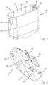
- Figs. 1 to 4 show a holder 11 for temporarily holding a lock 31, for example the one in FIG Figures 5 and 6 shown type, which can be inserted into the holder 11 along an insertion direction E.
- a lock 31 has a lock body 33 with a locking mechanism 35 and a spring-loaded button 37. Due to its bias, the button 37 protrudes beyond a side surface of the lock body 33 in a rest position and can be pressed in the direction of the lock body 33 counter to the bias along an actuation direction B, which runs transversely to the insertion direction E.
- such a lock 31 can have a striker 39, which can be locked in a closed position by means of the locking mechanism 35 on the lock body 33 and in a release position of the locking mechanism 35 can be brought into an open position in which at least one end of the striker 39 of the Lock body 33 can be solved.
- the striker 39 is designed as a wire rope, which can be pulled out of the lock body 33 against a spring force and has a clamp 41 at its free end, which can be locked on the lock body 33, as shown, for example, in FIG US D862198 S or US 4896517 is known.
- the locking mechanism 35 has a combination lock mechanism 43 with a plurality of rotatable code setting rings 45.
- the spring-loaded button 37 is used here to retract the striker 39 into the lock body 33 by means of spring force.
- Another spring-loaded button 47 of the lock body 33 is used to move the locking mechanism 35 into a release position. Both buttons 37, 47 can only be actuated when the code setting rings 45 have been set to be secret.
- the holder 11 is generally sleeve-shaped, with a circumferentially closed, essentially rectangular cross-section (with rounded corners) and with open ends in and against the insertion direction E.
- the holder 11 has a first holding section 13 and a second holding section 15, which corresponds to the first Holding portion 13 with respect to a receiving space 17 for the lock body 33 is diametrically opposite.
- the first and second holding sections 13, 15 are designed to grip around the lock body 33 inserted into the receiving space 17 along the insertion direction E on two opposite sides of the lock body 33 with respect to the actuation direction B essentially without play.
- the holder 11 has a respective securing opening 19, 21 on the two holding sections 13, 15, which is designed to positively engage the spring-loaded button 37 of the lock body 33 in its rest position protruding from the lock body 33, in order to thereby engage the lock body 33 to secure against unintentional loosening from the holder 11 against the direction of insertion E.
- the holder 11 At its end opposite to the insertion direction E, the holder 11 has two insertion bevels 23 in each case in an angular range corresponding to the securing openings 19, 21 (in relation to the insertion direction E).
- the holder 11 On its rear side, the holder 11 has a fastening section 25 with a fastening channel 27 running transversely to the insertion direction E, through which a fastening strap (not shown) for fastening the holder 11 to a pipe section of a two-wheeler can be passed.
- the spring-loaded button 37 of the lock body 33 is thus used to secure the lock 31 in the holder 11 when it is not in use.
- the button 47 could also be used for this (with the corresponding position and shape of the securing openings 19, 21).
- the button 37 or 47 of the lock body 33 has to be pressed briefly and thus are brought out of engagement with the securing opening 19, 21 of the holder 11.
- FIGs 7 and 8 show another portable lock 31, which has a lock body 33 with a locking mechanism 35 and a spring-loaded button 37 for actuating the locking mechanism 35, such as from FIG US D657657 S or EP 2019178 B1 is known.
- a lock 31 is also referred to as a folding lock or hinged bar lock and has a flexible striker in the form of a hinged bar.
Landscapes
- Engineering & Computer Science (AREA)
- Mechanical Engineering (AREA)
- Lock And Its Accessories (AREA)
- Battery Mounting, Suspending (AREA)
- Telephone Set Structure (AREA)
Applications Claiming Priority (1)
| Application Number | Priority Date | Filing Date | Title |
|---|---|---|---|
| DE102020116154.9A DE102020116154B3 (de) | 2020-06-18 | 2020-06-18 | Halterung für ein tragbares Schloss |
Publications (3)
| Publication Number | Publication Date |
|---|---|
| EP3925868A1 true EP3925868A1 (fr) | 2021-12-22 |
| EP3925868B1 EP3925868B1 (fr) | 2023-12-06 |
| EP3925868C0 EP3925868C0 (fr) | 2023-12-06 |
Family
ID=75690113
Family Applications (1)
| Application Number | Title | Priority Date | Filing Date |
|---|---|---|---|
| EP21170512.4A Active EP3925868B1 (fr) | 2020-06-18 | 2021-04-26 | Support pour une serrure portable |
Country Status (6)
| Country | Link |
|---|---|
| US (1) | US12281499B2 (fr) |
| EP (1) | EP3925868B1 (fr) |
| CN (1) | CN113818757B (fr) |
| AU (1) | AU2021202692A1 (fr) |
| DE (1) | DE102020116154B3 (fr) |
| TW (1) | TWI907434B (fr) |
Families Citing this family (2)
| Publication number | Priority date | Publication date | Assignee | Title |
|---|---|---|---|---|
| USD974873S1 (en) * | 2020-06-18 | 2023-01-10 | ABUS August Bremicker Söhne KG | Holder for locks |
| USD976081S1 (en) * | 2022-04-02 | 2023-01-24 | Yiwu Ledong Network Technology Co., Ltd. | Lock |
Citations (11)
| Publication number | Priority date | Publication date | Assignee | Title |
|---|---|---|---|---|
| US4896517A (en) | 1989-07-14 | 1990-01-30 | Ling Chong Kuan | Wire lock having self-retractable wire |
| EP1249566A2 (fr) * | 2001-04-10 | 2002-10-16 | ABUS August Bremicker Söhne KG | Dispositif de raccordement et procédé de mise en oeuvre d'un raccordement |
| US6467316B1 (en) * | 2000-08-24 | 2002-10-22 | Waterson Chen | Protective sleeve for a padlock |
| DE202004007927U1 (de) * | 2004-05-17 | 2004-07-15 | Büchel GmbH & Co. Fahrzeugteilefabrik KG | Halterung für ein Kabelschloss |
| JP2005179890A (ja) * | 2003-12-16 | 2005-07-07 | Nikko:Kk | U型ロック錠 |
| DE202005013390U1 (de) | 2005-08-24 | 2006-12-28 | ABUS August Bremicker Söhne KG | Halterung für ein Zweirad-Zubehör |
| USD657657S1 (en) | 2011-06-16 | 2012-04-17 | Abus August Bremicker Soehne Kg | Bicycle lock |
| EP2019178B1 (fr) | 2007-07-27 | 2013-08-14 | ABUS August Bremicker Söhne KG | Serrure à barres articulées |
| DE202014103690U1 (de) * | 2014-08-08 | 2014-08-22 | Trelock Gmbh | Universalhalter |
| CN204452673U (zh) * | 2015-03-09 | 2015-07-08 | 张玉龙 | 六折锁固定支架 |
| USD862198S1 (en) | 2017-03-14 | 2019-10-08 | ABUS August Bremicker Söhne KG | Combination lock |
Family Cites Families (20)
| Publication number | Priority date | Publication date | Assignee | Title |
|---|---|---|---|---|
| US657657A (en) | 1900-06-26 | 1900-09-11 | George Herbert Jr | Apparatus for feeding or delivering biscuits for packing. |
| US862198A (en) | 1906-12-27 | 1907-08-06 | Westinghouse Electric & Mfg Co | Suspension means for electric motors. |
| US4528998A (en) * | 1984-11-07 | 1985-07-16 | Jung Corporation | Button latch for telescoped tubes |
| US5156028A (en) * | 1991-04-08 | 1992-10-20 | Jiang Jy Chang | Padlock having a cable shackle and a locking means based on combination of numerals |
| US5662255A (en) * | 1995-11-30 | 1997-09-02 | Lu; Chien-Chzh | Lock holder for fastening to a motorcycle for carrying a motorcycle lock |
| US7131298B1 (en) | 2005-04-12 | 2006-11-07 | Trek Bicycle Corporation | Bicycle lock with multiple cable loops |
| CN201534586U (zh) | 2009-05-21 | 2010-07-28 | 詹显光 | 一种自行车锁支架 |
| CN101994433B (zh) | 2009-08-19 | 2013-07-31 | 金泰祥精密五金(昆山)有限公司 | 锁具 |
| DE102013102009B4 (de) | 2012-03-08 | 2021-05-06 | FAHRER Berlin GmbH | Schlosshalter |
| DE102012214211A1 (de) | 2012-08-09 | 2014-02-13 | ABUS August Bremicker Söhne KG | Halterung für ein Zweirad-Zubehör |
| US20160002958A1 (en) * | 2014-07-07 | 2016-01-07 | Federal Lock Co., Ltd. | Water-dust-proof case for lock |
| TWM509758U (zh) * | 2015-04-30 | 2015-10-01 | Lih Jaw Ind Co Ltd | 鎖具置放座 |
| DE202015103108U1 (de) | 2015-06-12 | 2015-07-17 | Büchel GmbH & Co. Fahrzeugteilefabrik KG | Halterung für ein Fahrradschloss |
| DE102015109860A1 (de) * | 2015-06-19 | 2016-12-22 | ABUS August Bremicker Söhne KG | Halterung |
| DE102015109997B4 (de) * | 2015-06-22 | 2022-10-13 | ABUS August Bremicker Söhne Kommanditgesellschaft | Halterung |
| DE102015116982A1 (de) | 2015-10-06 | 2017-04-06 | ABUS August Bremicker Söhne KG | Halterung für ein Bügelschloss |
| DE202017103486U1 (de) * | 2017-06-09 | 2017-07-10 | ABUS August Bremicker Söhne KG | Halterung für ein Zweirad-Schloss |
| TWM578724U (zh) | 2019-01-23 | 2019-06-01 | 昇詠鎖業有限公司 | Folding lock holder |
| US11608658B1 (en) * | 2019-07-12 | 2023-03-21 | Jay S. Derman | Padlock security 3 |
| US11319730B1 (en) * | 2019-07-12 | 2022-05-03 | Jay S. Derman | Padlock security 2 |
-
2020
- 2020-06-18 DE DE102020116154.9A patent/DE102020116154B3/de active Active
-
2021
- 2021-04-26 EP EP21170512.4A patent/EP3925868B1/fr active Active
- 2021-04-30 AU AU2021202692A patent/AU2021202692A1/en not_active Abandoned
- 2021-05-27 TW TW110119263A patent/TWI907434B/zh active
- 2021-06-08 US US17/341,634 patent/US12281499B2/en active Active
- 2021-06-18 CN CN202110678770.1A patent/CN113818757B/zh active Active
Patent Citations (11)
| Publication number | Priority date | Publication date | Assignee | Title |
|---|---|---|---|---|
| US4896517A (en) | 1989-07-14 | 1990-01-30 | Ling Chong Kuan | Wire lock having self-retractable wire |
| US6467316B1 (en) * | 2000-08-24 | 2002-10-22 | Waterson Chen | Protective sleeve for a padlock |
| EP1249566A2 (fr) * | 2001-04-10 | 2002-10-16 | ABUS August Bremicker Söhne KG | Dispositif de raccordement et procédé de mise en oeuvre d'un raccordement |
| JP2005179890A (ja) * | 2003-12-16 | 2005-07-07 | Nikko:Kk | U型ロック錠 |
| DE202004007927U1 (de) * | 2004-05-17 | 2004-07-15 | Büchel GmbH & Co. Fahrzeugteilefabrik KG | Halterung für ein Kabelschloss |
| DE202005013390U1 (de) | 2005-08-24 | 2006-12-28 | ABUS August Bremicker Söhne KG | Halterung für ein Zweirad-Zubehör |
| EP2019178B1 (fr) | 2007-07-27 | 2013-08-14 | ABUS August Bremicker Söhne KG | Serrure à barres articulées |
| USD657657S1 (en) | 2011-06-16 | 2012-04-17 | Abus August Bremicker Soehne Kg | Bicycle lock |
| DE202014103690U1 (de) * | 2014-08-08 | 2014-08-22 | Trelock Gmbh | Universalhalter |
| CN204452673U (zh) * | 2015-03-09 | 2015-07-08 | 张玉龙 | 六折锁固定支架 |
| USD862198S1 (en) | 2017-03-14 | 2019-10-08 | ABUS August Bremicker Söhne KG | Combination lock |
Also Published As
| Publication number | Publication date |
|---|---|
| EP3925868B1 (fr) | 2023-12-06 |
| US20210396050A1 (en) | 2021-12-23 |
| TWI907434B (zh) | 2025-12-11 |
| CN113818757A (zh) | 2021-12-21 |
| CN113818757B (zh) | 2025-02-25 |
| EP3925868C0 (fr) | 2023-12-06 |
| DE102020116154B3 (de) | 2021-05-27 |
| AU2021202692A1 (en) | 2022-01-20 |
| US12281499B2 (en) | 2025-04-22 |
| TW202202714A (zh) | 2022-01-16 |
Similar Documents
| Publication | Publication Date | Title |
|---|---|---|
| EP2942458B1 (fr) | Système de verrouillage de câble | |
| EP3109141B1 (fr) | Fixation | |
| EP1980446A1 (fr) | Dispositif destiné à fixer des produits de stockage dans un moyen de transport | |
| DE2942789A1 (de) | Permutationsschloss | |
| EP2668354B1 (fr) | Cadenas | |
| EP3925868B1 (fr) | Support pour une serrure portable | |
| DE102019113378A1 (de) | Gelenkschloss | |
| DE212020000789U1 (de) | Stützeinheit für einen Fahrradträger | |
| DE19532383A1 (de) | Mitführbefestigung eines Zubehörteils an einem mobilen Objekt | |
| DE102010025383A1 (de) | Schlaufenschloss | |
| EP3594436A1 (fr) | Cadenas | |
| DE3502069C2 (fr) | ||
| EP4012200A1 (fr) | Boulon d'encliquetage sollicité par ressort | |
| EP3538725A1 (fr) | Cadenas | |
| DE4016285C2 (fr) | ||
| AT390989B (de) | Tuerschloss mit verschiebbarem riegel und falle | |
| EP3741935B1 (fr) | Verrou d'aiguille à articulation | |
| DE102019113377A1 (de) | Gelenkschloss | |
| DE19519853A1 (de) | Vorrichtung zur Anbringung eines Kindersitzes an einem Fahrrad | |
| DE19706560A1 (de) | Ringschloß zum Sichern von beweglichen Gegenständen, insbesondere Zweirädern oder dergleichen Fahrzeuge | |
| DE102011113771A1 (de) | Schlaufenschloss | |
| EP1111164B1 (fr) | Dispositif de fixage pour carré de poignée | |
| DE102019124449B4 (de) | Abstandshalter | |
| EP2673430B1 (fr) | Dispositif permettant le blocage sécurisé d'une poignée rotative de vantail de porte et/ou de fenêtre | |
| DE19937126B4 (de) | Mitführbefestigung eines Zweiradschlosses an einem Zweirad |
Legal Events
| Date | Code | Title | Description |
|---|---|---|---|
| PUAI | Public reference made under article 153(3) epc to a published international application that has entered the european phase |
Free format text: ORIGINAL CODE: 0009012 |
|
| STAA | Information on the status of an ep patent application or granted ep patent |
Free format text: STATUS: THE APPLICATION HAS BEEN PUBLISHED |
|
| AK | Designated contracting states |
Kind code of ref document: A1 Designated state(s): AL AT BE BG CH CY CZ DE DK EE ES FI FR GB GR HR HU IE IS IT LI LT LU LV MC MK MT NL NO PL PT RO RS SE SI SK SM TR |
|
| B565 | Issuance of search results under rule 164(2) epc |
Effective date: 20211022 |
|
| STAA | Information on the status of an ep patent application or granted ep patent |
Free format text: STATUS: REQUEST FOR EXAMINATION WAS MADE |
|
| 17P | Request for examination filed |
Effective date: 20220622 |
|
| RBV | Designated contracting states (corrected) |
Designated state(s): AL AT BE BG CH CY CZ DE DK EE ES FI FR GB GR HR HU IE IS IT LI LT LU LV MC MK MT NL NO PL PT RO RS SE SI SK SM TR |
|
| GRAP | Despatch of communication of intention to grant a patent |
Free format text: ORIGINAL CODE: EPIDOSNIGR1 |
|
| STAA | Information on the status of an ep patent application or granted ep patent |
Free format text: STATUS: GRANT OF PATENT IS INTENDED |
|
| RIC1 | Information provided on ipc code assigned before grant |
Ipc: B62J 11/00 20200101ALI20230530BHEP Ipc: E05B 71/00 20060101ALI20230530BHEP Ipc: E05B 67/38 20060101ALI20230530BHEP Ipc: B62H 5/00 20060101AFI20230530BHEP |
|
| INTG | Intention to grant announced |
Effective date: 20230621 |
|
| GRAS | Grant fee paid |
Free format text: ORIGINAL CODE: EPIDOSNIGR3 |
|
| GRAA | (expected) grant |
Free format text: ORIGINAL CODE: 0009210 |
|
| STAA | Information on the status of an ep patent application or granted ep patent |
Free format text: STATUS: THE PATENT HAS BEEN GRANTED |
|
| AK | Designated contracting states |
Kind code of ref document: B1 Designated state(s): AL AT BE BG CH CY CZ DE DK EE ES FI FR GB GR HR HU IE IS IT LI LT LU LV MC MK MT NL NO PL PT RO RS SE SI SK SM TR |
|
| REG | Reference to a national code |
Ref country code: GB Ref legal event code: FG4D Free format text: NOT ENGLISH |
|
| REG | Reference to a national code |
Ref country code: CH Ref legal event code: EP |
|
| REG | Reference to a national code |
Ref country code: DE Ref legal event code: R096 Ref document number: 502021002106 Country of ref document: DE |
|
| REG | Reference to a national code |
Ref country code: IE Ref legal event code: FG4D Free format text: LANGUAGE OF EP DOCUMENT: GERMAN |
|
| U01 | Request for unitary effect filed |
Effective date: 20231206 |
|
| U07 | Unitary effect registered |
Designated state(s): AT BE BG DE DK EE FI FR IT LT LU LV MT NL PT SE SI Effective date: 20231211 |
|
| PG25 | Lapsed in a contracting state [announced via postgrant information from national office to epo] |
Ref country code: ES Free format text: LAPSE BECAUSE OF FAILURE TO SUBMIT A TRANSLATION OF THE DESCRIPTION OR TO PAY THE FEE WITHIN THE PRESCRIBED TIME-LIMIT Effective date: 20231206 |
|
| PG25 | Lapsed in a contracting state [announced via postgrant information from national office to epo] |
Ref country code: ES Free format text: LAPSE BECAUSE OF FAILURE TO SUBMIT A TRANSLATION OF THE DESCRIPTION OR TO PAY THE FEE WITHIN THE PRESCRIBED TIME-LIMIT Effective date: 20231206 |
|
| PG25 | Lapsed in a contracting state [announced via postgrant information from national office to epo] |
Ref country code: RS Free format text: LAPSE BECAUSE OF FAILURE TO SUBMIT A TRANSLATION OF THE DESCRIPTION OR TO PAY THE FEE WITHIN THE PRESCRIBED TIME-LIMIT Effective date: 20231206 Ref country code: NO Free format text: LAPSE BECAUSE OF FAILURE TO SUBMIT A TRANSLATION OF THE DESCRIPTION OR TO PAY THE FEE WITHIN THE PRESCRIBED TIME-LIMIT Effective date: 20240306 Ref country code: HR Free format text: LAPSE BECAUSE OF FAILURE TO SUBMIT A TRANSLATION OF THE DESCRIPTION OR TO PAY THE FEE WITHIN THE PRESCRIBED TIME-LIMIT Effective date: 20231206 |
|
| U20 | Renewal fee for the european patent with unitary effect paid |
Year of fee payment: 4 Effective date: 20240426 |
|
| PG25 | Lapsed in a contracting state [announced via postgrant information from national office to epo] |
Ref country code: IS Free format text: LAPSE BECAUSE OF FAILURE TO SUBMIT A TRANSLATION OF THE DESCRIPTION OR TO PAY THE FEE WITHIN THE PRESCRIBED TIME-LIMIT Effective date: 20240406 |
|
| PG25 | Lapsed in a contracting state [announced via postgrant information from national office to epo] |
Ref country code: CZ Free format text: LAPSE BECAUSE OF FAILURE TO SUBMIT A TRANSLATION OF THE DESCRIPTION OR TO PAY THE FEE WITHIN THE PRESCRIBED TIME-LIMIT Effective date: 20231206 |
|
| PG25 | Lapsed in a contracting state [announced via postgrant information from national office to epo] |
Ref country code: SK Free format text: LAPSE BECAUSE OF FAILURE TO SUBMIT A TRANSLATION OF THE DESCRIPTION OR TO PAY THE FEE WITHIN THE PRESCRIBED TIME-LIMIT Effective date: 20231206 |
|
| PG25 | Lapsed in a contracting state [announced via postgrant information from national office to epo] |
Ref country code: SM Free format text: LAPSE BECAUSE OF FAILURE TO SUBMIT A TRANSLATION OF THE DESCRIPTION OR TO PAY THE FEE WITHIN THE PRESCRIBED TIME-LIMIT Effective date: 20231206 Ref country code: SK Free format text: LAPSE BECAUSE OF FAILURE TO SUBMIT A TRANSLATION OF THE DESCRIPTION OR TO PAY THE FEE WITHIN THE PRESCRIBED TIME-LIMIT Effective date: 20231206 Ref country code: RO Free format text: LAPSE BECAUSE OF FAILURE TO SUBMIT A TRANSLATION OF THE DESCRIPTION OR TO PAY THE FEE WITHIN THE PRESCRIBED TIME-LIMIT Effective date: 20231206 Ref country code: IS Free format text: LAPSE BECAUSE OF FAILURE TO SUBMIT A TRANSLATION OF THE DESCRIPTION OR TO PAY THE FEE WITHIN THE PRESCRIBED TIME-LIMIT Effective date: 20240406 Ref country code: CZ Free format text: LAPSE BECAUSE OF FAILURE TO SUBMIT A TRANSLATION OF THE DESCRIPTION OR TO PAY THE FEE WITHIN THE PRESCRIBED TIME-LIMIT Effective date: 20231206 |
|
| PG25 | Lapsed in a contracting state [announced via postgrant information from national office to epo] |
Ref country code: PL Free format text: LAPSE BECAUSE OF FAILURE TO SUBMIT A TRANSLATION OF THE DESCRIPTION OR TO PAY THE FEE WITHIN THE PRESCRIBED TIME-LIMIT Effective date: 20231206 |
|
| PG25 | Lapsed in a contracting state [announced via postgrant information from national office to epo] |
Ref country code: PL Free format text: LAPSE BECAUSE OF FAILURE TO SUBMIT A TRANSLATION OF THE DESCRIPTION OR TO PAY THE FEE WITHIN THE PRESCRIBED TIME-LIMIT Effective date: 20231206 |
|
| REG | Reference to a national code |
Ref country code: DE Ref legal event code: R097 Ref document number: 502021002106 Country of ref document: DE |
|
| PLBE | No opposition filed within time limit |
Free format text: ORIGINAL CODE: 0009261 |
|
| STAA | Information on the status of an ep patent application or granted ep patent |
Free format text: STATUS: NO OPPOSITION FILED WITHIN TIME LIMIT |
|
| 26N | No opposition filed |
Effective date: 20240909 |
|
| PG25 | Lapsed in a contracting state [announced via postgrant information from national office to epo] |
Ref country code: MC Free format text: LAPSE BECAUSE OF FAILURE TO SUBMIT A TRANSLATION OF THE DESCRIPTION OR TO PAY THE FEE WITHIN THE PRESCRIBED TIME-LIMIT Effective date: 20231206 |
|
| PG25 | Lapsed in a contracting state [announced via postgrant information from national office to epo] |
Ref country code: MC Free format text: LAPSE BECAUSE OF FAILURE TO SUBMIT A TRANSLATION OF THE DESCRIPTION OR TO PAY THE FEE WITHIN THE PRESCRIBED TIME-LIMIT Effective date: 20231206 |
|
| REG | Reference to a national code |
Ref country code: CH Ref legal event code: PL |
|
| PG25 | Lapsed in a contracting state [announced via postgrant information from national office to epo] |
Ref country code: CH Free format text: LAPSE BECAUSE OF NON-PAYMENT OF DUE FEES Effective date: 20240430 |
|
| PG25 | Lapsed in a contracting state [announced via postgrant information from national office to epo] |
Ref country code: IE Free format text: LAPSE BECAUSE OF NON-PAYMENT OF DUE FEES Effective date: 20240426 |
|
| U20 | Renewal fee for the european patent with unitary effect paid |
Year of fee payment: 5 Effective date: 20250428 |
|
| PG25 | Lapsed in a contracting state [announced via postgrant information from national office to epo] |
Ref country code: CY Free format text: LAPSE BECAUSE OF FAILURE TO SUBMIT A TRANSLATION OF THE DESCRIPTION OR TO PAY THE FEE WITHIN THE PRESCRIBED TIME-LIMIT; INVALID AB INITIO Effective date: 20210426 |
|
| PG25 | Lapsed in a contracting state [announced via postgrant information from national office to epo] |
Ref country code: HU Free format text: LAPSE BECAUSE OF FAILURE TO SUBMIT A TRANSLATION OF THE DESCRIPTION OR TO PAY THE FEE WITHIN THE PRESCRIBED TIME-LIMIT; INVALID AB INITIO Effective date: 20210426 |
|
| PG25 | Lapsed in a contracting state [announced via postgrant information from national office to epo] |
Ref country code: GR Free format text: LAPSE BECAUSE OF FAILURE TO SUBMIT A TRANSLATION OF THE DESCRIPTION OR TO PAY THE FEE WITHIN THE PRESCRIBED TIME-LIMIT; INVALID AB INITIO Effective date: 20210426 |
|
| GBPC | Gb: european patent ceased through non-payment of renewal fee |
Effective date: 20250426 |
|
| PG25 | Lapsed in a contracting state [announced via postgrant information from national office to epo] |
Ref country code: GB Free format text: LAPSE BECAUSE OF NON-PAYMENT OF DUE FEES Effective date: 20250426 |