EP3925932A1 - Geschlossene herstellung von pharmazeutisch reinen kristallen - Google Patents
Geschlossene herstellung von pharmazeutisch reinen kristallen Download PDFInfo
- Publication number
- EP3925932A1 EP3925932A1 EP20180574.4A EP20180574A EP3925932A1 EP 3925932 A1 EP3925932 A1 EP 3925932A1 EP 20180574 A EP20180574 A EP 20180574A EP 3925932 A1 EP3925932 A1 EP 3925932A1
- Authority
- EP
- European Patent Office
- Prior art keywords
- drying
- crystal
- vacuum
- temperature
- solution
- Prior art date
- Legal status (The legal status is an assumption and is not a legal conclusion. Google has not performed a legal analysis and makes no representation as to the accuracy of the status listed.)
- Withdrawn
Links
Images




Classifications
-
- C—CHEMISTRY; METALLURGY
- C01—INORGANIC CHEMISTRY
- C01G—COMPOUNDS CONTAINING METALS NOT COVERED BY SUBCLASSES C01D OR C01F
- C01G45/00—Compounds of manganese
- C01G45/06—Halides; Oxyhalides
-
- B—PERFORMING OPERATIONS; TRANSPORTING
- B01—PHYSICAL OR CHEMICAL PROCESSES OR APPARATUS IN GENERAL
- B01D—SEPARATION
- B01D9/00—Crystallisation
- B01D9/0004—Crystallisation cooling by heat exchange
- B01D9/0013—Crystallisation cooling by heat exchange by indirect heat exchange
-
- B—PERFORMING OPERATIONS; TRANSPORTING
- B01—PHYSICAL OR CHEMICAL PROCESSES OR APPARATUS IN GENERAL
- B01D—SEPARATION
- B01D9/00—Crystallisation
- B01D9/0018—Evaporation of components of the mixture to be separated
- B01D9/0022—Evaporation of components of the mixture to be separated by reducing pressure
-
- B—PERFORMING OPERATIONS; TRANSPORTING
- B01—PHYSICAL OR CHEMICAL PROCESSES OR APPARATUS IN GENERAL
- B01D—SEPARATION
- B01D9/00—Crystallisation
- B01D9/0036—Crystallisation on to a bed of product crystals; Seeding
-
- B—PERFORMING OPERATIONS; TRANSPORTING
- B01—PHYSICAL OR CHEMICAL PROCESSES OR APPARATUS IN GENERAL
- B01D—SEPARATION
- B01D9/00—Crystallisation
- B01D9/0059—General arrangements of crystallisation plant, e.g. flow sheets
-
- B—PERFORMING OPERATIONS; TRANSPORTING
- B01—PHYSICAL OR CHEMICAL PROCESSES OR APPARATUS IN GENERAL
- B01D—SEPARATION
- B01D9/00—Crystallisation
- B01D9/0063—Control or regulation
-
- C—CHEMISTRY; METALLURGY
- C01—INORGANIC CHEMISTRY
- C01G—COMPOUNDS CONTAINING METALS NOT COVERED BY SUBCLASSES C01D OR C01F
- C01G1/00—Methods of preparing compounds of metals not covered by subclasses C01B, C01C, C01D, or C01F, in general
- C01G1/06—Halides
-
- B—PERFORMING OPERATIONS; TRANSPORTING
- B01—PHYSICAL OR CHEMICAL PROCESSES OR APPARATUS IN GENERAL
- B01D—SEPARATION
- B01D9/00—Crystallisation
- B01D9/004—Fractional crystallisation; Fractionating or rectifying columns
- B01D9/0045—Washing of crystals, e.g. in wash columns
-
- B—PERFORMING OPERATIONS; TRANSPORTING
- B01—PHYSICAL OR CHEMICAL PROCESSES OR APPARATUS IN GENERAL
- B01D—SEPARATION
- B01D9/00—Crystallisation
- B01D9/0081—Use of vibrations, e.g. ultrasound
Definitions
- the present invention relates to means and methods for producing crystals or crystalline substances in a contained vessel.
- crystals or crystalline substances which are useful as pharmaceutical ingredients, can be manufactured.
- Crystallization is conventionally referred to as a process of the formation of solid crystals, precipitating from a solution or melt or rarely deposited directly from a gas.
- the crystallization process consists of two major events, namely, nucleation and crystal growth.
- Nucleation is the step wherein the solid molecules disperse in the solvent start to form clusters on the nanometre scale.
- the stable clusters are denominated "nucleate". Whenever the clusters are not stable, they re-dissolve. In order for the clusters to become stable, they have to reach a critical size. The critical size depends on operating conditions such as temperature, super saturation, etc.
- the atoms in the substance to be crystallized are arranged in a defined manner that defines the crystal structure.
- crystal structure refers to the relative arrangement of the atoms rather than the macroscopic properties of the crystal, which is in turn defined by parameters such as size and shape.
- the properties of the crystal are typically the result of the (internal) crystal structure.
- the crystal growth occurs, which is the growth of a nucleate that succeeds in achieving the critical cluster size.
- the driving force of the crystallization process comprising nucleation and crystal growth is the super saturation.
- the size of the crystals depends upon the conditions to favour either the nucleation or the growth of the nuclei.
- polymorphism a phenomenon that has the ability to crystallize with different crystal structures, a phenomenon called polymorphism.
- Each polymorph represents a different thermodynamic solid state and crystal polymorphs of the same compound exhibit different physical properties, e.g., the solution rate, shape, melting point, etc.
- Polymorphism is of a major importance in industrial manufacture of crystalline products.
- Crystallization may be used in the industry in order to provide highly purified products, in order to obtain salts or other crystalline end products.
- the solution For a crystallization, or re-crystallization to occur from a solution, the solution must be supersaturated. This means that the solution has to contain more solute entities (molecules or ions) dissolved than it would contain under the equilibrium, i.e., the saturated solution.
- Supersaturated conditions can be achieved by various methods such as solution cooling, addition of secondary solvents to reduce solubility of the solute (anti-solvent or drown out technique), chemical reaction or change in pH. All of these methods are employed in industrial practice. In addition, solvent evaporation can be used.
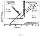
- Figure 1 exhibits a saturation curve, i.e. graph, which shows the borderline between unsaturated and supersaturated solution.
- a saturation curve i.e. graph
- a so-called meta-stable region occurs between the saturation curve and the super saturation curve.
- a spontaneous crystallization of the solid takes place in this meta stable region.
- the temperature may be rapidly decreased without changing the amount of substance per volume of solution (so-called cooling crystallization)
- the amount of substance per volume of solvent may be rapidly increased at a constant temperature, e.g. by vaporization (so-called vaporization crystallization), or both temperature and amount of substance per volume of solvent are rapidly changed simultaneously, i.e. the temperature is decreased, while the amount of substance per volume is increased (so-called vacuum crystallization).
- a seed crystal is then introduced in order to induce the crystallization process.
- vaporization crystallization equipment is the so-called circulating liquid evaporator crystallizer.
- a screw pump draws the circulating liquid down inside the tube side of the condensing stream heater. The heated liquid then flows into the vapour space where flash evaporation occurs resulting in super saturation. The vapour leaving is condensed.
- the supersaturated liquid flows down the down flow tube and then up through the bed of fluidized and agitated crystals. The crystals grow in size.
- the leaving saturated liquid then goes back as a recycle stream to the heater where it is joined by the entering fluid.
- the larger crystals settle out and the slurry of crystals and mother liquid is withdrawn as a product.
- One tank crystallizer example for a vacuum crystallizer is the so-called circulating magma vacuum crystallizer.
- a suspension (magma) of crystals is circulated - without separating the liquid from the solid - out of the main body of the apparatus through a circulating pipe by a screw pump.
- the magma flows through a heater, where the temperature is raised.
- the heated liquid then mixes with body slurry and boiling occurs at the liquid surface. This causes super saturation in the swirling liquid near the surface, which deposits in the swirling suspended crystals until they leave again via the circulating pipe.
- the crystals are drawn off near the bottom of the main body (vessel). The vapours leave through the top.
- Hydrates are inorganic or organic substances that contain crystal bound water.
- the water molecules are combined with the molecule in a definite ratio as an integral part of the crystal.
- the notation of hydrate compounds is "nH 2 O", wherein n is the number of water molecules per molecule of salt. "n” is usually a low integer although it is possible that fractioned values exist. In a monohydrate n is 1; in a hexa-hydrate n is 6, etc.
- the stability of hydrates is generally determined by the nature of the compounds, their temperature and the relative humidity if they are exposed to an open surrounding. Inorganic and organic compounds exist in various hydrates.
- Manganese chloride tetra-hydrate (MnCl 2 ⁇ 4H 2 O) which can be used as an active pharmaceutical ingredient (API) especially in parenteral preparations.
- MnCl 2 ⁇ 4H 2 O Manganese chloride tetra-hydrate
- API active pharmaceutical ingredient
- Types of possible contaminations contain inorganic impurities, for example heavy metals and / or organic impurities for example bacterial endotoxins. This includes avoidance of microbial exposition.
- Typical API crystalline substances are metal salts, which may be used for parenteral preparations, such as injection solutions with a single trace element or a multi trace element combination; parenteral nutritions; sterile oral solutions; aseptic topic preparations, e.g. formulated as lotion, gel or cream.
- Crystalline substances requiring high homogeneity and purity may be selected from Sodium selenite pentahydrate; Sodium selenite anhydrous; Copper chloride di-hydrate; Chromium chloride hexa-hydrate; Manganese chloride tetra-hydrate; Iron(II) chloride tetra-hydrate; Sodium molybdate di-hydrate; Zinc chloride di-hydrate and other metal salts.
- Metal chloride hydrates are good examples that there is a need in the field for new means and a new manufacturing method for preparing well-defined and highly pure crystals, preferably useful in the pharmaceutical field. There is also a need to provide such metal salts meeting the pharmacopeia standards.
- Manufacturing method and device are the results of a sophisticated research program and a highly laborious process, in which several unexpected experimental difficulties had to be overcome.
- the details of the research program and obstacles, which needed to be overcome are shown in the Example section.
- the new method and corresponding new device allows the manufacturing of crystalline products in one closed vessel under ultra clean and aseptic conditions.
- the new manufacturing method as well as the new device are therefore not limited to the production of metal chloride hydrates, but open a new possibility for the reliable and manufacturing of pharmaceutical grade, highly pure ("first class") crystals.
- a manufacturing method which employs vacuum crystallization in combination with a drying process, in which cooling to remove solvent from an obtained crystal cake is employed, preferably by using a condenser trap, more preferably an ice condenser. Solvent from the crystal cake is frozen in the condenser trap and thereby removed from the crystal cake.
- Vacuum Crystallization is a process, wherein to a saturated solution fed to a closed vessel vacuum is applied and the solution evaporates and thereby cools adiabatically, resulting in crystallization.
- a “condenser trap” (synonyms: condensation trap, condensing trap, condensate trap) is a chamber, through which the solvent in its gasoline form is guided and in which the solvent can be condensed or frozen.
- solvent from the crystal cake is frozen (and therewith trapped) in the condenser trap.
- the condenser trap is preferably kept at a temperature between -10 °C and -50 °C, more preferably between -15 °C and -40 °C, most preferably -20 °C and -30°C, in particular, if water is the solvent.
- the condenser trap is an ice condenser and the solvent is water.
- substances to be crystallized may be dissolved in acidic or alkaline aqueous medium.
- water is the solvent of the acidic or alkaline aqueous medium and water is trapped and frozen in the condensing trap.
- Freezing of the solvent "in the condenser trap” means that the solvent evaporated from the crystal cake is frozen and thereby trapped in the condenser trap.
- the capacity of the condenser trap is so high that at least five times the amount of the remaining solvent in the reaction vessel beyond the amount of the crystal solvent (preferably water) can be frozen and thereby trapped, more preferably at least two times the amount of the remaining solvent in the reaction vessel beyond the amount of the crystal solvent (preferably water) can be frozen and thereby trapped, most preferably at least the amount of the remaining solvent in the reaction vessel beyond the amount of the crystal solvent (preferably water) can be frozen and thereby trapped.
- drying takes place under applying vacuum.
- vacuum solvent from the crystal cake is evaporated and trapped and thereby frozen in the condenser trap.
- the vacuum is chosen so that the solvent is evaporated but the crystal cake is not dissolved.
- the reaction vessel is held at a pressure of 0 and 500 mbar, preferably 0.5 and 100 mbar, more preferably 1-50 mbar, most preferably 1 and 10 mbar.
- the temperature in the vessel during drying is controlled.
- the temperature is controlled to be on the one hand sufficiently high for the evaporation of the solvent, but on the other hand low enough so that the crystal cake is not dissolved by too much heating.
- the reaction vessel is held at a temperature between 0 and 50 °C; preferably, 0 and 40 °C, more preferably 10 and 30 °C, more preferably 20 °C and 40 °C, even more preferably 25 °C and 30 °C. Most preferably, the reaction vessel is held between 0 °C and 40 °C at a pressure of between 0,5 mbar and 10 mbar.
- the "temperature is held at” means that a heater outside the vessel is set to a temperature value within the mentioned temperature range.
- the heater outside the vessel is an external heater of the vessel, like a thermo unit (such as thermo unit (5)), e.g. a double jacket.
- the method according to the present invention is performed in a contained reaction vessel.
- a "contained reaction vessel” (“or single pot”) is a closed system. It may be in closed connection with other vessels, but is shielded against the environment. Since method and device of the present invention allow for the production of crystals in a "single pot" reaction, the reaction - from beginning to the end - is shielded against contaminations from outside.
- the present invention provides a method for manufacturing a crystalline substance, wherein the method employs vacuum crystallization of a solution of the substance to be crystallized, comprising
- the method comprises
- the solvent e.g. water
- the solvent may still be used.
- organic solvents are typically used.
- drying step d) comprises a period of drying, which is performed without the introduction of mechanical energy, more preferably without continuous stirring, wherein only upon the formation of an incrusted layer on the crystal cake (i.e. crystal mush), the incrusted layer is broken by slow stirring periods, preferably involving not more than 10, 5 or 3 revolutions per hour, slow stirring of less than 3 revolutions per hours, less than 2 revolution per hour, or less than 1 revolution per 2 hours.
- This type of drying is called "static drying".
- the static drying preferably continues up to the removal of the solvent, preferably water, to a degree wherein the amount of solvent is so low that the local (i.e. partial) (re-)dissolution of the crystal mush or crystal cake is no longer possible.
- the solvent preferably water
- vacuum and/or temperature are controlled so that the re-dissolution of the crystal cake is avoided.
- cooling of evaporated solvent is performed by using a condenser trap, more preferably by using an ice condenser, which is connected to the reaction vessel during the static drying step, preferably during the whole drying step.
- the solvent is thereby frozen and trapped in the condenser trap.
- the reaction vessel is held at a pressure of 0 and 500 mbar, preferably 0.5 and 100 mbar, more preferably 1-50 mbar, most preferably 1 and 10 mbar.
- the temperature in the vessel during static drying is controlled.
- the temperature is controlled to be on the one hand sufficiently high for the evaporation of the solvent, but on the other hand low enough so that the crystal cake is not dissolved by too much heating.
- the reaction vessel is held at a temperature between 0 and 50 °C; preferably, 0 and 40 °C, more preferably 10 and 30 °C, more preferably 20 °C and 40 °C, even more preferably 25 °C and 30 °C. Most preferably, the reaction vessel is held between 0 °C and 40 °C at a pressure of between 0,5 mbar and 10 mbar.
- the methods of the present invention may comprise the following steps of
- the present invention may also contain a step of synthesizing the crystal from raw material.
- One way of obtaining crystals is by way of vacuum crystallization from a supersaturated solution.
- the crystal cake is dried, wherein a condenser trap is employed.
- a supersaturated solution of the substance to be crystalized may be obtained in various ways.
- the solution of the substance to be crystalized is concentrated by vacuum distillation to obtain a supersaturated solution.
- distillation is a process of separating substances, e.g. the solvent, from a liquid containing mixture by using selective boiling and condensation.
- “Vacuum distillation” in the present invention is distillation under reduced pressure to evaporate solvent and condensing evaporated solvent, preferably in a collection vessel, which may be connected to a cooling head.
- “Vacuum distillation” in the present invention thus, comprises applying vacuum and condensing the evaporated solvent, preferably in a collection vessel, which may be connected to a cooling head.
- the supersaturated solution shall have a concentration in the metastable zone as identified in lab-scale experiments (see Example 2).
- the raw substance to be crystalized may be inserted into the reaction vessel (e.g. a glass reactor) using a suction hose set.
- the distillate quantity is calculated to control the vacuum distillation.
- the substance is then dissolved in a solvent.
- the solution may be filtered using an ultra-filter to remove impurities. This is described further herein below.
- the distillation may be carried out under normal pressure, but is typically carried out under vacuum, preferably at 1-100 mbar, more preferably 5-50 mbar, most preferably 40-50 mbar.
- the temperature of a heater outside the reaction vessel to heat the solution in the vessel is set to a value beyond boiling temperature of the solution.
- a double jacket surrounding the reaction vessel with a temperature of 135 - 145 °C may be used.
- the temperature of the solution may be between 20 - 70 °C, more preferably between 40 and 50 °C.
- samples may be taken via a sampling flange of the vessel using a sterile suction device for sampling the liquid, crystal mush (i.e. crystal cake) or crystalline samples from the vessel.
- a syringe may be used as well.
- a first sample may be taken during distillation from the non-saturated, saturated or supersaturated solution and/or after distillation from the obtained supersaturated solution.
- the distillation is stopped after reaching the calculated distillate quantity by breaking the vacuum.
- the solution is heated to a temperature higher than the distillation temperature, e.g. 70 - 80 °C, preferably under normal pressure.
- the temperature of a heater (e.g. a double jacket) outside the reaction vessel to heat the solution in the vessel is set to a value beyond boiling temperature of the solution.
- a double jacket surrounding the reaction vessel with a temperature of 135 - 145 °C may be used.
- steam might be injected to dissolve any precipitates.
- the steam is preferably water steam.
- the method of the present invention may contain a step of removing contaminants.
- Contaminants can be organic contaminant, which may be removed by prefiltration or filtration. Contaminants may also be bacteria or bacterial endotoxins, all of which may be removed by particular membrane filters or by ultrafiltration.
- Purification can also be by removal of inorganic contaminants via crystallization. This can be performed during the removal of the mother liquor containing the salt or inorganic contaminants. Alternatively, a recrystallization step may be performed before the method of claim 1 to remove inorganic contaminants by crystalizing the intended substance and removing the contaminants from the supernatant.
- microporous membrane filter capsules and ultrafiltration modules may be employed during the filtration trials.
- Pre-filtration shall retain particles and various macroscopic impurities.
- Ultrafiltration (10000 Dalton cut off) and bacterial filtration shall remove bacterial endotoxins and microbiological contaminants.
- the filter material has to show a resistance against acidic and halogen solutions.
- Suitable materials were identified e.g. PTFE (polytetrafluoroethylene), ECTFE (ethylene chlorotrifluoroethylene), PP (polypropylene) and PES (polyethersulfone).
- PTFE polytetrafluoroethylene
- ECTFE ethylene chlorotrifluoroethylene
- PP polypropylene
- PES polyethersulfone
- PES filter membrane material showed excellent performance, particularly under the harsh conditions (very acidic milieu), and was selected to be used for all filters, i. e. particle and bacterial filtration as well as ultrafiltration.
- PES polyethersulfone
- Transition metal halogenide solutions feature a relatively high ionic strength at high concentrations, the filtration performance depends on the used concentration. In order to achieve reasonable filtration times and economic filter areas, solution concentrations of approximately 25 - 30 % (m/m) were used.
- Pre-filter capsules (0.6 ⁇ m) and membrane filter capsules (0.2 ⁇ m) may be used for particle and membrane filtration as subsequent processing steps after a successfully performed synthesis as well as before and after ultrafiltration, respectively.
- the intermediates - e.g. salt (e.g. MnCl 2 ,) solution from synthesis and salt (e.g. MnCl 2 ,) ultrafiltrate - may be filtered over sterile mono layer 0.6 (filter area: e.g. 180 cm 2 ; membrane: polyethersulfone) and 0.2 ⁇ m membrane filter capsules (filter area: e.g. 480 cm 2 ; membrane: polyethersulfone).
- pre-rinsing and flushing conditions with AP as well as the applied flow rates for the various product solutions are defined.
- ultrafiltration In order to remove organic impurities, e.g. bacterial endotoxins, ultrafiltration (cut off 10000 Daltons) may be performed after synthesis. The ultrafiltration should take place after synthesis and membrane filtration (0.2 ⁇ m).
- the filtration system may be assembled with an UF module, a 1000 cm 2 polyethersulfone membrane and a molecular weight cut off 10000 Daltons.
- the Cadence Omega UF module was intended to be single use and will be discarded after each production run.
- the feed flow rate and the corresponding retentate pressure for the ultrafiltration of the MnCl 2 tetra-hydrate solution as well as the permeate pressure were defined.
- the crystallisation technique requires a defined, relatively high concentration of the MnCl 2 tetra-hydrate solution.
- concentration range the so-called metastable zone of MnCl 2 solution is situated - see Example 2.
- This zone describes a phase of the mother liquor with a defined temperature that is supersaturated - but has not yet responded with spontaneous nucleation with a certain finite time.
- Crystallization is initiated by nucleation in a supersaturated solution. "Nucleation” is the formation of crystal nuclei.
- the temperature may be regulated or controlled, e.g. the solution is cooled from outside, e.g. the double jacket temperature is set to 1 °C.
- the target temperature in the supersaturated solution is higher than the outside temperature of the heater (e.g. double jacket), not particularly specified and depends on the substance to be crystalized.
- the pressure may be set to vacuum, preferably to 10-500 mbar, more preferably 40 to 100 mbar. Due to the vacuum, the preparation begins to boil and is further cooled down.
- the solution is stirred, e.g. the stirring speed is set to 10-100 RPM, preferably 40- 60 RPM, more preferably 45-55 RPM.
- gas bubbles of the boiling solvent are created which act as crystal seeds.
- other types of crystal seeds may be created by cavitation, e.g. by introducing inert gas.
- the vacuum is broken and the stirring speed is reduced, e.g. to 25 RPM or lower.
- the temperature is, then, typically above room temperature.
- a crystallization phase may be run, preferably under normal pressure or containing a period of cooling under normal pressure.
- Crystallization or “Crystallization phase” is the phase during which crystals grow.
- Example 4 shows two salts for which vacuum was drawn during the Crystallization Phase ("Phase 2 distillation" for FeCl 2 ⁇ 4 H 2 O and Na 2 MoO 4 ⁇ 4 H 2 O).
- Phase 2 distillation for FeCl 2 ⁇ 4 H 2 O and Na 2 MoO 4 ⁇ 4 H 2 O.
- Other crystals such as those further exemplified in Examples 3 and 4, grow well or even best under normal pressure without drawing vacuum.
- the crystallization phase is performed by cooling the solution, e.g. to 10 °C.
- the solution is allowed to continue crystallizing for a long time period, preferably at least one hour, more preferably at least 5 hours, or most preferably at least 10 hours.
- the solution is allowed to continue crystallizing while stirring, e.g. with 50, 35 or 25 RPM or lower.
- the solution is allowed to continue crystallizing under continuous decrease of temperature with a constant cooling rate or a stepwise decrease of temperature.
- a constant cooling rate may preferably use a decrease of temperature at a range of 1 to 5 °C per minute, more preferably 2 to 4 °C per minutes, most preferably 2.5 to 3.5 °C per minutes;
- cooling is performed stepwise: At the beginning the temperature is decreased fast, e.g. at a range of 1 to 5 °C per minute, more preferably 2 to 4 °C per minutes, most preferably 2.5 to 3.5 °C per minutes; after reaching room temperature of 25 °C slowly, e.g. 0.1 to 0.5 °C per minutes to induce further growth of crystals;
- the target temperature of the cooling step is preferably 0 to 10 °C, the temperature being the temperature in the solution.
- the target temperature may be controlled by setting temperatures in an external heating unit. The temperatures of the external heating units may be reduced stepwise, continuously or may be set only once.
- the solvent may be removed by vacuum distillation during cooling, which may - for some crystals, e.g. as shown in Example 4 - improve crystal growth.
- the vacuum has a cooling effect so that the external temperature does not need to be set to temperatures as low as under normal pressure.
- the temperature of an external heating unit may be set to between 80 and 1°C, preferably 30 °C and 1°C, more preferably between 15 and 5°C.
- the temperature of an external heating unit may be set to between 100 °C and 30°C, preferably 90 °C and 60 °C.
- the liquid i.e. the mother liquor
- the liquid may be separated from the grown crystals (i.e. the crystal mass present in the remaining liquid or the crystal cake present in the remaining liquid) to obtain a crystal cake, e.g. via the bottom valve of the reaction vessel using inert gas overpressure.
- the pressure is not more than 1500 mbar.
- the inert gas is preferably nitrogen or argon.
- the stirrer may be rotated briefly (e.g. at 25 RPM), if necessary.
- a washing step maybe performed to remove further and/or remaining impurities.
- the crystal cake needs to be dried to end up with the final product ("crystalline powder").
- the crystalline substance may be tested for its stoichiometry by conventional measurement techniques. They may be conducted inside the vessel or by deriving a small sample from the vessel conducting a measurement outside.
- the temperature is preferably kept in a low range without modulation.
- the temperature in the static drying step is preferably lower than in the dynamic drying step.
- the temperature can be increased at the beginning of the dynamic drying step.
- the temperature may be lowered.
- the static drying step takes between 2 and 24 hours, more preferably between 6 and 18 hours, most preferably between 11 and 13 hours, alternatively most preferably between 6 - 8 hours.
- Drying may be interrupted optionally by the introduction of the inert gas into the reaction vessel Nitrogen or Argon are preferred inert gases.
- the static drying step includes short intervals of very short movements of the stirrer, each less than one, less than two, less than three revolutions. Such movements may take place after intervals of resting which are at least one, at least one and a half, at least two, at least two and a half, or at least three hours. There may be several sequential intervals of resting and moving.
- the goal of the static drying step is to obtain a significant reduction of the residual solvent content so that the dissolution of the crystals can no longer occur.
- the condenser trap e.g. the ice condenser
- the condenser trap is set to a temperature suitable to freeze out the remainder of the solvent, between -10 °C and -50 °C, more preferably between -15 °C and -40 °C, most preferably -20 °C and -30°C, in particular, if water is the solvent.
- the crystal cake is stirred briefly to break up the surface.
- the pressure is set to vacuum.
- static drying takes place under applying vacuum.
- solvent from the crystal cake is evaporated and trapped and thereby frozen in the condenser trap.
- the vacuum is chosen so that the solvent is evaporated but the crystal cake is not dissolved.
- the reaction vessel is held at a pressure of 0 and 500 mbar, preferably 0.5 and 100 mbar, more preferably 1-50 mbar, most preferably 1 and 10 mbar.
- the temperature in the vessel during drying is controlled.
- the temperature is controlled to be on the one hand sufficiently high for the evaporation of the solvent, but on the other hand low enough so that the crystal cake is not dissolved by too much heating.
- the reaction vessel is held at a temperature between 0 and 50 °C; preferably, 0 and 40 °C, more preferably 10 and 30 °C, more preferably 20 °C and 40 °C, even more preferably 25 °C and 30 °C. Most preferably, the reaction vessel is held between 0 °C and 40 °C at a pressure of between 0,5 mbar and 10 mbar.
- the crystal cake is dried, wherein the crystal surface is broken up preferably in approx. 2-hour intervals (1 to 3 h) by stirring briefly, e.g. at 25 RPM. Stirring duration time must not be longer than 10 s per stirring period.
- a drying step beyond the static drying step may be performed. This further drying is denominated the "dynamic drying step". Here, stirring is performed.
- the dynamic drying step is conducted after the amount of water is so low that even partial dissolution of the crystal mush, not even inside the crystal mush, is no longer possible. This is e.g. the case if the crystal solvent, preferably crystal water, is less than 5% higher than the percentage of crystal water (w/w) as compared to the crystal water in the perfect crystal stoichiometry.
- the stirrer is preferably switched-on continuously.
- the other process parameters may remain unchanged or may be modified within the parameter ranges specified for static drying.
- stirring velocity may be increased with time or with the progress of drying.
- the temperature can be modulated during the dynamic drying step.
- the dynamic drying step duration is 6 - 36 hours, more preferably between 8 and 24 hours, most preferably between 12 and 18 hours.
- the velocity of the stirring is 5 -50 RPM, preferably 25 - 50 RPM;
- the pressure conditions of the vacuum are 1 - 10 mbar, preferably 1 to 5 mbar;
- the temperature is 10 - 40 °C, preferably 20 - 40 °C, more preferably 20 - 30 °C.
- the goals of the dynamic drying step are removal of excess water, precise adjustment of crystal water, obtaining of a homogenous batch of the crystal.
- the end of the dynamic drying process may be marked by the vessel temperature being raised close to the temperature of the heater outside the vessel.
- the pressure is increased, e.g. set to 700 mbar.
- the obtained crystal powder is mixed well for at least 15 min at 50 RPM.
- the process is continued with steam injection and subsequent post-drying.
- Additional solvent can be inserted in case of "over drying” by an optional injection of solvent in gasoline form, preferably by a steam treatment, wherein water is added.
- static and/or dynamic drying steps are continued, preferably sequentially, but in shorter time intervals than during the first static and/or dynamic drying steps.
- only dynamic drying step is performed during "post drying" without a static drying step. Post-drying is carried out to adjust the residual moisture of the crystal powder according to the determined drying loss.
- the vessel may be prepared for steam injection.
- the crystal powder is continuously stirred for at least 10 minutes (e.g. at 50 RPM). After performing the steam injection, at least one post-drying cycle needs to be performed.
- a sample of the crystal powder may be taken for analysis purposes, e.g. drying loss is determined.
- Post-drying may be carried out by continuing static and/or dynamic drying steps.
- post-drying is in 30 - 60 minute cycles according to the following conditions and parameters:
- the drying loss may be determined. To do this, the stirrer is switched off and the vacuum is broken.
- a sample of the crystal powder may be taken for analysis purposes, e.g. drying loss is determined.
- the production method may continue by removing the final product ("powder phase") from the reaction vessel.
- a suction device may be used to discharge the powder phase of the product via a connection flange of the vessel.
- the suction device may designed like a vacuum cleaner with suction hose that is inserted into the reaction vessel. Via the suction hose, the final product is transferred into a product bag outside the reaction vessel.
- the product bag is implemented in a further vessel, which may be kept under inert gas.
- the product bag is preferably air-permeable.
- the product bag is sterile or has been sterilized.
- the product bag may be sterilized by gamma irradiation.
- the net weight of the product (“powder phase") is determined.
- a device comprising
- the "vessel” referred to in the methods of the present invention may be the “reactor (2)" of the device of the present invention.
- the “vacuum unit” (1) may be or may include a conventional vacuum pump suitable to reach pressures between 0,1 and 1013 mbar.
- the vacuum unit is suitable to draw vacuum and to create overpressure in the reactor (2) and/or the condenser trap (3). More preferably, the vacuum pump is resistant to acids and/or bases, more preferably the vacuum pump is a diaphragm pump.
- the "condenser trap” (3) is a chamber, through which the solvent in its gasoline form is guided and in which the solvent may be condensed and frozen. "Connection lines” allow for the transfer of substances, e.g. gases, fluids and solids.
- Connection lines may be closed, if necessary.
- Connection line (1a) may be arranged to directly connect vacuum unit (1) and condenser trap (3) or may be arranged to directly connect vacuum unit (1) and reactor (2).
- connection lines (1a) may be two connection lines (1a), to have both alternatives present in the device of the invention.
- a device comprising
- the "thermo unit” (5) is suitable for the heating and cooling of the reactor and the substances within the reactor.
- the reactor is embedded into the "thermo unit", which is preferably a double jacket.
- the thermo unit (5) is a heater. More preferably, the thermo unit (5) is a heater and cooler. Most preferably, the thermo unit (5) is a double jacket, e.g. a commercially available double jacket.
- the devices of the present invention further include a filter base area (4).
- the "filter base area” (4) allows for the filtering of liquid-solid-mixtures in the reactor (2) and the subsequent removal of liquid, e.g. mother liquor, from the bottom of the reactor (2).
- the "filter base area (4) is preferably at the bottom of the reactor (2).
- the devices of the present invention include a reactor inlet (2a) and a reactor outlet (2b). If a filter base area (4) is present, the reactor outlet (2b) is below the filter base area, at the bottom of the reactor (2).
- the devices of the present invention include a stirrer (6), optionally driven by a stirrer engine (6a).
- the condenser trap (3) may be used as cooling head.
- Gasoline solvent is (partially) condensed at the cooling head (7) or in the condenser trap (3) during distillation.
- the distillate may be collected in one or more glass vessels within or attached to the cooling head (7) in order to control the volume and finally to determine the concentration of the mother liquid.
- the reactor (2) may contain an opening, aperture, or orifice, which can be opened and closed in order to introduce the substance to be crystalized or a solution of the substance to be crystalized, optionally other substances to be added.
- the opening, aperture or orifice may, but does not have to be the reactor inlet (2a).
- the chamber also contains at least one inlet and at least one outlet for allowing distillation of the solvent and/or applying vacuum.
- the reaction vessel contains an inlet/outlet for an ice condenser: This inlet/outlet may be connection line (3c).
- the device is the device as shown in Figure 2 .
- This device comprises a vacuum unit (1), a connection line to vacuum unit (1a), a reactor (2), a reactor inlet (2a), a reactor outlet (2b), a condenser trap (3) with a thermofluid inlet (3a), a thermofluid outlet (3b) and a connection line (3c) from reactor to condenser trap, a filter base area (4), a thermo unit (5), a stirrer (6) with a stirrer engine (6a), a cooling head (7) with a thermofluid inlet (7a) and a thermofluid outlet (7b) and a connection line (7c) from reactor to cooling head.
- All devices of the present invention may comprise one or more control elements, e.g. a processing unit, such as a computer, for automation and/or controlling the device, and the method conducted thereby.
- a processing unit such as a computer
- the devices of the invention further comprises a suction element (10).
- the “suction element” (10) is an element suitable for removing substances from the reactor, in particular the final product.
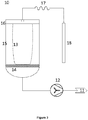
- the suction element comprises a suction pipe (18) to be inserted into the reactor via an opening, e.g. the reactor inlet (2a) or a further opening of the reactor.
- the suction pipe (18) may be connected to a flexible tube (17). Through the suction pipe (18) and the flexible tube (17), the substance, e.g. the final product, may be suck out of the reactor (2). Sucking is preferably performed under inert gas.
- the suction element (10) further comprises a glass vessel (15) connected to the flexible tube (17). More preferable, inside the glass vessel (15) is a filter bag (13), preferably a sterile or sterilized filter bag (13), connected to the flexible tube (17).
- the substance e.g. the final product, may be transferred into the bag (13) without exposing the substance to the atmosphere surrounding the reactor (2). Even more preferably, bag (13) and reactor (2) can be connected to form a closed system..
- the suction element (10) further comprises a bag holder (16) to fix the bag in the glass vessel (15) and a perforate plate (14) at the bottom of the filter bag (16).
- the suction element (10) is as shown in Figure 3 , which comprises an exhaust (11), a suction fan (12), a bag (13), a perforated plate (14), a glass vessel (15), a bag holder (16), a flexible tube (17) and a suction pipe (18).
- the substance, e.g. the final product may be transferred from the reactor into the suction element (10) under sterile conditions, preferably under aseptic conditions.
- the devices as provided by the present invention are used for preparing crystals, preferably crystals in a homogenous form, more preferably crystals which contain a crystal solvent, most preferably crystal water.
- the devices may be used in any of the methods of the present invention.
- the devices of the invention contain a stirrer (6), which is resistant to corrosion.
- the stirrer is from glass or ceramic, or from a synthetic material or plastic. More preferably, the stirrer is made of a material or at least contains a material on its surface, which is resistant against weak and strong hydrochloric acid. Examples are Hasteloy coated with PFA (Perfluoralkoxy polymer) or coated with any other Teflon based polymer or enamel coated steel.
- the geometry of the stirrer (6) is adapted to the reaction vessel. More preferably, the stirrer axis is in the centre of the reaction vessel (wherein the reaction vessel is cylindrical or almost cylindrical and the centre is the axis in the middle of the circle basis and perpendicular thereto). More preferably, the stirrer (6) leaves a low gap to the inner circumferential boundary of the side walls of the reactor (2) so that no crystal can adhere to inner boundary of the reactor (2). "Inner boundary" is another term for inner wall.
- the blade of the stirrer is elongated in the z-direction i.e. in the direction parallel to the stirrer axis.
- the stirrer (6) may be a single or double anchor stirrer.
- “Elongated" for a single anchor stirrer means that the stirrer comprises a pair of two pitched blades in an angle of 40° - 50°, preferably 45°, (opposite directions) to the stirrer axis, i.e. the z-direction, the blades elongating along the radius of the reactor.
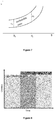
- An example of such a stirrer (6), which is a single anchor stirrer, is shown in Figure 4a (top half of Figure 4 ). On the left of Figure 4a is a view along the stirrer -axis, from the top to the bottom of the reactor (2); on the right of Figure 4a is a side view of the stirrer showing the 45° angle between each stirrer blade and z- stirrer axis.
- the preferred stirring direction is also shown in Figure 4a : the stirring direction is always opposite to the 40° - 50°, preferably 45°, angle formed by the two pitched blades respective to the stirrer axis. In Figure 4a , this is clockwise. The effect of this blade arrangement and stirring direction is obtaining a most homogeneous crystal mass.
- “Elongated" for a double anchor stirrer means that the stirrer comprises two levels of blade-arrangements. On the bottom the stirrer comprises a pair of two blades pitched in an angle of 40° - 50°, preferably 45°, (opposite directions) to the stirrer axis, i.e. the z-direction, the blades elongating along the radius of the reactor. On the second level, above the bottom, the stirrer comprises a pair of two further blades pitched in an angle to the z-axis of 40° - 50°, preferably 45°, the blades elongating along the radius of the reactor. The pair of blades of the bottom level behaves as a mirror image to the two blades on the second level.
- the support connecting the two further blades on the second level and the support connecting the two blades on bottom show an offset of 90° when viewed in the direction of the stirring axis, i.e. z-direction.
- the blades on the bottom protrude upwards from the xy plane in which the support connecting the two blades is
- the blades from the second level protrude from the xy plane in which the support connecting the two further blades is.
- the two levels of blade-pairs may overlap in z-direction as if they consists of one extended blade along the radius of the reactor.
- Figure 4b is a view along the z-axis, from the top to the bottom of the reactor (2) with the two supports connecting the two blade-pairs, perpendicular to each other, one vertical, one horizontal in the paper plane.
- the diamonds symbol the blades protruding from the paper plane upwards
- the asterices symbol the blades protruding from the paper plane downwards.
- the preferred stirring direction is in analogy to the direction shown in Figure 4a : the stirring direction is always opposite to the 40° - 50°, preferably 45°, angle formed by the respective two pitched blades respective to the stirrer axis. In Figure 4b , this is clockwise for both levels. The effect of this blade arrangement and stirring direction is obtaining a most homogeneous crystal mass.
- the reactor (2) is made from glass or at least contains glass walls.
- the glass is preferably alkali-free, more preferably a borosilicate, most preferably borosilicate 3.3.
- the material of the reactor (2) is heatable and resistant to vacuum.
- the bottom or top or side walls can be made from glass which is preferably alkali-free, more preferably a borosilicate, most preferably borosilicate 3.3; the bottom plate may be from enamel coated steel, PFA coated Hasteloy; the sealing gaskets may be made of PTFE.
- the devices of the present invention may also contain, e.g. in closed connection, one or more further collection vessels beyond the reactor (2) to separate distilled liquid and/or mother liquor without the need of opening the device to the environment. In this way, the device can be confined from the environment.
- the collection vessels may be equipped with one or more sensors, e.g. radar sensors, e.g. for continuous measurement of liquid levels.
- the devices of the present invention are used in a dust free and/or germ free and/or aseptic and/or sterile environment. For example, the device may be treated before use with water steam under over-pressure to reach a sterile environment.
- the devices are stable against oxidation, more preferably against the treatment with acids, most preferably against the treatment with strong acid.
- the device is stable against the treatment with bases, preferably with strong bases.
- Crystals which can be prepared be the methods of the invention and/or using the devices of the invention, are preferably inorganic crystals, more preferably inorganic salts.
- Typical inorganic salts are metal chlorides, metal oxides, metal halogenides, or metal pseudo-halogenides.
- Halogenides are salts from Fluorine, Bromine, Iodine, or Chlorine.
- pseudo-halogenide salts are envisaged, such as rhodamine, cyanide or the like.
- Preferred metals are manganese, chrome, copper, zinc and iron.
- Crystals contemplated are: - NiCl 2 ⁇ 6H 2 O Nickel(II)-chloride hexa-hydrate - CoCl 2 ⁇ 6H 2 O Cobalt(II) chloride hexa-hydrate - FeCl 3 ⁇ 6H 2 O Iron(III) chloride hexa-hydrate - ZnCl 2 .2/4H 2 O Zinc(II) chloride di-/ tetra-hydrate - C 12 H 22 O 14 Zn Zinc gluconate
- crystals contain selenium, such as selenite or protein containing selenium crystals.
- selenium such as selenite or protein containing selenium crystals. Examples are sodium selenite or sodium selenite pentahydrate.
- the crystals are semiconductor crystals such as crystals made of Ge, Si, ⁇ -Sn, C (Fullerene), B, Se, Te, Bi, Ca,Sr, Ba, Yb, P, S, I, GaP, GaAs, InP, InSb, InAs, GaSb, GaN, AIN, InN, Al x Ga 1-x As, In x Ga 1-x N, ZnO, ZnS, ZnSe, ZnTe, CdS, CdSe, CdTe, Hg(1-x)Cd(x)Te, BeSe, BeTe, HgS, GaS, GaSe, GaTe, InS, InSe, InTe or the like.
- semiconductor crystals such as crystals made of Ge, Si, ⁇ -Sn, C (Fullerene), B, Se, Te, Bi, Ca,Sr, Ba, Yb, P, S, I, GaP, GaAs, InP, InSb
- the crystals are pharmaceutically pure, more preferably crystals meeting the standards of the pharmacopeia, even more preferably the API standards, most preferably crystals meeting the GMP standards.
- the GMP standards can be found from the International Council for Harmonisation of Technical Requirements for Pharmaceuticals for Human Use (ICH), e.g. under https://www.ich.org/page/quality-guidelines or from the EC, e.g. under https://ec.europa.eu/health/documents/eudralex/vol-4 en
- the crystalline substance is a pharmaceutical product, preferably the one which meets the requirements of the pharmacopoeia.
- Example 1 The Concept of the Preparation of MnCl 2 ⁇ 4H 2 O crystals
- the crystallisation technique requires a defined, relatively high concentration of the MnCl 2 solution. In this concentration range the so-called metastable zone of MnCl 2 solution is situated. This zone describes a phase of the mother liquor with a defined temperature that is supersaturated - but has not yet responded with spontaneous nucleation with a certain finite time.
- Figure 5 shows the visualisation of the cooling crystallisation by highlighting the metastable zone.
- the inserted small picture gives information about the nucleation process. Shown is the schematic representation of the width of the metastable zone (thick, broad line) for the case of a cooling crystallisation along the path represented by the arrowed line (big picture).
- the system crosses the saturation line, dotted line, and becomes supersaturated. Nucleation rate becomes greater than zero.
- the exponential nature leads to near negligible nucleation rates below and a steep increase above a critical supersaturation. When the supersaturation reaches its critical value for nucleation rate to become observable, any further cooling will dramatically increase the nucleation rate, so that a macroscopically visible nucleation event occurs (small picture).
- Figure 6 shows two graphs that were recorded with the ParticleTrack sensor.
- the addition and dissolution of MnCl 2 ⁇ 4H 2 O crystals can be monitored in real time.
- addition of MnCl 2 ⁇ 4H 2 O crystals correlates to a particle counts increase of zero to > 1200 after approximately 120 seconds.
- dissolution of MnCl 2 occurs and particle counts decreased ( ⁇ 800).
- MnCl 2 ⁇ 4H 2 O was added, particle count increased, dissolution occurred and particle count decreases again.
- the particular sensor was very important to fundamentally understand the crystallisation of MnCl 2 in water. In production-scale it was not necessary to use this sensor.
- Pre-tests were conducted to investigate the metastable zone of MnCl 2 ⁇ 4H 2 O at 20 °C.
- the following procedure was conducted: A certain amount of MnCl 2 ⁇ 4H 2 O crystals were re-dissolved in water to achieve different concentrations, ranging from 20 to 55 % (m/m). The next step was to check whether the solid material was dissolved or not under stirring at 20 °C. If there was still undissolved solid MnCl 2 ⁇ 4H 2 O, that solution was heated up to 60 °C and then dissolved. Then, the solution was slowly cooled down to 20 °C and checked for crystals, see following table 1 for the results.
- Table 1 Overview of the stable, metastable and unstable zone of the MnCl 2 solution at 20 °C depending on the concentration.
- Concentration of the MnCl 2 solution % (m/m) Checking the solubility of MnCl 2 in water at 20 °C Checking the stability of a cooled down oversaturated solution to 20 °C 20 yes stable 30 32 34 36 no metastable 38 40 42 44 46 48 50 unstable 55
- Concentrations of MnCl 2 are reproduced in the left column.
- the column in the middle indicates solubility for the concentration at 20 °C.
- stability of the system is displayed (stable, metastable and unstable). Between 20 and 34 % (m/m) a stable area is obtained, that means no undissolved material was observed at 20 °C. From 34 to 36 % (m/m) a limit is reached, that states a transition into a metastable region. That metastable zone, from approximately 36 to 48 % (m/m), describes an area, where the MnCl 2 mother phase is supersaturated, but has not yet responded with spontaneous nucleation, within a certain finite time (column in the middle). Here, at 20 °C the nucleation can be induced specifically. From 48 % (m/m) upwards an unstable region prevails, where spontaneous crystallisation occurs.
- Figure 7 is a schematic representation of the metastable zone. Two distinct temperatures ⁇ 1 and ⁇ 2 are highlighted. By taking a closer look at Figure 7 , the metastable zone depends on two main reaction parameters, concentration (c) and temperature ( ⁇ ). By raising the temperature from ⁇ 1 and ⁇ 2 the whole concentration range of the metastable zone shifts upwards to higher concentration.
- concentration c
- ⁇ temperature
- the dry substance of the MnCl 2 solution after distillation shows concentrations between 49 and 52 % (m/m) (average: 51 % (m/m)).
- a small amount of hydrochloric acid (pH 0.4 and 579 ⁇ S/cm) was transferred into the distillate during the process.
- the required concentration was controlled by continuous measurement of the distillate volume. Initially, a MnCl 2 solution volume of 20 I was used. However, due to heat exchange surface and stirrer geometry of the crystalliser the volume has been increased to 26 I. Due to the relatively high temperature of the inner crystallisation reactor surface incrustation occurs at the end of the distillation process. Finally the concentrated MnCl 2 solution was heated to 70 - 80 °C under atmospheric pressure in order to remove the crust from the inner reactor surfaces and dissolution in the reactor content.
- This synthesis solution is being filtrated several times.
- a pre-filtration 0.6/0.2 ⁇ m filter
- ultrafiltration filter specification: 10 kDa
- the last filtration step is a bacterial filtration (pore size: 0.2 ⁇ m) to get a germ-free solution.
- the next processing step is purification by crystallization to eliminate other metal ions than manganese.
- the crystals are being rinsed afterwards if necessary.
- the synthesis results in a reaction solution of MnCl 2 with a concentration of 30 wt-% (m/m).
- Mn of American Elements has a purity of 99.98% based on metals basis. Manganese is in the form of pieces with size of ⁇ 13 mm. A certificate of analysis is available. The concentrated hydrochloric acid complies with Ph. Eur. ("Salzklare 37 % EMPROVE ® exp Ph. Eur., BP, JP, NF Crystal für die provoke als Exzipient").
- conductivity An important parameter that allows to track the concentration in-situ and to get us straight into the crystallization process is conductivity. As conductivity and concentration depend on each other, a certain reaction concentration can be set via conductivity, for instance to initiate the crystallization process.
- transition metal salt solutions are very acidic and corrosive
- material that is in direct contact with either the solution (reaction vessel, bag with connections, stirrer, filter paper, electrodes and all seals) or its gas phase (reaction vessel, cover plate and distillation apparatus) has to provide a chemical resistance. Potential materials have been tested and following alloy is suitable.
- Hastelloy is a well-known alloy of mainly Ni, Cr and Mo. "Hastelloy C-22" was checked for chemical resistance. A polished piece of that alloy was tested on a concentrated MnCl 2 solution (concentration: 30 wt-%). Experiment condition: One solution was kept at 20 °C (72 h) and the other was heated up to 60 °C (for 1 hour). No visual change of the surface has been detected.
- Hastelloy - except Mn - were analyzed via ICP-MS technique (see Table 2 for details). Since the medium for analysis is a highly concentrated MnCl 2 solution it is not applicable to measure the Mn assay at this point.
- Table 2 can be divided into four parts. The column on the left shows all analyzed metals. Then, from left to right following concentrations are given in ppm: Blank (MnCl 2 solution only), "Hastelloy” at different temperatures (Hastelloy in a 30 wt-% MnCl 2 solution) and the difference between Blank and "Hastelloy”. Table 2: The "Hastelloy C-22" piece was put in a 30 wt-% MnCl 2 solution and tested via ICP-MS for various metals. The blank is MnCl 2 solution without alloy.
- the blank shows very low overall concentrations with ⁇ 10 ppm.
- alloy values are comparable low with maximum 22 ppm.
- ICP-MS analysis results in a very low dissolution of metals out of the "Hastelloy C-22".
- the difference between samples with Hastelloy and blank lies only between -6 and +19 ppm. At that time, we conclude that this alloy is suitable as a material for direct contact with MnCl 2 solutions.
- the sterile process bags supplier used were from ACF (Applied Critical Fluids GmbH, manufacturer: Sartorius Stedim Biotech).
- the so called "Flexboy” bag consists of different layers (S71 film structure).
- Outer layer EVA, ethylene vinyl acetate copolymer.
- Gas barrier layer EVOH, ethyl vinyl alcohol.
- Fluid contact layer EVA, ethylene vinyl acetate copolymer.
- EVA meets the requirements of the chemical resistance of the metal salt solution.
- Figure 8 is a schematic presentation of two combined processing steps, vacuum distillation and crystallization. While distilling the amount of crystals is continuously increasing. After a certain amount of time distillation is stopped and cooling down the solution will be applied afterwards in order to maximize the yield of MnCl 2 ⁇ 4H 2 O crystals.
- the initial reaction solution with a concentration of 30% (m/m) gets concentrated and crystallization begins (darker grey area). As the amount of crystals increases over time vacuum distillation continues to an end concentration between approx. 49 and 52 wt-%. Then, the crystallization goes on at normal pressure via cooling down the reaction temperature to 5 °C.
- Ti stands for the solution temperature
- Ta for the double jacket temperature
- Tk for the temperature of the highest point in the distillation apparatus
- p for absolute pressure
- Process control parameters for distillation in production-scale are stirrer speed, pressure, temperature of the solution, temperature of the reflux condenser, temperature of the double jacket and concentration (measured via conductivity).
- Crystallization is the next processing step. This step consists of two parts. Part 1 is a continued vacuum distillation and part 2 a controlled cooling process, see Figure 8 for a schematic presentation.
- Example 1 As already stated in Example 1, after a successfully performed distillation and nucleation, the distillation must be continued in order to optimize the yield of crystals and let the volume of the residual solution be as little as possible. Afterwards, cooling of the sample will be initiated to decrease the concentration of MnCl 2 as low as possible. In both parts crystals are growing because of decreased solubility of dissolved MnCl 2 by decreasing the volume and lowering the temperature.
- Ti stands for the solution temperature
- Ta for the double jacket temperature
- p for the absolute pressure
- Process control parameters for the crystallization in production-scale are temperature of the crystal suspension, stirrer speed, duration and temperature of the double jacket.
- the end of the crystallization is preliminary set to approx. 11.6 - 14.6 wt-% rest water content (on top of 36.4 wt-% water of crystallization) which adds up to a total 49 - 52 wt-% water.
- IR balance technique percentage of water can be determined (target dry substance range: 48 - 51 %S).
- Step in lab-scale was to drain the residual mother liquor under vacuum via Nutsche filter and separate crystals from the mother liquor, which is the main purification step. Then, the residual solution was analyzed.
- Process control parameters for the crystallization in production-scale are conductivity, temperature of the solution, stirrer speed and temperature of the double jacket.
- IR balance technique determines the end of the process (target: 36.0 - 37.5 wt-% water).
- Drying wet crystals in lab-scale was achieved by heating up the double jacket (40 - 50 °C) and performing vacuum drying (approx. 30 - 100 mbar).
- stirrer speed was 30 - 140 rpm and the duration of the whole lab-scale process was 75 - 282 min.
- the planned batch size for production-scale is 11.6 kg. Preliminary total yield can be estimated to approx. 82.6 %.
- Primary packaging material is LDPE (low-density polyethylene) and secondary aluminium foil with zip lock.
- the supplier of primary (Lorafol, Losch Folien) and secondary packaging (DaklaPack) is already identified.
- Example 3 industrial scale production of MnCl 2 4 H 2 O
- a solution of MnCl 2 ⁇ 4 H 2 O is created.
- the solution is concentrated by vacuum distillation to obtain a supersaturated solution.
- the supersaturated solution shall have a concentration in the metastabile zone identified in the lab-scale experiments (see Example 2).
- the MnCl 2 solution is inserted into the reaction vessel (glass reactor) using a suction hose set.
- the distillate quantity is calculated to control the vacuum distillation.
- the nominal concentration of metastable mother liquor 50 % (m/m) is used as a basis.
- the MnCl 2 ⁇ 4 H 2 O is dissolved in hydrochloric acid.
- the solution is filtered using an ultra-filter to remove impurities.
- the distillation is carried out at a pressure of 50 mbar ("vacuum at 50 mbar") and a temperature of the double jacket surrounding the reaction vessel of 135 - 145 °C.
- the temperature of the solution is between 40 - 50 °C.
- samples may be taking via a sampling flange of the glass reactor using a sterile suction device for sampling the liquid, crystal mush (i.e. crystal cake) or crystalline samples from the glass reactor.
- a syringe may be used as well.
- a first sample may be taken during distillation from the non-saturated, saturated or supersaturated solution and/or after distillation from the obtained supersaturated solution.
- the distillation is stopped after reaching the calculated distillate quantity by breaking the vacuum.
- the deviation from the calculated value of the distillate quantity is chosen not to exceed ⁇ 1 %.
- the preparation is heated to 70 - 80 °C (jacket temperature 135 - 145 °C, no vacuum) to dissolve any precipitates that may have occurred in the reactor, in particular precipitates at the wall of the reaction vessel.
- steam might be injected to dissolve any precipitates. Steam injection was not necessary, here.
- the double jacket temperature is reduced to 1 °C.
- the pressure is set to 50 mbar. Due to the vacuum, the preparation begins to boil and is cooled down.
- the stirring speed is set to 50 RPM. Gas bubbles of the boiling solvent act as crystal seeds.
- the crystallization phase is performed by cooling the solution to 10 °C (double jacket temperature: 1°C; cooling rate: -0.3 to -2.5 °C/min).
- the solution is allowed to continue crystallizing for at least 12 hours while stirring with 25 RPM at 10 °C ( ⁇ 1 °C).
- the mother liquor is separated via the bottom valve of the reaction vessel using nitrogen overpressure (not more than 1500 mbar).
- the stirrer may be rotated briefly (25 RPM), if necessary.
- the mother liquor is removed under aeration with nitrogen.
- the change in color of the crystal cake from dark pink to light pink is monitored as an indicator of the degree of dehumidification.
- samples of the crystal cake may be taken for the determination of the loss on drying. As long as the target range (here: 41-44wt%) of the liquid in the crystal cake is not reached, nitrogen gassing of the crystal cake is continued to reach the target range.
- the ice condenser is set to -20 °C.
- the crystal cake is stirred briefly to break up the surface (max. 1 turn).
- the temperature of the double jacket (DP) is set to 1°C.
- the pressure is set from normal pressure to 5 mbar and vacuum is drawn.
- the temperature of the double jacket (DP) is set to 30 - 40 °C.
- the crystal cake is dried for 6 hours, wherein the crystal surface is broken up in approx. 2-hour intervals (1 to 4 h) by stirring briefly at 25 RPM. Stirring duration time must not be longer than 10 s per interval.
- the crystal cake is dried under these process parameters for at least 3 hours.
- the end of the dynamic drying process is marked by the reactor temperature being raised close to the double jacket temperature:
- the pressure is set to 700 mbar.
- the crystal powder is mixed well for at least 15 min at 50 RPM.
- the vacuum is broken for sampling.
- the ice condenser is defrosted and the liquid drained completely from the system.
- a sample of the crystal powder is taken for analysis purposes, e.g. drying loss is determined.
- post-drying is carried out to adjust the residual moisture of the crystal powder according to the determined drying loss.
- the glass reactor is prepared for steam injection. To do this, the condensate is drained from the steam supply and pure steam with 0.8 bar overpressure is injected into the reactor via the product line under the following conditions and parameters:
- the crystal powder is continuously stirred for at least 10 minutes (50 RPM). After performing the steam injection, perform at least one post-drying cycle needs to be performed.
- a sample of the crystal powder may be taken for analysis purposes, e.g. drying loss is determined.
- Post-drying is carried out in 30 - 60 minute cycles according to the following conditions and parameters:
- the drying loss is determined. To do this, the stirrer is switched off and the vacuum is broken.
- a sample of the crystal powder may be taken for analysis purposes, e.g. drying loss is determined.
- the production process continues by removing the final product ("powder phase") from the reaction vessel.
- a suction device is used to discharge the powder phase of the product via a connection flange of the glass reactor.
- the suction device (see Example 5) is designed like a vacuum cleaner with suction hose that is inserted into the reaction vessel. Via the suction hose, the final product is transferred into a product bag outside the reaction vessel.
- the product bag is implemented in a further glass vessel, kept under inert gas.
- the net weight of manganese(II) chloride tetra-hydrate is determined.
- the final product met the high purity standards of the API.
- Table 5 shows production parameters for producing various API grade crystalline salts.
Landscapes
- Chemical & Material Sciences (AREA)
- Crystallography & Structural Chemistry (AREA)
- Chemical Kinetics & Catalysis (AREA)
- Organic Chemistry (AREA)
- Physics & Mathematics (AREA)
- Thermal Sciences (AREA)
- Inorganic Chemistry (AREA)
- Organic Low-Molecular-Weight Compounds And Preparation Thereof (AREA)
Priority Applications (7)
| Application Number | Priority Date | Filing Date | Title |
|---|---|---|---|
| EP20180574.4A EP3925932A1 (de) | 2020-06-17 | 2020-06-17 | Geschlossene herstellung von pharmazeutisch reinen kristallen |
| US18/001,620 US20230219014A1 (en) | 2020-06-17 | 2021-06-14 | Contained production of pharmaceutically pure crystals |
| PCT/EP2021/065903 WO2021254933A1 (en) | 2020-06-17 | 2021-06-14 | Contained production of pharmaceutically pure crystals |
| IL299031A IL299031A (en) | 2020-06-17 | 2021-06-14 | Production of pharmaceutical pure crystals |
| CA3180255A CA3180255C (en) | 2020-06-17 | 2021-06-14 | Contained production of pharmaceutically pure crystals |
| EP21732288.2A EP4168360A1 (de) | 2020-06-17 | 2021-06-14 | Geschlossene herstellung von pharmazeutisch reinen kristallen |
| KR1020237001826A KR102807873B1 (ko) | 2020-06-17 | 2021-06-14 | 약학적으로 순수한 결정의 밀폐 제조 |
Applications Claiming Priority (1)
| Application Number | Priority Date | Filing Date | Title |
|---|---|---|---|
| EP20180574.4A EP3925932A1 (de) | 2020-06-17 | 2020-06-17 | Geschlossene herstellung von pharmazeutisch reinen kristallen |
Publications (1)
| Publication Number | Publication Date |
|---|---|
| EP3925932A1 true EP3925932A1 (de) | 2021-12-22 |
Family
ID=71105413
Family Applications (2)
| Application Number | Title | Priority Date | Filing Date |
|---|---|---|---|
| EP20180574.4A Withdrawn EP3925932A1 (de) | 2020-06-17 | 2020-06-17 | Geschlossene herstellung von pharmazeutisch reinen kristallen |
| EP21732288.2A Pending EP4168360A1 (de) | 2020-06-17 | 2021-06-14 | Geschlossene herstellung von pharmazeutisch reinen kristallen |
Family Applications After (1)
| Application Number | Title | Priority Date | Filing Date |
|---|---|---|---|
| EP21732288.2A Pending EP4168360A1 (de) | 2020-06-17 | 2021-06-14 | Geschlossene herstellung von pharmazeutisch reinen kristallen |
Country Status (5)
| Country | Link |
|---|---|
| US (1) | US20230219014A1 (de) |
| EP (2) | EP3925932A1 (de) |
| KR (1) | KR102807873B1 (de) |
| IL (1) | IL299031A (de) |
| WO (1) | WO2021254933A1 (de) |
Cited By (1)
| Publication number | Priority date | Publication date | Assignee | Title |
|---|---|---|---|---|
| FR3137380A1 (fr) * | 2022-07-04 | 2024-01-05 | Commissariat A L'energie Atomique Et Aux Energies Alternatives | Séparateur de sels de type à surface raclée par une plaque de raclage coulissante jusqu’à une zone de resolubilisation des sels précipités, Installation de gazéification de biomasse associée. |
Families Citing this family (1)
| Publication number | Priority date | Publication date | Assignee | Title |
|---|---|---|---|---|
| CN119666838B (zh) * | 2024-12-11 | 2025-12-26 | 中国石油化工股份有限公司 | 一种图像法辅助电导率法在线监测高含杂、低透光率结晶体系结晶介稳区的方法及系统 |
Citations (3)
| Publication number | Priority date | Publication date | Assignee | Title |
|---|---|---|---|---|
| US2067043A (en) * | 1933-10-25 | 1937-01-05 | Swenson Evaporator Company | Vacuum crystallizer and method of crystallizing |
| DE60310923T2 (de) | 2002-05-31 | 2007-07-05 | Accentus Plc | Herstellung von kristallmaterialien mittels hochleistungsultraschall |
| CN104274994A (zh) * | 2013-07-01 | 2015-01-14 | 天津长芦汉沽盐场有限责任公司 | 晶体氯化镁连续结晶的生产方法 |
Family Cites Families (4)
| Publication number | Priority date | Publication date | Assignee | Title |
|---|---|---|---|---|
| IL196658A (en) | 2009-01-22 | 2013-11-28 | Ide Technologies Ltd | A system and method for making brine solids |
| CA2739048A1 (en) * | 2011-05-03 | 2012-11-03 | Cpg Resources-Mineral Technologies Pty Ltd | A slurry and wash liquid distributor |
| KR101767715B1 (ko) * | 2014-12-22 | 2017-08-24 | 주식회사 포스코 | 배소 장치 및 염화철 배소 방법 |
| SG11201800183YA (en) * | 2015-07-08 | 2018-02-27 | Daewoo Shipbuilding & Marine | Ship comprising engine |
-
2020
- 2020-06-17 EP EP20180574.4A patent/EP3925932A1/de not_active Withdrawn
-
2021
- 2021-06-14 EP EP21732288.2A patent/EP4168360A1/de active Pending
- 2021-06-14 US US18/001,620 patent/US20230219014A1/en active Pending
- 2021-06-14 IL IL299031A patent/IL299031A/en unknown
- 2021-06-14 KR KR1020237001826A patent/KR102807873B1/ko active Active
- 2021-06-14 WO PCT/EP2021/065903 patent/WO2021254933A1/en not_active Ceased
Patent Citations (3)
| Publication number | Priority date | Publication date | Assignee | Title |
|---|---|---|---|---|
| US2067043A (en) * | 1933-10-25 | 1937-01-05 | Swenson Evaporator Company | Vacuum crystallizer and method of crystallizing |
| DE60310923T2 (de) | 2002-05-31 | 2007-07-05 | Accentus Plc | Herstellung von kristallmaterialien mittels hochleistungsultraschall |
| CN104274994A (zh) * | 2013-07-01 | 2015-01-14 | 天津长芦汉沽盐场有限责任公司 | 晶体氯化镁连续结晶的生产方法 |
Non-Patent Citations (4)
| Title |
|---|
| "Crystallization: Basic Concepts and Industrial Applications", 28 February 2013, WILEY-VCH VERLAG GMBH & CO. KGAA., ISBN: 978-3-527-32762-1, article GÜNTER HOFMANN ET AL: "1 Continuous Crystallization", pages: 203 - 233, XP055753776, DOI: 10.1002/9783527650323 * |
| ANONYMOUS ET AL: "Certificate of Analysis Manganese Chloride", 1 January 2020 (2020-01-01), pages 1, XP055753813, Retrieved from the Internet <URL:https://www.nanoshel.com/admin/DownloadPDF/download/2231/COA> [retrieved on 20201125] * |
| G. E SEAVOY ET AL: "VACUUM AND MECHANICAL CRYSTALLIZERS A COMPARISON", INDUSTRIAL AND ENGINEERING CHEMISTRY, 1 May 1940 (1940-05-01), pages 627 - 636, XP055753773, Retrieved from the Internet <URL:https://pubs.acs.org/doi/pdfplus/10.1021/ie50365a010> DOI: 10.1021/ie50365a010 * |
| W. BECKMANN: "crystallization - Basic Concepts and Industrial Applications", 2013, WILEY-VCH |
Cited By (2)
| Publication number | Priority date | Publication date | Assignee | Title |
|---|---|---|---|---|
| FR3137380A1 (fr) * | 2022-07-04 | 2024-01-05 | Commissariat A L'energie Atomique Et Aux Energies Alternatives | Séparateur de sels de type à surface raclée par une plaque de raclage coulissante jusqu’à une zone de resolubilisation des sels précipités, Installation de gazéification de biomasse associée. |
| WO2024008708A1 (fr) * | 2022-07-04 | 2024-01-11 | Commissariat A L'energie Atomique Et Aux Energies Alternatives | Séparateur de sels de type à surface raclée par une plaque de raclage coulissante jusqu'à une zone de resolubilisation des sels précipités, installation de gazéification de biomasse associée. |
Also Published As
| Publication number | Publication date |
|---|---|
| EP4168360A1 (de) | 2023-04-26 |
| KR102807873B1 (ko) | 2025-05-14 |
| IL299031A (en) | 2023-02-01 |
| WO2021254933A1 (en) | 2021-12-23 |
| US20230219014A1 (en) | 2023-07-13 |
| CA3180255A1 (en) | 2021-12-23 |
| KR20230025006A (ko) | 2023-02-21 |
Similar Documents
| Publication | Publication Date | Title |
|---|---|---|
| Yang et al. | Selective crystallisation of carbamazepine polymorphs on surfaces with differing properties | |
| US20230219014A1 (en) | Contained production of pharmaceutically pure crystals | |
| WO2008134936A1 (en) | Method for extracting threonine from threonine fermentation liquor | |
| US20040005255A1 (en) | Appartus and process used in growing crystals | |
| Curcio et al. | Membrane crystallization of macromolecular solutions | |
| CA3180255C (en) | Contained production of pharmaceutically pure crystals | |
| WO2016207056A1 (en) | Semi-continuous crystallization method and apparatus | |
| Pawar et al. | Crystallization of erythromycin extracted using novel phase separation ‘sugaring-out extraction’: A combined modelling and experimental approach | |
| CN104903236B (zh) | 生产硫酸铵晶体的方法和装置 | |
| EP0654291B1 (de) | Verfahren zur Kristallisierung organischer Chemikalien | |
| CN113200810A (zh) | 一种番茄红素晶体及番茄红素结晶工艺 | |
| SA07270506B1 (ar) | طريقة لإنتاج حمض الاكريليك | |
| KR101463186B1 (ko) | 약학적으로 순수한 결정을 제조하는 방법 | |
| WO2004037759A1 (ja) | 改善された連続晶析方法 | |
| CN102190702A (zh) | 提高蛋白质结晶率的方法 | |
| US12240801B2 (en) | Method of synthesis and purification of citrulline | |
| RU2182148C2 (ru) | Способ очистки ди(с1-с6)алкилового сложного эфира (6-хлор-2-карбазолил)метилмалоновой кислоты | |
| JP4731980B2 (ja) | ステロール類の晶析方法およびそのシステム | |
| JP2610638B2 (ja) | 単結晶の製造方法 | |
| JP2006281193A (ja) | 液−液界面を利用する結晶析出方法及び新規な結晶体 | |
| US20080092340A1 (en) | Method For The Preparation Of Precipitates | |
| Yamano | Development of new drug and crystal polymorphs | |
| MYERSON et al. | The Agglomeration and Aging of Terephthalic Acid Particles in Liquid Solution | |
| JP5594670B2 (ja) | 液−液界面を利用する被覆型複合物質の製造方法 | |
| WO2026105044A1 (en) | A process for the cold stabilisation of wine |
Legal Events
| Date | Code | Title | Description |
|---|---|---|---|
| PUAI | Public reference made under article 153(3) epc to a published international application that has entered the european phase |
Free format text: ORIGINAL CODE: 0009012 |
|
| STAA | Information on the status of an ep patent application or granted ep patent |
Free format text: STATUS: THE APPLICATION HAS BEEN PUBLISHED |
|
| AK | Designated contracting states |
Kind code of ref document: A1 Designated state(s): AL AT BE BG CH CY CZ DE DK EE ES FI FR GB GR HR HU IE IS IT LI LT LU LV MC MK MT NL NO PL PT RO RS SE SI SK SM TR |
|
| B565 | Issuance of search results under rule 164(2) epc |
Effective date: 20201203 |
|
| STAA | Information on the status of an ep patent application or granted ep patent |
Free format text: STATUS: THE APPLICATION IS DEEMED TO BE WITHDRAWN |
|
| 18D | Application deemed to be withdrawn |
Effective date: 20220623 |