EP3926162A1 - Procédé de fonctionnement d'une éolienne, dispositif de commande destiné au fonctionnement d'un éolienne et parc éolien - Google Patents
Procédé de fonctionnement d'une éolienne, dispositif de commande destiné au fonctionnement d'un éolienne et parc éolien Download PDFInfo
- Publication number
- EP3926162A1 EP3926162A1 EP21177034.2A EP21177034A EP3926162A1 EP 3926162 A1 EP3926162 A1 EP 3926162A1 EP 21177034 A EP21177034 A EP 21177034A EP 3926162 A1 EP3926162 A1 EP 3926162A1
- Authority
- EP
- European Patent Office
- Prior art keywords
- pitch
- wind
- wind energy
- pitch angle
- energy installation
- Prior art date
- Legal status (The legal status is an assumption and is not a legal conclusion. Google has not performed a legal analysis and makes no representation as to the accuracy of the status listed.)
- Granted
Links
Images




Classifications
-
- F—MECHANICAL ENGINEERING; LIGHTING; HEATING; WEAPONS; BLASTING
- F03—MACHINES OR ENGINES FOR LIQUIDS; WIND, SPRING, OR WEIGHT MOTORS; PRODUCING MECHANICAL POWER OR A REACTIVE PROPULSIVE THRUST, NOT OTHERWISE PROVIDED FOR
- F03D—WIND MOTORS
- F03D7/00—Controlling wind motors
- F03D7/02—Controlling wind motors the wind motors having rotation axis substantially parallel to the air flow entering the rotor
- F03D7/022—Adjusting aerodynamic properties of the blades
- F03D7/0224—Adjusting blade pitch
-
- F—MECHANICAL ENGINEERING; LIGHTING; HEATING; WEAPONS; BLASTING
- F03—MACHINES OR ENGINES FOR LIQUIDS; WIND, SPRING, OR WEIGHT MOTORS; PRODUCING MECHANICAL POWER OR A REACTIVE PROPULSIVE THRUST, NOT OTHERWISE PROVIDED FOR
- F03D—WIND MOTORS
- F03D1/00—Wind motors with rotation axis substantially parallel to the air flow entering the rotor
- F03D1/06—Rotors
- F03D1/0608—Rotors characterised by their aerodynamic shape
- F03D1/0633—Rotors characterised by their aerodynamic shape of the blades
-
- F—MECHANICAL ENGINEERING; LIGHTING; HEATING; WEAPONS; BLASTING
- F03—MACHINES OR ENGINES FOR LIQUIDS; WIND, SPRING, OR WEIGHT MOTORS; PRODUCING MECHANICAL POWER OR A REACTIVE PROPULSIVE THRUST, NOT OTHERWISE PROVIDED FOR
- F03D—WIND MOTORS
- F03D1/00—Wind motors with rotation axis substantially parallel to the air flow entering the rotor
- F03D1/06—Rotors
- F03D1/065—Rotors characterised by their construction elements
- F03D1/0675—Rotors characterised by their construction elements of the blades
-
- F—MECHANICAL ENGINEERING; LIGHTING; HEATING; WEAPONS; BLASTING
- F03—MACHINES OR ENGINES FOR LIQUIDS; WIND, SPRING, OR WEIGHT MOTORS; PRODUCING MECHANICAL POWER OR A REACTIVE PROPULSIVE THRUST, NOT OTHERWISE PROVIDED FOR
- F03D—WIND MOTORS
- F03D17/00—Monitoring or testing of wind motors, e.g. diagnostics
-
- F—MECHANICAL ENGINEERING; LIGHTING; HEATING; WEAPONS; BLASTING
- F03—MACHINES OR ENGINES FOR LIQUIDS; WIND, SPRING, OR WEIGHT MOTORS; PRODUCING MECHANICAL POWER OR A REACTIVE PROPULSIVE THRUST, NOT OTHERWISE PROVIDED FOR
- F03D—WIND MOTORS
- F03D7/00—Controlling wind motors
- F03D7/02—Controlling wind motors the wind motors having rotation axis substantially parallel to the air flow entering the rotor
- F03D7/022—Adjusting aerodynamic properties of the blades
- F03D7/0236—Adjusting aerodynamic properties of the blades by changing the active surface of the wind engaging parts, e.g. reefing or furling
-
- F—MECHANICAL ENGINEERING; LIGHTING; HEATING; WEAPONS; BLASTING
- F03—MACHINES OR ENGINES FOR LIQUIDS; WIND, SPRING, OR WEIGHT MOTORS; PRODUCING MECHANICAL POWER OR A REACTIVE PROPULSIVE THRUST, NOT OTHERWISE PROVIDED FOR
- F03D—WIND MOTORS
- F03D7/00—Controlling wind motors
- F03D7/02—Controlling wind motors the wind motors having rotation axis substantially parallel to the air flow entering the rotor
- F03D7/04—Automatic control; Regulation
- F03D7/042—Automatic control; Regulation by means of an electrical or electronic controller
- F03D7/048—Automatic control; Regulation by means of an electrical or electronic controller controlling wind farms
-
- F—MECHANICAL ENGINEERING; LIGHTING; HEATING; WEAPONS; BLASTING
- F03—MACHINES OR ENGINES FOR LIQUIDS; WIND, SPRING, OR WEIGHT MOTORS; PRODUCING MECHANICAL POWER OR A REACTIVE PROPULSIVE THRUST, NOT OTHERWISE PROVIDED FOR
- F03D—WIND MOTORS
- F03D80/00—Details, components or accessories not provided for in groups F03D1/00 - F03D17/00
-
- F—MECHANICAL ENGINEERING; LIGHTING; HEATING; WEAPONS; BLASTING
- F03—MACHINES OR ENGINES FOR LIQUIDS; WIND, SPRING, OR WEIGHT MOTORS; PRODUCING MECHANICAL POWER OR A REACTIVE PROPULSIVE THRUST, NOT OTHERWISE PROVIDED FOR
- F03D—WIND MOTORS
- F03D9/00—Adaptations of wind motors for special use; Combinations of wind motors with apparatus driven thereby; Wind motors specially adapted for installation in particular locations
- F03D9/20—Wind motors characterised by the driven apparatus
- F03D9/25—Wind motors characterised by the driven apparatus the apparatus being an electrical generator
-
- F—MECHANICAL ENGINEERING; LIGHTING; HEATING; WEAPONS; BLASTING
- F05—INDEXING SCHEMES RELATING TO ENGINES OR PUMPS IN VARIOUS SUBCLASSES OF CLASSES F01-F04
- F05B—INDEXING SCHEME RELATING TO WIND, SPRING, WEIGHT, INERTIA OR LIKE MOTORS, TO MACHINES OR ENGINES FOR LIQUIDS COVERED BY SUBCLASSES F03B, F03D AND F03G
- F05B2270/00—Control
- F05B2270/10—Purpose of the control system
- F05B2270/20—Purpose of the control system to optimise the performance of a machine
- F05B2270/204—Purpose of the control system to optimise the performance of a machine taking into account the wake effect
-
- F—MECHANICAL ENGINEERING; LIGHTING; HEATING; WEAPONS; BLASTING
- F05—INDEXING SCHEMES RELATING TO ENGINES OR PUMPS IN VARIOUS SUBCLASSES OF CLASSES F01-F04
- F05B—INDEXING SCHEME RELATING TO WIND, SPRING, WEIGHT, INERTIA OR LIKE MOTORS, TO MACHINES OR ENGINES FOR LIQUIDS COVERED BY SUBCLASSES F03B, F03D AND F03G
- F05B2270/00—Control
- F05B2270/30—Control parameters, e.g. input parameters
- F05B2270/32—Wind speeds
-
- F—MECHANICAL ENGINEERING; LIGHTING; HEATING; WEAPONS; BLASTING
- F05—INDEXING SCHEMES RELATING TO ENGINES OR PUMPS IN VARIOUS SUBCLASSES OF CLASSES F01-F04
- F05B—INDEXING SCHEME RELATING TO WIND, SPRING, WEIGHT, INERTIA OR LIKE MOTORS, TO MACHINES OR ENGINES FOR LIQUIDS COVERED BY SUBCLASSES F03B, F03D AND F03G
- F05B2270/00—Control
- F05B2270/30—Control parameters, e.g. input parameters
- F05B2270/328—Blade pitch angle
-
- F—MECHANICAL ENGINEERING; LIGHTING; HEATING; WEAPONS; BLASTING
- F05—INDEXING SCHEMES RELATING TO ENGINES OR PUMPS IN VARIOUS SUBCLASSES OF CLASSES F01-F04
- F05B—INDEXING SCHEME RELATING TO WIND, SPRING, WEIGHT, INERTIA OR LIKE MOTORS, TO MACHINES OR ENGINES FOR LIQUIDS COVERED BY SUBCLASSES F03B, F03D AND F03G
- F05B2270/00—Control
- F05B2270/30—Control parameters, e.g. input parameters
- F05B2270/337—Electrical grid status parameters, e.g. voltage, frequency or power demand
-
- F—MECHANICAL ENGINEERING; LIGHTING; HEATING; WEAPONS; BLASTING
- F05—INDEXING SCHEMES RELATING TO ENGINES OR PUMPS IN VARIOUS SUBCLASSES OF CLASSES F01-F04
- F05B—INDEXING SCHEME RELATING TO WIND, SPRING, WEIGHT, INERTIA OR LIKE MOTORS, TO MACHINES OR ENGINES FOR LIQUIDS COVERED BY SUBCLASSES F03B, F03D AND F03G
- F05B2270/00—Control
- F05B2270/40—Type of control system
- F05B2270/404—Type of control system active, predictive, or anticipative
-
- Y—GENERAL TAGGING OF NEW TECHNOLOGICAL DEVELOPMENTS; GENERAL TAGGING OF CROSS-SECTIONAL TECHNOLOGIES SPANNING OVER SEVERAL SECTIONS OF THE IPC; TECHNICAL SUBJECTS COVERED BY FORMER USPC CROSS-REFERENCE ART COLLECTIONS [XRACs] AND DIGESTS
- Y02—TECHNOLOGIES OR APPLICATIONS FOR MITIGATION OR ADAPTATION AGAINST CLIMATE CHANGE
- Y02E—REDUCTION OF GREENHOUSE GAS [GHG] EMISSIONS, RELATED TO ENERGY GENERATION, TRANSMISSION OR DISTRIBUTION
- Y02E10/00—Energy generation through renewable energy sources
- Y02E10/70—Wind energy
- Y02E10/72—Wind turbines with rotation axis in wind direction
Definitions
- the invention relates to a method for operating a wind turbine in the wake of which there is a second wind turbine in at least one wake wind direction, a control device for operating a wind turbine and a wind park with a first wind turbine and a second wind turbine.
- Wind turbines are known in principle, they generate electrical power from wind.
- Wind energy plants generally relate to horizontal-axis wind energy plants in which the rotor axis is aligned essentially horizontally and the rotor blades sweep over an essentially vertical rotor surface.
- wind energy installations generally comprise a tower on which the nacelle with the rotor is arranged such that it can rotate about an essentially vertically oriented axis.
- the rotor usually comprises three rotor blades.
- the rotor blades are slim components that are often made of fiber-reinforced plastic.
- wind power plants are usually not set up singularly, but rather in conjunction with at least one further wind power plant, in particular with a large number of wind power plants.
- Such a collection of wind turbines is also referred to as a wind park.
- Wind turbines in a wind farm can influence each other. This is the case, for example, when a wind energy installation is aerodynamically shaded by another wind energy installation.
- Aerodynamic shading occurs when the wind energy installation located leeward is in the slipstream of the wind energy installation located upwind.
- a slipstream is also known as a wake or wake.
- a wind energy installation that is in the wake usually does not provide the usual output for a specific wind speed. It often also happens that the wind energy installation in the overrun does not or cannot achieve its nominal output or does not reach it until later in relation to an undisturbed wind speed.
- the output of the wind farm is therefore to be determined taking into account the individual output of the wind energy plants, with lag effects to be taken into account. Because of this, the goal is usually not to optimize the individual wind energy installations individually with regard to their performance, but rather to optimize the wind farm as such.
- the underlying optimization problem should therefore primarily maximize the performance of the wind farm.
- the aforementioned object is achieved by a method for operating a first wind turbine with a rotor which has a rotor blade that can be adjusted with a pitch angle, generates electrical power and in the wake of which there is a second wind turbine in at least one wake wind direction, comprising the step of: operating the first wind turbine in an essentially lag-free normal mode with a first pitch characteristic and operating the first wind turbine in a lag-loaded lag operation with a second pitch characteristic, the first pitch characteristic having a first pitch angle and the second pitch characteristic having a second pitch angle as a function of the electrical power, the pitch angle of the second pitch characteristic curve being greater than the pitch angle of the first pitch characteristic curve for at least one area of the electrical power.
- the second wind energy installation is located in the wake of the first wind energy installation when the wind is blowing from the at least one wake wind direction.
- the wake wind direction is preferably defined as a wind direction range, for example a wind direction range that includes approximately 15 degrees, it being possible for this to depend on the model used.
- the lag is characterized in particular by the fact that the second wind energy installation is aerodynamically influenced, in particular shaded, by the first wind energy installation.
- the second wind energy installation is therefore located in the wake of the first wind energy installation when the wind is blowing from the at least one wake wind direction. If the second wind energy installation is in the wake of the first wind energy installation, the aerodynamic conditions at the second wind energy installation are changed compared to a flow situation that is not influenced by the first wind energy installation. If the second wind energy installation is essentially not in the wake of the first wind energy installation, this state is referred to as no overrun. If the second wind energy installation is in the wake of the first wind energy installation, this state is referred to as overrun.
- the first wind energy installation is operated in the essentially idle normal operation with a first pitch characteristic. If the second wind energy installation is under load, that is to say it is in the wake of the first wind energy installation, the first wind energy installation is operated in overrun mode with a second pitch characteristic.
- the first pitch characteristic represents a first course of the pitch angle as a function of the electrical power.
- the pitch characteristic curve preferably includes a defined pitch angle for each value of the electrical power.
- the second pitch characteristic represents a second course of the pitch angle as a function of the electrical power.
- the second pitch characteristic thus assigns a defined pitch angle to each electrical power, analogously to the first pitch characteristic. This assignment is preferably established for a defined range of electrical power, in particular for each electrical power that can arise during operation of the wind energy installation, for example between 0 kW and the nominal power.
- the first pitch characteristic curve and the second pitch characteristic curve essentially match up to a first power threshold value of the electrical power, and for an electrical power exceeding the first power threshold value, the pitch angle of the second pitch characteristic curve is greater than the pitch angle of the first pitch characteristic curve.
- the first pitch characteristic curve and the second pitch characteristic curve accordingly preferably essentially coincide up to a first power threshold value of the electrical power.
- Matching means in particular that the pitch angle of the first pitch characteristic curve and the pitch angle of the second pitch characteristic curve are essentially the same for essentially any electrical power below the power threshold value.
- the first pitch characteristic curve and the second pitch characteristic curve can also be different from one another in all areas.
- the pitch angle deviates from one another by less than 30%, less than 20% or less than 10% of the first and second pitch characteristics for a defined electrical power.
- the pitch angle is significantly increased across the board in the overrun-loaded operation in order to reduce the turbulence-induced loads.
- the collective pitch angle is set to 5 °, 6 ° or 6.5 ° and / or increased by more than 2 °, 3 ° or 4 °.
- the pitch angle of the second pitch characteristic is greater than the pitch angle of the first pitch characteristic. This means that for a specific electrical power that is greater than the first power threshold value, the pitch angle in the overrun-loaded follow-up operation is greater than the pitch angle to be set in the follow-up-free normal operation. If, for example, the second wind energy installation is essentially not subject to overrun load, the first wind energy installation is operated with the first pitch characteristic.
- a pitch angle of 2 ° can be set with a power of 1500 kW, this naturally depending on the nominal power of the wind energy installation and other design parameters.
- the first wind energy installation becomes with the second Pitch characteristic operated.
- a pitch angle of approximately 4 ° would be set for the same exemplary wind energy installation, for example with a power of 1500 kW. It can be seen from this that in the case of electrical power which exceeds the first power threshold value, the pitch angle of the second pitch characteristic is greater than the pitch angle of the first pitch characteristic.
- a preferred embodiment of the method provides that for an electrical power that is smaller than the first power threshold value, the pitch angle of the first pitch characteristic and the pitch angle of the second pitch characteristic are essentially the same, and / or wherein the course of the first pitch characteristic and / or the course of the second pitch characteristic curve has essentially no slope until the first power threshold value is exceeded.
- the first pitch characteristic defines a pitch angle of 2 ° for an electrical power of 500 kW in the area below the first power threshold value.
- the second pitch characteristic would also have a pitch angle of 2 ° in the area below the first power threshold value for an electrical power of 500 kW.
- a course of the first pitch characteristic without an increase is characterized in particular by the fact that the pitch angle remains essentially constant even with increasing electrical power.
- the pitch angle can be 2 °.
- the same essentially applies to the second collective pitch characteristic.
- the first and / or the second wind energy installation has a wind speed-dependent maximum permissible thrust coefficient
- the The pitch angle of the second pitch characteristic curve has such a profile that a thrust coefficient occurring at the wind energy installation does not substantially exceed the maximum permissible thrust coefficient.
- This maximum thrust coefficient can originate, for example, from a turbulence intensity that is subject to trailing loads.
- the second collective pitch curve has a course that the thrust coefficient exerted by the wind turbine located upwind does not exceed a maximum thrust coefficient that stems from a limitation of the turbulence intensity of a wind turbine that is on the leeward side and is therefore loaded with lag.
- the second wind energy installation has a maximum permissible turbulence intensity that is dependent on the wind speed, the pitch angle of the second pitch characteristic curve having a course such that a turbulence intensity occurring at the wind energy installation does not substantially exceed the maximum permissible turbulence intensity.
- TI Max TI WK ⁇ 0 , 75 ⁇ v + 5 , 6th v .
- TI WK depends on the wind class, which is divided into classes A, B and C.
- TI WK can be 0.12, 0.14, and 0.16.
- the speed v is to be calculated using lag models, for example those from Jensen, Qian, Porte-Agel.
- These follow-up models usually require the thrust coefficient of the windward turbine, which can be calculated, for example, with the help of a Blade Element Momentum Theory (BEM). Therefore, as a boundary condition for maximizing the electrical power of the wind farm, it is usually established that the turbulence applied to the wind energy installation subject to lag is less than a maximum permissible turbulence TI max .
- the invention is based, inter alia, on the knowledge that this turbulence-related secondary condition is equivalent to the fact that the thrust coefficient of a wind energy installation subject to lag is lower than a maximum permissible thrust coefficient.
- further variables are to be used for the evaluation, for example the high speed number can be included in the inequality.
- a preferred development of the method is characterized in that for an electrical power exceeding the first power threshold value, which is smaller than a second power threshold value, the pitch angle of the first pitch characteristic curve is essentially constant and the pitch angle of the second pitch characteristic curve rises, preferably steadily, especially preferably increases linearly, although other courses are also possible.
- the pitch angle of the first pitch characteristic curve is therefore essentially constant between the first power threshold value and the second power threshold value, regardless of the electrical power. Between the first power threshold value and the second power threshold value, the pitch angle of the second pitch characteristic curve increases with increasing electrical power.
- the first pitch characteristic curve has a positive slope, which is preferably less than the slope of the second pitch characteristic curve.
- the second pitch characteristic curve preferably has a first constant section of the pitch angle below the first power threshold value, a rising section between the first power threshold value and the third power threshold value, and again a constant section from the third power threshold value, with other curves also being advantageous.
- the pitch angle of the second pitch characteristic curve is essentially constant, and preferably a value between 4 ° -8 °, in particular between 6 ° -7 °, assumes.
- the first power threshold value is between 70% to 80% of the nominal power of the first wind energy installation.
- Power threshold values can in particular be recognized by a kink in the pitch angle power characteristic.
- the object mentioned at the beginning is achieved by a control device for operating a first wind energy installation with a rotor which has a rotor blade which is adjustable with a pitch angle and which has electrical power generated and in the wake of which there is a second wind energy installation with at least one wake wind direction, the control device being set up to operate the first wind energy installation in an essentially wake-free normal mode with a first pitch characteristic and in a wake-loaded wake with a second pitch characteristic, the first pitch characteristic a first course of the pitch angle and the second pitch characteristic represents a second course of the pitch angle as a function of the electrical power, the pitch angle of the second pitch characteristic being greater than the pitch angle of the first pitch characteristic for at least one range of the electrical power.
- the above-mentioned object is achieved by a wind park with a first wind energy installation with a rotor which has a rotor blade which can be adjusted with a pitch angle, generates electrical power and in the wake of which there is a second wind energy installation in at least one wake wind direction, wherein the wind farm is designed to carry out a method according to one of the embodiment variants mentioned above, and / or comprises a control device according to the previous aspect.
- FIG. 1 shows a schematic representation of a wind energy installation 100.
- the wind energy installation 100 has a tower 102 and a nacelle 104 on the tower 102.
- An aerodynamic rotor 106 with three rotor blades 108 and a spinner 110 is provided on the nacelle 104.
- the aerodynamic rotor 106 is set in rotation by the wind during operation of the wind energy installation and thus also rotates an electrodynamic rotor or rotor of a generator, which is coupled directly or indirectly to the aerodynamic rotor 106.
- the electrical generator is arranged in the nacelle 104 and generates electrical energy.
- the pitch angles 114 of the rotor blades 108 can be changed by pitch drives 116 at the rotor blade roots of the respective rotor blades 108.
- the wind energy installation 100 further comprises a control device 118 which is set up to operate the wind energy installation 100 in an essentially coasting-free normal mode with a first pitch characteristic and in a coasting-loaded coasting operation with a second pitch characteristic.
- the first pitch characteristic represents a first course of the pitch angle and the second pitch characteristic represents a second course of the pitch angle as a function of the electrical power.
- the first pitch characteristic curve and the second pitch characteristic curve essentially match up to a first power threshold value of the electrical power. For electrical power that exceeds the first power threshold, the pitch angle of the second pitch characteristic is greater than the pitch angle of the first pitch characteristic.
- FIG. 11 shows a schematic view of an exemplary embodiment of a wind farm 112.
- Figure 2 shows the wind park 112 with, by way of example, three wind energy installations 100a, 100b, 100c.
- the three wind turbines 100a, 100b, 100c represent basically any number of wind turbines of the wind park 112.
- the wind turbines 100a, 100b, 100c provide their electrical power, namely in particular the generated electricity, via an electrical park network 114.
- the currents or powers generated in each case by the individual wind turbines 100a, 100b, 100c are added up and a transformer 116 is usually provided, which steps up the voltage in the park in order to be supplied to the feed point 118, which is also generally known as PCC is designated to feed into the supply network 120.
- Figure 2 is only a simplified representation of a wind park 112.
- the park network 114 can be designed differently in that, for example, a transformer is also present at the output of each wind energy installation 100a, 100b, 100c.
- the wind energy installation 100b When the wind direction W is drawn in, the wind energy installation 100b is located in the wake of the wind energy installation 100a.
- the wind energy installation 100a is arranged in windward direction of the wind energy installation 100b.
- the wind energy installation 100a is preferably operated, at least at times, in an overrun-loaded overrun operation, in which the wind energy installation 100b is located in the overrun of the wind energy installation 100a. This means in particular that a second pitch characteristic is provided for this operation.
- the wind energy installation 100c In the wind direction W, the wind energy installation 100c is likewise located in the wake of the wind energy installations 100a and 100b.
- the wind energy installation 100a will hereinafter also be referred to as the first wind energy installation 100a and the wind energy installation 100b as the second wind energy installation 100b.
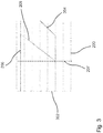
- FIG 3 shows schematic courses of pitch characteristics.
- the electrical power 200 of the foremost wind energy installation that is to say the wind energy installation that is not in the wake, is plotted on the abscissa.
- a pitch angle 202 of the wind energy installation 100a is plotted on the ordinate.
- the first pitch characteristic is used for the wind energy installation 100a when it is in normal operation without overrun, i.e., depending on the wind direction, there is no wind energy installation of the wind energy installations 100b, 100c in the overrun of the wind energy installation 100a.
- the first wind energy installation 100a is in the normal operation without lag, in particular when the wind is blowing from a wind direction that is different from that in FIG Figure 2 shown wind direction W.
- a conventional pitch characteristic curve 206 is provided for an after-run operation with a load on the run-on.
- This conventional pitch characteristic curve 206 provides that, as soon as a wind power installation is in the wake of another wind power installation, the pitch angle is set to a higher value across the board in order to reduce the thrust coefficients.
- Figure 4 shows a course an undisturbed wind speed 210 is plotted on the ordinate, for example in meters per second, over a thrust coefficient 212 on the abscissa for various pitch angle profiles Fig. 4 , which is described in more detail below, the pitch angle profiles shown below represent such profiles for higher pitch angles. It will be in the Figure 4 In particular, it can be seen that the larger the pitch angle, the smaller the thrust coefficient.
- the second pitch characteristic curve 208 is shown, which essentially corresponds to a first pitch characteristic curve 204 up to a first power threshold value 207 of the electrical power 200.
- the pitch angle 202 of the second pitch characteristic curve 208 is greater than the pitch angle 202 of the first pitch characteristic curve 204.
- the first pitch characteristic curve 204 can be, for example, a typical pitch characteristic curve, which in any case specifies increasing pitch angles from the achievement of the nominal power. In other cases, however, both the first pitch characteristic curve 204 and the second pitch characteristic curve 208 can provide, for example, an increase in the pitch angle in the partial load range. For example, a linear increase can be provided until the nominal power is reached and a non-linear increase from the reaching of the nominal power.
- the second pitch characteristic with which the first wind energy installation 100a is operated results in the after-run operation of the wind energy installation 100b with overrun load, so that a high electrical power can be generated in the partial load range below the first power threshold value 207, since here the thrust values are usually low or here higher thrust coefficients allowed are.
- the pitch angle of the second pitch characteristic curve 208 is increased in order to reduce the thrust coefficients. In this way, for example, a thrust reserve that is still present, that is to say up to the maximum permissible loads, of the wind energy installation 100b which is in the lagging position can be used, which in turn increases the yield of the wind energy installation 100b.
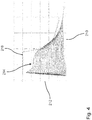
- FIG 4 shows schematic progressions of shear coefficients.
- the wind speed 210 is plotted on the abscissa, for example in meters per second.
- the shear coefficient 212 is plotted on the ordinate.
- the course of the maximum permissible thrust coefficient 216 is also plotted.
- the maximum thrust coefficient 216 is always greater than it is for certain pitch values. This means that almost any pitch angle can be set in this low wind speed range, regardless of a maximum permissible thrust coefficient, so that the focus can be almost exclusively on generating maximum electrical power.
- a thrust coefficient set by a pitch angle that would be optimal for performance can exceed the maximum thrust coefficient 216. In this case, the pitch angle must be adjusted accordingly so that the resulting thrust coefficient does not essentially exceed the maximum thrust coefficient.
- Figure 5 shows selected courses of shear coefficients Figure 4 .
- the wind speed is plotted on the abscissa, for example in meters per second, and the thrust coefficient 222 is plotted on the ordinate.
- the thrust coefficient curve 228 represents the thrust coefficient by way of example for a pitch angle that of the pitch characteristic curve 206 of FIG Fig. 3 is equivalent to.
- the thrust coefficient curve 224 for the second collective pitch characteristic curve 208 shows that a higher thrust coefficient is always achieved in the partial load range. This usually results in the generation of higher electrical power.
- the thrust coefficient curve 224 for the second collective pitch characteristic curve 208 is closer to the curve of the maximum permissible thrust coefficient 226, especially in the partial load range.
- FIG. 6 shows a schematic process.
- a first wind energy installation 100a and a second wind energy installation 100b are each operated in normal operation with no lag with the first pitch characteristic curve 204.
- none of the wind energy installations 100a, 100b is in the shadow of another wind energy installation.
- the wind energy installation 100b is essentially not in shadow, that is to say in the wake of the wind energy installation 100a. If the wind now turns in such a way that the wind energy installation 100b is in the wake of the wind energy installation 100a, the first wind energy installation 100a is operated in a wake-up operation with a second pitch characteristic 208 in a wake-up operation with an overrun load.
- the first wind energy installation 100a is therefore operated with the second pitch characteristic curve 208.
- the second pitch curve 208 represents a second course of the pitch angle as a function of the electrical power, the second pitch curve 208 preferably essentially coinciding with the course of the first pitch curve 204 up to a first power threshold value 207 of the electrical power, but at
- the pitch angle of the second pitch characteristic curve 208 is greater than the pitch angle of the first pitch characteristic curve 204.
Landscapes
- Engineering & Computer Science (AREA)
- Life Sciences & Earth Sciences (AREA)
- Sustainable Development (AREA)
- Sustainable Energy (AREA)
- Chemical & Material Sciences (AREA)
- Combustion & Propulsion (AREA)
- Mechanical Engineering (AREA)
- General Engineering & Computer Science (AREA)
- Physics & Mathematics (AREA)
- Fluid Mechanics (AREA)
- Power Engineering (AREA)
- Wind Motors (AREA)
Applications Claiming Priority (1)
| Application Number | Priority Date | Filing Date | Title |
|---|---|---|---|
| DE102020116072 | 2020-06-18 |
Publications (3)
| Publication Number | Publication Date |
|---|---|
| EP3926162A1 true EP3926162A1 (fr) | 2021-12-22 |
| EP3926162B1 EP3926162B1 (fr) | 2024-04-24 |
| EP3926162C0 EP3926162C0 (fr) | 2024-04-24 |
Family
ID=76217725
Family Applications (1)
| Application Number | Title | Priority Date | Filing Date |
|---|---|---|---|
| EP21177034.2A Active EP3926162B1 (fr) | 2020-06-18 | 2021-06-01 | Procédé de fonctionnement d'une éolienne, dispositif de commande destiné au fonctionnement d'un éolienne et parc éolien |
Country Status (3)
| Country | Link |
|---|---|
| US (1) | US12098705B2 (fr) |
| EP (1) | EP3926162B1 (fr) |
| CN (1) | CN113818994A (fr) |
Cited By (1)
| Publication number | Priority date | Publication date | Assignee | Title |
|---|---|---|---|---|
| EP4227523A1 (fr) * | 2022-02-15 | 2023-08-16 | Wobben Properties GmbH | Procédé de fonctionnement d'un parc éolien, éolienne et parc éolien |
Families Citing this family (3)
| Publication number | Priority date | Publication date | Assignee | Title |
|---|---|---|---|---|
| DE102018100727A1 (de) * | 2018-01-15 | 2019-07-18 | Wobben Properties Gmbh | Verfahren zum Steuern einer Windenergieanlage und Windenergieanlage |
| EP3926162B1 (fr) * | 2020-06-18 | 2024-04-24 | Wobben Properties GmbH | Procédé de fonctionnement d'une éolienne, dispositif de commande destiné au fonctionnement d'un éolienne et parc éolien |
| CN116316883B (zh) * | 2023-03-17 | 2024-03-22 | 华北电力大学 | 一种风电机群协同运行优化控制方法 |
Citations (5)
| Publication number | Priority date | Publication date | Assignee | Title |
|---|---|---|---|---|
| EP1790851A2 (fr) * | 2005-11-29 | 2007-05-30 | General Electric Company | Système de commande de parc d'éoliennes |
| EP2063108A2 (fr) * | 2007-10-16 | 2009-05-27 | General Electric Company | Système et procédé d'optimisation d'interaction de sillage entre les éoliennes |
| WO2017207598A1 (fr) * | 2016-06-02 | 2017-12-07 | Wobben Properties Gmbh | Procédé pour commander une éolienne et éolienne |
| EP3587805A1 (fr) * | 2018-06-19 | 2020-01-01 | SENVION GmbH | Système de détermination de la performance disponible d'un parc éolien |
| EP3754179A1 (fr) * | 2019-06-19 | 2020-12-23 | Wobben Properties GmbH | Procédé de fonctionnement d'une éolienne |
Family Cites Families (14)
| Publication number | Priority date | Publication date | Assignee | Title |
|---|---|---|---|---|
| US8025476B2 (en) * | 2009-09-30 | 2011-09-27 | General Electric Company | System and methods for controlling a wind turbine |
| EP2757253B1 (fr) * | 2013-01-17 | 2019-04-10 | GE Renewable Technologies Wind B.V. | Procédé de démarrage d'éolienne |
| DE102013203540A1 (de) * | 2013-03-01 | 2014-09-04 | Senvion Se | Windenergieanlagen mit verbesserter Leistungsreservenbereithaltung |
| WO2015039665A1 (fr) * | 2013-09-17 | 2015-03-26 | Vestas Wind Systems A/S | Procédé de commande de turbine éolienne |
| EP3105453B1 (fr) * | 2014-02-12 | 2022-06-29 | Vestas Wind Systems A/S | Amplification de puissance active pendant une situation de sillage |
| JP6358993B2 (ja) * | 2015-09-11 | 2018-07-18 | 三菱重工業株式会社 | 風力発電装置および風力発電装置の併入方法 |
| CN108603490B (zh) * | 2015-12-10 | 2019-11-08 | 维斯塔斯风力系统集团公司 | 一种根据预定的功率斜变速率限制来控制风力发电厂的功率输出的方法 |
| US10385829B2 (en) | 2016-05-11 | 2019-08-20 | General Electric Company | System and method for validating optimization of a wind farm |
| DE102017009838A1 (de) * | 2017-10-23 | 2019-04-25 | Senvion Gmbh | Steuerungssystem und Verfahren zum Betreiben mehrerer Windenergieanlagen |
| EP3533997A1 (fr) * | 2018-02-28 | 2019-09-04 | Siemens Gamesa Renewable Energy A/S | Estimation de débit entrant à jet libre dans une éolienne |
| EP3578808A1 (fr) | 2018-06-08 | 2019-12-11 | Siemens Gamesa Renewable Energy A/S | Commande d'éoliennes en présence d'interactions de sillage |
| US10823146B2 (en) * | 2018-06-14 | 2020-11-03 | General Electric Company | System and method for controlling a wind turbine to minimize rotor blade damage |
| DK201870706A1 (en) | 2018-10-31 | 2020-06-09 | Vattenfall Ab | A DYNAMIC OPTIMIZATION STRATEGY FOR IMPROVING THE OPERATION OF A WIND FARM |
| EP3926162B1 (fr) * | 2020-06-18 | 2024-04-24 | Wobben Properties GmbH | Procédé de fonctionnement d'une éolienne, dispositif de commande destiné au fonctionnement d'un éolienne et parc éolien |
-
2021
- 2021-06-01 EP EP21177034.2A patent/EP3926162B1/fr active Active
- 2021-06-15 US US17/348,329 patent/US12098705B2/en active Active
- 2021-06-16 CN CN202110666823.8A patent/CN113818994A/zh not_active Withdrawn
Patent Citations (5)
| Publication number | Priority date | Publication date | Assignee | Title |
|---|---|---|---|---|
| EP1790851A2 (fr) * | 2005-11-29 | 2007-05-30 | General Electric Company | Système de commande de parc d'éoliennes |
| EP2063108A2 (fr) * | 2007-10-16 | 2009-05-27 | General Electric Company | Système et procédé d'optimisation d'interaction de sillage entre les éoliennes |
| WO2017207598A1 (fr) * | 2016-06-02 | 2017-12-07 | Wobben Properties Gmbh | Procédé pour commander une éolienne et éolienne |
| EP3587805A1 (fr) * | 2018-06-19 | 2020-01-01 | SENVION GmbH | Système de détermination de la performance disponible d'un parc éolien |
| EP3754179A1 (fr) * | 2019-06-19 | 2020-12-23 | Wobben Properties GmbH | Procédé de fonctionnement d'une éolienne |
Non-Patent Citations (1)
| Title |
|---|
| ANNONI JENNIFER ET AL: "Evaluating wake models for wind farm control", 2015 AMERICAN CONTROL CONFERENCE (ACC), IEEE, 4 June 2014 (2014-06-04), pages 2517 - 2523, XP032621406, ISSN: 0743-1619, [retrieved on 20140717], DOI: 10.1109/ACC.2014.6858970 * |
Cited By (2)
| Publication number | Priority date | Publication date | Assignee | Title |
|---|---|---|---|---|
| EP4227523A1 (fr) * | 2022-02-15 | 2023-08-16 | Wobben Properties GmbH | Procédé de fonctionnement d'un parc éolien, éolienne et parc éolien |
| US11965483B2 (en) | 2022-02-15 | 2024-04-23 | Wobben Properties Gmbh | Method for operating a wind farm, wind power installation and wind farm |
Also Published As
| Publication number | Publication date |
|---|---|
| EP3926162B1 (fr) | 2024-04-24 |
| US20210396209A1 (en) | 2021-12-23 |
| US12098705B2 (en) | 2024-09-24 |
| EP3926162C0 (fr) | 2024-04-24 |
| CN113818994A (zh) | 2021-12-21 |
Similar Documents
| Publication | Publication Date | Title |
|---|---|---|
| EP3926162B1 (fr) | Procédé de fonctionnement d'une éolienne, dispositif de commande destiné au fonctionnement d'un éolienne et parc éolien | |
| EP1125060B1 (fr) | Logique de commande pour centrale eolienne | |
| EP1792075B1 (fr) | Procede de regulation d'une installation d'energie eolienne, et installation d'energie eolienne correspondante | |
| EP1399674B1 (fr) | Procede permettant d'optimaliser le rendement energetique d'une turbine eolienne | |
| DE102012206109B3 (de) | Rotorblatt einer Windenergieanlage | |
| EP3735532A1 (fr) | Fonctionnement d'une éolienne en cas de tempête | |
| WO2014009513A1 (fr) | Éolienne, parc éolien et procédé de production d'énergie | |
| EP3443223B1 (fr) | Procédé pour faire fonctionner une éolienne | |
| DE102018108858A1 (de) | Windenergieanlage, Windpark sowie Verfahren zum Regeln einer Windenergieanlage und eines Windparks | |
| EP4227523B1 (fr) | Procédé de fonctionnement d'un parc éolien, éolienne et parc éolien | |
| EP3489507B1 (fr) | Procédé et dispositif destinés au fonctionnement d'une éolienne | |
| EP3810924B1 (fr) | Fonctionnement à puissance réduite d'une éolienne | |
| EP4306795A1 (fr) | Procédé d'optimisation d'une pale de rotor d'éolienne | |
| EP3963204B1 (fr) | Rotor pour une éolienne et éolienne | |
| EP1895156A2 (fr) | Procede d'utilisation d'une istallation eolinenne | |
| EP3438447A1 (fr) | Fourniture de puissance de régulation lors du fonctionnement d'une unité de production d'énergie renouvelable, en particulier d'une éolienne | |
| EP3754178A1 (fr) | Procédé de fonctionnement d'un parc éolien | |
| DE102013215398A1 (de) | Verfahren zum Steuern von Windenergieanlagen | |
| EP3839249B1 (fr) | Procede de reglage de l'angle de pas d'une pale de rotor, dispositif de commande pour regler l'angle de pas, et eolienne correspondante | |
| EP3735530B1 (fr) | Pale de rotor pour éolienne et procédé | |
| EP3842633A1 (fr) | Procédé de fonctionnement d'une éolienne, éolienne et parc éolien | |
| EP4148270B1 (fr) | Procédé d'ajustement d'une courbe caractéristique de fonctionnement d'une éolienne | |
| DE102019117365A1 (de) | Rotor für eine Windenergieanlage, Windenergieanlage und zugehöriges Verfahren | |
| DE102009004070A1 (de) | Windenergieanlage | |
| EP4589135A1 (fr) | Procédé d'optimisation d'une pale de rotor, pale de rotor et éolienne |
Legal Events
| Date | Code | Title | Description |
|---|---|---|---|
| PUAI | Public reference made under article 153(3) epc to a published international application that has entered the european phase |
Free format text: ORIGINAL CODE: 0009012 |
|
| STAA | Information on the status of an ep patent application or granted ep patent |
Free format text: STATUS: THE APPLICATION HAS BEEN PUBLISHED |
|
| AK | Designated contracting states |
Kind code of ref document: A1 Designated state(s): AL AT BE BG CH CY CZ DE DK EE ES FI FR GB GR HR HU IE IS IT LI LT LU LV MC MK MT NL NO PL PT RO RS SE SI SK SM TR |
|
| B565 | Issuance of search results under rule 164(2) epc |
Effective date: 20211109 |
|
| STAA | Information on the status of an ep patent application or granted ep patent |
Free format text: STATUS: REQUEST FOR EXAMINATION WAS MADE |
|
| 17P | Request for examination filed |
Effective date: 20220622 |
|
| RBV | Designated contracting states (corrected) |
Designated state(s): AL AT BE BG CH CY CZ DE DK EE ES FI FR GB GR HR HU IE IS IT LI LT LU LV MC MK MT NL NO PL PT RO RS SE SI SK SM TR |
|
| GRAP | Despatch of communication of intention to grant a patent |
Free format text: ORIGINAL CODE: EPIDOSNIGR1 |
|
| STAA | Information on the status of an ep patent application or granted ep patent |
Free format text: STATUS: GRANT OF PATENT IS INTENDED |
|
| INTG | Intention to grant announced |
Effective date: 20231115 |
|
| GRAS | Grant fee paid |
Free format text: ORIGINAL CODE: EPIDOSNIGR3 |
|
| GRAA | (expected) grant |
Free format text: ORIGINAL CODE: 0009210 |
|
| STAA | Information on the status of an ep patent application or granted ep patent |
Free format text: STATUS: THE PATENT HAS BEEN GRANTED |
|
| AK | Designated contracting states |
Kind code of ref document: B1 Designated state(s): AL AT BE BG CH CY CZ DE DK EE ES FI FR GB GR HR HU IE IS IT LI LT LU LV MC MK MT NL NO PL PT RO RS SE SI SK SM TR |
|
| REG | Reference to a national code |
Ref country code: GB Ref legal event code: FG4D Free format text: NOT ENGLISH |
|
| REG | Reference to a national code |
Ref country code: CH Ref legal event code: EP |
|
| REG | Reference to a national code |
Ref country code: DE Ref legal event code: R096 Ref document number: 502021003436 Country of ref document: DE |
|
| REG | Reference to a national code |
Ref country code: IE Ref legal event code: FG4D Free format text: LANGUAGE OF EP DOCUMENT: GERMAN |
|
| U01 | Request for unitary effect filed |
Effective date: 20240426 |
|
| U07 | Unitary effect registered |
Designated state(s): AT BE BG DE DK EE FI FR IT LT LU LV MT NL PT SE SI Effective date: 20240506 |
|
| U20 | Renewal fee for the european patent with unitary effect paid |
Year of fee payment: 4 Effective date: 20240516 |
|
| PG25 | Lapsed in a contracting state [announced via postgrant information from national office to epo] |
Ref country code: IS Free format text: LAPSE BECAUSE OF FAILURE TO SUBMIT A TRANSLATION OF THE DESCRIPTION OR TO PAY THE FEE WITHIN THE PRESCRIBED TIME-LIMIT Effective date: 20240824 |
|
| PG25 | Lapsed in a contracting state [announced via postgrant information from national office to epo] |
Ref country code: HR Free format text: LAPSE BECAUSE OF FAILURE TO SUBMIT A TRANSLATION OF THE DESCRIPTION OR TO PAY THE FEE WITHIN THE PRESCRIBED TIME-LIMIT Effective date: 20240424 |
|
| PG25 | Lapsed in a contracting state [announced via postgrant information from national office to epo] |
Ref country code: GR Free format text: LAPSE BECAUSE OF FAILURE TO SUBMIT A TRANSLATION OF THE DESCRIPTION OR TO PAY THE FEE WITHIN THE PRESCRIBED TIME-LIMIT Effective date: 20240725 |
|
| PG25 | Lapsed in a contracting state [announced via postgrant information from national office to epo] |
Ref country code: ES Free format text: LAPSE BECAUSE OF FAILURE TO SUBMIT A TRANSLATION OF THE DESCRIPTION OR TO PAY THE FEE WITHIN THE PRESCRIBED TIME-LIMIT Effective date: 20240424 |
|
| PG25 | Lapsed in a contracting state [announced via postgrant information from national office to epo] |
Ref country code: PL Free format text: LAPSE BECAUSE OF FAILURE TO SUBMIT A TRANSLATION OF THE DESCRIPTION OR TO PAY THE FEE WITHIN THE PRESCRIBED TIME-LIMIT Effective date: 20240424 |
|
| PG25 | Lapsed in a contracting state [announced via postgrant information from national office to epo] |
Ref country code: PL Free format text: LAPSE BECAUSE OF FAILURE TO SUBMIT A TRANSLATION OF THE DESCRIPTION OR TO PAY THE FEE WITHIN THE PRESCRIBED TIME-LIMIT Effective date: 20240424 Ref country code: NO Free format text: LAPSE BECAUSE OF FAILURE TO SUBMIT A TRANSLATION OF THE DESCRIPTION OR TO PAY THE FEE WITHIN THE PRESCRIBED TIME-LIMIT Effective date: 20240724 Ref country code: IS Free format text: LAPSE BECAUSE OF FAILURE TO SUBMIT A TRANSLATION OF THE DESCRIPTION OR TO PAY THE FEE WITHIN THE PRESCRIBED TIME-LIMIT Effective date: 20240824 Ref country code: HR Free format text: LAPSE BECAUSE OF FAILURE TO SUBMIT A TRANSLATION OF THE DESCRIPTION OR TO PAY THE FEE WITHIN THE PRESCRIBED TIME-LIMIT Effective date: 20240424 Ref country code: GR Free format text: LAPSE BECAUSE OF FAILURE TO SUBMIT A TRANSLATION OF THE DESCRIPTION OR TO PAY THE FEE WITHIN THE PRESCRIBED TIME-LIMIT Effective date: 20240725 Ref country code: ES Free format text: LAPSE BECAUSE OF FAILURE TO SUBMIT A TRANSLATION OF THE DESCRIPTION OR TO PAY THE FEE WITHIN THE PRESCRIBED TIME-LIMIT Effective date: 20240424 Ref country code: RS Free format text: LAPSE BECAUSE OF FAILURE TO SUBMIT A TRANSLATION OF THE DESCRIPTION OR TO PAY THE FEE WITHIN THE PRESCRIBED TIME-LIMIT Effective date: 20240724 |
|
| PG25 | Lapsed in a contracting state [announced via postgrant information from national office to epo] |
Ref country code: CZ Free format text: LAPSE BECAUSE OF FAILURE TO SUBMIT A TRANSLATION OF THE DESCRIPTION OR TO PAY THE FEE WITHIN THE PRESCRIBED TIME-LIMIT Effective date: 20240424 |
|
| PG25 | Lapsed in a contracting state [announced via postgrant information from national office to epo] |
Ref country code: SK Free format text: LAPSE BECAUSE OF FAILURE TO SUBMIT A TRANSLATION OF THE DESCRIPTION OR TO PAY THE FEE WITHIN THE PRESCRIBED TIME-LIMIT Effective date: 20240424 Ref country code: RO Free format text: LAPSE BECAUSE OF FAILURE TO SUBMIT A TRANSLATION OF THE DESCRIPTION OR TO PAY THE FEE WITHIN THE PRESCRIBED TIME-LIMIT Effective date: 20240424 |
|
| REG | Reference to a national code |
Ref country code: DE Ref legal event code: R097 Ref document number: 502021003436 Country of ref document: DE |
|
| PG25 | Lapsed in a contracting state [announced via postgrant information from national office to epo] |
Ref country code: SM Free format text: LAPSE BECAUSE OF FAILURE TO SUBMIT A TRANSLATION OF THE DESCRIPTION OR TO PAY THE FEE WITHIN THE PRESCRIBED TIME-LIMIT Effective date: 20240424 |
|
| PG25 | Lapsed in a contracting state [announced via postgrant information from national office to epo] |
Ref country code: SM Free format text: LAPSE BECAUSE OF FAILURE TO SUBMIT A TRANSLATION OF THE DESCRIPTION OR TO PAY THE FEE WITHIN THE PRESCRIBED TIME-LIMIT Effective date: 20240424 Ref country code: SK Free format text: LAPSE BECAUSE OF FAILURE TO SUBMIT A TRANSLATION OF THE DESCRIPTION OR TO PAY THE FEE WITHIN THE PRESCRIBED TIME-LIMIT Effective date: 20240424 Ref country code: RO Free format text: LAPSE BECAUSE OF FAILURE TO SUBMIT A TRANSLATION OF THE DESCRIPTION OR TO PAY THE FEE WITHIN THE PRESCRIBED TIME-LIMIT Effective date: 20240424 Ref country code: CZ Free format text: LAPSE BECAUSE OF FAILURE TO SUBMIT A TRANSLATION OF THE DESCRIPTION OR TO PAY THE FEE WITHIN THE PRESCRIBED TIME-LIMIT Effective date: 20240424 Ref country code: MC Free format text: LAPSE BECAUSE OF FAILURE TO SUBMIT A TRANSLATION OF THE DESCRIPTION OR TO PAY THE FEE WITHIN THE PRESCRIBED TIME-LIMIT Effective date: 20240424 |
|
| REG | Reference to a national code |
Ref country code: CH Ref legal event code: PL |
|
| PLBE | No opposition filed within time limit |
Free format text: ORIGINAL CODE: 0009261 |
|
| STAA | Information on the status of an ep patent application or granted ep patent |
Free format text: STATUS: NO OPPOSITION FILED WITHIN TIME LIMIT |
|
| 26N | No opposition filed |
Effective date: 20250127 |
|
| PG25 | Lapsed in a contracting state [announced via postgrant information from national office to epo] |
Ref country code: IE Free format text: LAPSE BECAUSE OF NON-PAYMENT OF DUE FEES Effective date: 20240601 |
|
| PG25 | Lapsed in a contracting state [announced via postgrant information from national office to epo] |
Ref country code: CH Free format text: LAPSE BECAUSE OF NON-PAYMENT OF DUE FEES Effective date: 20240630 |
|
| U20 | Renewal fee for the european patent with unitary effect paid |
Year of fee payment: 5 Effective date: 20250521 |
|
| PGFP | Annual fee paid to national office [announced via postgrant information from national office to epo] |
Ref country code: GB Payment date: 20250620 Year of fee payment: 5 |
|
| PG25 | Lapsed in a contracting state [announced via postgrant information from national office to epo] |
Ref country code: CY Free format text: LAPSE BECAUSE OF FAILURE TO SUBMIT A TRANSLATION OF THE DESCRIPTION OR TO PAY THE FEE WITHIN THE PRESCRIBED TIME-LIMIT; INVALID AB INITIO Effective date: 20210601 |
|
| PG25 | Lapsed in a contracting state [announced via postgrant information from national office to epo] |
Ref country code: HU Free format text: LAPSE BECAUSE OF FAILURE TO SUBMIT A TRANSLATION OF THE DESCRIPTION OR TO PAY THE FEE WITHIN THE PRESCRIBED TIME-LIMIT; INVALID AB INITIO Effective date: 20210601 |