EP3926185A1 - Support mural - Google Patents
Support mural Download PDFInfo
- Publication number
- EP3926185A1 EP3926185A1 EP20181074.4A EP20181074A EP3926185A1 EP 3926185 A1 EP3926185 A1 EP 3926185A1 EP 20181074 A EP20181074 A EP 20181074A EP 3926185 A1 EP3926185 A1 EP 3926185A1
- Authority
- EP
- European Patent Office
- Prior art keywords
- threaded rod
- securing
- nut element
- central axis
- section
- Prior art date
- Legal status (The legal status is an assumption and is not a legal conclusion. Google has not performed a legal analysis and makes no representation as to the accuracy of the status listed.)
- Granted
Links
Images




Classifications
-
- F—MECHANICAL ENGINEERING; LIGHTING; HEATING; WEAPONS; BLASTING
- F16—ENGINEERING ELEMENTS AND UNITS; GENERAL MEASURES FOR PRODUCING AND MAINTAINING EFFECTIVE FUNCTIONING OF MACHINES OR INSTALLATIONS; THERMAL INSULATION IN GENERAL
- F16B—DEVICES FOR FASTENING OR SECURING CONSTRUCTIONAL ELEMENTS OR MACHINE PARTS TOGETHER, e.g. NAILS, BOLTS, CIRCLIPS, CLAMPS, CLIPS OR WEDGES; JOINTS OR JOINTING
- F16B39/00—Locking of screws, bolts or nuts
- F16B39/02—Locking of screws, bolts or nuts in which the locking takes place after screwing down
- F16B39/04—Locking of screws, bolts or nuts in which the locking takes place after screwing down with a member penetrating the screw-threaded surface of at least one part, e.g. a pin, a wedge, cotter-pin, screw
- F16B39/06—Locking of screws, bolts or nuts in which the locking takes place after screwing down with a member penetrating the screw-threaded surface of at least one part, e.g. a pin, a wedge, cotter-pin, screw with a pin or staple parallel to the bolt axis
-
- F—MECHANICAL ENGINEERING; LIGHTING; HEATING; WEAPONS; BLASTING
- F16—ENGINEERING ELEMENTS AND UNITS; GENERAL MEASURES FOR PRODUCING AND MAINTAINING EFFECTIVE FUNCTIONING OF MACHINES OR INSTALLATIONS; THERMAL INSULATION IN GENERAL
- F16B—DEVICES FOR FASTENING OR SECURING CONSTRUCTIONAL ELEMENTS OR MACHINE PARTS TOGETHER, e.g. NAILS, BOLTS, CIRCLIPS, CLAMPS, CLIPS OR WEDGES; JOINTS OR JOINTING
- F16B37/00—Nuts or like thread-engaging members
- F16B37/08—Quickly-detachable or mountable nuts, e.g. consisting of two or more parts; Nuts movable along the bolt after tilting the nut
- F16B37/0807—Nuts engaged from the end of the bolt, e.g. axially slidable nuts
- F16B37/0864—Nuts engaged from the end of the bolt, e.g. axially slidable nuts with the threaded portions of the nut engaging the thread of the bolt by pressing or rotating an external retaining member such as a cap, a nut, a ring or a sleeve
-
- F—MECHANICAL ENGINEERING; LIGHTING; HEATING; WEAPONS; BLASTING
- F16—ENGINEERING ELEMENTS AND UNITS; GENERAL MEASURES FOR PRODUCING AND MAINTAINING EFFECTIVE FUNCTIONING OF MACHINES OR INSTALLATIONS; THERMAL INSULATION IN GENERAL
- F16B—DEVICES FOR FASTENING OR SECURING CONSTRUCTIONAL ELEMENTS OR MACHINE PARTS TOGETHER, e.g. NAILS, BOLTS, CIRCLIPS, CLAMPS, CLIPS OR WEDGES; JOINTS OR JOINTING
- F16B37/00—Nuts or like thread-engaging members
- F16B37/08—Quickly-detachable or mountable nuts, e.g. consisting of two or more parts; Nuts movable along the bolt after tilting the nut
- F16B37/0807—Nuts engaged from the end of the bolt, e.g. axially slidable nuts
- F16B37/085—Nuts engaged from the end of the bolt, e.g. axially slidable nuts with at least one unthreaded portion in both the nut and the bolt
Definitions
- the present invention relates to a wall bracket according to the preamble of claim 1.
- the wall bracket has a fastening part which can be brought into connection with the wall and into which a screw is to be screwed.
- the disadvantage of the wall brackets according to the prior art is that the wall brackets can loosen over time. In practice, a lock nut has been used, but this complicates the scope of delivery.
- the EP 3 428 353 proposes a counter element with a threaded section.
- the counter element can be pivoted from a starting position into a counter position. In the counter position, the threaded rod is fixed over the threaded section.
- the counter element acts as a lock nut or lock nut.
- the invention is based on an object of specifying a wall bracket which overcomes the disadvantages of the prior art.
- a wall bracket is to be specified which is easier to handle.
- a wall bracket comprises an anchor element with a fastening section for fastening the Anchoring element on a building and with a receiving section adjoining the fastening section and extending along a central axis with a receiving opening extending along the central axis, a threaded rod movably mounted in the receiving opening with an external thread, a nut element with an internal thread, which passes through a thread-free passage on the circumference is interrupted, and a securing element for securing the nut element.
- the receiving section has an external thread on which the nut element is pivotably mounted with the internal thread.
- the nut element can be moved from a coarse adjustment position via a fine adjustment position into a clamping position.
- the nut element In the coarse adjustment position, the nut element is positioned in such a way that the external thread of the threaded rod lies in the passage, so that the threaded rod can be displaced in the receiving opening in the direction of the central axis.
- the nut element In the fine adjustment position, the nut element is positioned in such a way that the external thread of the threaded rod is in engagement with the internal thread of the nut element, in such a way that the threaded rod is advanced in the direction of the central axis by rotating the threaded rod.
- the nut element is moved into the clamping position radially to the threaded rod through or via the securing element with the internal thread, so that turning of the threaded rod is made impossible.
- the securing element accordingly presses the nut element radially against the threaded rod, as a result of which it is clamped to the receiving section.
- the threaded rod is clamped so that the threaded rod cannot be rotated by normal application of force.
- the nut element which can occupy the three layers, has the advantage that the installer is given a wall bracket that can be installed in clear steps.
- the wall bracket is accordingly designed to be user-friendly.
- the Threaded rod In the coarse adjustment position, a coarse adjustment of the threaded rod is allowed, whereby the Threaded rod can be moved with a longitudinal movement in the direction of the central axis.
- the fitter can then, for example, pre-assemble the threaded rod to the nearest centimeter.
- the fitter In the fine adjustment position, the fitter can then position the threaded rod with millimeter precision.
- the securing element then moves the nut element radially towards the threaded rod, as a result of which the threaded rod is fixed or clamped.
- the threaded rod is preferably pressed against the inside of the receiving opening in such a way that the threaded rod is clamped between the inside of the receiving opening and the internal thread of the nut element. This essentially eliminates the play between the threaded rod and the nut element that is required for a rotation of the threaded rod.
- the nut element is preferably moved from the fine adjustment position into the clamping position along a transverse movement transversely to the central axis, the threaded rod being clamped between the internal thread and the receiving opening by this transverse movement.
- the external thread of the receiving section preferably extends at an angle of at most 300 ° around the central axis.
- the internal thread of the nut element extends through an angle of at most 300 ° around the central axis and the passage extends through an angle of at least 60 ° around the central axis.
- the angles can vary depending on the dimensions.
- the passage is dimensioned in such a way that the threaded rod can be moved freely in the coarse adjustment position. This means that there is then no engagement between the internal thread of the nut element and the external thread of the threaded rod and the threaded rod can be displaced unhindered.
- the passage preferably extends radially into the nut element from the internal thread of the nut element.
- the securing element is preferably on the outside of the receiving section in a longitudinal guide which is longitudinally movable and rotatably mounted with respect to the central axis and can be moved from a starting position into a securing position. In the securing position, the securing element engages in the nut element in such a way that it is pressed radially against the external thread of the threaded rod and is secured with respect to a rotary movement about the central axis.
- the longitudinal guide is oriented in the direction of the central axis and is designed in such a way that movement in the direction of the longitudinal guide is possible and that movement transversely to the longitudinal guide or around the central axis is made impossible.
- the longitudinal guide preferably penetrates the external thread of the receiving section in such a way that the external thread is interrupted by the longitudinal guide.
- the longitudinal guide is preferably designed as a groove which extends on the outside of the fastening section in the direction of the central axis.
- the nut element preferably has a recess into which the securing element protrudes when the nut element is in the coarse adjustment position, the nut element having to be moved out of the recess for the movement into the fine adjustment position.
- the securing element preferably has an engagement section which, in the securing position, engages in the passage of the nut element.
- the thickness of the engagement section increases as seen from its free end transversely to the central axis, in such a way that with increasing movement into the securing position, the nut element is pressed with greater force against the threaded rod.
- the engagement section is preferably formed by two spring legs.
- the spring legs are brought together at the free end of the engagement section.
- the spring legs apply a spring force to the nut element.
- the engagement section can be designed as a rigid element.
- the securing element is in the securing position with a latching connection between the securing element and the receiving section on a movement from the Secured position in the starting position.
- latching elements are preferably arranged on the receiving section and on the securing element, which can be brought into engagement with one another when the securing element is moved into the securing position.
- the latching elements are particularly preferably integrated in the longitudinal guide.
- the receiving opening preferably has an internally threaded section, with the internally threaded section and the internal thread of the nut element jointly providing an internal thread for the threaded rod when the nut element is in the fine installation position.
- the internal thread of the nut element and the internal thread section are designed essentially the same with regard to the thread parameters pitch and thread depth.
- the securing element preferably has a bearing section with a bearing surface, the securing element resting with the bearing surface on a surface lying on the outside of the receiving section.
- a support element is preferably arranged on the securing element, the support element having at least one support surface.
- the securing element and the support element are preferably two separate elements which can be connected to one another, the support element preferably being pivotable relative to the securing element. This has the advantage that the support element can be aligned with the support surface on site. Alternatively, the securing element and the support element are formed in one piece.
- a method for mounting a wall bracket according to the above description is characterized by that the nut element is brought into the coarse adjustment position in such a way that the threaded rod can be displaced in the receiving opening in the direction of the central axis; that after the coarse adjustment has been made, the nut element is brought into the fine adjustment position in such a way that the threaded rod is advanced in the direction of the central axis by turning the threaded rod; and that after the fine adjustment has taken place, the nut element is brought into the clamping position in such a way that it is impossible to turn the threaded rod.
- the anchor element is preferably connected to a building structure prior to the aforementioned steps.
- the threaded rod is preferably connected to a mounting frame after the steps mentioned.
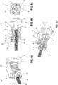
- FIG. 1 to 7 a first embodiment of a wall bracket 1 is shown.
- FIG. 8 to 11 a second embodiment of the wall bracket 1 is shown.
- the same parts are provided with the same reference numerals.
- the wall bracket 1 according to both embodiments comprises an anchor element 2, a threaded rod 6, a nut element 8 and a securing element 11.
- the anchor element 2 has a fastening section 3 for fastening the anchor element 2 to a building and a receiving section 4 extending from the fastening section 3 along a central axis M with a receiving opening 5 extending along the central axis M.
- the fastening section 3 is plate-like and has a lead-through opening 26 which is arranged offset to the side with respect to the central axis M and through which a fastening element, such as a screw, can be passed.
- the anchor element 2 can then be connected to a building via this screw.
- the receiving section 4 extends away from the fastening section 3 and serves to receive or support the threaded rod 6, the nut element 8 and the securing element 11.
- the threaded rod 6 is movably supported in the receiving opening 5.
- the threaded rod 6 has an external thread 7.
- the threaded rod 6 can be associated with a mounting frame or a sanitary article, for example. This can the mounting frame or the sanitary ware are firmly connected to the building.
- the nut element 8 is designed with an internal thread 9, which is interrupted on the circumferential side by a thread-free passage 10. On the outside, the nut element 8 has a drive structure 34 via which the nut element 8 can be actuated.
- the receiving section 4 has an external thread 12 on its front side opposite the fastening section 3.
- the nut element 8 with the internal thread 9 is pivotably mounted on this external thread 12. This means that the nut element 8 can be screwed onto the external thread 12 of the receiving section 4.
- the nut element 8 can be moved from a coarse adjustment position G via a fine adjustment position F into a clamping position K.
- the coarse adjustment position G the threaded rod 6 can be displaced relative to the receiving opening 5 along a longitudinal movement.
- the fine adjustment position F the external thread 7 of the threaded rod 6 is in engagement with the internal thread 9 of the nut element 8 and by turning the threaded rod 6 its position can be finely adjusted.
- the nut element 8 clamps the threaded rod 6 so that it cannot be moved any further.
- the nut element 9 is in the coarse adjustment position G.
- the coarse adjustment position G the nut element 9 is positioned such that the external thread 7 of the threaded rod 6 lies in the passage 10. This means that the external thread 7 of the threaded rod 6 is not in engagement with the internal thread 9 of the nut element 8.
- the threaded rod 6 can be freely displaced in the receiving opening 5 in the direction of the central axis M.
- the external thread 7 of the threaded rod 6 is therefore not in engagement with another thread and can therefore be freely displaced in the direction of the central axis M.
- This free shifting has the advantage that an installer can quickly position the threaded rod 6. It is therefore a matter of a rough setting of the required position of the threaded rod 6.
- the nut element 8 is pivoted about the central axis M so that it comes to rest in a fine adjustment position F.
- the fine adjustment position F is shown.
- the nut element 8 is positioned in such a way that the external thread 7 of the threaded rod 6 is in engagement with the internal thread 9 of the nut element 8. the Due to the engagement between the external thread 7 of the threaded rod 6 and the internal thread 9 of the nut element 8, the threaded rod 6 is no longer freely movable as in the coarse adjustment position G, but the threaded rod 6 must be rotated, which then results in a longitudinal movement due to the threaded engagement .
- the nut element 8 is pivoted from the coarse adjustment position G into the fine adjustment position F essentially by 180 °.
- the fitter can set the exact position of the threaded rod 6. It is a fine setting, especially accurate to the millimeter.
- the fine adjustment is of great advantage for the installer because the threaded rod can be aligned very precisely with respect to other elements, such as a mounting frame or a sanitary article.
- the nut element 8 is moved from the fine adjustment position F into the clamping position K by the securing element 11.
- the fuse element 11 is from a starting position A, as in Figures 3a to 3d and 10a to 10b, respectively, moved in the direction of the central axis M into a securing position S.
- the security layer S is in the Figures 4a to 4d and 11a to 11b shown in more detail.
- the securing element 11 moves the nut element 8 with the internal thread 8 radially to the threaded rod 6 into its clamping position. In the clamping position, the internal thread 9 of the nut element 8 is clamped radially to the external thread 7 of the threaded rod 6.
- the inside 24 of the receiving opening 5 also has an internally threaded section 18.
- the internally threaded section 18 extends only over a partial area from the inside 24 of the receiving opening 5, that is, the internally threaded section 18 does not extend through 360 ° around the central axis, but only over an angular range of approximately 90 °.
- the passage 10 is dimensioned such that when the nut element 8 is in the coarse adjustment position G, the external thread 7 of the threaded rod 6 is not in engagement with the internal thread section 18, but is spaced from it. This can be done in the Figures 2a and 9b can be recognized well.
- the threaded rod 6 is with the external thread 7 radially spaced from the Internal thread section 18, so that no engagement between the external thread 7 of the threaded rod 6 and the internal thread section 18 of the receiving opening 5 is provided. If the nut element 8 is now moved into the fine adjustment position F, the threaded rod 8 is moved radially to the central axis M into the internal thread section 18 and the external thread 7 of the threaded rod 6 engages both the internal thread 9 of the nut element 8 and the internal thread section 18 of the receiving opening 5 one. In the clamping position K, the external thread 7 of the threaded rod 6 is pressed radially into the internal thread section 18 by the nut element 8 and clamped there.
- the internally threaded section 18 has the advantage that the force transmission in the clamping position can be improved.
- the internal thread section 18 can be dispensed with, the external thread 7 of the threaded rod 6 engaging exclusively with the internal thread 9 of the nut element and resting against the inside 24 of the receiving opening 5.
- the external thread 12 of the receiving section 4 preferably extends at most at an angle of 300 ° around the central axis M, as shown in the figures.
- the internal thread 9 of the nut element 8 preferably extends around the central axis M at an angle of at most 300 °.
- the passage 10 extends around the central axis M around the remaining angle. The remaining angle is in a range of at least 60 °. The angles can vary depending on the dimensions.
- the passage is dimensioned in such a way that the threaded rod can be moved freely in the coarse adjustment position. This means that there is then no engagement between the internal thread of the nut element and the external thread of the threaded rod and the threaded rod can be displaced unhindered.
- the passage 10 extends, as shown in the figures, from the internal thread 9 of the nut element 8 radially into the nut element 8.
- the passage 10 penetrates the entire width of the nut element 8 as seen in the direction of the central axis M.
- the nut element 8 also has a recess 25.
- the recess 25 is in the Figures 2a to 2d as well as in the Figure 6b shown.
- the securing element 11 protrudes into this recess 25 when the nut element 8 is in the coarse adjustment position G.
- the nut element 8 is secured against rotation and there can be no displacement, which is particularly advantageous for delivery.
- the nut element 8 has to be moved out of the recess 25.
- the recess 25 is here part of a further recess 37 which extends around the central axis M by 180 °.
- the securing element 11 protrudes into the further recess 37 with the engagement section.
- the end regions 38 of the recess 37 provide a stop for the nut element 8.
- the recess 37 merges into the passage 10 and the end area 38 in the area of the passage 10 is provided by its side wall.
- the securing element 11 is mounted on the outside of the receiving section 4 in a longitudinal guide 13 so as to be longitudinally displaceable and non-rotatably mounted with respect to the central axis M.
- the longitudinal guide is a groove extending in the direction of the central axis M on the outside of the receiving section.
- the longitudinal guide is an elevation extending in the direction of the central axis M on the outside of the receiving section.
- the securing element 11 has an engagement structure 35 which is complementary to the groove or elevation. The engagement structure 35 can be provided by the securing element 11.
- the securing element is from a starting position A, as in the Figures 3a to 3d and 10a and 10b shown in a securing layer S, as in the Figures 4a to 4d and in the Figures 11a to 11b shown movable.
- the securing element 11 engages in the nut element 8 in such a way that it is pressed radially against the external thread 7 of the threaded rod 6 by the securing element 11 and is secured with respect to a rotary movement about the central axis M.
- the securing element 11 engages in the passage 10 one.
- the securing element 11 has an engagement section 14.
- the engagement section 14 can be pushed into the passage 10 accordingly.
- the engagement section 14 of the securing element 11 is formed by two spring legs 16.
- the spring legs 16 are brought together accordingly at the free end 15 of the engagement section 14. These spring legs 16 ensure that a corresponding force is exerted radially on the threaded rod 6.
- the engagement section is designed as a rigid element.
- the securing element 11 is secured in the securing position S with a latching connection 17 between the securing element 11 and the receiving section 4 to move out of the securing position S into the starting position A.
- the latching connection 17 has a latching lug 27 on the engagement section 14 and a latching opening 28 on the receiving section 4.
- the locking lug 27 engages, as in the Figure 4b shown, in the latching opening 28 accordingly.
- the latching connection 17 is provided by a latching lug 29, which is molded onto the securing element 11, and by a latching surface 30 which protrudes from the receiving section 4. It will be on the Figures 11a and 11b referenced.
- the securing element 11 also has a bearing section 19 with a bearing surface 20.
- the bearing surface 20 is designed as a circular cylinder.
- the bearing section 19 has the shape of a ring.
- the bearing surface 20 is in two-dimensional contact on an outside surface 21 lying on the receiving section 4.
- the surface 21 is essentially cylindrical.
- the bearing surface 20 is also cylindrical.
- the bearing surface does not extend completely around the central axis M, however.
- the receiving section 4 also has a surface 21 which is designed to be complementary to the bearing surface 20.
- both embodiments have stop elements 31, which the movement of the securing element 11 between the starting position and the security position or between the security position S and the starting position A accordingly.
- the stop elements 31 extend from the surface 21 and the bearing surface 20 and can provide a corresponding stop.
- the wall bracket 1 also has a support element 22.
- the support element 22 is arranged on the securing element 11 and comprises at least one support surface 23.
- the support element 22 and the securing element 11 are designed as two separate elements.
- the support element 22 has a receiving groove 32 in which the securing element 11 engages with an annular outer side 33. Via the connection between the receiving groove 32 and the annular receiving side 33, the support element 22 can be pivoted correspondingly to the securing element 11. As a result, the support surface 23 can be aligned according to the requirements of the assembly.
- the support element 22 is shown in a pivoted position.
- the support element 23 can further be supported with a support surface 36 on the receiving section 4.
- the securing element 11 and the support element 22 are formed in one piece. A corresponding alignment of the support surface 23 is not possible.
- the rotation of the nut element 8 is preferably limited in both embodiments by a stop.
- the stop is preferably provided by the securing element 11.
Landscapes
- Engineering & Computer Science (AREA)
- General Engineering & Computer Science (AREA)
- Mechanical Engineering (AREA)
- Clamps And Clips (AREA)
Priority Applications (2)
| Application Number | Priority Date | Filing Date | Title |
|---|---|---|---|
| PL20181074.4T PL3926185T3 (pl) | 2020-06-19 | 2020-06-19 | Uchwyt ścienny |
| EP20181074.4A EP3926185B1 (fr) | 2020-06-19 | 2020-06-19 | Support mural |
Applications Claiming Priority (1)
| Application Number | Priority Date | Filing Date | Title |
|---|---|---|---|
| EP20181074.4A EP3926185B1 (fr) | 2020-06-19 | 2020-06-19 | Support mural |
Publications (3)
| Publication Number | Publication Date |
|---|---|
| EP3926185A1 true EP3926185A1 (fr) | 2021-12-22 |
| EP3926185C0 EP3926185C0 (fr) | 2023-06-07 |
| EP3926185B1 EP3926185B1 (fr) | 2023-06-07 |
Family
ID=71111326
Family Applications (1)
| Application Number | Title | Priority Date | Filing Date |
|---|---|---|---|
| EP20181074.4A Active EP3926185B1 (fr) | 2020-06-19 | 2020-06-19 | Support mural |
Country Status (2)
| Country | Link |
|---|---|
| EP (1) | EP3926185B1 (fr) |
| PL (1) | PL3926185T3 (fr) |
Families Citing this family (1)
| Publication number | Priority date | Publication date | Assignee | Title |
|---|---|---|---|---|
| WO2026022003A1 (fr) * | 2024-07-23 | 2026-01-29 | Geberit International Ag | Agencement de palier pour une unité d'actionnement d'un réservoir dissimulé, et raccord à vis |
Citations (4)
| Publication number | Priority date | Publication date | Assignee | Title |
|---|---|---|---|---|
| US4125049A (en) * | 1976-05-10 | 1978-11-14 | Price Jr Ellie E | Laterally engageable and releasable nut assembly for threaded shafts |
| EP0786562A1 (fr) | 1996-01-25 | 1997-07-30 | Geberit Technik Ag | Support mural sur un cadre de montage |
| EP3404151A1 (fr) * | 2017-05-17 | 2018-11-21 | Viega Technology GmbH & Co. KG | Dispositif de fixation d'un objet sanitaire et utilisation d'un tel dispositif |
| EP3428353A1 (fr) | 2017-07-11 | 2019-01-16 | Geberit International AG | Élément de retenue mural pour un article sanitaire |
-
2020
- 2020-06-19 EP EP20181074.4A patent/EP3926185B1/fr active Active
- 2020-06-19 PL PL20181074.4T patent/PL3926185T3/pl unknown
Patent Citations (4)
| Publication number | Priority date | Publication date | Assignee | Title |
|---|---|---|---|---|
| US4125049A (en) * | 1976-05-10 | 1978-11-14 | Price Jr Ellie E | Laterally engageable and releasable nut assembly for threaded shafts |
| EP0786562A1 (fr) | 1996-01-25 | 1997-07-30 | Geberit Technik Ag | Support mural sur un cadre de montage |
| EP3404151A1 (fr) * | 2017-05-17 | 2018-11-21 | Viega Technology GmbH & Co. KG | Dispositif de fixation d'un objet sanitaire et utilisation d'un tel dispositif |
| EP3428353A1 (fr) | 2017-07-11 | 2019-01-16 | Geberit International AG | Élément de retenue mural pour un article sanitaire |
Also Published As
| Publication number | Publication date |
|---|---|
| EP3926185C0 (fr) | 2023-06-07 |
| EP3926185B1 (fr) | 2023-06-07 |
| PL3926185T3 (pl) | 2023-09-04 |
Similar Documents
| Publication | Publication Date | Title |
|---|---|---|
| EP2520877B1 (fr) | Dispositif de serrage pour module PV | |
| EP1694257A2 (fr) | Implant pour colonne vertebrale pouvant etre ajuste en longueur | |
| EP3714174B1 (fr) | Insert fileté en fil métallique | |
| EP4039897B1 (fr) | Support mural | |
| EP2226517A1 (fr) | Composant | |
| EP3721102B1 (fr) | Écrou en deux parties présentant une force de pression élevée | |
| EP3392419B1 (fr) | Système de fixation | |
| EP3926185A1 (fr) | Support mural | |
| DE2020782A1 (de) | Sicherungsmutter | |
| WO2008012074A1 (fr) | Écrou de blocage | |
| WO2017012611A1 (fr) | Système de fixation pour la fixation d'une structure de toit dans un secteur sur le toit d'une armoire électrique | |
| AT2954U1 (de) | Schnellmontagetopf für möbelscharniere | |
| EP0774590B1 (fr) | Dispositif de tension pour câble de commande | |
| DE3149217A1 (de) | "vierteldrehungsmutter" | |
| EP3462044A1 (fr) | Élément de fixation | |
| DE4316808C2 (de) | Spannstück für Rohrelemente | |
| EP3879130B1 (fr) | Dispositif de montage pour plaque de recouvrement | |
| DE102019218637A1 (de) | Spindelantrieb und Verfahren zur Montage eines Spindelantriebs | |
| EP4119737B1 (fr) | Dispositif de retenue en particulier pour l'évacuation des eaux des toitures plates | |
| EP4069986B1 (fr) | Douille à partie filetée dégagée permettant de recevoir un élément de fixation | |
| WO2018046140A1 (fr) | Système à ferrure et à profilé | |
| EP3421675B1 (fr) | Système de montage | |
| EP4306727A1 (fr) | Tringles de bouche d'incendie, bouche d'incendie, ainsi que procédé de réglage de la longueur des tringles de bouche d'incendie | |
| EP4675114A1 (fr) | Ensemble de fixation, structure de composant comprenant l'ensemble de fixation et procédé de fixation associé | |
| DE10052915A1 (de) | Mutter mit einer Klemmsicherung |
Legal Events
| Date | Code | Title | Description |
|---|---|---|---|
| PUAI | Public reference made under article 153(3) epc to a published international application that has entered the european phase |
Free format text: ORIGINAL CODE: 0009012 |
|
| STAA | Information on the status of an ep patent application or granted ep patent |
Free format text: STATUS: THE APPLICATION HAS BEEN PUBLISHED |
|
| AK | Designated contracting states |
Kind code of ref document: A1 Designated state(s): AL AT BE BG CH CY CZ DE DK EE ES FI FR GB GR HR HU IE IS IT LI LT LU LV MC MK MT NL NO PL PT RO RS SE SI SK SM TR |
|
| B565 | Issuance of search results under rule 164(2) epc |
Effective date: 20201119 |
|
| STAA | Information on the status of an ep patent application or granted ep patent |
Free format text: STATUS: REQUEST FOR EXAMINATION WAS MADE |
|
| 17P | Request for examination filed |
Effective date: 20220421 |
|
| RBV | Designated contracting states (corrected) |
Designated state(s): AL AT BE BG CH CY CZ DE DK EE ES FI FR GB GR HR HU IE IS IT LI LT LU LV MC MK MT NL NO PL PT RO RS SE SI SK SM TR |
|
| GRAP | Despatch of communication of intention to grant a patent |
Free format text: ORIGINAL CODE: EPIDOSNIGR1 |
|
| STAA | Information on the status of an ep patent application or granted ep patent |
Free format text: STATUS: GRANT OF PATENT IS INTENDED |
|
| INTG | Intention to grant announced |
Effective date: 20220921 |
|
| GRAS | Grant fee paid |
Free format text: ORIGINAL CODE: EPIDOSNIGR3 |
|
| GRAA | (expected) grant |
Free format text: ORIGINAL CODE: 0009210 |
|
| STAA | Information on the status of an ep patent application or granted ep patent |
Free format text: STATUS: THE PATENT HAS BEEN GRANTED |
|
| AK | Designated contracting states |
Kind code of ref document: B1 Designated state(s): AL AT BE BG CH CY CZ DE DK EE ES FI FR GB GR HR HU IE IS IT LI LT LU LV MC MK MT NL NO PL PT RO RS SE SI SK SM TR |
|
| REG | Reference to a national code |
Ref country code: GB Ref legal event code: FG4D Free format text: NOT ENGLISH |
|
| REG | Reference to a national code |
Ref country code: CH Ref legal event code: EP Ref country code: AT Ref legal event code: REF Ref document number: 1575902 Country of ref document: AT Kind code of ref document: T Effective date: 20230615 Ref country code: DE Ref legal event code: R096 Ref document number: 502020003503 Country of ref document: DE |
|
| U01 | Request for unitary effect filed |
Effective date: 20230608 |
|
| U07 | Unitary effect registered |
Designated state(s): AT BE BG DE DK EE FI FR IT LT LU LV MT NL PT SE SI Effective date: 20230619 |
|
| U20 | Renewal fee for the european patent with unitary effect paid |
Year of fee payment: 4 Effective date: 20230613 |
|
| REG | Reference to a national code |
Ref country code: LT Ref legal event code: MG9D |
|
| PG25 | Lapsed in a contracting state [announced via postgrant information from national office to epo] |
Ref country code: NO Free format text: LAPSE BECAUSE OF FAILURE TO SUBMIT A TRANSLATION OF THE DESCRIPTION OR TO PAY THE FEE WITHIN THE PRESCRIBED TIME-LIMIT Effective date: 20230907 Ref country code: ES Free format text: LAPSE BECAUSE OF FAILURE TO SUBMIT A TRANSLATION OF THE DESCRIPTION OR TO PAY THE FEE WITHIN THE PRESCRIBED TIME-LIMIT Effective date: 20230607 |
|
| PG25 | Lapsed in a contracting state [announced via postgrant information from national office to epo] |
Ref country code: RS Free format text: LAPSE BECAUSE OF FAILURE TO SUBMIT A TRANSLATION OF THE DESCRIPTION OR TO PAY THE FEE WITHIN THE PRESCRIBED TIME-LIMIT Effective date: 20230607 Ref country code: HR Free format text: LAPSE BECAUSE OF FAILURE TO SUBMIT A TRANSLATION OF THE DESCRIPTION OR TO PAY THE FEE WITHIN THE PRESCRIBED TIME-LIMIT Effective date: 20230607 Ref country code: GR Free format text: LAPSE BECAUSE OF FAILURE TO SUBMIT A TRANSLATION OF THE DESCRIPTION OR TO PAY THE FEE WITHIN THE PRESCRIBED TIME-LIMIT Effective date: 20230908 |
|
| PG25 | Lapsed in a contracting state [announced via postgrant information from national office to epo] |
Ref country code: SK Free format text: LAPSE BECAUSE OF FAILURE TO SUBMIT A TRANSLATION OF THE DESCRIPTION OR TO PAY THE FEE WITHIN THE PRESCRIBED TIME-LIMIT Effective date: 20230607 |
|
| PG25 | Lapsed in a contracting state [announced via postgrant information from national office to epo] |
Ref country code: IS Free format text: LAPSE BECAUSE OF FAILURE TO SUBMIT A TRANSLATION OF THE DESCRIPTION OR TO PAY THE FEE WITHIN THE PRESCRIBED TIME-LIMIT Effective date: 20231007 |
|
| PG25 | Lapsed in a contracting state [announced via postgrant information from national office to epo] |
Ref country code: SM Free format text: LAPSE BECAUSE OF FAILURE TO SUBMIT A TRANSLATION OF THE DESCRIPTION OR TO PAY THE FEE WITHIN THE PRESCRIBED TIME-LIMIT Effective date: 20230607 Ref country code: SK Free format text: LAPSE BECAUSE OF FAILURE TO SUBMIT A TRANSLATION OF THE DESCRIPTION OR TO PAY THE FEE WITHIN THE PRESCRIBED TIME-LIMIT Effective date: 20230607 Ref country code: RO Free format text: LAPSE BECAUSE OF FAILURE TO SUBMIT A TRANSLATION OF THE DESCRIPTION OR TO PAY THE FEE WITHIN THE PRESCRIBED TIME-LIMIT Effective date: 20230607 Ref country code: IS Free format text: LAPSE BECAUSE OF FAILURE TO SUBMIT A TRANSLATION OF THE DESCRIPTION OR TO PAY THE FEE WITHIN THE PRESCRIBED TIME-LIMIT Effective date: 20231007 |
|
| REG | Reference to a national code |
Ref country code: DE Ref legal event code: R097 Ref document number: 502020003503 Country of ref document: DE |
|
| PG25 | Lapsed in a contracting state [announced via postgrant information from national office to epo] |
Ref country code: MC Free format text: LAPSE BECAUSE OF FAILURE TO SUBMIT A TRANSLATION OF THE DESCRIPTION OR TO PAY THE FEE WITHIN THE PRESCRIBED TIME-LIMIT Effective date: 20230607 |
|
| REG | Reference to a national code |
Ref country code: IE Ref legal event code: MM4A |
|
| PG25 | Lapsed in a contracting state [announced via postgrant information from national office to epo] |
Ref country code: MC Free format text: LAPSE BECAUSE OF FAILURE TO SUBMIT A TRANSLATION OF THE DESCRIPTION OR TO PAY THE FEE WITHIN THE PRESCRIBED TIME-LIMIT Effective date: 20230607 |
|
| PLBE | No opposition filed within time limit |
Free format text: ORIGINAL CODE: 0009261 |
|
| STAA | Information on the status of an ep patent application or granted ep patent |
Free format text: STATUS: NO OPPOSITION FILED WITHIN TIME LIMIT |
|
| PG25 | Lapsed in a contracting state [announced via postgrant information from national office to epo] |
Ref country code: IE Free format text: LAPSE BECAUSE OF NON-PAYMENT OF DUE FEES Effective date: 20230619 |
|
| PG25 | Lapsed in a contracting state [announced via postgrant information from national office to epo] |
Ref country code: IE Free format text: LAPSE BECAUSE OF NON-PAYMENT OF DUE FEES Effective date: 20230619 |
|
| 26N | No opposition filed |
Effective date: 20240308 |
|
| U1K | Transfer of rights of the unitary patent after the registration of the unitary effect |
Owner name: GEBERIT INTERNATIONAL AG; CH |
|
| U20 | Renewal fee for the european patent with unitary effect paid |
Year of fee payment: 5 Effective date: 20240612 |
|
| PGFP | Annual fee paid to national office [announced via postgrant information from national office to epo] |
Ref country code: PL Payment date: 20250602 Year of fee payment: 6 |
|
| PGFP | Annual fee paid to national office [announced via postgrant information from national office to epo] |
Ref country code: GB Payment date: 20250618 Year of fee payment: 6 |
|
| U20 | Renewal fee for the european patent with unitary effect paid |
Year of fee payment: 6 Effective date: 20250611 |
|
| PG25 | Lapsed in a contracting state [announced via postgrant information from national office to epo] |
Ref country code: CY Free format text: LAPSE BECAUSE OF FAILURE TO SUBMIT A TRANSLATION OF THE DESCRIPTION OR TO PAY THE FEE WITHIN THE PRESCRIBED TIME-LIMIT; INVALID AB INITIO Effective date: 20200619 |
|
| PGFP | Annual fee paid to national office [announced via postgrant information from national office to epo] |
Ref country code: CZ Payment date: 20250610 Year of fee payment: 6 |
|
| PG25 | Lapsed in a contracting state [announced via postgrant information from national office to epo] |
Ref country code: HU Free format text: LAPSE BECAUSE OF FAILURE TO SUBMIT A TRANSLATION OF THE DESCRIPTION OR TO PAY THE FEE WITHIN THE PRESCRIBED TIME-LIMIT; INVALID AB INITIO Effective date: 20200619 |
|
| PGFP | Annual fee paid to national office [announced via postgrant information from national office to epo] |
Ref country code: CH Payment date: 20250701 Year of fee payment: 6 |
|
| PG25 | Lapsed in a contracting state [announced via postgrant information from national office to epo] |
Ref country code: TR Free format text: LAPSE BECAUSE OF FAILURE TO SUBMIT A TRANSLATION OF THE DESCRIPTION OR TO PAY THE FEE WITHIN THE PRESCRIBED TIME-LIMIT Effective date: 20230607 |