EP3926232B1 - Phare pour un véhicule - Google Patents
Phare pour un véhicule Download PDFInfo
- Publication number
- EP3926232B1 EP3926232B1 EP21180441.4A EP21180441A EP3926232B1 EP 3926232 B1 EP3926232 B1 EP 3926232B1 EP 21180441 A EP21180441 A EP 21180441A EP 3926232 B1 EP3926232 B1 EP 3926232B1
- Authority
- EP
- European Patent Office
- Prior art keywords
- light
- low
- focal point
- incident surface
- lens
- Prior art date
- Legal status (The legal status is an assumption and is not a legal conclusion. Google has not performed a legal analysis and makes no representation as to the accuracy of the status listed.)
- Active
Links
Images




Classifications
-
- F—MECHANICAL ENGINEERING; LIGHTING; HEATING; WEAPONS; BLASTING
- F21—LIGHTING
- F21S—NON-PORTABLE LIGHTING DEVICES; SYSTEMS THEREOF; VEHICLE LIGHTING DEVICES SPECIALLY ADAPTED FOR VEHICLE EXTERIORS
- F21S41/00—Illuminating devices specially adapted for vehicle exteriors, e.g. headlamps
- F21S41/10—Illuminating devices specially adapted for vehicle exteriors, e.g. headlamps characterised by the light source
- F21S41/14—Illuminating devices specially adapted for vehicle exteriors, e.g. headlamps characterised by the light source characterised by the type of light source
- F21S41/141—Light emitting diodes [LED]
- F21S41/147—Light emitting diodes [LED] the main emission direction of the LED being angled to the optical axis of the illuminating device
-
- F—MECHANICAL ENGINEERING; LIGHTING; HEATING; WEAPONS; BLASTING
- F21—LIGHTING
- F21S—NON-PORTABLE LIGHTING DEVICES; SYSTEMS THEREOF; VEHICLE LIGHTING DEVICES SPECIALLY ADAPTED FOR VEHICLE EXTERIORS
- F21S41/00—Illuminating devices specially adapted for vehicle exteriors, e.g. headlamps
- F21S41/10—Illuminating devices specially adapted for vehicle exteriors, e.g. headlamps characterised by the light source
- F21S41/14—Illuminating devices specially adapted for vehicle exteriors, e.g. headlamps characterised by the light source characterised by the type of light source
- F21S41/141—Light emitting diodes [LED]
- F21S41/147—Light emitting diodes [LED] the main emission direction of the LED being angled to the optical axis of the illuminating device
- F21S41/148—Light emitting diodes [LED] the main emission direction of the LED being angled to the optical axis of the illuminating device the main emission direction of the LED being perpendicular to the optical axis
-
- F—MECHANICAL ENGINEERING; LIGHTING; HEATING; WEAPONS; BLASTING
- F21—LIGHTING
- F21S—NON-PORTABLE LIGHTING DEVICES; SYSTEMS THEREOF; VEHICLE LIGHTING DEVICES SPECIALLY ADAPTED FOR VEHICLE EXTERIORS
- F21S41/00—Illuminating devices specially adapted for vehicle exteriors, e.g. headlamps
- F21S41/20—Illuminating devices specially adapted for vehicle exteriors, e.g. headlamps characterised by refractors, transparent cover plates, light guides or filters
- F21S41/25—Projection lenses
- F21S41/265—Composite lenses; Lenses with a patch-like shape
-
- F—MECHANICAL ENGINEERING; LIGHTING; HEATING; WEAPONS; BLASTING
- F21—LIGHTING
- F21S—NON-PORTABLE LIGHTING DEVICES; SYSTEMS THEREOF; VEHICLE LIGHTING DEVICES SPECIALLY ADAPTED FOR VEHICLE EXTERIORS
- F21S41/00—Illuminating devices specially adapted for vehicle exteriors, e.g. headlamps
- F21S41/30—Illuminating devices specially adapted for vehicle exteriors, e.g. headlamps characterised by reflectors
- F21S41/32—Optical layout thereof
- F21S41/321—Optical layout thereof the reflector being a surface of revolution or a planar surface, e.g. truncated
-
- F—MECHANICAL ENGINEERING; LIGHTING; HEATING; WEAPONS; BLASTING
- F21—LIGHTING
- F21S—NON-PORTABLE LIGHTING DEVICES; SYSTEMS THEREOF; VEHICLE LIGHTING DEVICES SPECIALLY ADAPTED FOR VEHICLE EXTERIORS
- F21S41/00—Illuminating devices specially adapted for vehicle exteriors, e.g. headlamps
- F21S41/40—Illuminating devices specially adapted for vehicle exteriors, e.g. headlamps characterised by screens, non-reflecting members, light-shielding members or fixed shades
- F21S41/43—Illuminating devices specially adapted for vehicle exteriors, e.g. headlamps characterised by screens, non-reflecting members, light-shielding members or fixed shades characterised by the shape thereof
-
- F—MECHANICAL ENGINEERING; LIGHTING; HEATING; WEAPONS; BLASTING
- F21—LIGHTING
- F21S—NON-PORTABLE LIGHTING DEVICES; SYSTEMS THEREOF; VEHICLE LIGHTING DEVICES SPECIALLY ADAPTED FOR VEHICLE EXTERIORS
- F21S41/00—Illuminating devices specially adapted for vehicle exteriors, e.g. headlamps
- F21S41/60—Illuminating devices specially adapted for vehicle exteriors, e.g. headlamps characterised by a variable light distribution
- F21S41/65—Illuminating devices specially adapted for vehicle exteriors, e.g. headlamps characterised by a variable light distribution by acting on light sources
- F21S41/663—Illuminating devices specially adapted for vehicle exteriors, e.g. headlamps characterised by a variable light distribution by acting on light sources by switching light sources
-
- F—MECHANICAL ENGINEERING; LIGHTING; HEATING; WEAPONS; BLASTING
- F21—LIGHTING
- F21S—NON-PORTABLE LIGHTING DEVICES; SYSTEMS THEREOF; VEHICLE LIGHTING DEVICES SPECIALLY ADAPTED FOR VEHICLE EXTERIORS
- F21S45/00—Arrangements within vehicle lighting devices specially adapted for vehicle exteriors, for purposes other than emission or distribution of light
- F21S45/40—Cooling of lighting devices
- F21S45/47—Passive cooling, e.g. using fins, thermal conductive elements or openings
Definitions
- the invention relates to a headlamp device for a vehicle capable of emitting low beam and high beam light rays.
- a conventional headlamp device disclosed in Taiwanese Utility Model Patent No. M248960 includes a headlamp 80 and a headlight function switching device 90.
- the headlamp 80 includes a light emitting member 81, a reflecting member 82 and a lens 83.
- the light emitting member 81 generates light beams.
- the reflecting member 82 and the lens 83 are respectively located at two opposite sides of the light emitting member 81.
- the headlight function switching device 90 is disposed between the light emitting member 81 and the lens 83, and includes a fixed plate 901, a solenoid valve 902 and a blocking board 903.
- the solenoid valve 902 is fixedly mounted to the fixed plate 901.
- the blocking board 903 is operable by the solenoid valve 902 to move relative to the light emitting member 81 in an up-down direction between an upper position and a lower position.
- the blocking board 903 When the blocking board 903 is at the upper position, the light beams generated by the light emitting member 81 are reflected by the reflecting member 82 and propagate in such a manner that some of the light beams are blocked by the blocking board 903 while the remaining light beams pass through the lens 83 to serve as low beam light rays (see Figure 8 ) which form a light distribution pattern that has a clear cut-off line.
- the blocking board 903 When the blocking board 903 is at the lower position, the light beams generated by the light emitting member 81 are reflected by the reflecting member 82 and pass through the lens 83 without being blocked by the blocking board 903, so as to serve as high beam light rays (see Figure 7 ).
- the conventional headlamp device is switchable between a low beam mode where the low beam light rays are generated and a high beam mode where the high beam light rays are generated.
- the solenoid valve 902 may be slow to react to user input and is prone to malfunction. Once the solenoid valve 902 has malfunctioned, the conventional headlamp device can no longer switch between the low beam mode and the high beam mode.
- an object of the invention is to provide a headlamp device that can alleviate at least one of the drawbacks of the prior art.
- the headlamp device includes a compound lens unit, a low-beam reflector, a high-beam reflector, a blocking board and a light emitting unit.
- the compound lens unit includes an upper lens and a lower lens assembly.
- the upper lens has a low-beam optical axis, an upper light-incident surface, an upper light-emergent surface and an upper focal point.
- the upper light-incident surface and the upper light-emergent surface are respectively located at two opposite sides of the upper lens in a direction of the low-beam optical axis.
- the upper focal point is located at one side of the upper light-incident surface opposite to the upper light-emergent surface.
- the lower lens assembly is located below the upper lens, includes a plurality of lower lenses, and has a lower light-incident surface, a lower light-emergent surface and a lower focal point.
- the lower light-incident surface is cooperatively formed by the lower lenses, faces in a direction that is the same as that of the upper light-incident surface, and is offset from the upper light-incident surface.
- the lower light-emergent surface is cooperatively formed by the lower lenses, and is opposite to the lower light-incident surface in the direction of the low-beam optical axis.
- the lower focal point is located at one side of the lower light-incident surface opposite to the lower light-emergent surface.
- the low-beam reflector is located at one side of the upper focal point opposite to the upper light-incident surface, and has a low-beam reflecting surface that is arc-shaped and that has a first low-beam reflecting focal point and a second low-beam reflecting focal point.
- the first low-beam reflecting focal point and the second low-beam reflecting focal point are respectively distal from and proximate to the upper light-incident surface of the upper lens.
- the second low-beam reflecting focal point coincides with the upper focal point of the upper lens.
- the high-beam reflector is located at one side of the lower focal point opposite to the lower light-incident surface, and has a reflector axis and a high-beam reflecting surface.
- the high-beam reflecting surface is arc-shaped, and has a first high-beam reflecting focal point and a second high-beam reflecting focal point.
- the first high-beam reflecting focal point and the second high-beam reflecting focal point are respectively distal from and proximate to the lower light-incident surface of the lower lens assembly.
- the second high-beam reflecting focal point coincides with the lower focal point of the lower lens assembly.
- the first high-beam reflecting focal point and the second high-beam reflecting focal point are located on and cooperatively define the reflector axis.
- the blocking board has a top end at which the second low-beam focal point is located.
- the light emitting unit includes a first light source and a second light source.
- the first light source substantially coincides with the first low-beam reflecting focal point of the low-beam reflector.
- the second light source substantially coincides with the first high-beam reflecting focal point of the high-beam reflector.
- Each of the first light source and the second light source is operable to switch between an on-state in which light beams are generated, and an off-state in which light beams cease to be generated.
- the light beams generated by the first light source are reflected by the low-beam reflecting surface of the low-beam reflector such that some of the light beams are blocked by the blocking board while the remaining light beams travel into the upper lens through the upper light-incident surface and exit the upper lens through the upper light-emergent surface to serve as low beam light rays.
- the light beams generated by the second light source are reflected by the high-beam reflecting surface of the high-beam reflector such that the light beams travel into the lower lens assembly through the lower light-incident surface and exit the lower lens assembly through the lower light-emergent surface to serve as high beam light rays.
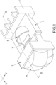
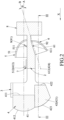
- an embodiment of a headlamp device is adapted for a vehicle, and includes a compound lens unit 4, a base 2, a low-beam reflector 5, a high-beam reflector 6, a blocking board 7 and a light emitting unit 9.
- the compound lens unit 4 includes an upper lens 41 and a lower lens assembly 42.
- the upper lens 41 has a low-beam optical axis (A), an upper light-incident surface 411, an upper light-emergent surface 412 and an upper focal point 413.
- the upper light-incident surface 411 and the upper light-emergent surface 412 are respectively located at two opposite sides of the upper lens 41 in a direction (X) of the low-beam optical axis (A).
- the upper light-emergent surface 412 is in front of the upper light-incident surface 411 with "front" being the forward-facing side of the headlamp device.
- the upper focal point 413 is located at one side of the upper light-incident surface 411 opposite to the upper light-emergent surface 412.
- the lower lens assembly 42 is located below the upper lens 41, includes a plurality of lower lenses 421, and has a lower light-incident surface 422, a lower light-emergent surface 423 and a lower focal point 424.
- the lower lenses 421 and the upper lens 41 are formed as one-piece.
- the lower light-incident surface 422 is cooperatively formed by the lower lenses 421, faces in a direction that is the same as that of the upper light-incident surface 411 of the upper lens 41, and is offset from the upper light-incident surface 411 in the direction (X) of the low-beam optical axis (A) (i.e., the lower light-incident surface 422 is not flush with the upper light-incident surface 411).
- the upper light-incident surface 411 is forwardly offset from the lower light-incident surface 422.
- the lower light-emergent surface 423 is cooperatively formed by the lower lenses 421, is opposite to the lower light-incident surface 422 in the direction (X) of the low-beam optical axis (A) of the upper lens 41, and has a first section 425 and two second sections 426 located below the low-beam optical axis (A).
- the second sections 426 are respectively located at two opposite sides of the first section 425 in a transverse direction (Y) transverse to the direction (X) of the low-beam optical axis (A) and are offset from the first section 425 in the direction (X) of the low-beam optical axis (A) (i.e., the lower light-emergent surface 423 is configured to not be a smooth surface).
- the lower focal point 424 is located at one side of the lower light-incident surface 422 opposite to the lower light-emergent surface 423.
- the lower lens assembly 42 of the compound lens unit 4 includes four lower lenses 421.
- the first section 425 of the lower light-emergent surface 423 is formed by two of the lower lenses 421, and the second sections 426 of the lower light-emergent surface 423 are respectively formed by the other two of the lower lenses 421.
- each of the upper lens 41 and the lower lenses 421 of the lower lens assembly 42 of the compound lens unit 4 is a plano-convex lens.
- the base 2 is located rearwardly of the upper lens 41 and the lower lens assembly 42, and is where the low-beam reflector 5, the high-beam reflector 6, the blocking board 7 and the light-emitting unit 9 are disposed on.
- the low-beam reflector 5 and the high-beam reflector 6 are respectively disposed at two opposite sides of the base 2.
- the low-beam reflector 5 is located at one side of the upper focal point 413 of the upper lens 41 opposite to the upper light-incident surface 411 of the upper lens 41, and has a low-beam reflecting surface 51 that is arc-shaped and that faces the upper light-incident surface 411.
- the low-beam reflecting surface 51 has a first low-beam reflecting focal point 511 and a second low-beam reflecting focal point 512.
- the first low-beam reflecting focal point 511 and the second low-beam reflecting focal point 512 are respectively distal from and proximate to the upper light-incident surface 411 of the upper lens 41.
- the second low-beam reflecting focal point 512 coincides with the upper focal point 413 of the upper lens 41.
- the high-beam reflector 6 is located at one side of the lower focal point 424 of the lower lens assembly 42 opposite to the lower light-incident surface 422 of the lower lens assembly 42, and has a reflector axis (B) and a high-beam reflecting surface 61.
- the high-beam reflecting surface 61 is arc-shaped, faces the lower light-incident surface 422, and has a first high-beam reflecting focal point 611 and a second high-beam reflecting focal point 612.
- the first high-beam reflecting focal point 611 and the second high-beam reflecting focal point 612 are respectively distal from and proximate to the lower light-incident surface 422 of the lower lens assembly 42.
- the second high-beam reflecting focal point 612 coincides with the lower focal point 424 of the lower lens assembly 42.
- the first high-beam reflecting focal point 611 and the second high-beam reflecting focal point 612 are located on and cooperatively define the reflector axis (B).
- the low-beam optical axis (A) of the upper lens 41 and the reflector axis (B) of the high-beam reflector 6 intersect, and cooperatively form an angle ( ⁇ ) of intersection.
- the angle ( ⁇ ) of intersection of the low-beam optical axis (A) and the reflector axis (B) is greater than 0 degree, but is not greater than 60 degrees.
- the blocking board 7 has a top end at which the second low-beam focal point 512 is located.
- the light emitting unit 9 includes a first light source 91 and a second light source 92.
- the first light source 91 substantially coincides with the first low-beam reflecting focal point 511 of the low-beam reflector 5.
- the second light source 92 substantially coincides with the first high-beam reflecting focal point 611 of the high-beam reflector 6.
- Each of the first light source 91 and the second light source 92 is operable to switch between an on-state in which light beams are generated, and an off-state in which light beams cease to be generated.
- Each of the first light source 91 and the second light source 92 is a light-emitting diode made of at least one semiconductor die.
- the light beams generated by the first light source 91 are reflected by the low-beam reflecting surface 51 of the low-beam reflector 5 such that some of the light beams are blocked by the blocking board 7 (i.e., some of the reflected light beams that do not perfectly pass through the second low-beam reflecting focal point 512 of the low-beam reflecting surface 51 are blocked by the blocking board 7) while the remaining light beams travel into the upper lens 41 through the upper light-incident surface 411 and exit the upper lens 41 through the upper light-emergent surface 412 to serve as low beam light rays.
- the blocking board 7 blocking some of the light beams, light distribution pattern formed by the low beam light rays has a clear cut-off line as shown in Figure 5 .
- the light beams generated by the second light source 92 are reflected by the high-beam reflecting surface 61 of the high-beam reflector 6 such that the light beams travel into the lower lens assembly 42 through the lower light-incident surface 422 and exit the lower lens assembly 42 through the lower light-emergent surface 423 to serve as high beam light rays.
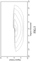
- Light distribution pattern formed by the high beam light rays is shown in Figure 6 .
- the compound lens unit 4 may provide relatively good stray-light rejection when the low beam light rays are generated. That is to say, when the first light source 91 is in the on-state and when the second light source 92 is in the off-state, the light beams generated by the first light source 91 but traveling in undesirable paths (namely, stray light) may be prevented from exiting the lower lens assembly 42 through the lower light-emergent surface 423. Therefore, stray light will not substantially affect the light distribution pattern formed by the low beam light rays.
- a distance between the upper light-incident surface 411 of the upper lens 41 and the lower light-incident surface 422 of the lower lens assembly 42 in the direction (X) of the low-beam optical axis (A) ranges from 1 to 30 millimeters.
- each individual one of the lower lenses 421 of the lower lens assembly 42 constitutes only one of the first section 425 and the second sections 426
- curvature of each of the first section 425 and the second sections 426 is individually adjustable by adjusting the curvature of the corresponding lower lens(es) 421.
- the high-beam reflector 6 may prevent the light beams generated by the second light source 92 from dispersing.
- the lower lens assembly 42 may achieve a better effect of focusing light so that the light beams exiting the lower lens assembly 42 through the lower light-emergent surface 423 may be adjusted to serve as the high beam light rays even when only the second light source 92 is in the on-state (i.e., for the high beam light rays to be generated, it is not necessary for the first light source 91 and the second light source 92 to simultaneously be in the on-state to create overlapping light beams or patterns). Consequently, the embodiment may be relatively energy-saving.
- the embodiment further includes a heat dissipating member 8 and a fixing frame 3.
- the heat dissipating member 8 is disposed on the base 2 and serves the purpose of heat dissipation.
- the fixing frame 3 is disposed in front of the base 2, connects the base 2 to the compound lens unit 4, and has the compound lens unit 4 disposed thereon.
- the upper lens 41 and the lower lens assembly 42 of the compound lens unit 4 are held fixedly by the fixing frame 3.
- the embodiment of the headlamp device is capable of emitting low beam light rays and high beam light rays and is switchable between the low-beam mode and the high-beam mode without a solenoid valve. Therefore, the headlamp device according to the disclosure may react relatively quickly when operated and may have a relatively long service life so reliability of the headlamp device is improved. Consequently, the drawbacks of the prior art have been alleviated and the purpose of the invention can certainly be fulfilled.
Landscapes
- Engineering & Computer Science (AREA)
- General Engineering & Computer Science (AREA)
- Physics & Mathematics (AREA)
- Microelectronics & Electronic Packaging (AREA)
- Optics & Photonics (AREA)
- Non-Portable Lighting Devices Or Systems Thereof (AREA)
Claims (10)
- Dispositif de phare prévu pour un véhicule, ledit dispositif de phare comprenant :une unité de lentille composée (4) comprenantune lentille supérieure (41) qui aun axe optique de feu de croisement (A),une surface supérieure de lumière incidente (411),une surface supérieure de lumière émergente (412), etun point focal supérieur (413), ladite surface supérieure de lumière incidente (411) et ladite surface supérieure de lumière émergente (412) étant situées de manière respective aux deux côtés opposés de ladite lentille supérieure (41) dans une direction (X) de l'axe optique de feu de croisement (A), ledit point focal supérieur (413) étant situé sur un côté de ladite surface supérieure de lumière incidente (411) à l'opposé de ladite surface supérieure de lumière émergente (412), etun ensemble de lentille inférieur (42) qui se trouve au-dessous de ladite lentille supérieure (41), qui comprend une pluralité de lentilles inférieures (421), et qui aune surface inférieure de lumière incidente (422) formée de manière coopérative par lesdites lentilles inférieures (421), faisant face dans une direction qui est la même que celle de ladite surface supérieure de lumière incidente (411), et décalée par rapport à ladite surface supérieure de lumière incidente (411),une surface inférieure de lumière émergente (423) formée de manière coopérative par lesdites lentilles inférieures (421), et à l'opposé de ladite surface inférieure de lumière incidente (422) dans la direction (X) de l'axe optique de feu de croisement (A), etun point focal inférieur (424) situé sur un côté de ladite surface inférieure de lumière incidente (422) à l'opposé de ladite surface inférieure de lumière émergente (423) ;un réflecteur de feu de croisement (5) situé sur un côté dudit point focal supérieur (413) à l'opposé de ladite surface supérieure de lumière incidente (411), et ayant une surface réfléchissante de feu de croisement (51) qui est en forme d'arc et qui aun premier point focal de réflexion de feu de croisement (511) et un deuxième point focal de réflexion de feu de croisement (512) respectivement à distance et à proximité de ladite surface supérieure de lumière incidente (411) de ladite lentille supérieure (41), ledit deuxième point focal de réflexion de feu de croisement (512) coïncidant avec ledit point focal supérieur (413) de ladite lentille supérieure (41) ;un réflecteur de feu de route (6) situé sur un côté dudit point focal inférieur (424) à l'opposé de ladite surface inférieure de lumière incidente (422), et ayantun axe de réflecteur (B), etune surface réfléchissante de feu de route (61) qui est en forme d'arc et qui aun premier point focal de réflexion de feu de route (611) et un deuxième point focal de réflexion de feu de route (612) respectivement à distance et à proximité de ladite surface inférieure de lumière incidente (422) dudit ensemble de lentille inférieur (42), ledit deuxième point focal de réflexion de feu de route (612) coïncidant avec ledit point focal inférieur (424) dudit ensemble de lentille inférieur (42), ledit premier point focal de réflexion de feu de route (611) et ledit deuxième point focal de réflexion de feu de route (612) se trouvant sur et définissant de manière coopérative ledit axe de réflecteur (B) ;une plaque de blocage (7) ayant une extrémité supérieure au niveau de laquelle se trouve ledit deuxième point focal de feu de croisement (512) ; etune unité d'émission de lumière (9) ;ledit dispositif de phare étant caractérisé en ce que :ladite unité d'émission de lumière (9) comprendune première source de lumière (91) qui coïncide sensiblement avec ledit premier point focal de réflexion de feu de croisement (511) dudit réflecteur de feu de croisement (5), etune deuxième source de lumière (92) qui coïncide sensiblement avec ledit premier point focal de réflexion de feu de route (611) dudit réflecteur de feu de route (6), chacune de ladite première source de lumière (91) et de ladite deuxième source de lumière (92) pouvant fonctionner pour commuter entre un état allumé dans lequel des faisceaux de lumière sont générés, et un état éteint dans lequel des faisceaux de lumière cessent d'être générés ;les faisceaux de lumière générés par ladite première source de lumière (91) étant réfléchis par ladite surface réfléchissante de feu de croisement (51) dudit réflecteur de feu de croisement (5) de telle sorte que certains des faisceaux de lumière sont bloqués par ladite plaque de blocage (7) tandis que les faisceaux de lumière restants se déplacent dans ladite lentille supérieure (41) à travers ladite surface supérieure de lumière incidente (411) et sortent de ladite lentille supérieure (41) à travers ladite surface supérieure de lumière émergente (412) pour servir de rayons de lumière de feu de croisement, quand ladite première source de lumière (91) est dans l'état allumé et quand ladite deuxième source de lumière (92) est dans l'état éteint ; etles faisceaux de lumière générés par ladite deuxième source de lumière (92) étant réfléchis par ladite surface réfléchissante de feu de route (61) dudit réflecteur de feu de route (6) de telle sorte que les faisceaux de lumière se déplacent dans ledit ensemble de lentille inférieur (42) à travers ladite surface inférieure de lumière incidente (422) et sortent dudit ensemble de lentille inférieur (42) à travers ladite surface inférieure de lumière émergente (423) pour servir de rayons de lumière de feu de route, quand ladite deuxième source de lumière (92) est dans l'état allumé.
- Dispositif de phare selon la revendication 1, caractérisé en ce que l'axe optique de feu de croisement (A) de ladite lentille supérieure (41) et l'axe de réflecteur (B) dudit réflecteur de feu de route (6) se coupent, et forment de manière coopérative un angle (Θ) d'intersection.
- Dispositif de phare selon la revendication 2, caractérisé en ce que ledit angle (θ) d'intersection de l'axe optique de feu de croisement (A) et de l'axe de réflecteur (B) est supérieur à 0 degré, et est inférieur ou égal à 60 degrés.
- Dispositif de phare selon la revendication 1, caractérisé en ce que :ladite surface supérieure de lumière émergente (412) est devant ladite surface supérieure de lumière incidente (411) de ladite lentille supérieure (41) de ladite unité de lentille composée (4) ; etladite surface supérieure de lumière incidente (411) de ladite lentille supérieure (41) de ladite unité de lentille composée (4) est décalée vers l'avant par rapport à ladite surface inférieure de lumière incidente (422).
- Dispositif de phare selon la revendication 4, caractérisé en ce qu'une distance entre ladite surface supérieure de lumière incidente (411) de ladite lentille supérieure (41) et ladite surface inférieure de lumière incidente (422) dudit ensemble de lentille inférieur (42) dans la direction (X) de l'axe optique de feu de croisement (A) s'étend de 1 à 30 millimètres.
- Dispositif de phare selon la revendication 1, caractérisé en ce que ladite surface inférieure de lumière émergente (423) aune première section (425), etdeux deuxièmes sections (426) respectivement situées aux deux côtés opposés de ladite première section (425) dans une direction transversale (Y) transversale à la direction (X) de l'axe optique de feu de croisement (A), lesdites deuxièmes sections (426) étant décalées par rapport à ladite première section (425).
- Dispositif de phare selon la revendication 6, caractérisé en ce que :ledit ensemble de lentille inférieur (42) de ladite unité de lentille composée (4) comprend quatre desdites lentilles inférieures (421) ; etladite première section (425) de ladite surface inférieure de lumière émergente (423) dudit ensemble de lentille inférieur (42) est formée par deux desdites lentilles inférieures (421), et lesdites deuxièmes sections (426) de ladite surface inférieure de lumière émergente (423) sont formées de manière respective par les deux autres lentilles desdites lentilles inférieures (421).
- Dispositif de phare selon la revendication 1, caractérisé en ce que ladite lentille supérieure (41) et lesdites lentilles inférieures (421) sont formées comme une seule pièce.
- Dispositif de phare selon la revendication 1, caractérisé en ce que chacune de ladite première source de lumière (91) et de ladite deuxième source de lumière (92) de ladite unité d'émission de lumière (9) est une diode électroluminescente composée d'au moins une plaquette de semi-conducteur.
- Dispositif de phare selon la revendication 1, caractérisé en outre par une base (2) sur laquelle ledit réflecteur de feu de croisement (5), ledit réflecteur de feu de route (6), ladite plaque de blocage (7) et ladite unité d'émission de lumière (9) sont disposés.
Applications Claiming Priority (1)
| Application Number | Priority Date | Filing Date | Title |
|---|---|---|---|
| TW109120993A TWI721914B (zh) | 2020-06-20 | 2020-06-20 | 車用照明裝置 |
Publications (3)
| Publication Number | Publication Date |
|---|---|
| EP3926232A1 EP3926232A1 (fr) | 2021-12-22 |
| EP3926232C0 EP3926232C0 (fr) | 2023-08-23 |
| EP3926232B1 true EP3926232B1 (fr) | 2023-08-23 |
Family
ID=76036057
Family Applications (1)
| Application Number | Title | Priority Date | Filing Date |
|---|---|---|---|
| EP21180441.4A Active EP3926232B1 (fr) | 2020-06-20 | 2021-06-18 | Phare pour un véhicule |
Country Status (2)
| Country | Link |
|---|---|
| EP (1) | EP3926232B1 (fr) |
| TW (1) | TWI721914B (fr) |
Families Citing this family (2)
| Publication number | Priority date | Publication date | Assignee | Title |
|---|---|---|---|---|
| CN117091098A (zh) * | 2022-05-11 | 2023-11-21 | 嘉兴海拉灯具有限公司 | 车用远近一体灯 |
| TW202500417A (zh) * | 2023-06-15 | 2025-01-01 | 巨鎧精密工業股份有限公司 | 車燈裝置 |
Family Cites Families (9)
| Publication number | Priority date | Publication date | Assignee | Title |
|---|---|---|---|---|
| JP4615417B2 (ja) * | 2005-10-13 | 2011-01-19 | 株式会社小糸製作所 | 車両用前照灯の灯具ユニット |
| JP2011100583A (ja) * | 2009-11-04 | 2011-05-19 | Koito Mfg Co Ltd | 光学ユニット |
| JP2014082164A (ja) * | 2012-10-18 | 2014-05-08 | Ichikoh Ind Ltd | 車両用灯具 |
| JP6205713B2 (ja) * | 2012-11-13 | 2017-10-04 | 市光工業株式会社 | 車両用灯具 |
| FR3026466B1 (fr) * | 2014-09-30 | 2020-03-20 | Valeo Vision Belgique | Dispositif lumineux de vehicule avec des moyens de positionnement d'une carte electronique |
| JP6627282B2 (ja) * | 2015-06-30 | 2020-01-08 | 市光工業株式会社 | 車両用前照灯 |
| CN106813176A (zh) * | 2015-11-27 | 2017-06-09 | 欧司朗有限公司 | 一种车前灯 |
| TWM539600U (zh) * | 2016-04-01 | 2017-04-11 | Adi Optics Co Ltd | 車燈裝置及其光源模組 |
| TWI650257B (zh) * | 2018-02-13 | 2019-02-11 | 誠益光電科技股份有限公司 | 光線投射裝置 |
-
2020
- 2020-06-20 TW TW109120993A patent/TWI721914B/zh active
-
2021
- 2021-06-18 EP EP21180441.4A patent/EP3926232B1/fr active Active
Also Published As
| Publication number | Publication date |
|---|---|
| TW202200930A (zh) | 2022-01-01 |
| EP3926232C0 (fr) | 2023-08-23 |
| TWI721914B (zh) | 2021-03-11 |
| EP3926232A1 (fr) | 2021-12-22 |
Similar Documents
| Publication | Publication Date | Title |
|---|---|---|
| US11879608B2 (en) | Automotive lamp optical element, automotive lamp module, and vehicle | |
| EP2119958B1 (fr) | Lampe pour véhicule | |
| EP3647653B1 (fr) | Phare de véhicule | |
| JP5077543B2 (ja) | 車両用灯具ユニット | |
| EP3480515B1 (fr) | Lampe de véhicule | |
| EP2767750B1 (fr) | Phare de véhicule | |
| JP2022189607A (ja) | 車両用灯具 | |
| CN112469941A (zh) | 前灯装置 | |
| CN103906970A (zh) | 车辆头灯 | |
| JP2018078099A (ja) | ライトガイドを備えた自動車両用の照明装置 | |
| WO2020075536A1 (fr) | Guide de lumière pour véhicules, et lampe pour véhicules | |
| EP3926232A1 (fr) | Phare pour un véhicule | |
| EP3916291B1 (fr) | Dispositif de phare pour véhicule | |
| CN113847577B (zh) | 车用照明装置 | |
| JP2021111446A (ja) | 車両用灯具 | |
| TWM601310U (zh) | 車用照明裝置 | |
| JP7577673B2 (ja) | 車両用灯具 | |
| JP7268339B2 (ja) | 車両用導光体、光源ユニット及び車両用前照灯 | |
| JP7665783B2 (ja) | 自動車両の発光システムの光学モジュール | |
| JPWO2019124188A1 (ja) | 車両用前照灯 | |
| KR20220111063A (ko) | 차량용 램프 모듈 및 그 램프 모듈을 포함하는 차량용 램프 | |
| WO2024071263A1 (fr) | Phare de véhicule | |
| EP4050251B1 (fr) | Dispositif de phare pour véhicule | |
| EP4624800A1 (fr) | Phare de véhicule | |
| CN220540932U (zh) | 车辆用灯具 |
Legal Events
| Date | Code | Title | Description |
|---|---|---|---|
| PUAI | Public reference made under article 153(3) epc to a published international application that has entered the european phase |
Free format text: ORIGINAL CODE: 0009012 |
|
| STAA | Information on the status of an ep patent application or granted ep patent |
Free format text: STATUS: THE APPLICATION HAS BEEN PUBLISHED |
|
| AK | Designated contracting states |
Kind code of ref document: A1 Designated state(s): AL AT BE BG CH CY CZ DE DK EE ES FI FR GB GR HR HU IE IS IT LI LT LU LV MC MK MT NL NO PL PT RO RS SE SI SK SM TR |
|
| B565 | Issuance of search results under rule 164(2) epc |
Effective date: 20211022 |
|
| STAA | Information on the status of an ep patent application or granted ep patent |
Free format text: STATUS: REQUEST FOR EXAMINATION WAS MADE |
|
| 17P | Request for examination filed |
Effective date: 20220616 |
|
| RBV | Designated contracting states (corrected) |
Designated state(s): AL AT BE BG CH CY CZ DE DK EE ES FI FR GB GR HR HU IE IS IT LI LT LU LV MC MK MT NL NO PL PT RO RS SE SI SK SM TR |
|
| GRAP | Despatch of communication of intention to grant a patent |
Free format text: ORIGINAL CODE: EPIDOSNIGR1 |
|
| STAA | Information on the status of an ep patent application or granted ep patent |
Free format text: STATUS: GRANT OF PATENT IS INTENDED |
|
| INTG | Intention to grant announced |
Effective date: 20230309 |
|
| GRAS | Grant fee paid |
Free format text: ORIGINAL CODE: EPIDOSNIGR3 |
|
| GRAA | (expected) grant |
Free format text: ORIGINAL CODE: 0009210 |
|
| STAA | Information on the status of an ep patent application or granted ep patent |
Free format text: STATUS: THE PATENT HAS BEEN GRANTED |
|
| AK | Designated contracting states |
Kind code of ref document: B1 Designated state(s): AL AT BE BG CH CY CZ DE DK EE ES FI FR GB GR HR HU IE IS IT LI LT LU LV MC MK MT NL NO PL PT RO RS SE SI SK SM TR |
|
| REG | Reference to a national code |
Ref country code: GB Ref legal event code: FG4D |
|
| REG | Reference to a national code |
Ref country code: CH Ref legal event code: EP |
|
| REG | Reference to a national code |
Ref country code: IE Ref legal event code: FG4D |
|
| REG | Reference to a national code |
Ref country code: DE Ref legal event code: R096 Ref document number: 602021004453 Country of ref document: DE |
|
| U01 | Request for unitary effect filed |
Effective date: 20230901 |
|
| U07 | Unitary effect registered |
Designated state(s): AT BE BG DE DK EE FI FR IT LT LU LV MT NL PT SE SI Effective date: 20230908 |
|
| PG25 | Lapsed in a contracting state [announced via postgrant information from national office to epo] |
Ref country code: GR Free format text: LAPSE BECAUSE OF FAILURE TO SUBMIT A TRANSLATION OF THE DESCRIPTION OR TO PAY THE FEE WITHIN THE PRESCRIBED TIME-LIMIT Effective date: 20231124 |
|
| PG25 | Lapsed in a contracting state [announced via postgrant information from national office to epo] |
Ref country code: IS Free format text: LAPSE BECAUSE OF FAILURE TO SUBMIT A TRANSLATION OF THE DESCRIPTION OR TO PAY THE FEE WITHIN THE PRESCRIBED TIME-LIMIT Effective date: 20231223 |
|
| PG25 | Lapsed in a contracting state [announced via postgrant information from national office to epo] |
Ref country code: RS Free format text: LAPSE BECAUSE OF FAILURE TO SUBMIT A TRANSLATION OF THE DESCRIPTION OR TO PAY THE FEE WITHIN THE PRESCRIBED TIME-LIMIT Effective date: 20230823 Ref country code: NO Free format text: LAPSE BECAUSE OF FAILURE TO SUBMIT A TRANSLATION OF THE DESCRIPTION OR TO PAY THE FEE WITHIN THE PRESCRIBED TIME-LIMIT Effective date: 20231123 Ref country code: IS Free format text: LAPSE BECAUSE OF FAILURE TO SUBMIT A TRANSLATION OF THE DESCRIPTION OR TO PAY THE FEE WITHIN THE PRESCRIBED TIME-LIMIT Effective date: 20231223 Ref country code: HR Free format text: LAPSE BECAUSE OF FAILURE TO SUBMIT A TRANSLATION OF THE DESCRIPTION OR TO PAY THE FEE WITHIN THE PRESCRIBED TIME-LIMIT Effective date: 20230823 Ref country code: GR Free format text: LAPSE BECAUSE OF FAILURE TO SUBMIT A TRANSLATION OF THE DESCRIPTION OR TO PAY THE FEE WITHIN THE PRESCRIBED TIME-LIMIT Effective date: 20231124 |
|
| PG25 | Lapsed in a contracting state [announced via postgrant information from national office to epo] |
Ref country code: PL Free format text: LAPSE BECAUSE OF FAILURE TO SUBMIT A TRANSLATION OF THE DESCRIPTION OR TO PAY THE FEE WITHIN THE PRESCRIBED TIME-LIMIT Effective date: 20230823 |
|
| PG25 | Lapsed in a contracting state [announced via postgrant information from national office to epo] |
Ref country code: ES Free format text: LAPSE BECAUSE OF FAILURE TO SUBMIT A TRANSLATION OF THE DESCRIPTION OR TO PAY THE FEE WITHIN THE PRESCRIBED TIME-LIMIT Effective date: 20230823 |
|
| PG25 | Lapsed in a contracting state [announced via postgrant information from national office to epo] |
Ref country code: SM Free format text: LAPSE BECAUSE OF FAILURE TO SUBMIT A TRANSLATION OF THE DESCRIPTION OR TO PAY THE FEE WITHIN THE PRESCRIBED TIME-LIMIT Effective date: 20230823 Ref country code: RO Free format text: LAPSE BECAUSE OF FAILURE TO SUBMIT A TRANSLATION OF THE DESCRIPTION OR TO PAY THE FEE WITHIN THE PRESCRIBED TIME-LIMIT Effective date: 20230823 Ref country code: ES Free format text: LAPSE BECAUSE OF FAILURE TO SUBMIT A TRANSLATION OF THE DESCRIPTION OR TO PAY THE FEE WITHIN THE PRESCRIBED TIME-LIMIT Effective date: 20230823 Ref country code: CZ Free format text: LAPSE BECAUSE OF FAILURE TO SUBMIT A TRANSLATION OF THE DESCRIPTION OR TO PAY THE FEE WITHIN THE PRESCRIBED TIME-LIMIT Effective date: 20230823 Ref country code: SK Free format text: LAPSE BECAUSE OF FAILURE TO SUBMIT A TRANSLATION OF THE DESCRIPTION OR TO PAY THE FEE WITHIN THE PRESCRIBED TIME-LIMIT Effective date: 20230823 |
|
| REG | Reference to a national code |
Ref country code: DE Ref legal event code: R097 Ref document number: 602021004453 Country of ref document: DE |
|
| PLBE | No opposition filed within time limit |
Free format text: ORIGINAL CODE: 0009261 |
|
| STAA | Information on the status of an ep patent application or granted ep patent |
Free format text: STATUS: NO OPPOSITION FILED WITHIN TIME LIMIT |
|
| U20 | Renewal fee for the european patent with unitary effect paid |
Year of fee payment: 4 Effective date: 20240613 |
|
| 26N | No opposition filed |
Effective date: 20240524 |
|
| PG25 | Lapsed in a contracting state [announced via postgrant information from national office to epo] |
Ref country code: MC Free format text: LAPSE BECAUSE OF FAILURE TO SUBMIT A TRANSLATION OF THE DESCRIPTION OR TO PAY THE FEE WITHIN THE PRESCRIBED TIME-LIMIT Effective date: 20230823 |
|
| REG | Reference to a national code |
Ref country code: CH Ref legal event code: PL |
|
| PG25 | Lapsed in a contracting state [announced via postgrant information from national office to epo] |
Ref country code: IE Free format text: LAPSE BECAUSE OF NON-PAYMENT OF DUE FEES Effective date: 20240618 |
|
| PG25 | Lapsed in a contracting state [announced via postgrant information from national office to epo] |
Ref country code: CH Free format text: LAPSE BECAUSE OF NON-PAYMENT OF DUE FEES Effective date: 20240630 |
|
| PGFP | Annual fee paid to national office [announced via postgrant information from national office to epo] |
Ref country code: GB Payment date: 20250612 Year of fee payment: 5 |
|
| U20 | Renewal fee for the european patent with unitary effect paid |
Year of fee payment: 5 Effective date: 20250616 |
|
| PG25 | Lapsed in a contracting state [announced via postgrant information from national office to epo] |
Ref country code: CY Free format text: LAPSE BECAUSE OF FAILURE TO SUBMIT A TRANSLATION OF THE DESCRIPTION OR TO PAY THE FEE WITHIN THE PRESCRIBED TIME-LIMIT; INVALID AB INITIO Effective date: 20210618 |
|
| PG25 | Lapsed in a contracting state [announced via postgrant information from national office to epo] |
Ref country code: HU Free format text: LAPSE BECAUSE OF FAILURE TO SUBMIT A TRANSLATION OF THE DESCRIPTION OR TO PAY THE FEE WITHIN THE PRESCRIBED TIME-LIMIT; INVALID AB INITIO Effective date: 20210618 |