EP3926247B1 - Système de réfrigération - Google Patents
Système de réfrigération Download PDFInfo
- Publication number
- EP3926247B1 EP3926247B1 EP19892060.5A EP19892060A EP3926247B1 EP 3926247 B1 EP3926247 B1 EP 3926247B1 EP 19892060 A EP19892060 A EP 19892060A EP 3926247 B1 EP3926247 B1 EP 3926247B1
- Authority
- EP
- European Patent Office
- Prior art keywords
- heat exchanger
- path
- operating system
- series
- throttle valve
- Prior art date
- Legal status (The legal status is an assumption and is not a legal conclusion. Google has not performed a legal analysis and makes no representation as to the accuracy of the status listed.)
- Active
Links
Images


Classifications
-
- F—MECHANICAL ENGINEERING; LIGHTING; HEATING; WEAPONS; BLASTING
- F25—REFRIGERATION OR COOLING; COMBINED HEATING AND REFRIGERATION SYSTEMS; HEAT PUMP SYSTEMS; MANUFACTURE OR STORAGE OF ICE; LIQUEFACTION SOLIDIFICATION OF GASES
- F25B—REFRIGERATION MACHINES, PLANTS OR SYSTEMS; COMBINED HEATING AND REFRIGERATION SYSTEMS; HEAT PUMP SYSTEMS
- F25B13/00—Compression machines, plants or systems, with reversible cycle
-
- F—MECHANICAL ENGINEERING; LIGHTING; HEATING; WEAPONS; BLASTING
- F25—REFRIGERATION OR COOLING; COMBINED HEATING AND REFRIGERATION SYSTEMS; HEAT PUMP SYSTEMS; MANUFACTURE OR STORAGE OF ICE; LIQUEFACTION SOLIDIFICATION OF GASES
- F25B—REFRIGERATION MACHINES, PLANTS OR SYSTEMS; COMBINED HEATING AND REFRIGERATION SYSTEMS; HEAT PUMP SYSTEMS
- F25B41/00—Fluid-circulation arrangements
- F25B41/20—Disposition of valves, e.g. of on-off valves or flow control valves
- F25B41/24—Arrangement of shut-off valves for disconnecting a part of the refrigerant cycle, e.g. an outdoor part
-
- F—MECHANICAL ENGINEERING; LIGHTING; HEATING; WEAPONS; BLASTING
- F25—REFRIGERATION OR COOLING; COMBINED HEATING AND REFRIGERATION SYSTEMS; HEAT PUMP SYSTEMS; MANUFACTURE OR STORAGE OF ICE; LIQUEFACTION SOLIDIFICATION OF GASES
- F25B—REFRIGERATION MACHINES, PLANTS OR SYSTEMS; COMBINED HEATING AND REFRIGERATION SYSTEMS; HEAT PUMP SYSTEMS
- F25B41/00—Fluid-circulation arrangements
- F25B41/40—Fluid line arrangements
-
- F—MECHANICAL ENGINEERING; LIGHTING; HEATING; WEAPONS; BLASTING
- F25—REFRIGERATION OR COOLING; COMBINED HEATING AND REFRIGERATION SYSTEMS; HEAT PUMP SYSTEMS; MANUFACTURE OR STORAGE OF ICE; LIQUEFACTION SOLIDIFICATION OF GASES
- F25B—REFRIGERATION MACHINES, PLANTS OR SYSTEMS; COMBINED HEATING AND REFRIGERATION SYSTEMS; HEAT PUMP SYSTEMS
- F25B45/00—Arrangements for charging or discharging refrigerant
-
- F—MECHANICAL ENGINEERING; LIGHTING; HEATING; WEAPONS; BLASTING
- F25—REFRIGERATION OR COOLING; COMBINED HEATING AND REFRIGERATION SYSTEMS; HEAT PUMP SYSTEMS; MANUFACTURE OR STORAGE OF ICE; LIQUEFACTION SOLIDIFICATION OF GASES
- F25B—REFRIGERATION MACHINES, PLANTS OR SYSTEMS; COMBINED HEATING AND REFRIGERATION SYSTEMS; HEAT PUMP SYSTEMS
- F25B49/00—Arrangement or mounting of control or safety devices
- F25B49/02—Arrangement or mounting of control or safety devices for compression type machines, plants or systems
-
- F—MECHANICAL ENGINEERING; LIGHTING; HEATING; WEAPONS; BLASTING
- F25—REFRIGERATION OR COOLING; COMBINED HEATING AND REFRIGERATION SYSTEMS; HEAT PUMP SYSTEMS; MANUFACTURE OR STORAGE OF ICE; LIQUEFACTION SOLIDIFICATION OF GASES
- F25B—REFRIGERATION MACHINES, PLANTS OR SYSTEMS; COMBINED HEATING AND REFRIGERATION SYSTEMS; HEAT PUMP SYSTEMS
- F25B2313/00—Compression machines, plants or systems with reversible cycle not otherwise provided for
- F25B2313/003—Indoor unit with water as a heat sink or heat source
-
- F—MECHANICAL ENGINEERING; LIGHTING; HEATING; WEAPONS; BLASTING
- F25—REFRIGERATION OR COOLING; COMBINED HEATING AND REFRIGERATION SYSTEMS; HEAT PUMP SYSTEMS; MANUFACTURE OR STORAGE OF ICE; LIQUEFACTION SOLIDIFICATION OF GASES
- F25B—REFRIGERATION MACHINES, PLANTS OR SYSTEMS; COMBINED HEATING AND REFRIGERATION SYSTEMS; HEAT PUMP SYSTEMS
- F25B2313/00—Compression machines, plants or systems with reversible cycle not otherwise provided for
- F25B2313/009—Compression machines, plants or systems with reversible cycle not otherwise provided for indoor unit in circulation with outdoor unit in first operation mode, indoor unit in circulation with an other heat exchanger in second operation mode or outdoor unit in circulation with an other heat exchanger in third operation mode
-
- F—MECHANICAL ENGINEERING; LIGHTING; HEATING; WEAPONS; BLASTING
- F25—REFRIGERATION OR COOLING; COMBINED HEATING AND REFRIGERATION SYSTEMS; HEAT PUMP SYSTEMS; MANUFACTURE OR STORAGE OF ICE; LIQUEFACTION SOLIDIFICATION OF GASES
- F25B—REFRIGERATION MACHINES, PLANTS OR SYSTEMS; COMBINED HEATING AND REFRIGERATION SYSTEMS; HEAT PUMP SYSTEMS
- F25B2313/00—Compression machines, plants or systems with reversible cycle not otherwise provided for
- F25B2313/021—Indoor unit or outdoor unit with auxiliary heat exchanger not forming part of the indoor or outdoor unit
-
- F—MECHANICAL ENGINEERING; LIGHTING; HEATING; WEAPONS; BLASTING
- F25—REFRIGERATION OR COOLING; COMBINED HEATING AND REFRIGERATION SYSTEMS; HEAT PUMP SYSTEMS; MANUFACTURE OR STORAGE OF ICE; LIQUEFACTION SOLIDIFICATION OF GASES
- F25B—REFRIGERATION MACHINES, PLANTS OR SYSTEMS; COMBINED HEATING AND REFRIGERATION SYSTEMS; HEAT PUMP SYSTEMS
- F25B2600/00—Control issues
- F25B2600/25—Control of valves
- F25B2600/2507—Flow-diverting valves
-
- F—MECHANICAL ENGINEERING; LIGHTING; HEATING; WEAPONS; BLASTING
- F25—REFRIGERATION OR COOLING; COMBINED HEATING AND REFRIGERATION SYSTEMS; HEAT PUMP SYSTEMS; MANUFACTURE OR STORAGE OF ICE; LIQUEFACTION SOLIDIFICATION OF GASES
- F25B—REFRIGERATION MACHINES, PLANTS OR SYSTEMS; COMBINED HEATING AND REFRIGERATION SYSTEMS; HEAT PUMP SYSTEMS
- F25B2700/00—Sensing or detecting of parameters; Sensors therefor
- F25B2700/19—Pressures
- F25B2700/197—Pressures of the evaporator
-
- F—MECHANICAL ENGINEERING; LIGHTING; HEATING; WEAPONS; BLASTING
- F25—REFRIGERATION OR COOLING; COMBINED HEATING AND REFRIGERATION SYSTEMS; HEAT PUMP SYSTEMS; MANUFACTURE OR STORAGE OF ICE; LIQUEFACTION SOLIDIFICATION OF GASES
- F25B—REFRIGERATION MACHINES, PLANTS OR SYSTEMS; COMBINED HEATING AND REFRIGERATION SYSTEMS; HEAT PUMP SYSTEMS
- F25B2700/00—Sensing or detecting of parameters; Sensors therefor
- F25B2700/21—Temperatures
- F25B2700/2116—Temperatures of a condenser
Definitions
- the present application relates to the technical field of refrigeration systems.
- Refrigeration systems are commonly used for many types of units, such as full heat recovery units, air conditioning/hot water multifunctional units and four-tube refrigeration/hot water units.
- Existing full heat recovery units, air conditioning/hot water multifunctional units and four-tube refrigeration/hot water units generally have three or more heat exchangers.
- Some of the heat exchangers in the refrigeration system are not operational, and liquid refrigerant will accumulate inside the non-operational heat exchangers, resulting in a shortage of refrigerant during unit operation, and affecting the normal running of the unit.
- Document US 2006/288724 A1 discloses a refrigeration system having provisions for evacuating inactive heat exchangers.
- Embodiments of the inventive refrigeration system inter alia comprise: refrigeration system components, connecting pipelines and a switch structure.
- the refrigeration system components comprise a compressor, a first heat exchanger, a second heat exchanger, a third heat exchanger, a first throttle valve and a second throttle valve;
- the connecting pipelines are capable of connecting all of the abovementioned refrigeration system components, and capable of combining the refrigeration system components in different ways to form multiple different operating systems;
- the switch structure is configured to be capable of connecting the connecting pipelines to form one operating system, and capable of selecting, from the first heat exchanger, the second heat exchanger and the third heat exchanger, two heat exchangers for connection into said one operating system, and isolating a non-selected heat exchanger from said one operating system.
- the refrigeration system as described above further comprises a discharge path, the discharge path being selectively arranged between the non-selected heat exchanger and a low-pressure side of said one operating system, and capable of controllably connecting the non-selected heat exchanger to the low-pressure side of said one operating system.
- the discharge path is arranged between the non-selected heat exchanger and the low-pressure side of said one operating system when the temperature of a medium, which undergoes heat transfer with a refrigerant, in the non-selected heat exchanger or the temperature of an environment in which the non-selected heat exchanger is located is lower than a saturation temperature of refrigerant in the non-selected heat exchanger.
- the refrigeration system when the discharge path is arranged between the non-selected heat exchanger and the low-pressure side of said one operating system, the refrigeration system is configured such that: (i) when a pressure of the low-pressure side of said one operating system is lower than a pressure in the non-selected heat exchanger, the discharge path is connected so that refrigerant in the non-selected heat exchanger flows into the low-pressure side of said one operating system; (ii) when the pressure of the low-pressure side of said one operating system is not lower than the pressure in the non-selected heat exchanger, the first throttle valve or second throttle valve is first adjusted to lower the pressure of the low-pressure side of said one operating system, so that refrigerant in the non-selected heat exchanger is able to flow into the low-pressure side of said one operating system, the discharge path is then connected so that refrigerant in the non-selected heat exchanger flows into the low-pressure side of said one operating system, and the discharge path is disconnected when discharge has taken place for a period of time
- the discharge path comprises a discharge switch device for controlling the connection and disconnection of the discharge path.
- the discharge switch device comprises a first disconnection device and a second disconnection device;
- the first disconnection device is configured to connect the second heat exchanger to or disconnect the second heat exchanger from a low-pressure side of an operating system formed by the compressor, the first heat exchanger, the third heat exchanger and either one or both of the first throttle valve and the second throttle valve;
- the second disconnection device is configured to connect the third heat exchanger to or disconnect the third heat exchanger from a low-pressure side of an operating system formed by the compressor, the first heat exchanger, the second heat exchanger and either one or both of the first throttle valve and the second throttle valve.
- the refrigeration system further comprises a pressure detection device and a temperature detection device;
- the pressure detection device is configured to be capable of detecting the pressure of the low-pressure side of the operating system, and providing a pressure detection signal;
- the temperature detection device is configured to be capable of detecting a temperature in the non-selected heat exchanger, and providing a temperature detection signal.
- the refrigeration system further comprises a control device, the control device being in communicative connection with the discharge switch device, and being configured to control the connection and disconnection of the discharge path according to the pressure detection signal detected by the pressure detection device and the temperature detection signal detected by the temperature detection device.
- the operating system comprises a first operating system and a second operating system;
- the first operating system is formed by connection of a first series-connected path, the first series-connected path series-connecting in sequence the compressor, the first heat exchanger, the second heat exchanger, the first throttle valve and the third heat exchanger, wherein the first heat exchanger and the second heat exchanger act as condensers, and the third heat exchanger acts as an evaporator;
- the second operating system is formed by connection of a second series-connected path, the second series-connected path series-connecting in sequence the compressor, the first heat exchanger, the third heat exchanger, the first throttle valve and the second heat exchanger, wherein the first heat exchanger and the third heat exchanger act as condensers, and the second heat exchanger acts as an evaporator;
- the switch structure comprises a path switching device, and the first operating system and the second operating system can be selectively switched by means of the path switching device.
- the switch structure further comprises a third disconnection device, a fourth disconnection device and a fifth disconnection device; the third disconnection device is connected between the first heat exchanger and the path switching device; the fourth disconnection device is connected between the second heat exchanger and the first throttle valve; the fifth disconnection device is connected between the third heat exchanger and the first throttle valve; the second throttle valve has one end connected between the first heat exchanger and the third disconnection device, and another end connected between the fourth disconnection device and the first throttle valve; the operating system further comprises a third operating system and a fourth operating system; the third operating system is formed by a third series-connected path, and when the third operating system is formed, the third series-connected path is configured such that: the third disconnection device and the fourth disconnection device are disconnected, the second heat exchanger in the first series-connected path is separated from the first series-connected path, and the sequential series connection of the compressor, the first heat exchanger, the second throttle valve, the first throttle valve and the third heat exchanger is maintained, wherein the first heat exchange
- the path switching device is a four-way valve, provided with a first pair of controllable paths and a second pair of controllable paths;
- the first pair of controllable paths comprises a first controllable path and a second controllable path, the first controllable path being connected between the third disconnection device and the second heat exchanger, and the second controllable path being connected between the third heat exchanger and the compressor;
- the second pair of controllable paths comprises a third controllable path and a fourth controllable path, the third controllable path being connected between the third disconnection device and the third heat exchanger, and the fourth controllable path being connected between the second heat exchanger and the compressor; wherein the first pair of controllable paths can connect the first series-connected path and the third series-connected path; and the second pair of controllable paths can connect the second series-connected path and the fourth series-connected path.
- the operating system comprises a first combined operating system and a second combined operating system
- the switch structure comprises a first switching assembly, the first switching assembly being configured to switch the first combined operating system and second combined operating system
- the first combined operating system comprises a fifth operating system and a sixth operating system
- the fifth operating system is formed by a fifth series-connected path, the fifth series-connected path comprising the compressor, the third heat exchanger, the second throttle valve and the second heat exchanger connected in sequence, wherein the third heat exchanger acts as a condenser, and the second heat exchanger acts as an evaporator
- the sixth operating system is formed by a sixth series-connected path, the sixth series-connected path comprising the compressor, the second heat exchanger, the second throttle valve and the third heat exchanger connected in sequence, wherein the second heat exchanger acts as a condenser, and the third heat exchanger acts as an evaporator
- the switch structure comprises a second switching assembly, and the fifth operating system and the sixth operating system can be switched by means of the second switching assembly
- the second combined operating system comprises a seventh operating system and an eighth operating system;
- the seventh operating system is formed by a seventh series-connected path, the seventh series-connected path comprising the compressor, the first heat exchanger, the first throttle valve and the second heat exchanger connected in sequence, wherein the first heat exchanger acts as a condenser, and the second heat exchanger acts as an evaporator;
- the eighth operating system is formed by an eighth series-connected path, the eighth series-connected path comprising the compressor, the first heat exchanger, the first throttle valve and the third heat exchanger connected in sequence, wherein the first heat exchanger acts as a condenser, and the third heat exchanger acts as an evaporator;
- the switch structure further comprises a third switching assembly, and the seventh operating system and the eighth operating system can be switched by means of the combination of the second switching assembly and the third switching assembly.
- the first switching assembly is a three-way valve, provided with a first three-way controllable path and a second three-way controllable path, the first three-way controllable path being connected between the first heat exchanger and the compressor, and the second three-way controllable path being connected between the second switching assembly and the compressor; wherein the first three-way controllable path can connect the seventh series-connected path and the eighth series-connected path; the second three-way controllable path can connect the fifth series-connected path and the sixth series-connected path; the second switching assembly is a four-way valve, provided with a first set of control paths and a second set of control paths; the first set of control paths comprises a first control path and a second control path, the first control path being connected between the first switching assembly and the second heat exchanger, and the second control path being connected between the third heat exchanger and the compressor; the second set of control paths comprises a third control path and a fourth control path, the third control path being connected between the first switching assembly and the third
- the first heat exchanger and the second heat exchanger are both water-side heat exchangers
- the third heat exchanger is a wind-side heat exchanger.
- a gas/liquid separator is provided at a gas suction side of the compressor.
- the switch structure is added at two ends of the heat exchanger which might not be operational, and a liquid extraction return path is added between the non-operational heat exchanger and the low-pressure side of the operating system, so that when refrigerant accumulates inside the heat exchanger because it is not operational, the refrigeration system of the present embodiment can disconnect the two ends of the non-operational heat exchanger from the currently running refrigeration cycle by means of the switch structure, and extract the accumulated refrigerant into the currently running refrigeration cycle by means of the liquid extraction return path.
- This arrangement avoids shortage of refrigerant in the system circulation when a unit in the refrigeration system is running, thereby facilitating the normal running of the refrigeration system.
- An object of the present invention is to provide a refrigeration system, such that when the refrigeration system is operating and a saturation temperature of refrigerant corresponding to pressure inside a non-operational heat exchanger in the refrigeration system is higher than the temperature of an environment or a medium in the heat exchanger, refrigerant that has accumulated in the non-operational heat exchanger can be extracted into the operating system, so that the operating system can run normally.
- Fig. 1A shows a refrigeration system 100 in a first embodiment of the present invention.
- the refrigeration system 100 comprises a compressor 101, a first heat exchanger 102, a second heat exchanger 112, a third heat exchanger 113, a first throttle valve 108, a second throttle valve 105, a first liquid reservoir 103, a second liquid reservoir 107 and a gas/liquid separator 115.
- the compressor 101 is configured to compress refrigerant to a high-temperature, high-pressure fluid.
- the first heat exchanger 102 and second heat exchanger 112 are both water-side heat exchangers.
- the third heat exchanger 113 in the present embodiment is a wind-side heat exchanger. When refrigerant flows through the third heat exchanger 113, it can exchange heat with external air via the third heat exchanger 113, so that the temperature of the refrigerant rises or falls.
- the first liquid reservoir 103 and second liquid reservoir 107 are configured to store refrigerant in the refrigeration system 100.
- the gas/liquid separator 115 is configured to separate gaseous refrigerant and liquid refrigerant entering the gas/liquid separator 115, so that the refrigerant which flows out of the gas/liquid separator 115 is gaseous refrigerant.
- the refrigeration system 100 further comprises a switch structure, configured to enable the refrigeration system 100 to switch among different operating systems.
- the switch structure comprises a path switching device 114, a third disconnection device 104, a fourth disconnection device 106 and a fifth disconnection device 109.
- the third disconnection device 104, fourth disconnection device 106 and fifth disconnection device 109 are solenoid valves.
- the path switching device 114 is a four-way valve, having a total of four ports, specifically a first port m, a second port n, a third port p and a fourth port q.
- the four-way valve is provided with a first pair of controllable paths and a second pair of controllable paths.
- the first pair of controllable paths comprises a first controllable path mn and a second controllable path pq.
- the first controllable path mn can connect the first port m and the second port n.
- the second controllable path pq can connect the third port p and the fourth port q.
- the second pair of controllable paths comprises a third controllable path mq and a fourth controllable path np.
- the third controllable path mq can connect the first port m and the fourth port q; the fourth controllable path np can connect the second port n and the third port p.
- the various components mentioned above are connected by connecting pipelines to form the refrigeration system 100.
- the third port p of the path switching device 114 is connected to a gas suction end t of the compressor 101; the gas/liquid separator 115 is disposed between connecting pipelines of the third port p and the gas suction end t of the compressor 101.
- a gas discharge end a of the compressor 101 is connected to an end b of the first heat exchanger 102; another end c of the first heat exchanger 102 is connected to an end s of the third disconnection device 104; another end r of the third disconnection device 104 is connected to the first port m.
- the first liquid reservoir 103 is disposed on the connecting pipeline between the end c of the first heat exchanger 102 and the end s of the third disconnection device 104.
- the second port n of the path switching device 114 is connected to an end i of the second heat exchanger 112; another end h of the second heat exchanger 112 is connected to an end u of the fourth disconnection device 106. Another end v of the fourth disconnection device 106 is connected to an end e of the second throttle valve 105. Another end d of the second throttle valve 105 is connected at a connection point A between the first liquid reservoir 103 and the third disconnection device 104.
- the second liquid reservoir 107 is disposed on the connecting pipeline between the other end h of the second heat exchanger 112 and the end u of the fourth disconnection device 106.
- the fourth port q of the path switching device 114 is connected to an end k of the third heat exchanger 113; another end j of the third heat exchanger 113 is connected to an end w of the fifth disconnection device 109; another end x of the fifth disconnection device 109 is connected to an end g of the first throttle valve 108; another end f of the first throttle valve 108 is connected at a connection point B between the fourth disconnection device 106 and the second throttle valve 105.
- the refrigeration system 100 further comprises a discharge path.
- the discharge path comprises a first discharge path 123 and a second discharge path 124.
- the first discharge path 123 and second discharge path 124 can be controllably connected or disconnected by a discharge switch device.
- the discharge switch device comprises a first disconnection device 110 and a second disconnection device 111.
- the first disconnection device 110 and second disconnection device 111 are solenoid valves.
- One end of the first discharge path 123 is connected at a connection point C between the gas/liquid separator 115 and the third port p; another end of the first discharge path 123 is connected at a connection point D between the second liquid reservoir 107 and the second heat exchanger 112.
- the first disconnection device 110 is disposed on the first discharge path 123.
- One end of the second discharge path 124 is connected at a connection point E between the third heat exchanger 113 and the fifth disconnection device 109; another end of the second discharge path 124 is connected at a connection point F between the connection point C and the first disconnection device 110.
- the second disconnection device 111 is disposed on the second discharge path 124.
- the refrigeration system 100 shown in Fig. 1A can realize four operating systems, comprising a first operating system, a second operating system, a third operating system and a fourth operating system, through the cooperation of the switch structure, the first throttle valve 108 and the second throttle valve 105.
- the refrigeration system 100 is set to the first operating system and third operating system, the first pair of controllable paths in the path switching device 114 are connected and the second pair of controllable paths are disconnected.
- the refrigeration system 100 is set to the second operating system and fourth operating system, the second pair of controllable paths in the path switching device 114 are connected and the first pair of controllable paths are disconnected.
- Fig. 1B is a schematic diagram of control components in the refrigeration system 100 shown in Fig. 1A .
- the refrigeration system 100 further comprises a first temperature detection device 152, a second temperature detection device 154 and a pressure detection device 156.
- the first temperature detection device 152 is disposed in the second heat exchanger 112, and configured to detect the temperature in the second heat exchanger 112.
- the second temperature detection device 154 is disposed in the third heat exchanger 113, and configured to detect the temperature in the third heat exchanger 113.
- the pressure detection device 156 is disposed at connection point C, and configured to detect a pressure of an operating system low-pressure side of the refrigeration system 100.
- the refrigeration system 100 further comprises a control device 144.
- the control device 144 is in communicative connection with the first throttle valve 108, the second throttle valve 105, the path switching device 114, the third disconnection device 104, the fourth disconnection device 106, the fifth disconnection device 109, the first disconnection device 110, the second disconnection device 111, the pressure detection device 156, the first temperature detection device 152 and the second temperature detection device 154.
- the control device 144 is configured to be able to control the degree of opening of the first throttle valve 108 and second throttle valve 105 according to the different operating systems of the refrigeration system 100, and thereby control a pressure drop of refrigerant flowing through the first throttle valve 108 and second throttle valve 105.
- the control device 144 is configured to be able to control the switching of different paths in the path switching device 114 according to the different operating systems of the refrigeration system 100, and control the opening or closing of the third disconnection device 104, the fourth disconnection device 106 and the fifth disconnection device 109.
- the control device 144 is further configured to be able to control the opening or closing of the first disconnection device 110 and second disconnection device 111 according to a pressure value provided by the pressure detection device 156 and temperature values provided by the first temperature detection device 152 and second temperature detection device 154, and thereby control the connection and disconnection of the first discharge path 123 and second discharge path 124.
- Fig. 2 shows a circulation path when the refrigeration system 100 shown in Fig. 1A is set to the first operating system.
- hot water can be supplied to a user end via the first heat exchanger 102, and cooling water for air conditioning/refrigeration can be supplied to the user end via the second heat exchanger 112.
- a first series-connected path 200 can be formed.
- the third disconnection device 104, fourth disconnection device 106, fifth disconnection device 109 and first throttle valve 108 are in an open state; the second throttle valve 105, first disconnection device 110 and second disconnection device 111 are in a closed state; and in the path switching device 114, the first pair of controllable paths are connected and the second pair of controllable paths are disconnected.
- the arrows in Fig. 2 show the flow direction of refrigerant in the first series-connected path 200.
- the first series-connected path 200 sequentially connects the compressor 101, first heat exchanger 102, first liquid reservoir 103, third disconnection device 104, first controllable path mn, second heat exchanger 112, second liquid reservoir 107, fourth disconnection device 106, first throttle valve 108, fifth disconnection device 109, third heat exchanger 113, second controllable path pq and gas/liquid separator 115.
- the first heat exchanger 102, second heat exchanger 112 and third heat exchanger 113 are all in an operational state.
- the first heat exchanger 102 and second heat exchanger 112 act as condensers, and the third heat exchanger 113 acts as an evaporator.
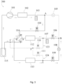
- Fig. 3 shows a circulation path when the refrigeration system 100 shown in Fig. 1A is set to the second operating system.
- hot water can be supplied to the user end via the first heat exchanger 102, and hot water for air conditioning/heating can be supplied to the user end via the second heat exchanger 112.
- a second series-connected path 300 can be formed.
- the third disconnection device 104, fourth disconnection device 106, fifth disconnection device 109 and first throttle valve 108 are in an open state; the second throttle valve 105, first disconnection device 110 and second disconnection device 111 are in a closed state; and in the path switching device 114, the second pair of controllable paths are connected and the first pair of controllable paths are disconnected.
- the arrows in Fig. 3 show the flow direction of refrigerant in the second series-connected path 300.
- the second series-connected path 300 can sequentially connect the compressor 101, first heat exchanger 102, first liquid reservoir 103, third disconnection device 104, third controllable path mq, third heat exchanger 113, fifth disconnection device 109, first throttle valve 108, fourth disconnection device 106, second liquid reservoir 107, second heat exchanger 112, fourth controllable path np and gas/liquid separator 115.
- the first heat exchanger 102, second heat exchanger 112 and third heat exchanger 113 are all in an operational state.
- the first heat exchanger 102 and third heat exchanger 113 act as condensers, and the second heat exchanger 112 acts as an evaporator.
- Fig. 4 shows a circulation path when the refrigeration system 100 shown in Fig. 1A is set to the third operating system.
- hot water can be supplied to the user end via the first heat exchanger 102.
- a third series-connected path 400 can be formed.
- the fifth disconnection device 109, first throttle valve 108 and second throttle valve 105 are in an open state; the first disconnection device 110, second disconnection device 111, third disconnection device 104 and fourth disconnection device 106 are in a closed state; and in the path switching device 114, the first pair of controllable paths are connected and the second pair of controllable paths are disconnected.
- the arrows in Fig. 4 show the flow direction of refrigerant in the third series-connected path 400.
- the third series-connected path 400 sequentially connects the compressor 101, first heat exchanger 102, first liquid reservoir 103, second throttle valve 105, first throttle valve 108, fifth disconnection device 109, third heat exchanger 113, second controllable path pq and gas/liquid separator 115.
- the first heat exchanger 102 acts as a condenser
- the third heat exchanger 113 acts as an evaporator
- the second heat exchanger 112 is in a non-operational state.
- the statement “the second heat exchanger 112 is in a non-operational state” means: refrigerant can flow through the second heat exchanger 112, but refrigerant in the second heat exchanger 112 is not used for the heating or cooling of water supplied to the user end.
- the temperature of a medium in the second heat exchanger 112 i.e. water that participates in heat exchange in the second heat exchanger 112 and is supplied to the user end
- a medium in the second heat exchanger 112 i.e. water that participates in heat exchange in the second heat exchanger 112 and is supplied to the user end
- the pressure of the operating system low-pressure side (i.e. at point C) is detected by means of the pressure detection device 156, and the temperature in the second heat exchanger 112 is detected by means of the first temperature detection device 152.
- Saturation temperatures corresponding to different pressures of refrigerant are stored in the control device 144; thus, based on the pressure value detected by the pressure detection device 156, the saturation temperature of the refrigerant at this pressure can be obtained.
- the saturation temperature of refrigerant corresponding to the pressure of the operating system low-pressure side i.e. at point C
- the pressure of the operating system low-pressure side i.e.
- the control device 144 will open the first disconnection device 110, thus connecting the first discharge path 123, and thereby enabling the refrigerant that has accumulated inside the second heat exchanger 112 to migrate towards the operating system low-pressure side of the refrigeration system 100 due to the pressure difference.
- the saturation temperature of refrigerant corresponding to the pressure of the operating system low-pressure side i.e. at point C
- the control device 144 will reduce the degree of opening of the second throttle valve 105 and/or first throttle valve 108, such that the pressure of the operating system low-pressure side (i.e.
- the control device 144 then opens the first disconnection device 110, thus connecting the first discharge path 123, and thereby enabling the refrigerant that has accumulated inside the second heat exchanger 112 to migrate towards the operating system low-pressure side due to the pressure difference.
- the pressure of the operating system low-pressure side i.e.
- the control device 144 disconnects the first discharge path 123 by closing the first disconnection device 110.
- the control device 144 closes the first disconnection device 110 when the first discharge path 123 has been connected (i.e. refrigerant inside the second heat exchanger 112 has been discharged) for 2 - 5 minutes.
- the arrangement described above enables refrigerant that has accumulated inside the second heat exchanger 112 to migrate into the third series-connected path 400 of the third operating system, thereby avoiding shortage of refrigerant in the operating system when the refrigeration system 100 is running in the third operating system.
- the first operating system and third operating system can be implemented by opening and closing the third disconnection device 104, fourth disconnection device 106 and second throttle valve 105.
- the third disconnection device 104 and fourth disconnection device 106 are closed and the second throttle valve 105 is opened, such that the sequential connection of the compressor 101, first heat exchanger 102, first liquid reservoir 103, second throttle valve 105, first throttle valve 108, fifth disconnection device 109, third heat exchanger 113, second controllable path pq and gas/liquid separator 115 is maintained while the second heat exchanger 112 is separated from the first series-connected path 200, thereby switching the first series-connected path 200 to the third series-connected path 400.
- Fig. 5 shows a circulation path when the refrigeration system 100 shown in Fig. 1A is set to the fourth operating system.
- hot water can be supplied to the user end via the first heat exchanger 102, and cooling water for air conditioning/cooling can be supplied to the user end via the second heat exchanger 112.
- a fourth series-connected path 500 can be formed.
- the fourth disconnection device 106 and second throttle valve 105 are in an open state; the third disconnection device 104, fifth disconnection device 109, first disconnection device 110, second disconnection device 111 and first throttle valve 108 are in a closed state; and in the path switching device 114, the second pair of controllable paths are connected and the first pair of controllable paths are disconnected.
- the arrows in Fig. 5 show the flow direction of refrigerant in the fourth series-connected path 500.
- the fourth series-connected path 500 can sequentially connect the compressor 101, first heat exchanger 102, first liquid reservoir 103, second throttle valve 105, fourth disconnection device 106, second liquid reservoir 107, second heat exchanger 112, fourth controllable path np and gas/liquid separator 115.
- the first heat exchanger 102 acts as a condenser
- the second heat exchanger 112 acts as an evaporator
- the third heat exchanger 113 is in a non-operational state.
- the statement “the third heat exchanger 113 is in a non-operational state” means: refrigerant can flow through the third heat exchanger 113, but refrigerant in the third heat exchanger 113 is not used for the heating or cooling of external air.
- the temperature of a medium in the third heat exchanger 113 i.e. air that participates in heat exchange in the third heat exchanger 113 will gradually approach the temperature of the environment in which the third heat exchanger 113 is located.
- the pressure of the operating system low-pressure side (i.e. at point C) is detected by means of the pressure detection device 156, and the temperature in the third heat exchanger 113 is detected by means of the second temperature detection device 154.
- Saturation temperatures corresponding to different pressures of refrigerant are stored in the control device 144; thus, based on the pressure value detected by the pressure detection device 156, the saturation temperature of the refrigerant at this pressure can be obtained.
- the saturation temperature of refrigerant corresponding to the pressure of the operating system low-pressure side i.e. at point C
- the pressure of the operating system low-pressure side i.e.
- the control device 144 will open the second disconnection device 111, thus connecting the second discharge path 124, and thereby enabling the refrigerant that has accumulated inside the third heat exchanger 113 to migrate towards the operating system low-pressure side due to the pressure difference.
- the saturation temperature of refrigerant corresponding to the pressure of the operating system low-pressure side i.e. at point C
- the control device 144 will reduce the degree of opening of the second throttle valve 105, such that the pressure of the operating system low-pressure side (i.e.
- the control device 144 then opens the second disconnection device 111, thus connecting the second discharge path 124, and thereby enabling the refrigerant that has accumulated inside the third heat exchanger 113 to migrate towards the operating system low-pressure side due to the pressure difference.
- the pressure of the operating system low-pressure side i.e.
- point C is the same as the pressure in the third heat exchanger 113, i.e. the saturation temperature corresponding to the pressure of the operating system low-pressure side (i.e. point C) is the same as the temperature in the third heat exchanger 113; at this time, the control device 144 disconnects the second discharge path 124 by closing the second disconnection device 111. In some embodiments, the control device 144 closes the second disconnection device 111 when the second discharge path 124 has been connected (i.e. refrigerant inside the third heat exchanger 113 has been discharged) for 2 - 5 minutes.
- the arrangement described above enables refrigerant that has accumulated inside the third heat exchanger 113 to migrate into the fourth series-connected path 500 of the fourth operating system, thereby avoiding shortage of refrigerant in the operating system when the refrigeration system 100 is running in the fourth operating system.
- the second operating system and fourth operating system can be implemented by opening and closing the third disconnection device 104, fifth disconnection device 109 and second throttle valve 105.
- the third disconnection device 104 and fifth disconnection device 109 are closed and the second throttle valve 105 is opened, such that the sequential connection of the compressor 101, first heat exchanger 102, first liquid reservoir 103, second throttle valve 105, fourth disconnection device 106, second liquid reservoir 107, second heat exchanger 112, fourth controllable path np and gas/liquid separator 115 is maintained while the third heat exchanger 113 is separated from the second series-connected path 300, thereby switching the second series-connected path 300 to the fourth series-connected path 500.
- the fifth disconnection device 109 and first throttle valve 108 are provided in the refrigeration system 100, due to the fact that the fifth disconnection device 109 and first throttle valve 108 are connected in series and the first throttle valve 108 is configured such that the degree of opening thereof (i.e. the flow rate through the first throttle valve 108) can be controlled, it is also possible to omit the fifth disconnection device 109, and realize the opening and closing functions of the fifth disconnection device 109 through the opening and closing of the first throttle valve 108.
- Fig. 6A shows a refrigeration system 600 in a second embodiment of the present invention.
- the refrigeration system 600 comprises a compressor 617, a first heat exchanger 603, a second heat exchanger 604, a third heat exchanger 615, a first throttle valve 609, a second throttle valve 612, a first liquid reservoir 605, a second liquid reservoir 606 and a gas/liquid separator 618.
- the compressor 617 is configured to compress refrigerant to a high-temperature, high-pressure fluid.
- the first heat exchanger 603 and second heat exchanger 604 are both water-side heat exchangers.
- the third heat exchanger 615 in the present embodiment is a wind-side heat exchanger. When refrigerant flows through the third heat exchanger 615, it can exchange heat with external air via the third heat exchanger 615, so that the temperature of the refrigerant rises or falls.
- the first liquid reservoir 605 and second liquid reservoir 606 are configured to store refrigerant in the refrigeration system 600.
- the gas/liquid separator 618 is configured to separate gaseous refrigerant and liquid refrigerant entering the gas/liquid separator 618, so that the refrigerant which flows out of the gas/liquid separator 618 is gaseous refrigerant.
- the refrigeration system 600 further comprises a switch structure, configured to enable the refrigeration system 600 to switch among different operating systems.
- the switch structure comprises a first switching assembly 601, a second switching assembly 602, a sixth disconnection device 607 and a seventh disconnection device 613.
- the sixth disconnection device 607 and seventh disconnection device 613 are solenoid valves.
- the first switching assembly 601 is a three-way valve having three ports b', c' and d', and the three-way valve has a first three-way controllable path b'c' and a second three-way controllable path b'd'.
- the first three-way controllable path b'c' can connect ports b' and c'
- the second three-way controllable path b'd' can connect ports b' and d'.
- the second switching assembly 602 is a four-way valve having a total of four ports, specifically a first port m', a second port n', a third port p' and a fourth port q'. Moreover, the four-way valve is provided with a first set of control paths and a second set of control paths.
- the first set of control paths comprises a first control path m'n' and a second control path p'q'.
- the first control path m'n' can connect the first port m' with the second port n'
- the second control path p'q' can connect the third port p' with the fourth port q' .
- the second set of control paths comprises a third control path m'q' and a fourth control path n'p' .
- the third control path m'q' can connect the first port m' with the fourth port q'
- the fourth control path n'p' can connect the second port n' with the third port p'.
- the refrigeration system 600 further comprises a first one-way valve 610 and a second one-way valve 611, for ensuring that refrigerant flows in a single direction in circulation pipelines in which the first one-way valve 610 and second one-way valve 611 are located.
- the various components mentioned above are connected by connecting pipelines to form the refrigeration system 600.
- the port c' of the first switching assembly 601 is connected to an end e' of the first heat exchanger 603
- another end f' of the first heat exchanger 603 is connected to an end g' of the first throttle valve 609
- another end h' of the first throttle valve 609 is connected to an inlet end of the first one-way valve 610
- an outlet end of the first one-way valve 610 is connected to an end l' of the sixth disconnection device 607
- another end k' of the sixth disconnection device 607 is connected to an end j' of the second heat exchanger 604
- another end i' of the second heat exchanger 604 is connected to the first port m' of the second switching assembly 602.
- the first liquid reservoir 605 is disposed on the connecting pipeline between the other end f' of the first heat exchanger 603 and the end g' of the first throttle valve 609.
- the second liquid reservoir 606 is disposed on the connecting pipeline between the other end k' of the sixth disconnection device 607 and the end j' of the second heat exchanger 604.
- the port b' of the first switching assembly 601 is connected to a gas discharge end a' of the compressor 617, a gas suction end a" of the compressor 617 is in communication with the second port n' of the second switching assembly 602, and the gas/liquid separator 115 is disposed between connecting pipelines of the gas suction end a" of the compressor 617 and the second port n' of the second switching assembly 602.
- the third port p' of the second switching assembly 602 is connected to an end r' of the third heat exchanger 615, another end s' of the third heat exchanger 615 is connected to an end u' of the seventh disconnection device 613, another end v' of the seventh disconnection device 613 is connected to an outlet end of the second one-way valve 611, and an inlet end of the second one-way valve 611 is connected at a connection point M between the other end h' of the first throttle valve 609 and the inlet end of the first one-way valve 610.
- An end x' of the second throttle valve 612 is connected at a connection point N between the outlet end of the first one-way valve 610 and the end l' of the sixth disconnection device 607; another end y' of the second throttle valve 612 is connected at a connection point O between the other end v' of the seventh disconnection device 613 and the outlet end of the second one-way valve 611.
- the fourth port q' of the second switching assembly 602 is connected to the port d' of the first switching assembly 601.
- the refrigeration system 600 further comprises a discharge path.
- the discharge path comprises a first discharge path 623 and a second discharge path 624.
- the first discharge path 623 and second discharge path 624 can be controllably connected or disconnected by a discharge switch device.
- the discharge switch device comprises a first disconnection device 608 and a second disconnection device 614.
- the first disconnection device 608 and second disconnection device 614 are solenoid valves.
- One end of the first discharge path 623 is connected at a connection point P between the second liquid reservoir 606 and the sixth disconnection device 607; another end of the first discharge path 623 is connected at a connection point Q between the gas/liquid separator 618 and the second port n' of the second switching assembly 602.
- the first disconnection device 608 is disposed on the first discharge path 623.
- One end of the second discharge path 624 is connected at a connection point R between the third heat exchanger 615 and the seventh disconnection device 613; another end of the second discharge path 624 is connected at a connection point S between the connection point Q and the first disconnection device 608.
- the second disconnection device 614 is disposed on the second discharge path 624.
- the refrigeration system 600 shown in Fig. 6A can realize four operating systems, comprising a fifth operating system, a sixth operating system, a seventh operating system and an eighth operating system, through the cooperation of the switch structure, the first throttle valve 609 and the second throttle valve 612.
- the refrigeration system 600 When the refrigeration system 600 is set to the fifth operating system and the sixth operating system, the second three-way controllable path b'd' in the first switching assembly 601 is connected and the first three-way controllable path b'c' is disconnected.
- the refrigeration system 600 is set to the seventh operating system and the eighth operating system, the first three-way controllable path b'c' in the first switching assembly 601 is connected and the second three-way controllable path b'd' is disconnected.
- the refrigeration system 600 When the refrigeration system 600 is set to the fifth operating system and the seventh operating system, the first set of control paths in the second switching assembly 602 are connected and the second set of control paths are disconnected. When the refrigeration system 600 is set to the sixth operating system and the eighth operating system, the second set of control paths in the second switching assembly 602 are connected and the first set of control paths are disconnected.
- Fig. 6B is a schematic diagram of control components in the refrigeration system 600 shown in Fig. 6A .
- the refrigeration system 600 further comprises a first temperature detection device 652, a second temperature detection device 654 and a pressure detection device 656.
- the first temperature detection device 652 is disposed in the second heat exchanger 604, and configured to detect the temperature in the second heat exchanger 604.
- the second temperature detection device 654 is disposed in the third heat exchanger 615, and configured to detect the temperature in the third heat exchanger 615.
- the pressure detection device 656 is disposed at connection point Q, and configured to detect a pressure of an operating system low-pressure side of the refrigeration system 600.
- the refrigeration system 600 further comprises a control device 644.
- the control device 644 is in communicative connection with the first throttle valve 609, second throttle valve 612, first switching assembly 601, second switching assembly 602, sixth disconnection device 607, seventh disconnection device 613, first disconnection device 608, second disconnection device 614, pressure detection device 656, first temperature detection device 652 and second temperature detection device 654.
- the control device 644 is configured to be able to control the degree of opening of the first throttle valve 609 and second throttle valve 612 according to the different operating systems of the refrigeration system 600, and thereby control a pressure drop of refrigerant flowing through the first throttle valve 609 and second throttle valve 612.
- the control device 644 is configured to be able to control the switching of different paths in the first switching assembly 601 and second switching assembly 602 according to the different operating systems of the refrigeration system 600, and control the opening or closing of the sixth disconnection device 607 and the seventh disconnection device 613.
- the control device 644 is further configured to be able to control the opening or closing of the first disconnection device 608 and second disconnection device 614 according to a pressure value provided by the pressure detection device 656 and temperature values provided by the first temperature detection device 652 and second temperature detection device 654, and thereby control the connection and disconnection of the first discharge path 623 and second discharge path 624.
- Fig. 7 shows a circulation path when the refrigeration system 600 shown in Fig. 6A is set to the fifth operating system.
- cooling water for air conditioning/refrigeration can be supplied to the user end via the second heat exchanger 604.
- a fifth series-connected path 700 can be formed.
- the sixth disconnection device 607, seventh disconnection device 613 and second throttle valve 612 are in an open state; the first disconnection device 608 and second disconnection device 614 are in a closed state; the second three-way controllable path b'd' in the first switching assembly 601 is connected and the first three-way controllable path b'c' is disconnected; and the first set of control paths in the second switching assembly 602 are connected and the second set of control paths are disconnected.
- the first one-way valve 610 and second one-way valve 611 can prevent the flow of fluid from the outlet end of the one-way valve towards the inlet end.
- the arrows in Fig. 7 show the flow direction of refrigerant in the fifth series-connected path 700.
- the fifth series-connected path 700 sequentially connects the compressor 617, second three-way controllable path b'd', second controllable path p'q', third heat exchanger 615, seventh disconnection device 613, second throttle valve 612, sixth disconnection device 607, second liquid reservoir 606, second heat exchanger 604, first controllable path m'n' and gas/liquid separator 618.
- the third heat exchanger 615 acts as a condenser
- the second heat exchanger 604 acts as an evaporator
- the first heat exchanger 603 is in a non-operational state.
- Fig. 8 shows a circulation path when the refrigeration system 600 shown in Fig. 6A is set to the sixth operating system.
- the refrigeration system 600 is set to the sixth operating system, hot water for air conditioning/heating can be supplied to the user end via the second heat exchanger 604.
- a sixth series-connected path 800 can be formed.
- the sixth disconnection device 607, seventh disconnection device 613 and second throttle valve 612 are in an open state; the first disconnection device 608 and second disconnection device 614 are in a closed state; the second three-way controllable path b'd' in the first switching assembly 601 is connected and the first three-way controllable path b'c' is disconnected; and the second set of control paths in the second switching assembly 602 are connected and the first set of control paths are disconnected.
- the first one-way valve 610 and second one-way valve 611 can prevent the flow of fluid from the outlet end of the one-way valve towards the inlet end.
- the arrows in Fig. 8 show the flow direction of refrigerant in the sixth series-connected path 800.
- the sixth series-connected path 800 sequentially connects the compressor 617, the second three-way controllable path b'd', the third controllable path m'q', the second heat exchanger 604, the second liquid reservoir 606, the sixth disconnection device 607, the second throttle valve 612, the seventh disconnection device 613, the third heat exchanger 615, the fourth control path n'p' and the gas/liquid separator 618.
- the second heat exchanger 604 acts as a condenser
- the third heat exchanger 615 acts as an evaporator
- the first heat exchanger 603 is in a non-operational state.
- the first heat exchanger 603 When the refrigeration system 600 is set to the fifth operating system or sixth operating system, the first heat exchanger 603 is in a non-operational state.
- the statement "the first heat exchanger 603 is in a non-operational state” means: refrigerant can flow through the first heat exchanger 603, but refrigerant in the first heat exchanger 603 is not used for the heating or cooling of water supplied to the user end. However, since the first heat exchanger 603 is used to supply hot water to the user side, the temperature of the medium of the first heat exchanger 603 is high.
- the temperature of the medium in the first heat exchanger 603 is higher than a saturation temperature corresponding to the pressure inside the first heat exchanger 603; thus, there is no condensation and consequent accumulation of refrigerant in the first heat exchanger 603. Therefore, in an embodiment of the present invention, no discharge path is provided between the first heat exchanger 603 in the refrigeration system 600 and the operating system low-pressure side of the refrigeration system 600.
- the fifth operating system and sixth operating system can be implemented by path switching in the second switching assembly 602.
- the fifth series-connected path 700 can be switched to the sixth series-connected path 800 by switching the second switching assembly 602 from a configuration in which the first pair of controllable paths are connected, to a configuration in which the second pair of controllable paths are connected.
- first one-way valve 610 and second one-way valve 611 are provided in the refrigeration system 600 to control the flow of refrigerant so as to form the fifth series-connected path 700 and sixth series-connected path 800, those skilled in the art will understand that another device such as a solenoid valve or pump could also be used to realize the connection and disconnection functions of the first one-way valve 610 and second one-way valve 611.
- Fig. 9 shows a circulation path when the refrigeration system 600 shown in Fig. 6A is set to the seventh operating system.
- hot water can be supplied to the user end via the first heat exchanger 603, and cooling water for air conditioning/refrigeration can be supplied to the user end via the second heat exchanger 604.
- a seventh series-connected path 900 can be formed.
- the sixth disconnection device 607 and first throttle valve 609 are in an open state; the second throttle valve 612, seventh disconnection device 613, first disconnection device 608 and second disconnection device 614 are in a closed state.
- the first switching assembly 601 the first three-way controllable path b'c' is connected and the second three-way controllable path b'd' is disconnected; and in the second switching assembly 602, the first set of control paths are connected and the second set of control paths are disconnected.
- the arrows in Fig. 9 show the flow direction of refrigerant in the seventh series-connected path 900.
- the seventh series-connected path 900 sequentially connects the compressor 617, first three-way controllable path b'c', first heat exchanger 603, first liquid reservoir 605, first throttle valve 609, first one-way valve 610, sixth disconnection device 607, second liquid reservoir 606, second heat exchanger 604, first control path m'n' and gas/liquid separator 618.
- the first heat exchanger 603 acts as a condenser
- the second heat exchanger 604 acts as an evaporator
- the third heat exchanger 615 is in a non-operational state.
- the statement "the third heat exchanger 615 is in a non-operational state" means: refrigerant can flow through the third heat exchanger 615, but refrigerant in the third heat exchanger 615 is not used for the heating or cooling of external air.
- the temperature of a medium in the third heat exchanger 615 i.e. air that participates in heat exchange in the third heat exchanger 615) will gradually approach the temperature of the environment in which the third heat exchanger 615 is located.
- the pressure of the operating system low-pressure side (i.e. at point Q) is detected by means of the pressure detection device 656, and the temperature in the third heat exchanger 615 is detected by means of the second temperature detection device 654.
- Saturation temperatures corresponding to different pressures of refrigerant are stored in the control device 644; thus, based on the pressure value detected by the pressure detection device 656, the saturation temperature of the refrigerant at this pressure can be obtained.
- the saturation temperature of refrigerant corresponding to the pressure of the operating system low-pressure side (i.e. at point Q) is lower than the temperature in the third heat exchanger 615 as detected by the second temperature detection device 654, the pressure of the operating system low-pressure side (i.e.
- the control device 644 will open the second disconnection device 614, thus connecting the second discharge path 624, and thereby enabling the refrigerant that has accumulated inside the third heat exchanger 615 to migrate towards the operating system low-pressure side of the refrigeration system 600 due to the pressure difference.
- the saturation temperature of refrigerant corresponding to the pressure of the operating system low-pressure side i.e. at point Q
- the control device 644 will reduce the degree of opening of the first throttle valve 609, such that the pressure of the operating system low-pressure side (i.e.
- the control device 644 then opens the second disconnection device 614, thus connecting the second discharge path 624, and thereby enabling the refrigerant that has accumulated inside the third heat exchanger 615 to migrate towards the operating system low-pressure side. After discharge has taken place through the second discharge path 624 for a period of time, the pressure of the operating system low-pressure side (i.e.
- the control device 644 disconnects the second discharge path 624 by closing the second disconnection device 614.
- the control device 644 closes the second disconnection device 614 when the second discharge path 624 has been connected (i.e. refrigerant inside the third heat exchanger 615 has been discharged) for 2 - 5 minutes.
- the arrangement described above enables refrigerant that has accumulated inside the third heat exchanger 615 to migrate into the seventh series-connected path 900 of the seventh operating system, thereby avoiding shortage of refrigerant in the operating system when the refrigeration system 600 is running in the seventh operating system.
- Fig. 10 shows a circulation path when the refrigeration system 600 shown in Fig. 6A is set to the eighth operating system.
- hot water can be supplied to the user end via the first heat exchanger 603.
- an eighth series-connected path 1000 can be formed.
- the seventh disconnection device 613 and first throttle valve 609 are in an open state; the second throttle valve 612, sixth disconnection device 607, first disconnection device 608 and second disconnection device 614 are in a closed state.
- the first switching assembly 601 the first three-way controllable path b'c' is connected and the second three-way controllable path b'd' is disconnected; and in the second switching assembly 602, the second set of control paths are connected and the first set of control paths are disconnected.
- the arrows in Fig. 10 show the flow direction of refrigerant in the eighth series-connected path 1000.
- the eighth series-connected path 1000 sequentially connects the compressor 617, first three-way controllable path b'c', first heat exchanger 603, first liquid reservoir 605, first throttle valve 609, second one-way valve 611, seventh disconnection device 613, third heat exchanger 615, fourth control path n'p' and gas/liquid separator 618.
- the first heat exchanger 603 acts as a condenser
- the third heat exchanger 615 acts as an evaporator
- the second heat exchanger 604 is in a non-operational state.
- the second heat exchanger 604 is in a non-operational state
- refrigerant can flow through the second heat exchanger 604, but refrigerant in the second heat exchanger 604 is not used for the heating or cooling of water supplied to the user end.
- the temperature of a medium in the second heat exchanger 604 i.e. water that participates in heat exchange in the second heat exchanger 604 will gradually approach the temperature of the environment in which the second heat exchanger 604 is located.
- the pressure of the operating system low-pressure side (i.e. at point Q) is detected by means of the pressure detection device 656, and the temperature in the second heat exchanger 604 is detected by means of the first temperature detection device 652.
- Saturation temperatures corresponding to different pressures of refrigerant are stored in the control device 644; thus, based on the pressure value detected by the pressure detection device 656, the saturation temperature of the refrigerant at this pressure can be obtained.
- the saturation temperature of refrigerant corresponding to the pressure of the operating system low-pressure side (i.e. at point Q) is lower than the temperature in the second heat exchanger 604 as detected by the first temperature detection device 652, the pressure of the operating system low-pressure side (i.e.
- the control device 644 will open the first disconnection device 608, thus connecting the first discharge path 623, and thereby enabling the refrigerant that has accumulated inside the second heat exchanger 604 to migrate towards the operating system low-pressure side due to the pressure difference.
- the saturation temperature of refrigerant corresponding to the pressure of the operating system low-pressure side i.e. at point Q
- the control device 644 will reduce the degree of opening of the first throttle valve 609, such that the pressure of the operating system low-pressure side drops, so that the pressure of the operating system low-pressure side (i.e.
- the control device 644 then opens the first disconnection device 608, thus connecting the first discharge path 623, and thereby enabling the refrigerant that has accumulated inside the second heat exchanger 604 to migrate towards the operating system low-pressure side.
- the pressure of the operating system low-pressure side is the same as the pressure in the second heat exchanger 604, i.e.
- the saturation temperature corresponding to the pressure of the operating system low-pressure side (i.e. at point Q) is the same as the temperature in the second heat exchanger 604; at this time, the control device 644 disconnects the first discharge path 623 by closing the first disconnection device 608. In some embodiments, the control device 644 closes the first disconnection device 608 when the first discharge path 623 has been connected (i.e. refrigerant inside the second heat exchanger 604 has been discharged) for 2 - 5 minutes.
- the arrangement described above enables refrigerant that has accumulated inside the second heat exchanger 604 to migrate into the eighth series-connected path 1000 of the eighth operating system, thereby avoiding shortage of refrigerant in the operating system when the refrigeration system 600 is running in the eighth operating system.
- the seventh operating system and eighth operating system can be implemented by path switching in the second switching assembly 602 and connection or disconnection of the sixth disconnection device 607 and seventh disconnection device 613.
- the seventh series-connected path 900 can be switched to the eighth series-connected path 1000 by switching the second switching assembly 602 from a configuration in which the first set of control paths are connected, to a configuration in which the second set of control paths are connected, closing the sixth disconnection device 607 and opening the seventh disconnection device 613.
- first heat exchangers 102, 603 and second heat exchangers 112, 604 in the refrigeration system 100 and refrigeration system 600 in some embodiments are water-side heat exchangers, and the third heat exchangers 113, 615 are wind-side heat exchangers, those skilled in the art could configure them as different types of heat exchangers according to actual needs.
- first switching assembly 601 is not limited to using a three-way valve
- path switching device 114 and second switching assembly 602 are not limited to using four-way valves
- first disconnection device 110, second disconnection device 111, third disconnection device 104, fourth disconnection device 106, fifth disconnection device 109, sixth disconnection device 607 and seventh disconnection device 613 are not limited to using solenoid valves, but could be configured as various types of device capable of achieving connection and disconnection, e.g. a pump, etc., according to actual needs.
- gas/liquid separator and liquid reservoir are provided in some embodiments, it is also possible for the gas/liquid separator and/or the liquid reservoir not to be provided.
- the discharge path could also connect the non-operational heat exchanger to another position at the operating system low-pressure side, for example, connect the non-operational heat exchanger directly to the gas suction end of the compressor.
Landscapes
- Engineering & Computer Science (AREA)
- Physics & Mathematics (AREA)
- Mechanical Engineering (AREA)
- Thermal Sciences (AREA)
- General Engineering & Computer Science (AREA)
- Compression-Type Refrigeration Machines With Reversible Cycles (AREA)
- Devices That Are Associated With Refrigeration Equipment (AREA)
Claims (12)
- Système de réfrigération, dans lequel le système de réfrigération comprend :- des composants de système de réfrigération, comprenant un compresseur (101 ; 617), un premier échangeur de chaleur (102 ; 603), un deuxième échangeur de chaleur (112 ; 604), un troisième échangeur de chaleur (113 ; 615), un premier robinet d'étranglement (108 ; 609) et un deuxième robinet d'étranglement (105 ; 612) ;- des conduites de connexion, capables de connecter tous les composants de système de réfrigération susmentionnés, et capables de combiner les composants de système de réfrigération de différentes manières pour former de multiples systèmes d'exploitation différents ;- une structure de commutation, configurée pour être capable de connecter les conduites de connexion afin de former un système d'exploitation, et capable de sélectionner, parmi le premier échangeur de chaleur (102 ; 603), le deuxième échangeur de chaleur (112 ; 604) et le troisième échangeur de chaleur (113 ; 615), deux échangeurs de chaleur pour une connexion dans ledit système d'exploitation, et d'isoler un échangeur de chaleur non sélectionné parmi ledit système d'exploitation ;- un trajet de décharge (123, 124 ; 623, 624), le trajet de décharge (123, 124 ; 623, 624) étant agencé entre l'échangeur de chaleur non sélectionné et un côté basse pression dudit système d'exploitation, et capable de connecter de façon commandée l'échangeur de chaleur non sélectionné au côté basse pression dudit système d'exploitation, le trajet de décharge (123, 124 ; 623, 624) comprenant un dispositif de commutation de décharge pour commander la connexion et la déconnexion du trajet de décharge (123, 124 ; 623, 624) ; un dispositif de commande (144 ; 644), le dispositif de commande (144 ; 644) étant en connexion de communication avec le dispositif de commutation de décharge, dans lequel le dispositif de commande est configuré pour connecter le trajet de décharge entre l'échangeur de chaleur non sélectionné et le côté basse pression (C ; Q) dudit système d'exploitation lorsque la température d'un milieu, qui subit un transfert de chaleur avec un fluide frigorigène, dans l'échangeur de chaleur non sélectionné ou la température d'un environnement dans lequel est situé l'échangeur de chaleur non sélectionné est inférieure à une température de saturation dans l'échangeur de chaleur non sélectionné.
- Système de réfrigération selon la revendication 1, dans lequel :- lorsque le trajet de décharge (123, 124 ; 623, 624) est agencé entre l'échangeur de chaleur non sélectionné et le côté basse pression (C ; Q) dudit système d'exploitation, le système de réfrigération est configuré de telle sorte que :(i) lorsqu'une pression du côté basse pression (C ; Q) dudit système d'exploitation est inférieure à une pression dans l'échangeur de chaleur non sélectionné, le trajet de décharge (123, 124 ; 623, 624) est connecté de telle sorte que le fluide frigorigène dans l'échangeur de chaleur non sélectionné s'écoule dans le côté basse pression (C ; Q) dudit système d'exploitation ;(ii) lorsque la pression du côté basse pression (C ; Q) dudit système d'exploitation n'est pas inférieure à la pression dans l'échangeur de chaleur non sélectionné, le premier robinet d'étranglement (108 ; 609) ou le deuxième robinet d'étranglement (105 ; 612) est d'abord ajusté pour baisser la pression du côté basse pression (C ; Q) dudit système d'exploitation, de telle sorte que le fluide frigorigène dans l'échangeur de chaleur non sélectionné est apte à s'écouler dans le côté basse pression (C ; Q) dudit système d'exploitation, le trajet de décharge (123, 124 ; 623, 624) est ensuite connecté de telle sorte que le fluide frigorigène dans l'échangeur de chaleur non sélectionné s'écoule dans le côté basse pression (C ; Q) dudit système d'exploitation, et le trajet de décharge (123, 124 ; 623, 624) est déconnecté lorsqu'une décharge a eu lieu pendant une période de temps.
- Système de réfrigération selon la revendication 1, dans lequel :- le dispositif de commutation de décharge comprend un premier dispositif de déconnexion (110 ; 608) et un deuxième dispositif de déconnexion (111 ; 614) ; le premier dispositif de déconnexion (110 ; 608) est configuré pour connecter le deuxième échangeur de chaleur (112 ; 604) à ou déconnecter le deuxième échangeur de chaleur d'un côté basse pression (C ; Q) d'un système d'exploitation formé par le compresseur (101 ; 617), le premier échangeur de chaleur (102 ; 603), le troisième échangeur de chaleur (113 ; 615) et soit l'un, soit les deux parmi le premier robinet d'étranglement (108 ; 609) et le deuxième robinet d'étranglement (105 ; 612) ; le deuxième dispositif de déconnexion (111 ; 614) est configuré pour connecter le troisième échangeur de chaleur (113 ; 615) à ou déconnecter le troisième échangeur de chaleur d'un côté basse pression (C ; Q) d'un système d'exploitation formé par le compresseur (101 ; 617), le premier échangeur de chaleur (102 ; 603), le deuxième échangeur de chaleur (112 ; 604) et soit l'un, soit les deux parmi le premier robinet d'étranglement (108 ; 609) et le deuxième robinet d'étranglement (105 ; 612).
- Système de réfrigération selon la revendication 3,
dans lequel le système de réfrigération comprend en outre :- un dispositif de détection de pression, configuré pour être capable de détecter la pression du côté basse pression (C ; Q) du système d'exploitation et de fournir un signal de détection de pression ;- un dispositif de détection de température, configuré pour être capable de détecter une température dans l'échangeur de chaleur non sélectionné et de fournir un signal de détection de température. - Système de réfrigération selon la revendication 4,
dans lequel le système de réfrigération comprend en outre :- le dispositif de commande (144 ; 644) configuré pour commander la connexion et la déconnexion du trajet de décharge (123, 124 ; 623, 624) selon le signal de détection de pression détecté par le dispositif de détection de pression et le signal de détection de température détecté par le dispositif de détection de température. - Système de réfrigération selon la revendication 2, dans lequel :- le système d'exploitation comprend un premier système d'exploitation et un deuxième système d'exploitation ;- le premier système d'exploitation est formé par connexion d'un premier trajet connecté en série (200), le premier trajet connecté en série (200) connectant en série en séquence le compresseur (101), le premier échangeur de chaleur (102), le deuxième échangeur de chaleur (112), le premier robinet d'étranglement (108) et le troisième échangeur de chaleur (113), dans lequel le premier échangeur de chaleur (102) et le deuxième échangeur de chaleur (112) agissent en tant que condenseurs, et le troisième échangeur de chaleur (113) agit en tant qu'évaporateur ;- le deuxième système d'exploitation est formé par connexion d'un deuxième trajet connecté en série (300), le deuxième trajet connecté en série (300) connectant en série en séquence le compresseur (101), le premier échangeur de chaleur (102), le troisième échangeur de chaleur (113), le premier robinet d'étranglement (108) et le deuxième échangeur de chaleur (112), dans lequel le premier échangeur de chaleur (102) et le troisième échangeur de chaleur (113) agissent en tant que condenseurs, et le deuxième échangeur de chaleur (112) agit en tant qu'évaporateur ;- la structure de commutation comprend un dispositif de commutation de trajet (114), et le premier système d'exploitation et le deuxième système d'exploitation peuvent être commutés de façon sélective au moyen du dispositif de commutation de trajet (114).
- Système de réfrigération selon la revendication 6, dans lequel :- la structure de commutation comprend un troisième dispositif de déconnexion (104), un quatrième dispositif de déconnexion (106) et un cinquième dispositif de déconnexion (109) ; le troisième dispositif de déconnexion (104) est connecté entre le premier échangeur de chaleur (102) et le dispositif de commutation de trajet (114) ; le quatrième dispositif de déconnexion (106) est connecté entre le deuxième échangeur de chaleur (112) et le premier robinet d'étranglement (108) ; le cinquième dispositif de déconnexion (109) est connecté entre le troisième échangeur de chaleur (113) et le premier robinet d'étranglement (108) ;- le deuxième robinet d'étranglement (105) a une extrémité connectée entre le premier échangeur de chaleur (102) et le troisième dispositif de déconnexion (104), et une autre extrémité connectée entre le quatrième dispositif de déconnexion (106) et le premier robinet d'étranglement (108) ;- le système d'exploitation comprend en outre un troisième système d'exploitation et un quatrième système d'exploitation ;- le troisième système d'exploitation est formé par un troisième trajet connecté en série (400), et lorsque le troisième système d'exploitation est formé, le troisième trajet connecté en série (400) est configuré de telle sorte que : le troisième dispositif de déconnexion (104) et le quatrième dispositif de déconnexion (106) sont déconnectés, le deuxième échangeur de chaleur (112) dans le premier trajet connecté en série (200) est séparé du premier trajet connecté en série (200), et la connexion en série séquentielle du compresseur (101), du premier échangeur de chaleur (102), du deuxième robinet d'étranglement (105), du premier robinet d'étranglement (108) et du troisième échangeur de chaleur (113) est maintenue, dans lequel le premier échangeur de chaleur (102) agit en tant que condenseur, et le troisième échangeur de chaleur (113) agit en tant qu'évaporateur ;- le quatrième système d'exploitation est formé par un quatrième trajet connecté en série (500), et lorsque le quatrième système d'exploitation est formé, le quatrième trajet connecté en série (500) est configuré de telle sorte que : le troisième dispositif de déconnexion (104) et le cinquième dispositif de déconnexion (109) sont déconnectés, le troisième échangeur de chaleur (113) dans le deuxième trajet connecté en série (300) est séparé du deuxième trajet connecté en série (300), et la connexion en série séquentielle du compresseur (101), du premier échangeur de chaleur (102), du deuxième robinet d'étranglement (105) et du deuxième échangeur de chaleur (112) est maintenue, dans lequel le premier échangeur de chaleur (102) agit en tant que condenseur, et le deuxième échangeur de chaleur (112) agit en tant qu'évaporateur.
- Système de réfrigération selon la revendication 7, dans lequel :- le dispositif de commutation de trajet (114) est un robinet à quatre voies, doté d'une première paire de trajets pouvant être commandés et d'une deuxième paire de trajets pouvant être commandés ;- la première paire de trajets pouvant être commandés comprend un premier trajet pouvant être commandé (mn) et un deuxième trajet pouvant être commandé (pq), le premier trajet pouvant être commandé (mn) étant connecté entre le troisième dispositif de déconnexion (104) et le deuxième échangeur de chaleur (112), et le deuxième trajet pouvant être commandé (pq) étant connecté entre le troisième échangeur de chaleur (113) et le compresseur (101) ;- la deuxième paire de trajets pouvant être commandés comprend un troisième trajet pouvant être commandé (mq) et un quatrième trajet pouvant être commandé (np), le troisième trajet pouvant être commandé (mq) étant connecté entre le troisième dispositif de déconnexion (104) et le troisième échangeur de chaleur (113), et le quatrième trajet pouvant être commandé (np) étant connecté entre le deuxième échangeur de chaleur (112) et le compresseur (101) ;dans lequel la première paire de trajets pouvant être commandés peut connecter le premier trajet connecté en série (200) et le troisième trajet connecté en série (400) ; et la deuxième paire de trajets pouvant être commandés peut connecter le deuxième trajet connecté en série (300) et le quatrième trajet connecté en série (500).
- Système de réfrigération selon la revendication 2, dans lequel :- le système d'exploitation comprend un premier système d'exploitation combiné et un deuxième système d'exploitation combiné ;- la structure de commutation comprend un premier ensemble de commutation (601), le premier ensemble de commutation (601) étant configuré pour commuter le premier système d'exploitation combiné et le deuxième système d'exploitation combiné ; le premier système d'exploitation combiné comprend un cinquième système d'exploitation et un sixième système d'exploitation ;- le cinquième système d'exploitation est formé par un cinquième trajet connecté en série (700), le cinquième trajet connecté en série (700) comprenant le compresseur (617), le troisième échangeur de chaleur (615), le deuxième robinet d'étranglement (612) et le deuxième échangeur de chaleur (604) connectés en séquence, dans lequel le troisième échangeur de chaleur (615) agit en tant que condenseur, et le deuxième échangeur de chaleur (604) agit en tant qu'évaporateur ;- le sixième système d'exploitation est formé par un sixième trajet connecté en série (800), le sixième trajet connecté en série (800) comprenant le compresseur (617), le deuxième échangeur de chaleur (604), le deuxième robinet d'étranglement (612) et le troisième échangeur de chaleur (615) connectés en séquence, dans lequel le deuxième échangeur de chaleur (604) agit en tant que condenseur, et le troisième échangeur de chaleur (615) agit en tant qu'évaporateur ;- la structure de commutation comprend un deuxième ensemble de commutation (602), et le cinquième système d'exploitation et le sixième système d'exploitation peuvent être commutés au moyen du deuxième ensemble de commutation (602).
- Système de réfrigération selon la revendication 9, dans lequel :- le deuxième système d'exploitation combiné comprend un septième système d'exploitation et un huitième d'exploitation ;- le septième système d'exploitation est formé par un septième trajet connecté en série (900), le septième trajet connecté en série (900) comprenant le compresseur (617), le premier échangeur de chaleur (603), le premier robinet d'étranglement (609) et le deuxième échangeur de chaleur (604) connectés en séquence, dans lequel le premier échangeur de chaleur (603) agit en tant que condenseur, et le deuxième échangeur de chaleur (604) agit en tant qu'évaporateur ; et- le huitième système d'exploitation est formé par un huitième trajet connecté en série (1000), le huitième trajet connecté en série (1000) comprenant le compresseur (617), le premier échangeur de chaleur (603), le premier robinet d'étranglement (609) et le troisième échangeur de chaleur (615) connectés en séquence, dans lequel le premier échangeur de chaleur (603) agit en tant que condenseur, et le troisième échangeur de chaleur (615) agit en tant qu'évaporateur ;- la structure de commutation comprend un troisième ensemble de commutation, et le septième système d'exploitation et le huitième système d'exploitation peuvent être commutés au moyen de la combinaison du deuxième ensemble de commutation (602) et du troisième ensemble de commutation.
- Système de réfrigération selon la revendication 10, dans lequel :- le premier ensemble de commutation (601) est un robinet à trois voies, doté d'un premier trajet pouvant être commandé à trois voies (b'c') et d'un deuxième trajet pouvant être commandé à trois voies (b'd'), le premier trajet pouvant être commandé à trois voies (b'c') étant connecté entre le premier échangeur de chaleur (603) et le compresseur (617), et le deuxième trajet pouvant être commandé à trois voies (b'd') étant connecté entre le deuxième ensemble de commutation (602) et le compresseur (617) ;
dans lequel le premier trajet pouvant être commandé à trois voies (b'c') peut connecter le septième trajet connecté en série (900) et le huitième trajet connecté en série (1000) ; le deuxième trajet pouvant être commandé à trois voies (b'd') peut connecter le cinquième trajet connecté en série (700) et le sixième trajet connecté en série (800) ;- le deuxième ensemble de commutation (602) est un robinet à quatre voies, doté d'un premier ensemble de trajets de commande et d'un deuxième ensemble de trajets de commande ;- le premier ensemble de trajets de commande comprend un premier trajet de commande (m'n') et un deuxième trajet de commande (p'q'), le premier trajet de commande (m'n') étant connecté entre le premier ensemble de commutation (601) et le deuxième échangeur de chaleur (604), et le deuxième trajet de commandé (p'q') étant connecté entre le troisième échangeur de chaleur (615) et le compresseur (617) ;- le deuxième ensemble de trajets de commande comprend un troisième trajet de commande (m'q') et un quatrième trajet de commande (n'p'), le troisième trajet de commande (m'q') étant connecté entre le premier ensemble de commutation (601) et le troisième échangeur de chaleur (615), et le quatrième trajet de commande (n'p') étant connecté entre le deuxième échangeur de chaleur (604) et le compresseur (617) ;
dans lequel le premier ensemble de trajets de commande peut connecter le sixième trajet connecté en série (800) et le huitième trajet connecté en série (1000) ; le deuxième ensemble de trajets de commande peut connecter le cinquième trajet connecté en série (700) et le septième trajet connecté en série (900) ;- le troisième ensemble de commutation comprend un sixième dispositif de déconnexion (607) et un septième dispositif de déconnexion (613) ;- le sixième dispositif de déconnexion (607) est connecté entre le deuxième échangeur de chaleur (604) et le premier robinet d'étranglement (609), et le septième dispositif de déconnexion (613) est connecté entre le troisième échangeur de chaleur (615) et le premier robinet d'étranglement (609) ;dans lequel le sixième dispositif de déconnexion (607) peut connecter le septième trajet connecté en série (900) ; et le septième dispositif de déconnexion (613) peut connecter le huitième trajet connecté en série (1000). - Système de réfrigération selon l'une quelconque des revendications 1 à 11, dans lequel :- le premier échangeur de chaleur (102 ; 603) et le deuxième échangeur de chaleur (112 ; 604) sont tous deux des échangeurs de chaleur côté eau, et le troisième échangeur de chaleur (113 ; 615) est un échangeur de chaleur côté vent, et/ou- un séparateur gaz/liquide (115 ; 618) est fourni au niveau d'un côté d'aspiration de gaz du compresseur (101 ; 617).
Applications Claiming Priority (2)
| Application Number | Priority Date | Filing Date | Title |
|---|---|---|---|
| CN201811482252.7A CN111271892B (zh) | 2018-12-05 | 2018-12-05 | 制冷系统 |
| PCT/CN2019/098852 WO2020113980A1 (fr) | 2018-12-05 | 2019-08-01 | Système de réfrigération |
Publications (3)
| Publication Number | Publication Date |
|---|---|
| EP3926247A1 EP3926247A1 (fr) | 2021-12-22 |
| EP3926247A4 EP3926247A4 (fr) | 2022-12-28 |
| EP3926247B1 true EP3926247B1 (fr) | 2025-01-22 |
Family
ID=70974106
Family Applications (1)
| Application Number | Title | Priority Date | Filing Date |
|---|---|---|---|
| EP19892060.5A Active EP3926247B1 (fr) | 2018-12-05 | 2019-08-01 | Système de réfrigération |
Country Status (5)
| Country | Link |
|---|---|
| US (1) | US12345451B2 (fr) |
| EP (1) | EP3926247B1 (fr) |
| CN (1) | CN111271892B (fr) |
| TW (1) | TWI803677B (fr) |
| WO (1) | WO2020113980A1 (fr) |
Family Cites Families (19)
| Publication number | Priority date | Publication date | Assignee | Title |
|---|---|---|---|---|
| CN87101888A (zh) * | 1987-02-10 | 1988-08-24 | 密西西比电力公司 | 三部分组合的热泵系统 |
| CN1095976C (zh) * | 1994-02-28 | 2002-12-11 | 达金工业株式会社 | 致冷设备 |
| EP0685692B1 (fr) * | 1994-05-30 | 2004-06-09 | Mitsubishi Denki Kabushiki Kaisha | Système de circulation de réfrigérant |
| JP3287260B2 (ja) * | 1997-04-07 | 2002-06-04 | ダイキン工業株式会社 | 冷凍装置及びその冷媒充填方法 |
| JP3940840B2 (ja) * | 2002-11-22 | 2007-07-04 | ダイキン工業株式会社 | 空気調和装置 |
| KR100677266B1 (ko) | 2005-02-17 | 2007-02-02 | 엘지전자 주식회사 | 냉난방 동시형 멀티 에어컨 |
| CA2510701C (fr) * | 2005-06-27 | 2008-12-16 | Geofurnace Development Inc. | Systeme de chauffage et de refroidissement hybride |
| JP4120682B2 (ja) * | 2006-02-20 | 2008-07-16 | ダイキン工業株式会社 | 空気調和装置および熱源ユニット |
| JP5011957B2 (ja) | 2006-09-07 | 2012-08-29 | ダイキン工業株式会社 | 空気調和装置 |
| US9377224B2 (en) * | 2011-01-27 | 2016-06-28 | Mitsubishi Electric Corporation | Heat pump apparatus and control method for heat pump apparatus |
| JP5657030B2 (ja) | 2011-01-31 | 2015-01-21 | 三菱電機株式会社 | 空気調和装置 |
| CN102734881B (zh) | 2011-04-08 | 2014-07-16 | 约克广州空调冷冻设备有限公司 | 一种快速排出气液分离器中积存的液体的热泵空调系统及方法 |
| JP5929450B2 (ja) * | 2012-04-16 | 2016-06-08 | 三菱電機株式会社 | 冷凍サイクル装置 |
| JP6141425B2 (ja) * | 2013-05-24 | 2017-06-07 | 三菱電機株式会社 | 冷凍サイクル装置 |
| CN104457026A (zh) * | 2014-12-30 | 2015-03-25 | 郎力文 | 空气源热泵热水器复合空调装置 |
| TWI588424B (zh) | 2015-11-06 | 2017-06-21 | 財團法人工業技術研究院 | 熱泵空調系統及其控制方法 |
| JP6545375B2 (ja) | 2016-05-26 | 2019-07-17 | 三菱電機株式会社 | ヒートポンプ式空調給湯装置 |
| JP6910210B2 (ja) * | 2017-02-03 | 2021-07-28 | 三星電子株式会社Samsung Electronics Co.,Ltd. | 空気調和装置 |
| CN109028413B (zh) | 2018-08-23 | 2023-07-18 | 广东申菱环境系统股份有限公司 | 一种组合多源一体化的多联式机组及其控制方法 |
-
2018
- 2018-12-05 CN CN201811482252.7A patent/CN111271892B/zh active Active
-
2019
- 2019-08-01 EP EP19892060.5A patent/EP3926247B1/fr active Active
- 2019-08-01 US US17/311,276 patent/US12345451B2/en active Active
- 2019-08-01 WO PCT/CN2019/098852 patent/WO2020113980A1/fr not_active Ceased
- 2019-08-02 TW TW108127572A patent/TWI803677B/zh active
Also Published As
| Publication number | Publication date |
|---|---|
| CN111271892A (zh) | 2020-06-12 |
| EP3926247A4 (fr) | 2022-12-28 |
| EP3926247A1 (fr) | 2021-12-22 |
| TW202037863A (zh) | 2020-10-16 |
| TWI803677B (zh) | 2023-06-01 |
| US12345451B2 (en) | 2025-07-01 |
| CN111271892B (zh) | 2021-11-05 |
| WO2020113980A1 (fr) | 2020-06-11 |
| US20220099345A1 (en) | 2022-03-31 |
Similar Documents
| Publication | Publication Date | Title |
|---|---|---|
| US11313597B2 (en) | Heat pump and control method thereof | |
| KR20130066499A (ko) | 공기조화장치 | |
| CN105823267B (zh) | 热泵系统及其调节方法 | |
| EP3534082B1 (fr) | Climatiseur | |
| EP3159630B1 (fr) | Climatiseur | |
| EP3945267A1 (fr) | Système de pompe à chaleur et son procédé de commande | |
| EP3440414B1 (fr) | Mode de controle de mode multi-fonctionnel | |
| EP3722687A1 (fr) | Climatiseur | |
| EP3842711A1 (fr) | Appareil de conditionnement d'air | |
| EP2236957B1 (fr) | Climatiseur | |
| CN210374153U (zh) | 全热回收制冷系统 | |
| AU2005278347A1 (en) | Refrigeration system | |
| US20120285675A1 (en) | Air-conditioning apparatus | |
| CN101165438A (zh) | 一种超低温热泵空调系统 | |
| US12130054B2 (en) | Air-conditioning apparatus | |
| CN110131914B (zh) | 四通阀和空调系统 | |
| EP3926247B1 (fr) | Système de réfrigération | |
| EP4435350A1 (fr) | Système de pompe à chaleur | |
| US11913680B2 (en) | Heat pump system | |
| CN214094996U (zh) | 风冷热泵换热系统 | |
| CN112013561B (zh) | 全热回收制冷系统 | |
| KR102688988B1 (ko) | 공기조화장치 | |
| US12595941B2 (en) | Heat pump system and control method thereof | |
| CN223399927U (zh) | 热泵系统和热水器 | |
| CN107388624A (zh) | 热泵系统及其控制方法 |
Legal Events
| Date | Code | Title | Description |
|---|---|---|---|
| STAA | Information on the status of an ep patent application or granted ep patent |
Free format text: STATUS: THE INTERNATIONAL PUBLICATION HAS BEEN MADE |
|
| PUAI | Public reference made under article 153(3) epc to a published international application that has entered the european phase |
Free format text: ORIGINAL CODE: 0009012 |
|
| STAA | Information on the status of an ep patent application or granted ep patent |
Free format text: STATUS: REQUEST FOR EXAMINATION WAS MADE |
|
| 17P | Request for examination filed |
Effective date: 20210705 |
|
| AK | Designated contracting states |
Kind code of ref document: A1 Designated state(s): AL AT BE BG CH CY CZ DE DK EE ES FI FR GB GR HR HU IE IS IT LI LT LU LV MC MK MT NL NO PL PT RO RS SE SI SK SM TR |
|
| DAV | Request for validation of the european patent (deleted) | ||
| DAX | Request for extension of the european patent (deleted) | ||
| A4 | Supplementary search report drawn up and despatched |
Effective date: 20221128 |
|
| RIC1 | Information provided on ipc code assigned before grant |
Ipc: F25B 49/02 20060101ALI20221122BHEP Ipc: F25B 41/24 20210101ALI20221122BHEP Ipc: F25B 41/20 20210101ALI20221122BHEP Ipc: F25B 13/00 20060101ALI20221122BHEP Ipc: F25B 45/00 20060101ALI20221122BHEP Ipc: F24F 5/00 20060101AFI20221122BHEP |
|
| GRAP | Despatch of communication of intention to grant a patent |
Free format text: ORIGINAL CODE: EPIDOSNIGR1 |
|
| STAA | Information on the status of an ep patent application or granted ep patent |
Free format text: STATUS: GRANT OF PATENT IS INTENDED |
|
| INTG | Intention to grant announced |
Effective date: 20240911 |
|
| GRAS | Grant fee paid |
Free format text: ORIGINAL CODE: EPIDOSNIGR3 |
|
| GRAA | (expected) grant |
Free format text: ORIGINAL CODE: 0009210 |
|
| STAA | Information on the status of an ep patent application or granted ep patent |
Free format text: STATUS: THE PATENT HAS BEEN GRANTED |
|
| AK | Designated contracting states |
Kind code of ref document: B1 Designated state(s): AL AT BE BG CH CY CZ DE DK EE ES FI FR GB GR HR HU IE IS IT LI LT LU LV MC MK MT NL NO PL PT RO RS SE SI SK SM TR |
|
| REG | Reference to a national code |
Ref country code: GB Ref legal event code: FG4D |
|
| REG | Reference to a national code |
Ref country code: CH Ref legal event code: EP |
|
| REG | Reference to a national code |
Ref country code: IE Ref legal event code: FG4D |
|
| REG | Reference to a national code |
Ref country code: DE Ref legal event code: R096 Ref document number: 602019065251 Country of ref document: DE |
|
| REG | Reference to a national code |
Ref country code: NL Ref legal event code: MP Effective date: 20250122 |
|
| PG25 | Lapsed in a contracting state [announced via postgrant information from national office to epo] |
Ref country code: NL Free format text: LAPSE BECAUSE OF FAILURE TO SUBMIT A TRANSLATION OF THE DESCRIPTION OR TO PAY THE FEE WITHIN THE PRESCRIBED TIME-LIMIT Effective date: 20250122 |
|
| PG25 | Lapsed in a contracting state [announced via postgrant information from national office to epo] |
Ref country code: RS Free format text: LAPSE BECAUSE OF FAILURE TO SUBMIT A TRANSLATION OF THE DESCRIPTION OR TO PAY THE FEE WITHIN THE PRESCRIBED TIME-LIMIT Effective date: 20250422 |
|
| PG25 | Lapsed in a contracting state [announced via postgrant information from national office to epo] |
Ref country code: FI Free format text: LAPSE BECAUSE OF FAILURE TO SUBMIT A TRANSLATION OF THE DESCRIPTION OR TO PAY THE FEE WITHIN THE PRESCRIBED TIME-LIMIT Effective date: 20250122 |
|
| PG25 | Lapsed in a contracting state [announced via postgrant information from national office to epo] |
Ref country code: PL Free format text: LAPSE BECAUSE OF FAILURE TO SUBMIT A TRANSLATION OF THE DESCRIPTION OR TO PAY THE FEE WITHIN THE PRESCRIBED TIME-LIMIT Effective date: 20250122 |
|
| PG25 | Lapsed in a contracting state [announced via postgrant information from national office to epo] |
Ref country code: ES Free format text: LAPSE BECAUSE OF FAILURE TO SUBMIT A TRANSLATION OF THE DESCRIPTION OR TO PAY THE FEE WITHIN THE PRESCRIBED TIME-LIMIT Effective date: 20250122 |
|
| REG | Reference to a national code |
Ref country code: LT Ref legal event code: MG9D |
|
| PG25 | Lapsed in a contracting state [announced via postgrant information from national office to epo] |
Ref country code: IS Free format text: LAPSE BECAUSE OF FAILURE TO SUBMIT A TRANSLATION OF THE DESCRIPTION OR TO PAY THE FEE WITHIN THE PRESCRIBED TIME-LIMIT Effective date: 20250522 Ref country code: NO Free format text: LAPSE BECAUSE OF FAILURE TO SUBMIT A TRANSLATION OF THE DESCRIPTION OR TO PAY THE FEE WITHIN THE PRESCRIBED TIME-LIMIT Effective date: 20250422 |
|
| REG | Reference to a national code |
Ref country code: AT Ref legal event code: MK05 Ref document number: 1761726 Country of ref document: AT Kind code of ref document: T Effective date: 20250122 |
|
| PG25 | Lapsed in a contracting state [announced via postgrant information from national office to epo] |
Ref country code: HR Free format text: LAPSE BECAUSE OF FAILURE TO SUBMIT A TRANSLATION OF THE DESCRIPTION OR TO PAY THE FEE WITHIN THE PRESCRIBED TIME-LIMIT Effective date: 20250122 |
|
| PG25 | Lapsed in a contracting state [announced via postgrant information from national office to epo] |
Ref country code: LV Free format text: LAPSE BECAUSE OF FAILURE TO SUBMIT A TRANSLATION OF THE DESCRIPTION OR TO PAY THE FEE WITHIN THE PRESCRIBED TIME-LIMIT Effective date: 20250122 Ref country code: PT Free format text: LAPSE BECAUSE OF FAILURE TO SUBMIT A TRANSLATION OF THE DESCRIPTION OR TO PAY THE FEE WITHIN THE PRESCRIBED TIME-LIMIT Effective date: 20250522 |
|
| PG25 | Lapsed in a contracting state [announced via postgrant information from national office to epo] |
Ref country code: BG Free format text: LAPSE BECAUSE OF FAILURE TO SUBMIT A TRANSLATION OF THE DESCRIPTION OR TO PAY THE FEE WITHIN THE PRESCRIBED TIME-LIMIT Effective date: 20250122 Ref country code: GR Free format text: LAPSE BECAUSE OF FAILURE TO SUBMIT A TRANSLATION OF THE DESCRIPTION OR TO PAY THE FEE WITHIN THE PRESCRIBED TIME-LIMIT Effective date: 20250423 |
|
| PG25 | Lapsed in a contracting state [announced via postgrant information from national office to epo] |
Ref country code: AT Free format text: LAPSE BECAUSE OF FAILURE TO SUBMIT A TRANSLATION OF THE DESCRIPTION OR TO PAY THE FEE WITHIN THE PRESCRIBED TIME-LIMIT Effective date: 20250122 |
|
| PG25 | Lapsed in a contracting state [announced via postgrant information from national office to epo] |
Ref country code: SE Free format text: LAPSE BECAUSE OF FAILURE TO SUBMIT A TRANSLATION OF THE DESCRIPTION OR TO PAY THE FEE WITHIN THE PRESCRIBED TIME-LIMIT Effective date: 20250122 |
|
| PG25 | Lapsed in a contracting state [announced via postgrant information from national office to epo] |
Ref country code: SM Free format text: LAPSE BECAUSE OF FAILURE TO SUBMIT A TRANSLATION OF THE DESCRIPTION OR TO PAY THE FEE WITHIN THE PRESCRIBED TIME-LIMIT Effective date: 20250122 |
|
| PG25 | Lapsed in a contracting state [announced via postgrant information from national office to epo] |
Ref country code: DK Free format text: LAPSE BECAUSE OF FAILURE TO SUBMIT A TRANSLATION OF THE DESCRIPTION OR TO PAY THE FEE WITHIN THE PRESCRIBED TIME-LIMIT Effective date: 20250122 |
|
| PGFP | Annual fee paid to national office [announced via postgrant information from national office to epo] |
Ref country code: IT Payment date: 20250825 Year of fee payment: 7 |
|
| PGFP | Annual fee paid to national office [announced via postgrant information from national office to epo] |
Ref country code: FR Payment date: 20250825 Year of fee payment: 7 |
|
| PG25 | Lapsed in a contracting state [announced via postgrant information from national office to epo] |
Ref country code: EE Free format text: LAPSE BECAUSE OF FAILURE TO SUBMIT A TRANSLATION OF THE DESCRIPTION OR TO PAY THE FEE WITHIN THE PRESCRIBED TIME-LIMIT Effective date: 20250122 Ref country code: CZ Free format text: LAPSE BECAUSE OF FAILURE TO SUBMIT A TRANSLATION OF THE DESCRIPTION OR TO PAY THE FEE WITHIN THE PRESCRIBED TIME-LIMIT Effective date: 20250122 |
|
| REG | Reference to a national code |
Ref country code: DE Ref legal event code: R097 Ref document number: 602019065251 Country of ref document: DE |
|
| PG25 | Lapsed in a contracting state [announced via postgrant information from national office to epo] |
Ref country code: RO Free format text: LAPSE BECAUSE OF FAILURE TO SUBMIT A TRANSLATION OF THE DESCRIPTION OR TO PAY THE FEE WITHIN THE PRESCRIBED TIME-LIMIT Effective date: 20250122 |
|
| PG25 | Lapsed in a contracting state [announced via postgrant information from national office to epo] |
Ref country code: SK Free format text: LAPSE BECAUSE OF FAILURE TO SUBMIT A TRANSLATION OF THE DESCRIPTION OR TO PAY THE FEE WITHIN THE PRESCRIBED TIME-LIMIT Effective date: 20250122 |
|
| PLBE | No opposition filed within time limit |
Free format text: ORIGINAL CODE: 0009261 |
|
| STAA | Information on the status of an ep patent application or granted ep patent |
Free format text: STATUS: NO OPPOSITION FILED WITHIN TIME LIMIT |
|
| REG | Reference to a national code |
Ref country code: CH Ref legal event code: L10 Free format text: ST27 STATUS EVENT CODE: U-0-0-L10-L00 (AS PROVIDED BY THE NATIONAL OFFICE) Effective date: 20251203 |
|
| 26N | No opposition filed |
Effective date: 20251023 |
|
| REG | Reference to a national code |
Ref country code: DE Ref legal event code: R119 Ref document number: 602019065251 Country of ref document: DE |
|
| REG | Reference to a national code |
Ref country code: CH Ref legal event code: H13 Free format text: ST27 STATUS EVENT CODE: U-0-0-H10-H13 (AS PROVIDED BY THE NATIONAL OFFICE) Effective date: 20260324 |
|
| PG25 | Lapsed in a contracting state [announced via postgrant information from national office to epo] |
Ref country code: MC Free format text: LAPSE BECAUSE OF FAILURE TO SUBMIT A TRANSLATION OF THE DESCRIPTION OR TO PAY THE FEE WITHIN THE PRESCRIBED TIME-LIMIT Effective date: 20250122 |
|
| PG25 | Lapsed in a contracting state [announced via postgrant information from national office to epo] |
Ref country code: LU Free format text: LAPSE BECAUSE OF NON-PAYMENT OF DUE FEES Effective date: 20250801 |