EP3926257A1 - Umwandlungsverfahren und -system - Google Patents
Umwandlungsverfahren und -system Download PDFInfo
- Publication number
- EP3926257A1 EP3926257A1 EP19914852.9A EP19914852A EP3926257A1 EP 3926257 A1 EP3926257 A1 EP 3926257A1 EP 19914852 A EP19914852 A EP 19914852A EP 3926257 A1 EP3926257 A1 EP 3926257A1
- Authority
- EP
- European Patent Office
- Prior art keywords
- working medium
- storage tank
- fluid
- pneumatic motor
- heat pump
- Prior art date
- Legal status (The legal status is an assumption and is not a legal conclusion. Google has not performed a legal analysis and makes no representation as to the accuracy of the status listed.)
- Withdrawn
Links
- 238000000034 method Methods 0.000 title claims abstract description 92
- 230000002463 transducing effect Effects 0.000 title abstract 2
- 239000007788 liquid Substances 0.000 claims abstract description 330
- 239000012530 fluid Substances 0.000 claims description 358
- XLYOFNOQVPJJNP-UHFFFAOYSA-N water Substances O XLYOFNOQVPJJNP-UHFFFAOYSA-N 0.000 claims description 107
- 239000013505 freshwater Substances 0.000 claims description 84
- 150000003839 salts Chemical class 0.000 claims description 81
- 230000001131 transforming effect Effects 0.000 claims description 66
- 238000010438 heat treatment Methods 0.000 claims description 54
- QGZKDVFQNNGYKY-UHFFFAOYSA-N Ammonia Chemical compound N QGZKDVFQNNGYKY-UHFFFAOYSA-N 0.000 claims description 44
- 230000005611 electricity Effects 0.000 claims description 41
- 238000001816 cooling Methods 0.000 claims description 38
- 230000003247 decreasing effect Effects 0.000 claims description 15
- 230000008569 process Effects 0.000 claims description 15
- 238000009833 condensation Methods 0.000 claims description 13
- 230000005494 condensation Effects 0.000 claims description 13
- 229910021529 ammonia Inorganic materials 0.000 claims description 12
- 230000008016 vaporization Effects 0.000 claims description 11
- 238000004891 communication Methods 0.000 claims description 9
- 238000003303 reheating Methods 0.000 claims description 8
- 238000009834 vaporization Methods 0.000 claims description 7
- 229910000069 nitrogen hydride Inorganic materials 0.000 claims description 3
- 230000007423 decrease Effects 0.000 abstract description 5
- 238000010521 absorption reaction Methods 0.000 abstract 2
- 239000007789 gas Substances 0.000 description 120
- CURLTUGMZLYLDI-UHFFFAOYSA-N Carbon dioxide Chemical compound O=C=O CURLTUGMZLYLDI-UHFFFAOYSA-N 0.000 description 27
- 229910002092 carbon dioxide Inorganic materials 0.000 description 24
- 239000001569 carbon dioxide Substances 0.000 description 24
- 238000004146 energy storage Methods 0.000 description 14
- 239000002918 waste heat Substances 0.000 description 14
- 238000010248 power generation Methods 0.000 description 12
- 238000010586 diagram Methods 0.000 description 10
- 239000003507 refrigerant Substances 0.000 description 7
- 239000002699 waste material Substances 0.000 description 6
- 230000008901 benefit Effects 0.000 description 5
- 230000005484 gravity Effects 0.000 description 5
- 238000005086 pumping Methods 0.000 description 5
- 230000008859 change Effects 0.000 description 4
- 230000009969 flowable effect Effects 0.000 description 4
- 239000005457 ice water Substances 0.000 description 4
- 238000013459 approach Methods 0.000 description 3
- 239000000284 extract Substances 0.000 description 3
- 230000008014 freezing Effects 0.000 description 2
- 238000007710 freezing Methods 0.000 description 2
- 230000001960 triggered effect Effects 0.000 description 2
- 230000009471 action Effects 0.000 description 1
- XKMRRTOUMJRJIA-UHFFFAOYSA-N ammonia nh3 Chemical compound N.N XKMRRTOUMJRJIA-UHFFFAOYSA-N 0.000 description 1
- 229910052799 carbon Inorganic materials 0.000 description 1
- 230000007547 defect Effects 0.000 description 1
- 230000002950 deficient Effects 0.000 description 1
- 230000003111 delayed effect Effects 0.000 description 1
- 238000005516 engineering process Methods 0.000 description 1
- 230000007613 environmental effect Effects 0.000 description 1
- 238000001704 evaporation Methods 0.000 description 1
- 230000008020 evaporation Effects 0.000 description 1
- -1 flywheels Substances 0.000 description 1
- 230000009467 reduction Effects 0.000 description 1
- 230000001105 regulatory effect Effects 0.000 description 1
- 230000000630 rising effect Effects 0.000 description 1
- 238000000926 separation method Methods 0.000 description 1
- 239000000126 substance Substances 0.000 description 1
Images


Classifications
-
- F—MECHANICAL ENGINEERING; LIGHTING; HEATING; WEAPONS; BLASTING
- F01—MACHINES OR ENGINES IN GENERAL; ENGINE PLANTS IN GENERAL; STEAM ENGINES
- F01K—STEAM ENGINE PLANTS; STEAM ACCUMULATORS; ENGINE PLANTS NOT OTHERWISE PROVIDED FOR; ENGINES USING SPECIAL WORKING FLUIDS OR CYCLES
- F01K13/00—General layout or general methods of operation of complete plants
-
- F—MECHANICAL ENGINEERING; LIGHTING; HEATING; WEAPONS; BLASTING
- F25—REFRIGERATION OR COOLING; COMBINED HEATING AND REFRIGERATION SYSTEMS; HEAT PUMP SYSTEMS; MANUFACTURE OR STORAGE OF ICE; LIQUEFACTION SOLIDIFICATION OF GASES
- F25B—REFRIGERATION MACHINES, PLANTS OR SYSTEMS; COMBINED HEATING AND REFRIGERATION SYSTEMS; HEAT PUMP SYSTEMS
- F25B41/00—Fluid-circulation arrangements
- F25B41/20—Disposition of valves, e.g. of on-off valves or flow control valves
-
- F—MECHANICAL ENGINEERING; LIGHTING; HEATING; WEAPONS; BLASTING
- F01—MACHINES OR ENGINES IN GENERAL; ENGINE PLANTS IN GENERAL; STEAM ENGINES
- F01K—STEAM ENGINE PLANTS; STEAM ACCUMULATORS; ENGINE PLANTS NOT OTHERWISE PROVIDED FOR; ENGINES USING SPECIAL WORKING FLUIDS OR CYCLES
- F01K17/00—Using steam or condensate extracted or exhausted from steam engine plant
- F01K17/02—Using steam or condensate extracted or exhausted from steam engine plant for heating purposes, e.g. industrial, domestic
-
- F—MECHANICAL ENGINEERING; LIGHTING; HEATING; WEAPONS; BLASTING
- F01—MACHINES OR ENGINES IN GENERAL; ENGINE PLANTS IN GENERAL; STEAM ENGINES
- F01K—STEAM ENGINE PLANTS; STEAM ACCUMULATORS; ENGINE PLANTS NOT OTHERWISE PROVIDED FOR; ENGINES USING SPECIAL WORKING FLUIDS OR CYCLES
- F01K25/00—Plants or engines characterised by use of special working fluids, not otherwise provided for; Plants operating in closed cycles and not otherwise provided for
- F01K25/08—Plants or engines characterised by use of special working fluids, not otherwise provided for; Plants operating in closed cycles and not otherwise provided for using special vapours
- F01K25/10—Plants or engines characterised by use of special working fluids, not otherwise provided for; Plants operating in closed cycles and not otherwise provided for using special vapours the vapours being cold, e.g. ammonia, carbon dioxide, ether
-
- F—MECHANICAL ENGINEERING; LIGHTING; HEATING; WEAPONS; BLASTING
- F01—MACHINES OR ENGINES IN GENERAL; ENGINE PLANTS IN GENERAL; STEAM ENGINES
- F01K—STEAM ENGINE PLANTS; STEAM ACCUMULATORS; ENGINE PLANTS NOT OTHERWISE PROVIDED FOR; ENGINES USING SPECIAL WORKING FLUIDS OR CYCLES
- F01K27/00—Plants for converting heat or fluid energy into mechanical energy, not otherwise provided for
- F01K27/02—Plants modified to use their waste heat, other than that of exhaust, e.g. engine-friction heat
-
- F—MECHANICAL ENGINEERING; LIGHTING; HEATING; WEAPONS; BLASTING
- F01—MACHINES OR ENGINES IN GENERAL; ENGINE PLANTS IN GENERAL; STEAM ENGINES
- F01K—STEAM ENGINE PLANTS; STEAM ACCUMULATORS; ENGINE PLANTS NOT OTHERWISE PROVIDED FOR; ENGINES USING SPECIAL WORKING FLUIDS OR CYCLES
- F01K3/00—Plants characterised by the use of steam or heat accumulators, or intermediate steam heaters, therein
- F01K3/08—Use of accumulators and the plant being specially adapted for a specific use
-
- F—MECHANICAL ENGINEERING; LIGHTING; HEATING; WEAPONS; BLASTING
- F25—REFRIGERATION OR COOLING; COMBINED HEATING AND REFRIGERATION SYSTEMS; HEAT PUMP SYSTEMS; MANUFACTURE OR STORAGE OF ICE; LIQUEFACTION SOLIDIFICATION OF GASES
- F25B—REFRIGERATION MACHINES, PLANTS OR SYSTEMS; COMBINED HEATING AND REFRIGERATION SYSTEMS; HEAT PUMP SYSTEMS
- F25B27/00—Machines, plants or systems, using particular sources of energy
- F25B27/02—Machines, plants or systems, using particular sources of energy using waste heat, e.g. from internal-combustion engines
-
- F—MECHANICAL ENGINEERING; LIGHTING; HEATING; WEAPONS; BLASTING
- F25—REFRIGERATION OR COOLING; COMBINED HEATING AND REFRIGERATION SYSTEMS; HEAT PUMP SYSTEMS; MANUFACTURE OR STORAGE OF ICE; LIQUEFACTION SOLIDIFICATION OF GASES
- F25B—REFRIGERATION MACHINES, PLANTS OR SYSTEMS; COMBINED HEATING AND REFRIGERATION SYSTEMS; HEAT PUMP SYSTEMS
- F25B30/00—Heat pumps
- F25B30/02—Heat pumps of the compression type
-
- F—MECHANICAL ENGINEERING; LIGHTING; HEATING; WEAPONS; BLASTING
- F25—REFRIGERATION OR COOLING; COMBINED HEATING AND REFRIGERATION SYSTEMS; HEAT PUMP SYSTEMS; MANUFACTURE OR STORAGE OF ICE; LIQUEFACTION SOLIDIFICATION OF GASES
- F25B—REFRIGERATION MACHINES, PLANTS OR SYSTEMS; COMBINED HEATING AND REFRIGERATION SYSTEMS; HEAT PUMP SYSTEMS
- F25B2339/00—Details of evaporators; Details of condensers
- F25B2339/04—Details of condensers
- F25B2339/041—Details of condensers of evaporative condensers
-
- F—MECHANICAL ENGINEERING; LIGHTING; HEATING; WEAPONS; BLASTING
- F25—REFRIGERATION OR COOLING; COMBINED HEATING AND REFRIGERATION SYSTEMS; HEAT PUMP SYSTEMS; MANUFACTURE OR STORAGE OF ICE; LIQUEFACTION SOLIDIFICATION OF GASES
- F25B—REFRIGERATION MACHINES, PLANTS OR SYSTEMS; COMBINED HEATING AND REFRIGERATION SYSTEMS; HEAT PUMP SYSTEMS
- F25B2339/00—Details of evaporators; Details of condensers
- F25B2339/04—Details of condensers
- F25B2339/047—Water-cooled condensers
-
- F—MECHANICAL ENGINEERING; LIGHTING; HEATING; WEAPONS; BLASTING
- F25—REFRIGERATION OR COOLING; COMBINED HEATING AND REFRIGERATION SYSTEMS; HEAT PUMP SYSTEMS; MANUFACTURE OR STORAGE OF ICE; LIQUEFACTION SOLIDIFICATION OF GASES
- F25B—REFRIGERATION MACHINES, PLANTS OR SYSTEMS; COMBINED HEATING AND REFRIGERATION SYSTEMS; HEAT PUMP SYSTEMS
- F25B29/00—Combined heating and refrigeration systems, e.g. operating alternately or simultaneously
-
- Y—GENERAL TAGGING OF NEW TECHNOLOGICAL DEVELOPMENTS; GENERAL TAGGING OF CROSS-SECTIONAL TECHNOLOGIES SPANNING OVER SEVERAL SECTIONS OF THE IPC; TECHNICAL SUBJECTS COVERED BY FORMER USPC CROSS-REFERENCE ART COLLECTIONS [XRACs] AND DIGESTS
- Y02—TECHNOLOGIES OR APPLICATIONS FOR MITIGATION OR ADAPTATION AGAINST CLIMATE CHANGE
- Y02A—TECHNOLOGIES FOR ADAPTATION TO CLIMATE CHANGE
- Y02A30/00—Adapting or protecting infrastructure or their operation
- Y02A30/27—Relating to heating, ventilation or air conditioning [HVAC] technologies
- Y02A30/274—Relating to heating, ventilation or air conditioning [HVAC] technologies using waste energy, e.g. from internal combustion engine
Definitions
- the present disclosure relates to the field of energy transforming and storage technologies, in particular to an energy transforming method and system, which can provide an amplified output using an input power supply, to drive an external device such as a power generator for generating electricity.
- the present disclosure particularly further relates to a distributed energy transforming method and system which can store and then amplify the inputted power supply in order to drive the external device such as a power generator for generating electricity.
- the existing energy storage methods include those based on pumping and impounding water, flywheels, chemical batteries, compressed air, and so on, which however are defective due to large investments and a low COP (Coefficient Of Performance) typically no more than 0.8.
- COP Coefficient Of Performance
- some reusable heat energy and cold energy are discarded from the systems as waste heat, resulting in waste of the energy and reduction of COP.
- the present invention provides a distributed energy transforming method and system for overcoming the problems, to eliminate defects in the prior art such as a low energy transforming efficiency, large investment, and impacts by terrains or geographic positions in actual implementation, further, the system and method in the invention are capable of easily transforming and storing valley electricity as energy during a time period with low grid power consumption, and the stored energy can be used for supplementary power generation in the time of large grid power consumption, thereby implementing high-efficiency storage and delayed output of the energy, and the overall COP is significantly improved.
- a distributed energy transforming method including:
- the absorbing heat from a first fluid circulating in a first circulating loop by using a working medium of a heat pump so that the first fluid is cooled includes: absorbing heat from and thus cooling the first fluid from a first fluid storage tank by the working medium of the heat pump, and transferring the cooled first fluid to a second fluid storage tank;
- the transferring the cooled first fluid from the second fluid storage tank to condense the output pressure working medium gas of the pneumatic motor includes: transferring the cooled first fluid from the second fluid storage tank through a first condenser to condense the output pressure working medium gas of the pneumatic motor that flows into the first condenser, thereby obtaining pressure working medium liquid which is returned to a vapor generator as the input pressure working medium of the pneumatic motor; and the heated second fluid from the fourth fluid storage tank is used to, when flowing through the vapor generator, heat and vaporize the input pressure working medium of the pneumatic motor in the vapor generator as the pressure working medium gas for actuating the pneumatic motor.
- the absorbing heat from and thus cooling the first fluid from a first fluid storage tank by the working medium of the heat pump includes: causing the working medium of the heat pump to flow through the evaporator and absorb heat from the first fluid flowing into the evaporator from the first fluid storage tank, so that the working medium of the heat pump is vaporized and the first fluid is cooled; the compressed working medium of the heat pump flows into a second condenser to heat the second fluid flowing into the second condenser from the third fluid storage tank, so that the working medium of the heat pump condenses and then transferred back to the evaporator.
- the method before the pressure working medium liquid obtained from the condensing is transferred back to the vapor generator as the input pressure working medium of the pneumatic motor, the method further includes:
- the method further includes: when the liquid level inside the working medium liquid storage tank is lower than a predefined second threshold, fluidly disconnecting the working medium liquid storage tank from the vapor generator and fluidly connecting the working medium liquid storage tank to the first condenser to allow the pressure working medium liquid obtained from the condensing to flow into the working medium liquid storage tank, where the predefined second threshold is below the predefined first threshold.
- the method may further include: when the working medium liquid storage tank is fluidly reconnected to the first condenser, driving a pneumatic power generator for electricity generation by a pressure difference between the inside of the working medium liquid storage tank and the inside of the first condenser, where the generated electricity is preferably used to assist in heating the second fluid in the fourth fluid storage tank.
- the heat pump includes an electrical motor and a compressor driven by the motor
- the method further includes water-cooling the motor by at least a part of the second fluid from the third fluid storage tank and transferring the at least a part of the second fluid after the water-cooling to the fourth fluid storage tank
- the pneumatic motor is connected to and drives a power generator (PG)
- the method further includes water-cooling the power generator by at least a part of the second fluid from the third fluid storage tank and transferring the at least a part of the second fluid after the water-cooling to the fourth fluid storage tank.
- PG power generator
- the first, second, third and fourth fluid storage tanks, the working medium liquid storage tank, the evaporator, the vapor generator, the first condenser and/or the second condenser are thermally insulated. Further, other components in the whole system, such as pipelines and valves, are preferably thermally insulated.
- the first fluid is salt water
- the first fluid that is heated by condensing the output pressure working medium gas of the pneumatic motor is of a temperature preferably between 0°C and 20°C, more preferably between 0°C and 12°C, or more preferably of 12°C
- the first fluid that is cooled by dissipating heat to the working medium of the heat pump is of a temperature preferably between -20°C and 0°C, more preferably between -12°C and 0°C, or more preferably of -12°C;
- a distributed energy transforming system including a heat pump, a pneumatic motor, a first circulating loop through which a first fluid circulates, and a second circulating loop through which a second fluid circulates, where,
- the system may further include a first fluid storage tank, a second fluid storage tank, a third fluid storage tank, and a fourth fluid storage tank, where the first and second fluid storage tank are disposed along the first circulating loop and configured to store the first fluid, and the third and fourth fluid storage tanks are disposed along the second circulating loop and configured to store the second fluid, and,
- the system may further include a first condenser and a vapor generator, where, the first condenser is configured to enable the cooled first fluid flowing therethrough from the second fluid storage tank to condense the output pressure working medium gas of the pneumatic motor that flows into the first condenser, thereby obtaining pressure working medium liquid which is returned to the vapor generator as the input pressure working medium of the pneumatic motor; and the vapor generator is configured to enable the heated second fluid flowing therethrough from the fourth fluid storage tank to heat and vaporize the input pressure working medium of the pneumatic motor in the vapor generator as the pressure working medium gas for actuating the pneumatic motor.
- the first condenser is configured to enable the cooled first fluid flowing therethrough from the second fluid storage tank to condense the output pressure working medium gas of the pneumatic motor that flows into the first condenser, thereby obtaining pressure working medium liquid which is returned to the vapor generator as the input pressure working medium of the pneumatic motor
- the vapor generator is configured to enable the heated second fluid flowing therethrough from the fourth
- the system may further include an evaporator and a second condenser, where, the evaporator is configured to enable the working medium of the heat pump (I) flowing therethrough to absorb heat from the first fluid flowing into the evaporator from the first fluid storage tank, so that the working medium of the heat pump is vaporized and the first fluid is cooled; and the second condenser is configured to enable the compressed working medium of the heat pump flowing therethrough to heat the second fluid flowing into the second condenser from the third fluid storage tank, so that the working medium of the heat pump condenses and then transferred back to the evaporator.
- the evaporator is configured to enable the working medium of the heat pump (I) flowing therethrough to absorb heat from the first fluid flowing into the evaporator from the first fluid storage tank, so that the working medium of the heat pump is vaporized and the first fluid is cooled
- the second condenser is configured to enable the compressed working medium of the heat pump flowing therethrough to heat the second fluid flowing into the second condenser from the third
- the system may further include a working medium liquid storage tank, which is positioned at a lower position than the first condenser, fluidly connected to the first condenser via a first valve, and fluidly connected to the vapor generator via a second valve,
- the first valve when the liquid level inside the working medium liquid storage tank is lower than a predefined second threshold, the first valve is changed to be open and the second valve is changed to be closed, so that the working medium liquid storage tank is fluidly disconnected from the vapor generator but fluidly reconnected with the condenser, to enable the pressure working medium liquid obtained from the condensation in the first condenser to flow into the working medium liquid storage tank, where the predefined second threshold is below the predefined first threshold.
- first and second valves may be electric valves.
- the working medium liquid storage tank is further fluidly connected to the first condenser via a third pipeline different from a first pipeline where the first valve is located, and a third valve and a pneumatic power generator which are serially connected are arranged along the third pipeline,
- the first valve and the second valve are check valves
- the third valve and the fourth valve are electric valves
- the heat pump may include an electrical motor and a compressor (CMP) driven by the motor, at least a part of the second fluid from the third fluid storage tank is used to water-cool the motor and then is returned to the fourth fluid storage tank, and/or, the pneumatic motor is connected to and drives a power generator, and at least a part of the second fluid from the third fluid storage tank is used to water-cool the power generator and then is returned to the fourth fluid storage tank.
- CMP compressor
- the first, second, third and fourth fluid storage tanks, the working medium liquid storage tank, the evaporator, the vapor generator, the first condenser and/or the second condenser are thermally insulated.
- Other components in the whole system, such as pipelines and valves, are preferably thermally insulated.
- the first fluid is salt water
- the first fluid that is heated by condensing the output pressure working medium gas of the pneumatic motor, or the first fluid that is stored in the first fluid storage tank is of a temperature preferably between 0°C and 20°C, more preferably between 0°C and 12°C, or more preferably of 12°C
- the first fluid that is cooled by dissipating heat to the working medium of the heat pump (I), or the first fluid stored in the second fluid storage tank is of a temperature preferably between -20°C and 0°C, more preferably between -12°C and 0°C, or more preferably of -12°C;
- the heat pump heats the second fluid while cooling the first fluid, where the cooled first fluid condenses the output pressure working medium gas of the pneumatic motor and hence decreases the exhaust pressure of the pneumatic motor, meanwhile the heated second fluid heats and vaporizes the input pressure working medium of the pneumatic motor to increase the pressure of the input pressure working medium of the pneumatic motor, so that the pressure difference between the working medium inlet and the working medium outlet of the pneumatic motor is significantly improved, as a result, the power of the pneumatic motor and hence the power generation is improved.
- the first fluid circulates in one circulating loop and the second fluid circulates in another circulating loop, without discarding energy to the outside of the whole energy transforming system, so that energy loss is avoid and COP of the overall system is improved.
- the process of condensing the output pressure working medium gas of the pneumatic motor by the first fluid is the process of absorbing and storing the heat from the output pressure working medium gas by the first fluid, and the stored heat can be absorbed by the working medium of the heat pump, thus avoiding energy loss in the system.
- the traditional "waste heat” does not exist in the distributed energy transforming method and system, because the "waste heat” is exploited as useful energy in other parts of the system.
- the heat pump when the heat pump is used to heat the second fluid so that the second fluid can be subsequently used to heat and vaporize the input pressure working medium of the pneumatic motor, the first fluid is cooled by the heat pump and can be subsequently used to condense the output pressure working medium gas of the pneumatic motor, thus the heat pump makes use of both the sensible heat of the second fluid and the latent heat of the first fluid.
- the residual heat carried in the exhaust gas of the pneumatic motor after its pressure working medium works is recycled by the cooled first fluid so that subsequently the working medium of the heat pump can absorb the heat from the first fluid, thus the "waste heat" of the pneumatic motor is also exploited.
- Even the waste heat generated by the electrical motor of the heat pump and the power generator driven by the pneumatic motor can be recycled, through the water-cooling by the second fluid from the third fluid storage tank, to the fourth fluid storage tank for further utilization.
- the distributed energy transforming method and system of the invention can drive an external device such as a power generator for electricity generation, obtaining a distributed energy storage and power generation method and system with significantly improved COP and hence improved power generation efficiency. Further, with the use of a plurality of fluid storage tanks for energy storage, nighttime valley electricity of the power grid can be stored as energy, and the energy stored in nighttime can be used for generating significantly amplified electricity in daytime with large electricity demand.
- an energy transforming method including:
- an energy transforming system including a heat pump, a pneumatic motor, a first evaporative condenser and a second evaporative condenser, where the heat pump is fluidly connected to both the first and second evaporative condensers via pipelines, and the first and second evaporative condensers are fluidly connected via a first pipeline, so that a working medium of the heat pump is allowed to circulate through the first evaporative condenser, the first pipeline and the second evaporative condenser; and the pneumatic motor is fluidly connected to both the first and second evaporative condensers via pipelines, and the first and second evaporative condensers are further fluidly connected via a second pipeline, so that a pressure working medium of the pneumatic motor is allowed to circulate through the first evaporative condenser, the second pipeline and the second evaporative condenser,
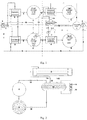
- FIG 1 is a schematic diagram of a distributed energy transforming system according to an embodiment of the invention.
- the distributed energy transforming system according to the embodiment of the invention includes a heat pump I, a pneumatic motor J, a circulating loop through which salt water circulates, and a circulating loop through which fresh water circulates.
- the heat pump I is configured to absorb heat, using its working medium, from the salt water circulating in the circulating loop so that the salt water is cooled, and then compress the working medium with the absorbed heat to further increase the temperature of the working medium, in order for heating the fresh water in the other circulating loop using the working medium.
- the heat pump I includes for example an electrical motor 8 and a compressor connected to the electrical motor 8, as well as working medium pipelines connected to the compressor and the medium within the pipelines.
- the fresh water heated by the working medium of the heat pump is used to heat and vaporize an input pressure working medium of the pneumatic motor J into pressure working medium gas for actuating the pneumatic motor J, and then the fresh water with a decreased temperature because of heating the input pressure working medium is reheated by the working medium of the heat pump I and subsequently used to reheat the input pressure working medium of the pneumatic motor J, so that the fresh water is repeatedly heated and cooled in the other circulating loop.
- the salt water cooled by the working medium of the heat pump is used to condense the output pressure working medium gas of the pneumatic motor J, so that the temperature of the salt water is increased due to the condensation, and then the salt water with the increased temperature is cooled again by the working medium of the heat pump I absorbing heat from the salt water and is used to again condense the output pressure working medium gas of the pneumatic motor J, as a result, the salt water is repeatedly cooled and heated in the corresponding circulating loop.
- the circulating loops are configured to unidirectionally circulate the salt water and the fresh water therein, respectively, so that the salt water is repeatedly cooled and heated during its circulation in the corresponding circulating loop, and the fresh salt water is repeatedly heated and cooled during its circulation in the corresponding circulating loop.
- the circulating loops may be designed as desired using various pipelines, valves, pumping devices, evaporators, condensers, vapor generators, and so on, and fluid storage tanks respectively for storing temporarily the salt water and the fresh water may be arranged in the circulating loops as desired. Accordingly, the present invention does not apply limitation on the implementation of the circulating loops, provided that the salt water and the fresh water can be circulated in the loops and repeatedly cooled and heated.
- a condenser C in the distributed energy transforming system is configured to allow the cooled salt water from a fluid storage tank E to condense the output pressure working medium gas (i.e. ammonia gas) of the pneumatic motor J flowing to a shell pass of the condenser C into pressure working medium liquid (i.e. liquid ammonia) when flowing through a tube pass of the condenser C, and the pressure working medium liquid returns to a vapor generator D as the input pressure working medium (i.e. liquid ammonia) of the pneumatic motor J.
- the output pressure working medium gas i.e. ammonia gas
- pressure working medium liquid i.e. liquid ammonia
- the vapor generator D is configured to, when flowing through a tube pass of the vapor generator D, allow the heated fresh water from the fluid storage tank F to heat and vaporize the input pressure working medium of the pneumatic motor J in the shell pass of the vapor generator D as the pressure working medium gas for actuating the pneumatic motor J.
- the distributed energy transforming system may further include an evaporator A and a condenser B.
- the evaporator A is configured to allow the working medium of the heat pump I to, when flowing through a shell pass of the evaporator A, absorb heat from the salt water from a fluid storage tank G that flows to a tube pass of the evaporator A, so that the working medium of the heat pump I vaporizes.
- the condenser B is configured to allow the compressed working medium of the heat pump I to, when flowing through the shell pass of the condenser B, heat the fresh water from a fluid storage tank H that flows to the tube pass of the condenser B, so that the working medium of the heat pump I condenses and then is returned to the evaporator A.
- the heat pump I is configured to both cool the salt water and heat the fresh water
- the cooled salt water is used for condensing the output pressure working medium gas of the pneumatic motor J to reduce the exhaust pressure of the pneumatic motor J
- the heated fresh water is used to heat and vaporize the input pressure working medium of the pneumatic motor J to increase the pressure of the input pressure working medium of the pneumatic motor J, so that a pressure difference between a working medium inlet and a working medium outlet of the pneumatic motor J, i.e., between the input pressure working medium gas and the output pressure working medium gas of the pneumatic motor J, is significantly increased, so that the output power of the pneumatic motor J is improved and thus more electricity can be generated by the pneumatic motor J.
- the salt water is circulated within one corresponding circulating loop and the fresh water is circulated within the other circulating loop, without discarding energy from the energy transforming system to the outside, thereby avoiding energy loss from the energy transforming system and improving the COP of the energy transforming system.
- energy storage by the salt water is implemented when the salt water absorbs heat from the output pressure working medium gas of the pneumatic motor J and condenses the output pressure working medium gas, the heat stored by the salt water may be absorbed by the heat pump, so that the energy loss from the system is avoided.
- the "waste heat" generated by the heat pump I cooling the salt water is utilized by the heat pump I to heat the fresh water, thus no actual waste heat is generated in the entire system.
- the circulating loop for the salt water may be constituted by the evaporator A, the fluid storage tank E, the condenser C and the fluid storage tank G which are sequentially connected by pipelines, and the fluid storage tank G is also connected to the evaporator A via a pipeline, thereby forming the enclosed circulating loop, and pumping devices such as water pumps 4 which are used to cause the salt water to circulate through the circulating loop may be arranged at desired positions along the pipelines.
- a water pump 4 may be provided along the pipeline between the evaporator A and the fluid storage tank E and used to transfer the cooled salt water from the evaporator A to the fluid storage tank E for storage; a water pump 4 may be provided along the pipeline between the fluid storage tank E and the condenser C and used to transfer the salt water from the fluid storage tank E to the condenser C; and a water pump 4 may be provided along the pipeline between the fluid storage tank G and the evaporator A and used to transfer the salt water from the fluid storage tank G to the evaporator A.
- the invention is not limited thereto, in contrary, the water pumps may be provided along the specific pipelines as actually desired.
- the circulating loop for the fresh water may be constituted by the condenser B, the fluid storage tank F, the vapor generator D and the fluid storage tank H which are sequentially connected by pipelines, and the fluid storage tank H is also connected to the condenser B via a pipeline, thereby forming the enclosed circulating loop, and pumping devices such as water pumps 4 which are used to cause the fresh water to circulate through the circulating loop may be arranged at desired positions along the pipelines.
- a water pump 4 may be provided along the pipeline between the condenser B and the fluid storage tank F and used to transfer the heated fresh water from the condenser B to the fluid storage tank F for storage; a water pump 4 may be provided along the pipeline between the fluid storage tank F and the vapor generator D and used to transfer the fresh water from the fluid storage tank F to the vapor generator D; and a water pump 4 may be provided along the pipeline between the fluid storage tank H and the condenser B and used to transfer the fresh water from the fluid storage tank H to the condenser B.
- the invention is not limited thereto, in contrary, the water pumps may be provided along the specific pipelines as actually desired.
- the salt water is used as the circulating fluid for one of the circulating loops
- the fresh water i.e. ordinary water
- the present invention is not limited thereto, and other fluids (e.g. other types of liquid or even gas) can also be adopted without conflicts, provided that these fluids can maintain their flowable state at the desired operating temperature for the purpose of circulating in the loops and heat exchanging with the working medium of the heat pump and the pressure working medium of the pneumatic motor at the designated temperature.
- the various embodiments of the present invention are described illustratively by taking the salt water and the fresh water as the circulating fluids.
- the salt water is adopted as the first fluid because it can maintain flowable at a temperature below 0°C, and can be obtained widely at a low cost.
- the fresh water refers to ordinary water with a freezing point of 0°C.
- the fluid storage tanks G and E are respectively configured to store salt water of different temperatures in the circulating loop for salt water
- the fluid storage tanks H and F are respectively configured to store fresh water of different temperatures in the other circulating loop for fresh water.
- the fluid storage tank G is configured to store the salt water that is heated by condensing the output pressure working medium gas of the pneumatic motor J, here the salt water is generally heated to a temperature above 0°C, such as between 0°C and 20°C, or between 0°C and 12°C, and preferably a temperature of 12°C, or any other temperature as desired.
- the heat pump I absorbs heat from the salt water from the fluid storage tank G to cool the salt water, and the cooled salt water is stored in the fluid storage tank E, here the salt water is generally cooled to a temperature below 0°C, such as between -20°C and 0°C, or between -12°C and 0°C, and preferably a temperature of -12°C, or any other temperature as desired.
- the fluid storage tank H is configured to store the fresh water that is cooled by heating the input pressure working medium of the pneumatic motor J, here the fresh water generally has a temperature between 20°C and 60°C, such as between 30°Cand 50°C, and between 35°C and 45°C, and preferably a temperature of 40°C, or any other temperature as desired.
- the heat pump I heats the fresh water from the fluid storage tank H, and the heated fresh water is stored in the fluid storage tank F, where the heated fresh water generally has a temperature between 90°C and 60°C, such as between 80°C and 65°C, and preferably a temperature of 75°C, or any other temperature as desired.
- the working medium of the heat pump I is for example carbon dioxide (CO 2 ), and the pressure working medium of the pneumatic motor J is for example ammonia.
- CO 2 carbon dioxide
- the pressure working medium of the pneumatic motor J is for example ammonia.
- other kinds of media may be adopted as the working medium of the heat pump I and the pressure working medium of the pneumatic motor J, provided that these media can vaporize and condense at the predefined temperatures to exchange heat with the external fluid such as salt water or fresh water.
- freon can also be adopted as the pressure working medium of the pneumatic motor J.
- the evaporator A In the case where CO 2 is adopted as the working medium (i.e. refrigerant) of the heat pump I, it is preferable for the evaporator A to cool the salt water to a temperature of about -12°C in order for a high cooling COP of the evaporator A, e.g. a cooling COP of about 2 in this case.
- Other kinds of media may be used in the heat pump I, provided that these media allow the heat pump I to absorb heat from the salt water within the evaporator A and transfer heat to the fresh water within the condenser B.
- the fresh water in the fluid storage tank H preferably has a temperature of 40°C and the fresh water in the fluid storage tank F preferably may have a temperature of 75°C.
- the heat pump I can achieve a COP of about 3 in heating the fresh water.
- liquid ammonia e.g. environment friendly refrigerant of liquid ammonia
- the vapor pressure generated by the vaporization of the liquid ammonia in the vapor generator D is 16.7KG.
- the resulting backpressure of the pneumatic motor J is about 6.7KG, thus a net pressure difference of about 10KG, which is significantly higher than that in the prior art, is obtained for the pneumatic motor J in the inventive system, thereby improving the output power of the pneumatic motor J, and hence improving the electricity generation efficiency if the pneumatic motor J is used for driving a power generator.
- the components such as the fluid storage tanks, evaporators, condensers, vapor generators, pipelines and valves in the systems according to the embodiments of the present invention are preferably thermally insulated, to prevent unexpected heat exchange with the external environment.
- the energy transforming system of the embodiment may further include a working medium liquid storage tank 14, which is positioned at a lower position than the first condenser C, fluidly connected to the first condenser C via a valve 13, and fluidly connected to the vapor generator D via a valve 18.
- a working medium liquid storage tank 14 which is positioned at a lower position than the first condenser C, fluidly connected to the first condenser C via a valve 13, and fluidly connected to the vapor generator D via a valve 18.
- the valve 13 when the valve 13 is open, the valve 18 is closed so that the condenser C is in communication with the working medium liquid storage tank 14 and meanwhile the tank 14 is fluidly disconnected from the vapor generator D, thus the pressure working medium liquid obtained from the condensation in the condenser C can flow into the tank 14 by gravity (or by a pumping device).
- the valve 13 is changed to be closed and the valve 18 is changed to be open, so that the tank 14 is fluidly disconnected from the condenser C but is in communication with the vapor generator D, thus the pressure working medium liquid collected in the tank 14 may return to the vapor generator D and subsequently be vaporized as the input pressure working medium gas of the pneumatic motor J.
- the valve 13 when the liquid level in the tank 14 is lower than a predefined low liquid level threshold 20, the valve 13 is changed to be open and the valve 18 is changed to be closed, so that the tank 14 is fluidly disconnected from the vapor generator D but fluid reconnected with the condenser C, thus the pressure working medium liquid obtained from the condensation in the condenser C can flow into the tank 14.
- the predefined low liquid level threshold 20 is lower than the predefined high liquid level threshold 19.
- the valves 13 and 18 may be electric valves, which are driven to be open or closed as above by a sensor 15 configured for detecting the liquid level in the tank 14 when the sensor 15 detects that the liquid level is higher than the predefined high liquid level threshold 19 or lower than the predefined low liquid level threshold 20.
- the valves 13 and 18 are check valves. When the valve 13 is open, the pressure working medium liquid is allowed to flow in a direction from the condenser C to the working medium liquid storage tank 14; and when the valve 18 is open, the pressure working medium liquid is allowed to flow in a direction from the tank 14 to the vapor generator D.
- the tank 14 may be further fluidly connected to the condenser C via another pipeline different from the pipeline where the valve 13 is located, and a valve 12 and a pneumatic power generator 11 which are serially connected are arranged along the another pipeline to control the pressure working medium gas above the pressure working medium liquid within the tank 14 to flow into the condenser C.
- the tank 14 may be further fluidly connected to the vapor generator D via another pipeline different from the pipeline where the valve 18 is located, and a valve 16 and a gas storage tank 17 which are serially connected are arranged along the another pipeline, where the gas storage tank 17 is connected between the vapor generator D and the valve 16 and configured to separate the pressure working medium gas of the pneumatic motor coming from the vapor generator D from the pressure working medium liquid of the pneumatic motor carried by the pressure working medium gas and to temporarily store the pressure working medium gas as necessary.
- the value 16 is configured to control the pressure working medium gas generated in the vapor generator D to flow to the tank 14.
- the valves 12 and 16 may be electric valves under the control of the detected signal of the sensor 15 for liquid level, and the gas storage tank 17 may be substituted by any other device having a liquid and gas separating function.
- the liquid level sensor 15 detects the liquid level is higher than the predefined high liquid level threshold 19 and generates an electric signal for driving the electric valve 12 to change from an open state to a close state and for driving the electric valve 16 to change from a closed state to an open state, thus the high pressure gas (i.e.
- the pressure working medium gas obtained from the vaporization in the vapor generator D) in the gas storage tank 17 is transferred to the tank 14 via the valve 16 so that the pressure in the tank 14 is increased, resulting in the closing of the check valve 13, and then the check valve 18 is opened due to the gravity of the pressure working medium in the tank 14 so that the tank 14 is in communication with the vapor generator D and the pressure working medium liquid can flow back to the vapor generator D from the tank 14.
- the liquid level sensor 15 detects the liquid level is lower than the predefined low liquid level threshold 20 and generates an electric signal for driving the electric valve 12 to change from the closed state to the open state and driving the electric valve 16 to change from the open state to the closed state, at this time, the pressure inside the tank 14 is higher than that inside the shell pass of the condenser C (through which the pressure working medium gas and liquid of the pneumatic motor J flows) so that the pressure difference therebetween can be used to drive the pneumatic power generator 11 to generate electricity, and the generated electricity preferably flows through the wire 23 to heat the heating tube 22, which in turn assists to heat the fresh water in the fluid storage tank F so that additional heat is stored in the fluid storage tank F.
- the check valve 13 changes from the closed state to the open state under the action of the gravity of the pressure working medium liquid in the condenser C, and at this time, because the pressure inside the shell pass of the vapor generator D (through which the pressure working medium liquid and gas of the pneumatic motor J flows) is higher than that inside the tank 14, so that the check valve 18 changes from the open state to the closed state, and hence the tank 14 is fluidly disconnected from the vapor generator D.
- This approach saves significant electricity compared with the traditional way of returning the working medium using an electric pump, and is high-pressure resistant, leakage proof, and highly efficient.
- the heat pump I includes the electrical motor 8 and the compressor driven by the electrical motor, and at least partial fresh water from the fluid storage tank H is used for water-cooling the electrical motor 8, and the fresh water after the water-cooling returns to the fluid storage tank F; and/or, the pneumatic motor J is connected to and drive a power generator, and at least partial fresh water from the fluid storage tank H is used for water-cooling the power generator, and the fresh water after the water-cooling returns to the fluid storage tank F.
- the heat generated by mechanical movements of the devices in the system can also be stored and utilized, to avoid any waste heat.
- Figure 3 is a schematic diagram of the distributed energy transforming method according to the embodiment of the invention. As shown in Figure 3 , the method may include:
- the circulating loops which are the same as those in the above embodiments, are used to unidirectionally circulate the salt water and the fresh water therein.
- the working medium of the heat pump I may absorb heat from and thus cool the salt water from the fluid storage tank G, and the cooled salt water is transferred to the fluid storage tank E.
- the heat pump I may further compress its working medium carrying the absorbed heat to further increase the temperature of its working medium, so that the fresh water from the fluid storage tank H can be heated by the working medium of the heat pump I, and the heated fresh water is transferred to the fluid storage tank F.
- the heated fresh water from the fluid storage tank F may be transferred to heat and vaporize the input pressure working medium of the pneumatic motor J as the pressure working medium gas for actuating the pneumatic motor J, and the fresh water after heating the input pressure working medium is returned to the fluid storage tank H.
- the cooled salt water from the fluid storage tank E is transferred to condense the output pressure working medium gas of the pneumatic motor J and then returned to the fluid storage tank G.
- the cooling and heating in the energy transforming method of the embodiment of the present invention can be implemented by the condenser and the evaporator.
- the cooled first fluid from the fluid storage tank E flows through the tube pass of the condenser C to condense the output pressure working medium gas (e.g. ammonia gas) of the pneumatic motor J that flows into the shell pass of the condenser C, thereby obtaining the pressure working medium liquid (i.e. liquid ammonia) which is then returned to the vapor generator D as the input pressure working medium (i.e. liquid ammonia) of the pneumatic motor J.
- the output pressure working medium gas e.g. ammonia gas
- the pressure working medium liquid i.e. liquid ammonia
- the heated fresh water from the fluid storage tank F is used to heat and vaporize the input pressure working medium of the pneumatic motor J in the shell pass of the vapor generator D as the pressure working medium gas for actuating the pneumatic motor J, when flowing through the tube pass of the vapor generator D.
- the working medium of the heat pump I may flow through the shell pass of the evaporator A and absorb heat from the salt water flowing into the tube pass of the evaporator A from the fluid storage tank G, so that the working medium of the heat pump I vaporizes and the salt water is cooled.
- the compressed working medium of the heat pump I may flow into the shell pass of the condenser B to heat the fresh water flowing into the tube pass of the condenser B from the fluid storage tank H, so that the working medium of the heat pump I condenses and then transferred back to the evaporator A.
- the shell pass and the tube pass are exchangeable in the disclosure as desired without conflicts.
- the circulating loop for the salt water and that for the fresh water may have the same structure as those in the previous embodiments.
- salt water is adopted as the circulating fluid in one of the circulating loops
- ordinary fresh water is adopted as the circulating fluid in the other circulating loop
- the circulating fluid in the disclosure is not limited to the salt water or fresh water, and any other fluids such as other kind of liquid or even gas, as long as they can maintain at the flowable state at the desired operating temperature for the purpose of circulating in the loops and exchanging heat with the working medium of the heat pump and the pressure working medium of the pneumatic motor at the designated temperature, can also be adopted, without conflicts.
- the various embodiments of the present invention are described illustratively by taking the salt water and the fresh water as the circulating fluids.
- the salt water is adopted as the first fluid because it can maintain flowable at a temperature below 0°C and can be obtained widely at a low cost.
- the fresh water refers to ordinary water with a freezing point of 0°C.
- the fluid storage tank G is configured to store the salt water that is heated by condensing the output pressure working medium gas of the pneumatic motor J, here the salt water is generally heated to a temperature above 0°C, such as between 0°C and 20°C, or between 0°C and 12°C, and preferably a temperature of 12°C, or any other temperature as desired.
- the heat pump I absorbs heat from the salt water from the fluid storage tank G to cool the salt water, and the cooled salt water is stored in the fluid storage tank E, here the salt water is generally cooled to a temperature below 0°C, such as between -20°C and 0°C, or between -12°C and 0°C, and preferably a temperature of -12°C, or any other temperature as desired.
- the fluid storage tank H is configured to store the fresh water that is cooled by heating the input pressure working medium of the pneumatic motor J, here the fresh water generally has a temperature between 20°C and 60°C, such as between 30°Cand 50°C, and between 35°C and 45°C, and preferably a temperature of 40°C, or any other temperature as desired.
- the heat pump I heats the fresh water from the fluid storage tank H, and the heated fresh water is stored in the fluid storage tank F, where the heated fresh water generally has a temperature between 90°C and 60°C, such as between 80°C and 65°C, and preferably a temperature of 75°C, or any other temperature as desired.
- the working medium of the heat pump I is for example carbon dioxide (CO 2 ), and the pressure working medium of the pneumatic motor J is for example ammonia.
- CO 2 carbon dioxide
- the pressure working medium of the pneumatic motor J is for example ammonia.
- other kinds of media may be adopted as the working medium of the heat pump I and the pressure working medium of the pneumatic motor J, provided that these media can vaporize and condense at the predefined temperatures to exchange heat with the external fluid such as salt water or fresh water.
- freon can also be adopted as the pressure working medium of the pneumatic motor J.
- the evaporator A In the case where CO 2 is adopted as the working medium (i.e. refrigerant) of the heat pump I, it is preferable for the evaporator A to cool the salt water to a temperature of about -12°C in order for a high cooling COP of the evaporator A, e.g. a cooling COP of about 2 in this case.
- Other kinds of media may be used in the heat pump I, provided that these media allow the heat pump I to absorb heat from the salt water within the evaporator A and transfer heat to the fresh water within the condenser B.
- the fresh water in the fluid storage tank H preferably has a temperature of 40°C and the fresh water in the fluid storage tank F preferably may have a temperature of 75°C.
- the heat pump I can achieve a COP of about 3 in heating the fresh water.
- liquid ammonia e.g. environment friendly refrigerant of liquid ammonia
- the vapor pressure generated by the vaporization of the liquid ammonia in the vapor generator D is 16.7KG.
- the resulting backpressure of the pneumatic motor J is about 6.7KG, thus a net pressure difference of about 10KG, which is significantly higher than that in the prior art, is obtained for the pneumatic motor J in the inventive system, thereby improving the output power of the pneumatic motor J, and hence improving the electricity generation efficiency if the pneumatic motor J is used to drive a power generator and obtaining a COP of about 5 for the power generator.
- the method may further include: fluidly connecting the condenser C to the working medium liquid storage tank 14 while maintaining the tank 14 being fluidly disconnected from the vapor generator D, so that the pressure working medium liquid obtained from the condensing flows into the tank 14, and when the liquid level inside the tank 14 is higher than the predefined high liquid level threshold 19, fluidly disconnecting the tank 14 from the condenser C and fluidly connecting the tank 14 to the vapor generator D, to enable the pressure working medium liquid in the tank 14 to return to the vapor generator D.
- the tank 14 when the liquid level inside the tank 14 is lower than the predefined low liquid level threshold 20, the tank 14 is fluidly disconnected from the vapor generator D but is fluidly reconnected to the condenser C to allow the pressure working medium liquid obtained from the condensing to flow into the tank 14.
- the predefined low liquid level threshold 20 is below the predefined high liquid level threshold.
- a pressure difference between the inside of the tank 14 and the inside of the shell pass of the condenser C may drive the pneumatic power generator 11 for electricity generation, and the generated electricity is preferably used to assist in heating the fresh water in the fluid storage tank F.
- the energy transforming method according to the embodiment of the invention may further include water-cooling the motor 8 by at least a part of the fresh water from the fluid storage tank H and transferring the part of fresh water after the water-cooling to the fluid storage tank F, and water-cooling the power generator by at least another part of the fresh water from the fluid storage tank H and transferring the another part of fresh water after the water-cooling to the fluid storage tank F.
- water-cooling the motor 8 by at least a part of the fresh water from the fluid storage tank H and transferring the part of fresh water after the water-cooling to the fluid storage tank F
- water-cooling the power generator by at least another part of the fresh water from the fluid storage tank H and transferring the another part of fresh water after the water-cooling to the fluid storage tank F.
- the fluid storage tanks G, E, H and F, the working medium liquid storage tank 14, the evaporator A, the vapor generator D, the condenser C and/or the condenser D may be thermally insulated.
- the circulating loops, the fluids such as salt water and fresh water, the working medium of the heat pump and the pressure working medium of the pneumatic motor are the same as those in the energy transforming system, and thus description thereof is omitted herein.
- the overall concept of this specific application lies in a nighttime energy storage mode and a daytime electricity generation mode.
- the heat pump stores heat (including sensible heat and latent heat) in the fluid storage tanks E and F using ice water and hot water as carrier media until the time for valley electricity ends.
- the daytime electricity generation mode the cold and heat energy stored in the fluid storage tanks E and F is comprehensively utilized for electricity generation.
- the nighttime energy storage mode and the daytime electricity generation mode alternate repeatedly.
- waste heat is regarded as very common and not utilized sometimes.
- indoor cooling is required in summer, meanwhile a lot of heat is dissipated by the outdoor units of the air conditioner as dispensable waste heat.
- waste heat is stored in the large fluid storage tank F using water as the carrier medium and is then in the daytime used to heat the pressure working medium (e.g. liquid ammonia or freon) of the vapor generator D to generate high-pressure vapor for driving the pneumatic motor, so that the waste heat is utilized and the COP of heating is as high as 3.
- the pressure working medium e.g. liquid ammonia or freon
- waste cold energy is stored in the large fluid storage tank E using salt water as the carrier medium and is then in the daytime used to condense the exhaust vapor of the pneumatic motor J, here the COP of storing the cold energy is 2.
- the present invention is featured by cooperatively utilize both heat and cold, thereby obtaining high COP.
- ammonia or freon gas of the pneumatic motor does expansion work inside the pneumatic motor, the resulting exhaust vapor is transferred to the condenser C, and unlike in the prior art, a lot of the dissipated heat of condensation is absorbed and stored by the ice water from the fluid storage tank E without waste, and is absorbed in the evaporator A and reused in the nighttime. Accordingly, the heat of condensation of the working medium of the pneumatic motor is stored and reused in the present invention. Further, the exhaust pressure of the pneumatic motor is significantly reduced by the ice water from the liquid storage tank E, so that the pressure difference between the working medium inlet and the working medium outlet of the pneumatic motor is increased, thereby improving the power of the pneumatic motor and hence the generated electricity.
- the working medium i.e. refrigerant
- the working medium i.e. refrigerant
- the working medium i.e. refrigerant
- the working medium i.e. refrigerant
- the working medium i.e. refrigerant
- the working medium i.e. refrigerant
- the working medium i.e. refrigerant
- the condenser B condenses into liquid refrigerant while dissipating heat, and returns to the evaporator A via a pipeline 2, so that one cooling cycle is completed.
- the heat of condensation dissipated in the condenser B is transferred to the low-temperature water 3 inside the tube pass of the condenser B, so that the low-temperature water 3 is raised in temperature to 75°C and then stored in the fluid storage tank F for later usage, thereby the nighttime energy storage mode is achieved.
- a water pump 4 starts operating to transfer the high-temperature water from the fluid storage tank F to the vapor generator D, and the high-temperature water heats the liquid ammonia inside the shell pass of the vapor generator D to generate high-pressure ammonia vapor, which enters into the pneumatic motor J via a pipeline 5 to conduct the expansion working, thereby enabling the pneumatic motor to drive a power generator for electricity generation.
- the exhaust vapor generated from the pneumatic motor J flows to the condenser C via a pipeline 6 and condenses while dissipating heat, to meanwhile heat the low-temperature salt water of -12°C from the fluid storage tank E to a temperature between 0°C and 12°C, and the heated salt water is then stored in the fluid storage tank G for usage in the nighttime, at the same time, the exhaust pressure of the pneumatic motor J is decreased, thereby increasing the pressure difference between the working medium inlet and the working medium outlet of the pneumatic motor and improving electricity generation.
- the liquid ammonia in the condenser C is transferred back to the vapor generator D so that one operating cycle is completed, thereby implementing the daytime electricity generation mode.
- the distributed energy transforming system of the invention is applicable to fields such as wind and solar energy storage, valley electricity storage, and thermal power generation, the but present invention is not limited thereto.
- the working medium of the heat pump exchanges heat with the working medium of the pneumatic motor indirectly, i.e. by means of the first circulating loop and the carrier medium therein as well as the second circulating loop and the carrier medium therein.
- the inventor found that such energy storage media might be omitted in some scenarios, that is, the energy storage portions, i.e.
- the first circulating loop and/or the second circulating loop may be omitted from the distributed energy transforming method and system described above in combination with Figures 1 to 3 , thus the working medium of the heat pump exchanges heat with the working medium of the pneumatic motor directly, thus obtaining varied energy transforming method and system which can amplify and output the input energy in real time and will be described in detail below in combination with Figures 4 and 5 , in which similar numerals as Figures 1 and 2 represent parts with similar functions as in Figures 1 and 2 and thus detailed description thereof is omitted below.
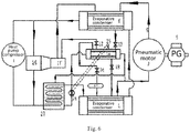
- the energy transforming system may include a heat pump I, a pneumatic motor J, and evaporative condensers K and L, the heat pump I is fluidly connected to both the evaporative condensers K and L via pipelines, and the evaporative condensers K and L are fluidly connected via a pipeline 30, so that the working medium of the heat pump I is allowed to circulate through the evaporative condensers K and L and the pipeline 30.
- the pneumatic motor J is fluidly connected to both the evaporative condensers K and L via pipelines, and the evaporative condensers K and L are further fluidly connected via a pipeline 40, so that the pressure working medium of the pneumatic motor J is allowed to circulate through the evaporative condensers K and L and the pipeline 40.
- the working medium of the heat pump I is used to absorb heat from the output pressure working medium gas of the pneumatic motor J, which thus condenses into pressure working medium liquid that is transferred as the input pressure working medium of the pneumatic motor J.
- the heat pump I is configured to compress its working medium after absorbing the heat to further increase the temperature of the working medium, which is then used for heating and vaporizing the input pressure working medium of the pneumatic motor J within the evaporative condenser L as pressure working medium gas, that actuates the pneumatic motor J and then output by the pneumatic motor J as the output pressure working medium gas of the pneumatic motor J.
- the working medium of the heat pump I that has a decreased temperature because of heating the input pressure working medium of the pneumatic motor J within the evaporative condenser L is transported to the evaporative condenser K to again absorb heat from the output pressure working medium gas of the pneumatic motor J, so that the working medium of the heat pump I repeatedly undergoes the above processes of absorbing heat, raising its temperature and lowering its temperature.
- the working medium of the heat pump I may flow through a tube pass of the evaporative condenser K and vaporize after absorbing heat from the pressure working medium of the pneumatic motor J that flows through a shell pass of the evaporative condenser K, meanwhile the output pressure working medium gas of the pneumatic motor J that flows through the shell pass of the evaporative condenser K condenses after dissipating the heat.
- the compressed working medium of the heat pump I condenses after dissipating heat when flowing through a tube pass of the evaporative condenser L, and the input pressure working medium of the pneumatic motor J vaporizes after absorbing the heat in a shell pass of the evaporative condenser L.
- the energy transforming system in the above varied embodiment may further include a working medium liquid storage tank 14, which is positioned at a lower position than the evaporative condenser K, fluidly connected to the evaporative condenser K via a valve 13, and fluidly connected to the evaporative condenser L via a valve 18.
- the working medium liquid storage tank 14 and the related valves operate in the same manners as in the above embodiments.
- the evaporative condenser K is in communication with the tank 14 which is meanwhile maintained fluidly disconnected from the evaporative condenser L, so that the pressure working medium liquid obtained from condensing in the evaporative condenser K flows into the tank 14 and causes the rising liquid level of the pressure working medium liquid in the tank 14.
- the valve 13 When the liquid level of the pressure working medium liquid in the tank 14 becomes higher than a predefined first threshold, the valve 13 is changed to the closed state and the valve 18 is changed to the open state, so that the tank 14 is fluidly disconnected from the evaporative condenser K and fluidly connected to the evaporative condenser L, to allow the pressure working medium liquid obtained from condensing that is stored in the tank 14 to return to the evaporative condenser L.
- the valve 13 is changed to the open state and the valve 18 is changed to the closed state, so that the tank 14 is fluidly disconnected from the evaporative condenser L and fluidly reconnected to the evaporative condenser K, to allow the pressure working medium liquid obtained from condensing in the evaporative condenser K to flow into the tank 14.
- the predefined second threshold is lower than the defined first threshold.
- the working medium liquid storage tank 14 may be further fluidly connected to the evaporative condenser K via another pipeline different from the pipeline where the valve 13 is located, and a valve 12 and a supplementary pneumatic motor 11' which are serially connected are arranged along the another pipeline.
- the tank 14 may be further fluidly connected to the evaporative condenser L via another pipeline different from the pipeline where the valve 18 is located, and a valve 16 and a gas storage tank 17 which are serially connected are arranged along the another pipeline, where the gas storage tank 17 is connected between the evaporative condenser L and the valve 16 and configured to separate the pressure working medium gas of the pneumatic motor J coming from the evaporative condenser L from the pressure working medium liquid of the pneumatic motor J carried by the pressure working medium gas and to temporarily store the pressure working medium gas as necessary.
- the gas storage tank 17 may be substituted by any other device having a liquid and gas separating function.
- a necessary liquid and gas separating device may be arranged along the pipeline 5 as desired to separate the pressure working medium gas of the pneumatic motor J coming from the evaporative condenser L from the pressure working medium liquid coming from the evaporative condenser L before the pressure working medium gas is transported to the pneumatic motor J.
- a pipeline leading from the gas storage tank 17 may be connected to the inlet for the pressure working medium of the pneumatic motor J, so that the gas storage tank 17 may be shared for the liquid and gas separation without additional liquid and gas separating device.
- the valve 12 When the system operates, if the liquid level in the working medium liquid storage tank 14 becomes higher than the predefined first threshold, the valve 12 is changed from the open state to the closed state and the valve 16 is changed from the closed state to the open state, and if the liquid level in the tank 14 becomes lower than the predefined second threshold, the valve 12 is changed from the closed state to the open state and the valve 16 is changed from the open state to the closed state, so that a pressure difference between the inside of the tank 14 and the inside of the evaporative condenser K may drive the supplementary pneumatic motor 11'.
- the valve 13 When the pressure inside the tank 14 balances with the pressure inside the evaporative condenser K, the valve 13 is changed from the closed state to the open state.
- valves 13 and 18 may be check valves, and the valves 12 and 16 may be electric valves.
- the system in the above varied embodiment may further include a supplementary heat pump 26 driven by the supplementary pneumatic motor 11', the heat pump 26 extracts and compresses at least a part of the working medium of the heat pump I from the evaporative condenser K to raise the temperature of the part of the working medium, and the part of the working medium with the raised temperature joins with the working medium compressed and raised in temperature by the heat pump I and flows to the evaporative condenser L.
- a supplementary heat pump 26 driven by the supplementary pneumatic motor 11', the heat pump 26 extracts and compresses at least a part of the working medium of the heat pump I from the evaporative condenser K to raise the temperature of the part of the working medium, and the part of the working medium with the raised temperature joins with the working medium compressed and raised in temperature by the heat pump I and flows to the evaporative condenser L.
- the energy output from the supplementary pneumatic motor 11' can be fully utilized; in addition, by extracting some working medium of the heat pump I from the evaporative condenser K by the supplementary heat pump 26, the temperature of the output pressure working medium gas of the pneumatic motor J that flows to the evaporative condenser K is further decreased, and the extracted working medium is compressed and hence raised in temperature by the supplementary heat pump 26, so that the heat transferred to the evaporative condenser L is further increased, that is, with the use of the supplementary heat pump 26 and the evaporative condensers K and L, the pressure difference between the inlet and the outlet for the pressure working medium gas of the pneumatic motor J is further increased, thereby further improving the power of the pneumatic motor J.
- the system may further include a liquid tank 27, as shown in Figure 6 which shows a schematic diagram of an energy transforming system according to still another varied embodiment of the invention.
- the working medium liquid storage tank 14 is a shell-and-tube liquid storage tank capable of exchanging heat between two working media, and the pressure working medium liquid and gas of the pneumatic motor J may flow through a shell pass of the shell-and-tube liquid storage tank.
- the working medium output from the supplementary heat pump 26 and/or the heat pump I heats the liquid (such as water) in the liquid tank 27, and the heated liquid from the liquid tank 27 is transported to a tube pass of the shell-and-tube liquid storage tank to heat the pressure working medium liquid in the shell pass of the shell-and-tube liquid storage tank before the pressure working medium liquid is transported to the evaporative condenser L.
- the temperature of the pressure working medium liquid in the working medium liquid storage tank 14 differs from the temperature of the pressure working medium liquid and/or gas in the evaporative condenser L, transporting of the pressure working medium liquid from the tank 14 into the evaporative condenser L would affect the pressure stability of the pressure working medium gas transported from the evaporative condenser L to the pneumatic motor J, and hence the stability of the output power of the pneumatic motor J would be affected.
- the inventor thought of the above approach to preheat the pressure working medium liquid in the tank 14, so that the influence of the pressure working medium liquid flowing into the evaporative condenser L on the temperature of the pressure working medium in the evaporative condenser L is reduced or eliminated, and thence the pressure of the input pressure working medium gas of the pneumatic motor J is more stable.
- the liquid level of the pressure working medium of the pneumatic motor inside the working medium liquid storage tank 14 (which is a shell-and-tube liquid storage tank or any other device capable of heat exchanging between different media in this example) is higher than the predefined high liquid level threshold 19, before the tank 14 becomes fluidly connected to the evaporative condenser L, a pump 24 fluidly connected to the liquid tank 27 is triggered to transport the heated liquid from the liquid tank 27 to the tube pass of the tank 14 in order to heat the pressure working medium liquid (e.g. CO 2 liquid of 0°C) of the pneumatic motor in the shell pass of the tank 14, e.g.
- the pressure working medium liquid e.g. CO 2 liquid of 0°C
- the pump 24 is stopped and the pressure working medium liquid in the tank 14 is allowed to flow into the evaporative condenser L, thus the valves 16 and 18 are opened and the valves 12 and 13 are closed so that the tank 14 is fluidly disconnected from the evaporative condenser K but is fluidly connected to the evaporative condenser L, the heated pressure working medium liquid (i.e. the CO 2 liquid) from the tank 14 automatically flows into the evaporative condenser L due to gravity.
- the predefined temperature or pressure as detected by a temperature or pressure sensor 25
- the vapor pressure output by the evaporative condenser L is beneficially maintained stable without little fluctuation, thus the rotation speed of the pneumatic motor and hence the output voltage and current of the power generator driven by the pneumatic motor is stable.
- the valves 16 and 18 are closed, at this time, the pressure in the tank 14 is the same as that in the evaporative condenser L and is significantly higher than the pressure in the evaporative condenser K.
- the pressure working medium gas e.g.
- an energy transforming method is further provided, as shown in Figure 5 , and the method lies in below.
- the working medium of the heat pump I absorbs heat from and hence condenses the output pressure working medium gas of the pneumatic motor J into pressure working medium liquid, which is transported as the input pressure working medium of the pneumatic motor J.
- absorbing the heat from the output pressure working medium gas of the pneumatic motor J by the working medium of the heat pump I may be implemented by direct heat exchanging between these two working media in a heat exchanger, or in an indirect manner in which the working medium of the heat pump I absorbs heat from another medium through a heat exchanger and the another medium absorbs heat from the output pressure working medium gas of the pneumatic motor J through another heat exchanger, but the invention is not limited thereto.
- the working medium with the absorbed heat is compressed by the heat pump I and thus raised in temperature, and is then used to heat and vaporize the input pressure working medium of the pneumatic motor J as pressure working medium gas, which actuates the pneumatic motor J and is output by the pneumatic motor J as the output pressure working medium gas of the pneumatic motor J.
- heating of the input pressure working medium of the pneumatic motor J by the working medium with raised temperature of the heat pump I may be implemented by direct heat exchanging between these two working media in a heat exchanger, or in an indirect manner in which the working medium with raised temperature of the heat pump I heats another medium through a heat exchanger and the another medium heats the input pressure working medium of the pneumatic motor J through another heat exchanger, but the invention is not limited thereto.
- the working medium of the heat pump I that has been cooled by heating the input pressure working medium, is transported to again absorb heat from the output pressure working medium gas of the pneumatic motor J, so that the working medium of the heat pump I repeatedly conducts the processes of absorbing heat and raising and lowering its temperature.
- the working medium of the heat pump I repeatedly conducts the processes of absorbing heat, and raising and lowering its temperature
- the pressure working medium of the pneumatic motor J repeatedly conducts the processes of dissipating heat and condensing, absorbing heat and vaporizing, and lowering its temperature by working.
- absorbing heat from and condensing the output pressure working medium gas of the pneumatic motor J by the working medium of the heat pump I may be implemented in the evaporative condenser K.
- the working medium of the heat pump I absorbs heat and vaporizes when flowing through the tube pass of the evaporative condenser K, while the output pressure working medium gas of the pneumatic motor J may dissipate heat and condense when flowing through the shell tube of the evaporative condenser K.
- heating of the input pressure working medium of the pneumatic motor J by the working medium with raised temperature of the heat pump I may be conducted in the evaporative condenser L, where the compressed working medium of the heat pump I dissipates heat and condenses when flowing through the tube pass of the evaporative condenser L, while the input pressure working medium of the pneumatic motor J absorbs heat and vaporizes in the shell pass of the evaporative condenser L.
- the media flowing through the tube pass and the shell pass of the evaporative condenser K may be exchanged, as long as the above heat exchange can be conducted between the media, and the invention is not limited thereto.
- the energy transforming method may further include:
- the energy transforming method may further include: when the working medium liquid storage tank 14 becomes fluidly connected to the evaporative condenser K again, a pressure difference between the inside of the working medium liquid storage tank 14 and the inside of the evaporative condenser K is used to drive the supplementary pneumatic motor 11'.
- the pneumatic motor J is connected to and drives a power generator, at least a part of the working medium with lowered temperature of the heat pump I that is output from the evaporative condenser L is used to cool the power generator connected with the pneumatic motor J, and subsequently the part of the working medium is transported back to the evaporative condenser K, so that the heat generated by the movement of the power generator is recycled.
- the supplementary heat pump 26 driven by the supplementary pneumatic motor 11' is further included to extract from the evaporative condenser K at least a part of the working medium of the heat pump I and compress the same to raise temperature thereof, then the part of the working medium with the raised temperature joins with the working medium compressed and raised in temperature by the heat pump I and flows to the evaporative condenser L.
- a liquid tank 27 may be further included in the method, as shown in Figure 6 .
- the working medium liquid storage tank 14 is a shell-and-tube liquid storage tank capable of exchanging heat between two working media, and the pressure working medium liquid and gas of the pneumatic motor J may flow through a shell pass of the shell-and-tube liquid storage tank.
- the working medium output from the supplementary heat pump 26 and/or the heat pump I heats the liquid in the liquid tank 27, and the heated liquid from the liquid tank 27 is transported to a tube pass of the shell-and-tube liquid storage tank to heat the pressure working medium liquid in the shell pass of the shell-and-tube liquid storage tank before the pressure working medium liquid is transported to the evaporative condenser L.
- a pump 24 fluidly connected to the liquid tank 27 is triggered to transport the heated liquid from the liquid tank 27 to the tube pass of the tank 14 in order to heat the pressure working medium liquid (e.g. CO 2 liquid of 0°C) of the pneumatic motor in the shell pass of the tank 14, e.g. to a temperature of 30°C and a pressure of 72 kg/cm 2 .
- the pressure working medium liquid e.g. CO 2 liquid of 0°C
- the pump 24 is stopped and the pressure working medium liquid in the tank 14 is allowed to flow into the evaporative condenser L, thus the valves 16 and 18 are opened and the valves 12 and 13 are closed so that the tank 14 is fluidly disconnected from the evaporative condenser K but is fluidly connected to the evaporative condenser L, the heated pressure working medium liquid (i.e. CO 2 liquid) from the tank 14 automatically flows into the evaporative condenser L due to gravity.
- the predefined temperature or pressure as detected by a temperature or pressure sensor 25
- the vapor pressure output by the evaporative condenser L is beneficially maintained stable without little fluctuation, thus the rotation speed of the pneumatic motor and hence the output voltage and current of the power generator driven by the pneumatic motor is stable.
- the valves 16 and 18 are closed, at this time, the pressure in the tank 14 is the same as that in the evaporative condenser L and is significantly higher than the pressure in the evaporative condenser K.
- the pressure working medium gas e.g.
- the evaporative condensers K and L and/or the working medium liquid storage tank 14 may be thermally insulated.
- ammonia NH 3 may be adopted as the working medium of the heat pump I
- carbon dioxide CO 2 may be adopted as the pressure working medium of the pneumatic motor J.
- the temperature and pressure of ammonia at the working medium inlet of the heat pump I are 0°C and 3.38kg/cm 2 , respectively, and/or the temperature and pressure of ammonia at the working medium outlet of the heat pump I are 40°C and 14.8kg/cm 2 , respectively, and/or the temperature and pressure of CO 2 at the pressure working medium inlet of the pneumatic motor J are 40°C and 96kg/cm 2 , respectively, and/or the temperature and pressure of CO 2 at the pressure working medium outlet of the pneumatic motor J are 0°C and 35kg/cm 2 , respectively.
- the temperature and pressure of the working media at various positions may be adjusted according to various parameters of parts in the system, such as the COP of the heat pump I (including COPs of cooling and heating), the working medium of the heat pump I, the COP of the pneumatic motor J, the pressure working medium of the pneumatic motor J, and heat exchange efficiency of the evaporative condenser, so that the energy transforming system can operate generally stably and in balance.
- the COP of the heat pump I can reach 5.76, for example, with its heating COP being 3.36 and its cooling COP being 2.4.
- the liquid ammonia is drawn from the tube pass of the evaporative condenser K and vaporizes, thereby achieving a cooling COP of 2.4, meanwhile the generated cold energy condenses the CO 2 gas in the shell pass of the evaporative condenser K, and the heat dissipated in the condensing of the CO 2 is absorbed by the ammonia, so that the overall temperature of the evaporative condenser K is maintained in a stable range, and the balanced absorbing of heat (NH 3 ) and balanced dissipating of heat (CO 2 ) lasts.
- the ammonia gas is compressed by the compressor and then flows into the tube pass of the evaporative condenser L and dissipates heat, thereby achieving COP of heating of 3.36, meanwhile the dissipated heat is used to heat the CO 2 liquid in the shell pass of the evaporative condenser L, so that the liquidation of ammonia is conducted simultaneously with the vaporization and expansion of CO 2 , and the obtained high-pressure CO 2 gas enters into the pneumatic motor J and expands for working, thereby driving the power generator connected to the pneumatic motor J for electricity generation.
- the overall efficiency of power generation of the pneumatic motor is 35%
- the energy transforming system and method are advantageous as follows.
- modules of devices in an embodiment may be adaptively modified and arranged in one or more devices of the embodiment.
- Several modules in the embodiment may be combined into one module or unit or component, or a module may be divided into multiple modules or units or components. All features and hence any method or process or unit of a device disclosed in the specification may be combined in any manner, unless at least some of the features and/or processes or modules are conflicting.
- each feature disclosed in the specification including the appending claims, abstract and drawings) may be replaced by a substitute feature with the same, equivalent or similar purpose.
Landscapes
- Engineering & Computer Science (AREA)
- Mechanical Engineering (AREA)
- General Engineering & Computer Science (AREA)
- Chemical & Material Sciences (AREA)
- Combustion & Propulsion (AREA)
- Physics & Mathematics (AREA)
- Thermal Sciences (AREA)
- Engine Equipment That Uses Special Cycles (AREA)
Applications Claiming Priority (2)
| Application Number | Priority Date | Filing Date | Title |
|---|---|---|---|
| CN201910112603.3A CN109798159B (zh) | 2019-02-13 | 2019-02-13 | 分布式换能方法和系统 |
| PCT/CN2019/112923 WO2020164255A1 (zh) | 2019-02-13 | 2019-10-24 | 换能方法和系统 |
Publications (2)
| Publication Number | Publication Date |
|---|---|
| EP3926257A1 true EP3926257A1 (de) | 2021-12-22 |
| EP3926257A4 EP3926257A4 (de) | 2023-02-15 |
Family
ID=66562151
Family Applications (1)
| Application Number | Title | Priority Date | Filing Date |
|---|---|---|---|
| EP19914852.9A Withdrawn EP3926257A4 (de) | 2019-02-13 | 2019-10-24 | Umwandlungsverfahren und -system |
Country Status (7)
| Country | Link |
|---|---|
| US (1) | US20220341635A1 (de) |
| EP (1) | EP3926257A4 (de) |
| JP (1) | JP2022520595A (de) |
| KR (1) | KR20210126100A (de) |
| CN (2) | CN109798159B (de) |
| CA (1) | CA3133850A1 (de) |
| WO (1) | WO2020164255A1 (de) |
Families Citing this family (10)
| Publication number | Priority date | Publication date | Assignee | Title |
|---|---|---|---|---|
| CN109798159B (zh) * | 2019-02-13 | 2019-10-25 | 孙诚刚 | 分布式换能方法和系统 |
| DE102019122810A1 (de) * | 2019-08-26 | 2021-03-04 | Eberspächer Climate Control Systems GmbH | Fahrzeugtemperiersystem |
| WO2021248289A1 (zh) * | 2020-06-08 | 2021-12-16 | 孙诚刚 | 换能方法和系统 |
| CN113417709B (zh) * | 2021-06-02 | 2022-04-22 | 中国科学院理化技术研究所 | 耦合高温热泵循环的液态空气储能方法及系统 |
| CN113959122B (zh) * | 2021-09-16 | 2023-03-31 | 青岛海尔空调电子有限公司 | 制冷系统、用于制冷系统的控制方法、控制装置 |
| CN116335785B (zh) * | 2021-12-16 | 2025-08-08 | 中国科学院广州能源研究所 | 一种海岛地热电淡冰联供系统 |
| CN115597306A (zh) * | 2022-11-09 | 2023-01-13 | 双良节能系统股份有限公司(Cn) | 一种低沸点工质回收及储补装置 |
| CN116608451B (zh) * | 2023-06-05 | 2025-01-28 | 深圳爱图仕创新科技股份有限公司 | 循环冷却系统及照明设备 |
| CN116839244B (zh) * | 2023-09-01 | 2023-12-19 | 国网江苏省电力有限公司南京供电分公司 | 多热源热泵相变蓄能型冷热联供系统控制方法与装置 |
| CN119268167B (zh) * | 2024-09-24 | 2025-11-25 | 中国科学院理化技术研究所 | 大温差热泵相变储能系统及储能方法 |
Family Cites Families (26)
| Publication number | Priority date | Publication date | Assignee | Title |
|---|---|---|---|---|
| MX144884A (es) * | 1976-07-30 | 1981-12-01 | Deere & Co | Mejoras a impulsor de turbocargador de ciclo rankine para motores de combustion interna |
| US4251996A (en) * | 1979-06-01 | 1981-02-24 | Carrier Corporation | Heat reclaiming method and apparatus |
| CN86207494U (zh) * | 1986-10-25 | 1988-03-16 | 北京航空学院 | 空气膨胀涡轮连续制冷装置 |
| JP2611185B2 (ja) * | 1994-09-20 | 1997-05-21 | 佐賀大学長 | エネルギー変換装置 |
| US6827104B2 (en) * | 2001-10-24 | 2004-12-07 | Mcfarland Rory S. | Seal and valve systems and methods for use in expanders and compressors of energy conversion systems |
| US20050076639A1 (en) * | 2003-10-14 | 2005-04-14 | Shirk Mark A. | Cryogenic cogeneration system |
| CN101556096B (zh) * | 2004-09-17 | 2011-11-09 | 学校法人同志社 | 热泵、热泵系统、和兰金循环 |
| WO2008106190A2 (en) * | 2007-02-27 | 2008-09-04 | Shirk Mark A | Integrated electrochemical and thermochemical renewable energy production, storage, distribution and recycling system |
| JP2008292026A (ja) * | 2007-05-23 | 2008-12-04 | Ats Japan Corp | 恒温維持装置。 |
| DE102010010614B4 (de) * | 2010-03-08 | 2012-01-26 | GMK Gesellschaft für Motoren und Kraftanlagen mbH | Verfahren und Vorrichtung zur Energieerzeugung in einer ORC-Anlage |
| SE535782C2 (sv) * | 2011-03-21 | 2012-12-18 | Skellefteaa Kraftaktiebolag | Förfarande och system för återvinning av termisk energi från en ångtork |
| CN102679622A (zh) * | 2012-05-22 | 2012-09-19 | 青岛大学 | 一种模块化变热容自匹配多温系统 |
| CN103574988B (zh) * | 2012-08-01 | 2015-09-02 | 吴春渊 | 冷热多功节能系统 |
| ES2692118T3 (es) * | 2014-05-05 | 2018-11-30 | General Electric Technology Gmbh | Sistema de almacenamiento y de descarga de energía eléctrica |
| CN203856601U (zh) * | 2014-05-28 | 2014-10-01 | 孙诚刚 | 一种动力装置 |
| WO2016000016A1 (en) * | 2014-06-30 | 2016-01-07 | Kerbs Autotech Pty Ltd | An internal combustion engine heat energy recovery system |
| US9816401B2 (en) * | 2015-08-24 | 2017-11-14 | Saudi Arabian Oil Company | Modified Goswami cycle based conversion of gas processing plant waste heat into power and cooling |
| CN105571029A (zh) * | 2016-01-27 | 2016-05-11 | 王昊 | 一种实现空调跨季度同步蓄冷蓄热的方法及设备 |
| US9702597B1 (en) * | 2016-02-18 | 2017-07-11 | King Fahd University Of Petroleum And Minerals | System and method for preventing absorbent crystallization in a continuously operating solar-powered absorption cooling system with hybrid storage |
| CN106288513A (zh) * | 2016-09-30 | 2017-01-04 | 广州高菱能源技术有限公司 | 一种带相变蓄冷和蓄热的冷热两用热泵系统 |
| CN107525302B (zh) * | 2017-10-18 | 2018-05-22 | 王金宝 | 一种利用低温热能转换动力并制冷制热发电的装置及方法 |
| TWI672433B (zh) * | 2017-12-29 | 2019-09-21 | 明基能源技術股份有限公司 | 熱能回收系統 |
| CN208458304U (zh) * | 2018-03-22 | 2019-02-01 | 烟台大学 | 一种间接换热的热泵装置 |
| CN109798159B (zh) * | 2019-02-13 | 2019-10-25 | 孙诚刚 | 分布式换能方法和系统 |
| CN110118437B (zh) * | 2019-05-05 | 2021-04-09 | 青岛海田设计事务所有限公司 | 一种用于海洋馆的废热回收利用系统及其工作方法 |
| CN111780074A (zh) * | 2020-06-09 | 2020-10-16 | 孙诚刚 | 外燃机系统和交通工具 |
-
2019
- 2019-02-13 CN CN201910112603.3A patent/CN109798159B/zh active Active
- 2019-10-24 EP EP19914852.9A patent/EP3926257A4/de not_active Withdrawn
- 2019-10-24 KR KR1020217029416A patent/KR20210126100A/ko not_active Ceased
- 2019-10-24 CN CN201980091821.1A patent/CN113474599A/zh active Pending
- 2019-10-24 JP JP2021547318A patent/JP2022520595A/ja not_active Withdrawn
- 2019-10-24 US US17/430,526 patent/US20220341635A1/en not_active Abandoned
- 2019-10-24 CA CA3133850A patent/CA3133850A1/en not_active Abandoned
- 2019-10-24 WO PCT/CN2019/112923 patent/WO2020164255A1/zh not_active Ceased
Also Published As
| Publication number | Publication date |
|---|---|
| JP2022520595A (ja) | 2022-03-31 |
| US20220341635A1 (en) | 2022-10-27 |
| WO2020164255A1 (zh) | 2020-08-20 |
| KR20210126100A (ko) | 2021-10-19 |
| CA3133850A1 (en) | 2020-08-20 |
| EP3926257A4 (de) | 2023-02-15 |
| CN109798159B (zh) | 2019-10-25 |
| CN113474599A (zh) | 2021-10-01 |
| CN109798159A (zh) | 2019-05-24 |
Similar Documents
| Publication | Publication Date | Title |
|---|---|---|
| US20220341635A1 (en) | Transducing method and system | |
| WO2022166392A1 (zh) | 基于二氧化碳气液相变的多级压缩储能装置及方法 | |
| WO2021248289A1 (zh) | 换能方法和系统 | |
| CN103003531A (zh) | 用于储存热电能的热电能量储存系统和方法 | |
| CN102472537B (zh) | 空气调节热水供给系统 | |
| CN202182589U (zh) | 余热、废热回收利用能量平衡系统 | |
| KR101896382B1 (ko) | 3단계 응축열 열교환을 통한 에너지 절감형 냉동 및 제상 시스템 | |
| KR100963221B1 (ko) | 지열원을 이용한 히트펌프시스템 | |
| CN105890221A (zh) | 电能存储和放能系统 | |
| CN102230686A (zh) | 溴化锂吸收-压缩式串联升压制冷/热泵系统 | |
| CN104364587A (zh) | 太阳能系统 | |
| CN107178934A (zh) | 一种空压机余热深度回收利用系统 | |
| US20170198950A1 (en) | Cold Production Apparatus, Including Means for Condensation by Air and Water Simultaneously, and the Method for Implementing Said Facility | |
| US9671175B2 (en) | System for reversibly storing electrical energy as thermal energy | |
| KR200409887Y1 (ko) | 고효율 히트펌프를 이용한 온수 발생장치 | |
| WO2011041767A1 (en) | Heat pump water heater having a sub-cooling arrangement | |
| KR20100027353A (ko) | 냉장냉동장치 | |
| KR20140067513A (ko) | 별도의 제상사이클이 필요없는 히트펌프 시스템 | |
| CN108387021A (zh) | 一种分级热泵蒸汽发生装置 | |
| CN103278000A (zh) | 基于热管与热泵的干燥系统及其使用方法 | |
| KR20140089271A (ko) | 공기 지열 복합 열원 이원 사이클 히트펌프 냉난방 장치 | |
| KR101272021B1 (ko) | 이원 사이클 히트펌프 냉난방 장치 | |
| KR101241816B1 (ko) | 발전기가 구비된 수열교환방식 냉난방장치 | |
| CN103017410B (zh) | 一种冷暖式热管热泵复合循环系统 | |
| KR20140089279A (ko) | 공기 태양열 복합 열원 이원 사이클 히트펌프 냉난방 장치 |
Legal Events
| Date | Code | Title | Description |
|---|---|---|---|
| STAA | Information on the status of an ep patent application or granted ep patent |
Free format text: STATUS: THE INTERNATIONAL PUBLICATION HAS BEEN MADE |
|
| PUAI | Public reference made under article 153(3) epc to a published international application that has entered the european phase |
Free format text: ORIGINAL CODE: 0009012 |
|
| STAA | Information on the status of an ep patent application or granted ep patent |
Free format text: STATUS: REQUEST FOR EXAMINATION WAS MADE |
|
| 17P | Request for examination filed |
Effective date: 20210908 |
|
| AK | Designated contracting states |
Kind code of ref document: A1 Designated state(s): AL AT BE BG CH CY CZ DE DK EE ES FI FR GB GR HR HU IE IS IT LI LT LU LV MC MK MT NL NO PL PT RO RS SE SI SK SM TR |
|
| DAV | Request for validation of the european patent (deleted) | ||
| DAX | Request for extension of the european patent (deleted) | ||
| A4 | Supplementary search report drawn up and despatched |
Effective date: 20230116 |
|
| RIC1 | Information provided on ipc code assigned before grant |
Ipc: F25B 41/20 20210101ALI20230110BHEP Ipc: F25B 30/02 19900101ALI20230110BHEP Ipc: F25B 27/02 19680901ALI20230110BHEP Ipc: F01K 3/08 19680901ALI20230110BHEP Ipc: F01K 17/02 19680901ALI20230110BHEP Ipc: F24H 4/00 19900101ALI20230110BHEP Ipc: F01K 25/10 19680901ALI20230110BHEP Ipc: F25B 29/00 19680901AFI20230110BHEP |
|
| STAA | Information on the status of an ep patent application or granted ep patent |
Free format text: STATUS: THE APPLICATION IS DEEMED TO BE WITHDRAWN |
|
| 18D | Application deemed to be withdrawn |
Effective date: 20230815 |