EP3926341A1 - Procédé et agencement pour la détection de fissures au bord d'un matériau métallique - Google Patents
Procédé et agencement pour la détection de fissures au bord d'un matériau métallique Download PDFInfo
- Publication number
- EP3926341A1 EP3926341A1 EP20180392.1A EP20180392A EP3926341A1 EP 3926341 A1 EP3926341 A1 EP 3926341A1 EP 20180392 A EP20180392 A EP 20180392A EP 3926341 A1 EP3926341 A1 EP 3926341A1
- Authority
- EP
- European Patent Office
- Prior art keywords
- edge
- signal
- metallic material
- time
- crack
- Prior art date
- Legal status (The legal status is an assumption and is not a legal conclusion. Google has not performed a legal analysis and makes no representation as to the accuracy of the status listed.)
- Withdrawn
Links
- 239000007769 metal material Substances 0.000 title claims description 145
- 238000000034 method Methods 0.000 title claims description 42
- 238000001514 detection method Methods 0.000 title description 10
- 230000008859 change Effects 0.000 claims description 20
- 238000005259 measurement Methods 0.000 description 28
- 229910000831 Steel Inorganic materials 0.000 description 8
- 239000010959 steel Substances 0.000 description 8
- 238000007689 inspection Methods 0.000 description 7
- 230000035699 permeability Effects 0.000 description 6
- 239000000463 material Substances 0.000 description 5
- 230000003287 optical effect Effects 0.000 description 5
- 230000010354 integration Effects 0.000 description 4
- 239000002184 metal Substances 0.000 description 4
- 238000010586 diagram Methods 0.000 description 3
- 230000001939 inductive effect Effects 0.000 description 3
- 230000008569 process Effects 0.000 description 3
- 239000012925 reference material Substances 0.000 description 3
- 230000008901 benefit Effects 0.000 description 1
- 238000004364 calculation method Methods 0.000 description 1
- 238000005266 casting Methods 0.000 description 1
- 230000001419 dependent effect Effects 0.000 description 1
- 230000000694 effects Effects 0.000 description 1
- 230000005674 electromagnetic induction Effects 0.000 description 1
- 230000006698 induction Effects 0.000 description 1
- 230000001788 irregular Effects 0.000 description 1
- 238000004519 manufacturing process Methods 0.000 description 1
- 238000012986 modification Methods 0.000 description 1
- 230000004048 modification Effects 0.000 description 1
- 230000004044 response Effects 0.000 description 1
- 238000005096 rolling process Methods 0.000 description 1
- 230000036962 time dependent Effects 0.000 description 1
Images

Classifications
-
- G—PHYSICS
- G01—MEASURING; TESTING
- G01N—INVESTIGATING OR ANALYSING MATERIALS BY DETERMINING THEIR CHEMICAL OR PHYSICAL PROPERTIES
- G01N27/00—Investigating or analysing materials by the use of electric, electrochemical, or magnetic means
- G01N27/72—Investigating or analysing materials by the use of electric, electrochemical, or magnetic means by investigating magnetic variables
- G01N27/82—Investigating or analysing materials by the use of electric, electrochemical, or magnetic means by investigating magnetic variables for investigating the presence of flaws
-
- G—PHYSICS
- G01—MEASURING; TESTING
- G01N—INVESTIGATING OR ANALYSING MATERIALS BY DETERMINING THEIR CHEMICAL OR PHYSICAL PROPERTIES
- G01N33/00—Investigating or analysing materials by specific methods not covered by groups G01N1/00 - G01N31/00
- G01N33/20—Metals
- G01N33/204—Structure thereof, e.g. crystal structure
- G01N33/2045—Defects
-
- G—PHYSICS
- G01—MEASURING; TESTING
- G01N—INVESTIGATING OR ANALYSING MATERIALS BY DETERMINING THEIR CHEMICAL OR PHYSICAL PROPERTIES
- G01N27/00—Investigating or analysing materials by the use of electric, electrochemical, or magnetic means
- G01N27/72—Investigating or analysing materials by the use of electric, electrochemical, or magnetic means by investigating magnetic variables
- G01N27/82—Investigating or analysing materials by the use of electric, electrochemical, or magnetic means by investigating magnetic variables for investigating the presence of flaws
- G01N27/90—Investigating or analysing materials by the use of electric, electrochemical, or magnetic means by investigating magnetic variables for investigating the presence of flaws using eddy currents
- G01N27/9013—Arrangements for scanning
- G01N27/9026—Arrangements for scanning by moving the material
-
- G—PHYSICS
- G01—MEASURING; TESTING
- G01N—INVESTIGATING OR ANALYSING MATERIALS BY DETERMINING THEIR CHEMICAL OR PHYSICAL PROPERTIES
- G01N27/00—Investigating or analysing materials by the use of electric, electrochemical, or magnetic means
- G01N27/72—Investigating or analysing materials by the use of electric, electrochemical, or magnetic means by investigating magnetic variables
- G01N27/82—Investigating or analysing materials by the use of electric, electrochemical, or magnetic means by investigating magnetic variables for investigating the presence of flaws
- G01N27/90—Investigating or analysing materials by the use of electric, electrochemical, or magnetic means by investigating magnetic variables for investigating the presence of flaws using eddy currents
- G01N27/9046—Investigating or analysing materials by the use of electric, electrochemical, or magnetic means by investigating magnetic variables for investigating the presence of flaws using eddy currents by analysing electrical signals
Definitions
- the present disclosure generally relates to quality inspection of a metallic material, and in particular to crack detection at an edge of a metallic material utilising electromagnetic induction.
- a known method of contactless crack measurements of a metallic material is to utilise optical means.
- the metallic material may be irradiated by light wherein a crack may be detected by means of an optical sensor such as a camera.
- Drawbacks with optical methods are that it is not possible to detect cracks which are not visible on the surface of the metallic material, and that colour variations in the metallic material may be interpreted as cracks by the optical sensor.
- Optical methods have been proved to be difficult to use in other applications than for inspection of completely clean and smooth metal surfaces.
- a current is induced in the metallic material, e.g. a slab or a metal sheet, by means of a time-varying magnetic field generated by a transmitter coil fed with a likewise time-varying current.
- the induced current encounters a crack in the metallic material, the crack constitutes an obstacle to the induced current.
- the crack alters the induced current at the crack as compared to a metallic material without a crack.
- the altered current provides a change in the magnetic field around the current.
- the change in the magnetic field is measured by a receiver coil, whereby it can be determined that a crack is present in the inspected surface portion of the metallic material.
- An object of the present invention is to overcome at least some of the above problems, and to provide a solution for detection of cracks at the edge of the metallic material which, at least to some extent, is improved compared to prior art solutions.
- a method of determining a crack at an edge of a metallic material, the edge having a curvature with a radius comprising the steps of:
- a crack depth may be determined independently of the position of the edge and the radius of the curvature of the edge, without having other process parameters affecting the determined crack depth value.
- the characteristic relation between the least two combinations of signal values are independent of the position of the edge and the radius of the curvature of the edge. Hence reliable crack depth measurements may be provided at the edge of the metallic material.
- At least small cracks (typically ⁇ 3mm crack depth) which are particularly difficult to differentiate from variations in the radius of the edge are detectable and measurable by applying the above specified method.
- the method may be carried out by feeding the first current with a first magnitude to the transmitter coil during a first time interval, and controlling the current such that it obtains a second magnitude during a second time interval, repeatedly.
- the first, second and third signal values are all measured during the second time interval in which the current is controlled to obtain the second magnitude.
- the detecting of the magnetic field by means of the receiver coil is embodied by detecting magnetic field changes (i.e. induced voltage or dB/dt).
- dB/dt induced voltage
- the "at a first time at which it has been estimated that any disturbances due to control of the current to obtain the second magnitude have ceased” is at least partly related to a voltage peak (dB/dt) caused by the portion of the magnetic field which does not penetrate into the metallic material. In other words, this voltage peak (dB/dt) should have ceased at the first time.
- the first time is additionally determined at which a current induced in the metallic material due to control of the current to obtain the second magnitude has penetrated deeper in the metallic material than a depth corresponding to surface irregularities of the metallic material and crack depths not desired to be measured.
- the method is independent of the surface irregularities.
- the method further comprises the step of providing the transmitter coil at least partly outside of the edge of the metallic material.
- the receiver coil may according to at least one example embodiment be arranged such that its magnetic center is arranged inside of the edge of the metallic material.
- the step comprises providing the transmitter coil at least partly inside of the edge of the metallic material.
- the transmitter coil may be arranged to overlap the edge of the metallic material, facilitating crack determination.
- the ratio of the portion of the transmitter coil arranged outside of the edge to the portion of the transmitter coil arranged inside of the edge is between 0.1-0.4. It should be understood that any overlap of the edge is referring to an overlap in a plane parallel to the surface of the metallic material.
- the third time is a time at which it has been estimated that any influence of a radius change of the curvature of the edge has ceased.
- the characteristic relation of two signal values, wherein at least one is based on the third time will be independent of the radius of the curvature of the edge.
- the method further comprises the steps of:
- the reference position may e.g. be the magnetic axis of the receiver coil.
- Edge position may include both horizontal and vertical distance to the edge relative the reference position, alternatively only the horizontal distance.
- the step of determining a possible presence of a crack and its crack depth comprises comparing the characteristic relations with corresponding reference signals.
- the method further comprises the steps of:
- the change characteristics of the edge, at least the edge position and the radius of the curvature of the edge can be determined and at least the first, second and/or third times can be chosen based on the determined change characteristics.
- the third time can be determined as a time which the influence of a radius change of the curvature of the edge has ceased.
- the measured signal, or measured signals, based on at least steps S10, S20, S30, S40, S50 and S60, or the determining in step S70, can be compared with reference signals corresponding to a metallic material having no crack at the edge.
- the step of determining a possible presence of a crack and its crack depth comprises using the characteristic relations with corresponding signal values of the first, second, third and/or fourth reference signal.
- the first, second and third times are separate points in time.
- the separate points in time are based on elapsed time from the initialization of controlling the current such that it obtains a second magnitude.
- the first, second and third times are respective short time ranges spanning from -30% to +30% of the respective point in time.
- the first, second and third times or time ranges do not overlap, and/or do not share a common starting or ending time.
- the current is essentially constant.
- the estimation of the magnetic field having penetrated deeper than a deepest crack depth desired to be measured in the metallic material is based on when the feeding the current to the transmitter coil starts, a deepest crack depth desired to be measured and the relative permeability and electrical resistivity of the metallic material.
- the first time is estimated based on a time when control of the current to obtain its second magnitude starts and on a relation between the relative permeability and electrical resistivity of the metallic material, and/or based on the time when the current obtains its second magnitude, the deepest crack depth desired to be measured and the relative permeability and electrical resistivity of the metallic material.
- the first time may e.g. be 100 ⁇ s or between 100 ⁇ s and 700 ⁇ s, such as e.g. between 100 ⁇ s and 500 ⁇ s.
- the first, second and/or third signal value is a respective single signal value, a mean signal value or an integration of the signal during said short time ranges over the first, second and third time, respectively.
- said receiver coil is a first receiver coil and the method further comprising the steps of:
- the coil arrangement i.e. the transmitter coil, and the first and second receiver coils
- Such positioning information can be used e.g. in combination with a positioning arrangement configured to horizontally and vertically re-position the coil arrangement, in order to e.g. keep a constant distance between the coil arrangement and the edge, and between the coil arrangement and the surface of the metallic material, respectively.
- an arrangement for determining a crack at an edge of a metallic material, the edge having a curvature with a radius comprising:
- the transmitter coil is, in operation, configured to be arranged at least partly outside of the edge of the metallic material.
- the receiver coil may according to at least one example embodiment be, in operation, configured to be arranged such that its magnetic center is arranged inside of the edge of the metallic material.
- the transmitter coil is, in operation, configured to be arranged at least partly inside of the edge of the metallic material.
- the transmitter coil may, in operation, be configured to be arranged to overlap the edge of the metallic material, facilitating crack determination.
- the ratio of the portion of the transmitter coil configured to be arranged outside of the edge to the portion of the transmitter coil configured to be arranged inside of the edge is between 0.1-0.4.
- the computing arrangement is arranged to determine the third signal value at the third time being a time at which it has been estimated that any influence of a radius change of the curvature of the edge has ceased.
- the computer arrangement is arranged to determine the first time, additionality to the criteria mentioned above, at which a current induced in the metallic material due to control of the current to obtain the second magnitude has penetrated deeper in the metallic material than a depth corresponding to surface irregularities of the metallic material and crack depths not desired to be measured.
- the computing arrangement is arranged do determined the first signal value, the second signal value and the third signal value at the first time, the second time and the third time, respectively, wherein the first, second and third times are separate points in time.
- the separate points in time are based on elapsed time from the initialization of the control unit to control the signal generator such that the current obtains a second magnitude.
- the first, second and third times are respective short time ranges spanning from -30% to +30% of the respective point in time.
- the first, second and third times or time ranges do not overlap, and/or do not share a common starting or ending time.
- said receiver coil is a first receiver coil
- the arrangement further comprises a second receiver coil arranged to detect the magnetic field
- the computing arrangement is further configured to receive a signal created by the magnetic field detected by the second receiver coil, and configured to determine the position of the edge and the distance from a surface of the metallic material, relative the first and second receiver coils, respectively.
- the arrangement comprises a positioning arrangement configured to adjust the position of the transmitter coil, the first receiver coil, and/or the second receiver coil.
- the determined position of the edge and the distance from a surface of the metallic material, relative the first and second receiver coils, respectively, may be used as input to the positioning arrangement.
- the positioning arrangement may e.g. be configured to keep such position and distance constant.
- the distance from the edge to the first receive coils is typically a horizontal distance, i.e. a distance parallel to a horizontal surface, e.g. the surface of the metallic material.
- the distance from a surface of the metallic material, relative the second receiver coils is a vertical distance perpendicular to the horizontal distance.
- the arrangement presented herein is adapted to detect cracks at an edge in a metallic material by determining the crack depth of a crack.
- the arrangement may be used under extreme conditions, for instance in a metal making process such as during casting or a rolling process.
- the arrangement may in particular be used for accurate crack depth measurement of cracks on rough metallic surfaces.
- Any metallic material which has a conductivity which is high enough to allow a current to be induced in the metallic material may be inspected by means of the methods and arrangements presented herein, e.g. steel.
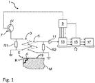
- Fig. 1 shows a schematic view of an example of an arrangement 1 for detecting cracks in a surface 19 at an edge E of a metallic material M.
- the edge E runs along the metallic material M in the longitudinal direction, or direction of movement of the metallic material M, as can be seen in Fig. 2a .
- the edge E has a curvature with a radius R, which may be curved as in Fig. 1 , or edgy.
- Arrangement 1 comprises signal generator 7 arranged to generate an output signal, a control unit 9 arranged to control the output signal of the signal generator 7, a transmitter coil 3 arranged to receive the output signal from the signal generator 7 to thereby generate a magnetic field in a metallic material M which is to be inspected for cracks, a first resistor R1, a receiver coil 5 arranged to detect the magnetic field and to create a signal based on the detected magnetic field, a second resistor R2, an amplifier 11 arranged to amplify the signal from the receiver coil 5, and a computing arrangement 12 arranged to process the signal from the amplifier 11 in order to determine whether a crack C is present in the metallic material M at the edge E by determining a possible crack depth CD.
- the computing arrangement 12 may comprise various subunits such as a first unit 13, a second unit 15, and a third unit 17.
- the present disclosure involves the generation of a magnetic field in the metallic material M at the edge E, detecting the magnetic field, and determining characteristic relations of signals pertaining to the detected magnetic field at certain predetermined times, to thereby be able to determine a crack depth, as will be detailed in the following.
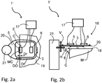
- Figs. 2a and 2b show schematic views of another example of an arrangement 1' for detecting cracks in a surface 19 at and edge E of a metallic material M.
- Fig. 2a is a top view and Fig. 2b is a side view.
- Arrangement 1' of Figs. 2a and 2b is in principle the same as arrangement 1 of Fig. 1 , why mainly the differences between the arrangements are described in the following.
- the signal generator 7, the control unit 9, the amplifier 11 and the computing arrangement 12 are commonly incorporated in component 17 in Figs. 2a and 2b , but will be referred to as visualized in Fig. 1 in the following.
- the arrangement 1' comprises the transmitter coil 3 and a first receiver coil 5 having the same functionality as described with reference to Fig.
- the arrangement 1' comprises a second receiver coil 6 arranged distant to the first receiver coil 5.
- the transmitter coil 3, the first and second receiver coils 5, 6 are here commonly referred to as a coil arrangement 18.
- the arrangement 1' comprises a platform 20 to which the coil arrangement 18 are connected and movable with.
- the platform 20 is coupled to a positioning arrangement 21 configured to adjust the position of the coil arrangement 18, both vertically V and horizontally H, as indicated in Fig. 2b .
- the platform 20 is not needed for being able to re-position the coil arrangement 18, but that each of the transmitter coil 3, the first receiver coil 5 and the second receiver coil 6 may be directly coupled to the positioning arrangement 21.
- Figs. 2a and 2b are omitted in Figs. 2a and 2b for increased comprehensibility, but may be considered to be integrated in the transmitter coil 3 and first receiver coil 5, respectively, or in platform 20.
- the second receiver coil 6 may be assumed to be connected in parallel to a third resistor R3 in the same way as the first receiver coil 5 is connected to the second resistor R2, such third resistor may be integrated into second receiver coil 6 or the platform 20.
- the metallic material M for instance a slab or a metal sheet, which is to be inspected for cracks C, is placed in the vicinity of the transmitter coil 3 and the first and second receiver coils 5, 6. More specifically, the arrangement 1' is arranged such that the transmitter coil 3 arranged at least partly outside of the edge E, indicated by the distance DO, and at least partly inside of the edge E, indicated by the distance DI.
- the ratio of DO/DI is preferably between 0.1 and 0.4.
- the first receiver coil 5 is in Figs. 2a and 2b arranged to partly overlap the edge E, such that its magnetic center MC is arranged inside of the edge E.
- the second receiver coil 6 is in Figs.
- each one of the transmitter coil 3, and first and second receiver coils 5, 6 is a flat coil with a minor propagation along its magnetic axis compared to perpendicularly to its magnetic axis.
- the metallic material M typically move in relation to the coil arrangement 18 during crack inspection to thereby enable inspection along the surface 19 of the metallic material M. and specifically at the edge E of the metallic material M.
- the transmitter coil 3 may be arranged at least partly outside of the edge E.
- the transmitter coil 3 is provided at least partly outside of the edge E of the metallic material M.
- the transmitter coil 3 may additionally be provided at least partly inside of the edge E of the metallic material M.
- the control unit 9 (only shown in Fig. 1 , incorporated into component 17 of Figs. 2a and 2b ) is arranged to provide a control signal to the signal generator 7 (only shown in Fig. 1 , incorporated into component 17 of Figs. 2a and 2b ) to thereby control the output signal, e.g. a current, of the signal generator 7 provided to the transmitter coil 3.
- the signal generator 7 may for instance comprise a transistor which may be controlled by the control unit 9 to be in an open state and thereby provide a current to the transmitter coil 3 or a closed state in which it does not provide a current to the transmitter coil 3.
- control unit 9 is arranged to control the signal generator 7 such that the signal generator generates a current which is essentially constant having a first magnitude I1 in a first time span tOO-tO, as shown in Fig. 3a .
- a first step S10 the current with the first magnitude I1 is fed to the transmitter coil 3.
- a magnetic field is thereby created in the metallic material M at the edge E.
- the surface 19 of the metallic material M is arranged sufficiently close to the transmitter coil 3 such that the magnetic field around the transmitter coil 3 is able to penetrate into the metallic material M thus causing the magnetic field in the metallic material M.
- the distance may e.g. be 10-25 mm, e.g. 10-15 mm or 15-25 mm.
- the current fed by the signal generator 7 is in a second step S20 controlled by the control unit 9 such that the essentially constant current obtains a second magnitude 12.
- the second magnitude I2 may for example be essentially zero or zero.
- the second step S20 may hence involve setting the transistor in its closed state. The change of current feed from the first amplitude I1 to the second amplitude I2 causes an induced current to be generated in the metallic material M.
- the current which is fed by the signal generator 7 is preferably in the form of a pulse train 22a as shown in the uppermost diagram in Fig. 3a . Measurements of the magnetic field are typically taken between subsequent pulses, as will be elaborated in more detail in the following.
- the estimation of when the magnetic field has penetrated deeper into the metallic material M than the deepest crack depth desired to be measured in the metallic material M may be based on theoretical estimation, with the estimated time being programmed in a software in the control unit 9 such that it can control the current output by the signal generator 7 accordingly.
- the estimation may be based on when the feeding of the current to the transmitter coil 3 starts, a deepest crack depth desired to be measured, the relative permeability ⁇ and electrical resistivity ⁇ of the metallic material M.
- Such estimation may for instance be provided by the following relation: t 0 ⁇ t 00 > 1.5 * ⁇ * CDmax 2 / ⁇ , where t0 is the time in milliseconds when the current obtains its second magnitude I2, as shown in Figs.
- t00 is the time when the current obtains its first magnitude I1
- CDmax is the maximum crack depth desired to be measured in millimeter
- ⁇ is the relative permeability of the metallic material M
- ⁇ is the electrical resistivity of the metallic material M in nano Ohm meter, n ⁇ m.
- the energy in the transmitter coil 3 can quickly be discharged by means of the first resistor R1 (only shown only shown in Fig. 1 , incorporated into e.g. platform 20 of Figs. 2a and 2b ).
- the first resistor R1 is hence arranged to discharge the energy from the transmitter coil 3 when the current has attained its second magnitude 12.
- the first resistor R1 may be arranged in parallel connection with the transmitter coil 3.
- a third step S30 when the current has attained its second magnitude I2, the magnetic field created by the induced current is detected by at least the first receiver coil 5.
- the magnetic field detected by the first receiver coil 5 induces a signal S(t), e.g. a voltage, in the first receiver coil 5 which may be amplified by means of the amplifier 11 (only shown explicitly in Fig. 1 , incorporated into component 17 of Figs. 2a and 2b ).
- the magnetic field created by the induced current is also detected by the second receiver coil 6 in an optional step S35.
- the magnetic field detected by the second receiver coil 6 also induces a signal, Sr(t), e.g. a voltage, in the second receiver coil 6 which may be amplified by means of an amplifier.
- the amplifier 11 provides the amplified signal from at least the first receiver coil 5 to the computing arrangement 12 (only shown explicitly in Fig. 1 , incorporated into component 17 of Figs. 2a and 2b ).
- the computing arrangement 12 is in one embodiment arranged to, in a fourth step S40, in a fifth steps S50, and in a sixth step S60 determine a first signal value St1, a second signal value St2 and a third signal value St3, respectively, of the signal.
- control unit 9 is arranged to provide control signals to the first unit 13 for the first unit 13 to be able to determine the first signal value St1 at a first time t1, the second signal value St2 at a second time t2 and the third signal value St3 at a third time t3, as shown in Figs. 3a and 3b .
- the energy created in the first receiver coil 5 by the magnetic field is discharged by means of the second resistor R2, and the energy created in the second receiver coil 6 by the magnetic field is discharged by means of the third resistor R3.
- the second and third resistors R2, R3 are hence arranged to discharge the energy from the first and second receiver coils 5, 6, respectively, when the current has attained its second magnitude I2.
- the second resistor R2 is arranged in parallel connection with the first receiver coil 5, and/or the third resistor R3 is arranged in parallel connection with the second receiver coil 6.
- the first time t1 is in one embodiment at a time (from t0) at which it has been estimated that any disturbances due to control of the current to obtain the second magnitude I2 have ceased, and optionally that the induced current in the metallic material M due to control of the current to obtain the second magnitude I2 has penetrated deeper in the metallic material M than a depth corresponding to surface irregularities of the metallic material M and shallow crack depths not desired to be measured.
- Estimation of the time when the current has penetrated to a depth deeper than surface irregularities of the metallic material M and shallow crack depths not desired to be measured may be provided by the following relation in case crack depths and surface irregularities having a depth of less than or equal to 1 mm are not desired to be measured: t 1 ⁇ 800 * ⁇ / ⁇ , where t1 is the time in microseconds, ⁇ is the relative permeability of the metallic material M, and p is the electrical resistivity in n ⁇ m. Similar equations can be derived depending on the minimum crack depth desired to be measured. For example, measuring on high electrical resistivity material, such as hot steel (e.g.
- the time of decay should be less than around 1 microsecond and the time t1 is thus selected to be 1 microsecond, or between 0.5 - 1 microsecond (after t0).
- the third time t3 is in one embodiment at a time (after t0) at which it has been estimated that any influence of a change in radius R of the curvature of the edge E has ceased.
- the third time t3 may for measuring on high electrical resistivity material, such as hot steel (e.g. steel at 1000 °C) be around 12 microseconds (e.g. with a radius R of the edge E of 2mm).
- the second time t2 is chosen at some time between the first time t1 and the third time t3.
- Each of the first, second and third times described herein are typically programmed in the software of the control unit 9, which can provide control signals to the computing arrangement 12, e.g. the first unit 13 to determine the first signal value St1, the second signal value St2, and the third signal value St3.
- the first signal value St1 is determined by means of the computing arrangement 12, for instance by the first unit 13.
- the first signal value St1 is typically a single signal value of the signal taken at the first time t1, but may also be a mean value of the signal in a first time range extending from -30% of t1 to +30% of t1, or an integration of the signal in the first time range.
- the second signal value St2 is determined by means of the computing arrangement 12, for instance by the first unit 13.
- the second signal value St2 is typically a single signal value of the signal taken at the second time t2, but may also be a mean value of the signal in a second time range extending from -30% of t2 to +30% of t2, or an integration of the signal in the second time range.
- the third signal value St3 is determined by means of the computing arrangement 12, for instance by the first unit 13.
- the third signal value St3 is typically a single signal value of the signal taken at the third time t3, but may also be a mean value of the signal in a third time range extending from -30% of t3 to +30% of t3, or an integration of the signal in the third time range.
- first, second and third signal values St1, St2, St3 are provided to the second unit 15 (only shown only shown in Fig. 1 , incorporated into component 17 of Figs. 2a and 2b ).
- first, second and third signal values St1, St2, St3 may be provided in the form of an analog signal as a voltage by means of a sample-and-hold circuit arranged in the second unit 15, or alternatively as a digital signal by means of an A/D-converter arranged in the second unit 15.
- the first, second and third signal values St1, St2, St3 may be provided by the second unit 15 to the third unit 17 at a fourth time t4 which is after the third time t3 but prior to the time t20 in which the measurement is repeated and a new current pules is generate by the signal generator 7, wherein the first unit 13 can be reset at a fifth time t5 after the fourth time t4, for a subsequent measurement, i.e. a determination of signal values of a subsequent current pulse. This is shown in the lowermost diagram in Fig. 3b .
- a current pulse may at a time t20 be fed by the signal generator 7 to the transmitter coil 3, wherein the above steps S10-S60 are repeated.
- a crack depth it is determined whether a crack is present by determining the crack depth based on the on the first, second and third signal values St1, St2, St3.
- the determination of the crack depth can be performed in the third unit 17 by means of determining a characteristic relation between at least two of the following combinations of signal values: the first signal value St1 and the second signal value St2; the second signal value St2 and the third signal value St3; and the first signal value St1 and the third signal value St3.
- the inventor has realised that the combination of characteristic relations, e.g. St1/St2 and St1/St3, or St2/St3 and St1/St3 or St1/St2, are independent of the position of the edge and the radius of the curvature of the edge, which will be further explained below.
- the resistivity of the material is substantially constant during the detection of the crack, and the irregulates of the surface of the metallic material does not affect the measurement with regards to the characteristics of the first time t1.
- a crack and its crack depth CD is performed by comparing the characteristic relations with corresponding characteristic relations of reference signals.
- a first reference signal Sa(t) has been established (theoretically or by the measurement as described above with reference to steps S10-S70 but for more times than t1, t2 and t3 in order to achieve a continuous curve) in which a crack C is present at the edge E of the metallic material M.
- the position of the edge E compared to a reference position, here the magnetic center MC of the first receiver coil 5, and the radius R of the curvature of the edge E may correspondingly be determined by an edge position parameter and a radius parameter, respectively.
- the edge position parameter and the radius parameter are for the first reference signal Sa(t) representing a normal condition, corresponding to a first edge reference value of the edge position parameter and a first reference value of the radius parameter.
- the following reference signals are established and presented in Fig. 3b : a second reference signal Sb(t) is established in a step S64 (theoretically or by the measurement as described above with reference to steps S10-S60 but for more times than t1, t2 and t3 in order to achieve a continuous curve) for the same metallic material having no cracks, and with the same radius parameter and edge position parameter (i.e.
- a third reference signal Sc(t) is established in a step S65 (theoretically or by the measurement as described above with reference to steps S10-S60 but for more times than t1, t2 and t3 in order to achieve a continuous curve) for the same metallic material having no cracks, and with the same radius parameter (i.e.
- a fourth reference signal Sd(t) is established in a step S66 (theoretically or by the measurement as described above with reference to steps S10-S60 but for more times than t1, t2 and t3 in order to achieve a continuous curve) for the same metallic material having no cracks, and with the first edge reference value as edge position parameter, and a predetermined change of the radius parameter relative the first radius reference value.
- all of the reference signals may be based on at least steps S10, S20, S30, S40, S50 and S60 as presented above, but for more points in time than t1, t2 and t3 in order to achieve a continuous curve.
- the independency of the position of the edge may thus be performed in step 70, and preferably in the third unit 17, by the following characteristic relations of the first, second and third signal values St1, St2, St3 for example by performing the following procedure and calculations.
- Sb(t1) /Sb(t2) and Sc(t1)/Sc(t2) may subsequently be multiplied with a constant factor N12 in order to make such product equal to one (1) when there is no crack present in the metallic material, and with the first radius reference value for the radius parameter.
- Sb(t2) /Sb(t3) and Sc(t2)/Sc(t3) may be multiplied with a constant factor N23 in order to make such product equal to one (1) when there is no crack present in the metallic material, and with the first radius reference value for the radius parameter.
- Deviations from zero (0) of R12 and R23 thus indicate a change of the radius of the curvature of the edge and/or the presence and depth of a crack, independent of the position of the edge.
- N12 and N23 can be determined by measurements on a reference metallic material with the same or similar electric and magnetic properties as the metallic material subject to the measurement.
- a deviation of CR from zero (0) indicates the presence of a crack (acknowledging that the value -0.0001 is approximately zero).
- Const2 and Const3 can be determined by e.g. measurements on a reference material as described above including cracks with different crack depths, or can be determined theoretically. For example, for hot steel (steel at 1000 °C), and times t1-t3 as described above, Const2 will be around 100 and Const3 around 1 mm.
- the first and second receiver coils 5, 6 are used to determine the position of the edge E, horizontally (i.e. along, or parallel, to the surface 19 of the metallic material) relative the arrangement 1', and the vertical distance between the surface 19 of the metallic material M and the arrangement 1', in a step S37 as described in the following.
- the two (amplified) time dependent signals S(t), Sr(t) as described above, i.e. for the first receiver coil 5 being S(t) and for the second receiver coil 6 being Sr(t), are fed to component 17, such as e.g. the computing arrangement 12.
- both signals S(t) and Sr(t) are separately integrated from time t0 to time t1, both times controlled by control unit 9 as previously descried.
- the two integrated values of S(t1-t0) and Sr(t1-t0) i.e. ⁇ t 0 t 1 S t and ⁇ t 0 t 1 Sr t ) , and the relation thereof, are used to determine the horizontal position of the edge E relative the arrangement 1' and the vertical distance between the surface 19 of the metallic material M and the arrangement 1'.
- the integrated value of S(t1-t0) will depend on both the vertical distance between the first receiver coil 5 and the surface 19 of the metallic material, as well as the horizontal distance between the first receiver coil 5 (e.g. the magnetic centre MC) and the edge E, while the integrated value of Sr(t1-t0) will depend only on the vertical distance between the second receiver coil 6 and the surface 19 of the metallic material (as the second receiver coil 6 is arranged distant from the edge E).
- the position, or horizontal distance PHor, of the edge E and the vertical distance PVer to the surface 19 of the metallic material M, in relation to the arrangement 1', or coil arrangement 18, can be determined, e.g.
- the ratio: ⁇ t 0 t 1 Sr t / ⁇ t 0 t 1 S t can be determined and the relations of PHor and PVer can be determined based on e.g. the magnetic center of the transmitter coil.
- the first receiver coil 5 is for example arranged with horizontal distance Dr from the edge E to the magnetic centre MC approximately half the vertical distance between the surface 19 of the metallic material and the first receiver coil 5.
- the second receiver coil 6 is for example arranged with a horizontal distance Ds from the edge E to a magnetic centre of the second receiver coil 6 which is larger than the vertical distance between the surface 19 of the metallic material and the second receiver coil 6.
- the positioning arrangement 21 can move the platform 12 in response to the measurement of PHor and PVer, and be configured to keep PHor and PVer constant during the measurement.
- the measurement independency of the position of the edge and radius of the curvature of the edge may not be fulfilled.
- the measurement independency of the position of the edge and radius of the curvature of the edge is valid for variations of PHor and PVer ⁇ +/- 3 mm.
- a step 62 establish an edge position parameter based on the position of the edge relative a reference position, i.e. a horizontal distance from the edge E and e.g. the magnetic centre MC of the first receiver coil 5, and in a step S63 establish a radius parameter based on the radius R of the curvature of the edge E.
- the previously described characteristic relations are adapted to be independent of the edge position parameter and the radius parameter.
- both the first and second receiver coils 5, 6 are needed.
- Crack at an edge in a metallic material should be interpreted as a crack present in the close vicinity of the edge, e.g. a crack intersecting a geometrical diagonal axis of 45° originating from the edge into the metallic material, or a crack extending from the horizontal surface of the metallic material to the lateral, vertical, surface of the metallic material.
- the crack depth CD may according to one example embodiment be the distance from the surface of the metallic material to a point where the crack intersects with the geometrical diagonal axis of 45°.
- the measurement of a crack at the edge E is here embodied by providing the transmitter coil 3 at least partly outside of the edge E of the metallic material M, and preferably overlapping so DO/DI is between 0.1-0.4.
- the curvature of the edge need not to be round, but way as well be edgy. In such cases, a hydraulic radius or equivalent radius may be used instead of the radius presented herein.
Landscapes
- Chemical & Material Sciences (AREA)
- Health & Medical Sciences (AREA)
- Life Sciences & Earth Sciences (AREA)
- General Health & Medical Sciences (AREA)
- Immunology (AREA)
- Pathology (AREA)
- Analytical Chemistry (AREA)
- Biochemistry (AREA)
- Physics & Mathematics (AREA)
- General Physics & Mathematics (AREA)
- Chemical Kinetics & Catalysis (AREA)
- Electrochemistry (AREA)
- Crystallography & Structural Chemistry (AREA)
- Engineering & Computer Science (AREA)
- Food Science & Technology (AREA)
- Medicinal Chemistry (AREA)
- Investigating Or Analyzing Materials By The Use Of Magnetic Means (AREA)
Priority Applications (7)
| Application Number | Priority Date | Filing Date | Title |
|---|---|---|---|
| EP20180392.1A EP3926341A1 (fr) | 2020-06-16 | 2020-06-16 | Procédé et agencement pour la détection de fissures au bord d'un matériau métallique |
| CN202180041434.4A CN115702348A (zh) | 2020-06-16 | 2021-06-14 | 用于在金属材料的边缘处进行裂纹检测的方法和装置 |
| US18/002,191 US12169186B2 (en) | 2020-06-16 | 2021-06-14 | Method and arrangement for crack detection at an edge in a metallic material |
| KR1020227043652A KR102774120B1 (ko) | 2020-06-16 | 2021-06-14 | 금속 재료의 에지에서 균열 검출 방법 및 장치 |
| EP21732299.9A EP4165402A2 (fr) | 2020-06-16 | 2021-06-14 | Procédé et agencement pour la détection de fissures au niveau d'un bord dans un matériau métallique |
| PCT/EP2021/065988 WO2021254969A2 (fr) | 2020-06-16 | 2021-06-14 | Procédé et agencement pour la détection de fissures au niveau d'un bord dans un matériau métallique |
| JP2022576145A JP7439306B2 (ja) | 2020-06-16 | 2021-06-14 | 金属材料中のエッジにおけるクラック検出のための方法および装置 |
Applications Claiming Priority (1)
| Application Number | Priority Date | Filing Date | Title |
|---|---|---|---|
| EP20180392.1A EP3926341A1 (fr) | 2020-06-16 | 2020-06-16 | Procédé et agencement pour la détection de fissures au bord d'un matériau métallique |
Publications (1)
| Publication Number | Publication Date |
|---|---|
| EP3926341A1 true EP3926341A1 (fr) | 2021-12-22 |
Family
ID=71105305
Family Applications (2)
| Application Number | Title | Priority Date | Filing Date |
|---|---|---|---|
| EP20180392.1A Withdrawn EP3926341A1 (fr) | 2020-06-16 | 2020-06-16 | Procédé et agencement pour la détection de fissures au bord d'un matériau métallique |
| EP21732299.9A Pending EP4165402A2 (fr) | 2020-06-16 | 2021-06-14 | Procédé et agencement pour la détection de fissures au niveau d'un bord dans un matériau métallique |
Family Applications After (1)
| Application Number | Title | Priority Date | Filing Date |
|---|---|---|---|
| EP21732299.9A Pending EP4165402A2 (fr) | 2020-06-16 | 2021-06-14 | Procédé et agencement pour la détection de fissures au niveau d'un bord dans un matériau métallique |
Country Status (6)
| Country | Link |
|---|---|
| US (1) | US12169186B2 (fr) |
| EP (2) | EP3926341A1 (fr) |
| JP (1) | JP7439306B2 (fr) |
| KR (1) | KR102774120B1 (fr) |
| CN (1) | CN115702348A (fr) |
| WO (1) | WO2021254969A2 (fr) |
Cited By (1)
| Publication number | Priority date | Publication date | Assignee | Title |
|---|---|---|---|---|
| CN115290700A (zh) * | 2022-08-31 | 2022-11-04 | 广东工业大学 | 一种基于开口谐振器慢波结构的金属裂纹检测装置和方法 |
Families Citing this family (2)
| Publication number | Priority date | Publication date | Assignee | Title |
|---|---|---|---|---|
| CN115830021B (zh) * | 2023-02-15 | 2023-04-21 | 东莞市新通电子设备有限公司 | 一种用于五金件加工的金属表面缺陷检测方法 |
| CN119846050B (zh) * | 2024-12-24 | 2025-09-05 | 徐州正力永磁科技有限公司 | 一种磁片裂纹检测方法及系统 |
Citations (4)
| Publication number | Priority date | Publication date | Assignee | Title |
|---|---|---|---|---|
| US5391988A (en) * | 1990-03-16 | 1995-02-21 | Kabushiki Kaisha Nihon Hihakai Keisoku Kenkyusho | Method and apparatus for detecting flaws within a conductive object while cancelling the effects of variation in distance between the detection apparatus and the conductive object |
| JPH11326284A (ja) * | 1998-05-08 | 1999-11-26 | Yonekura Seisakusho:Kk | パルス渦流探傷方法およびその装置 |
| US6377040B1 (en) * | 1998-07-24 | 2002-04-23 | Pruftechnik Dieter Busch Ag | Eddy current probe and process for checking the edges of metal articles |
| EP2574911A1 (fr) | 2011-09-29 | 2013-04-03 | ABB Technology AG | Procédé et agencement pour la détection de fissures dans un matériau métallique |
Family Cites Families (21)
| Publication number | Priority date | Publication date | Assignee | Title |
|---|---|---|---|---|
| US3978396A (en) * | 1968-11-06 | 1976-08-31 | Trw Inc. | Method and apparatus for measuring electromagnetic conductivity of a medium and for detecting anomalies therein |
| JPS59226860A (ja) | 1983-06-08 | 1984-12-20 | Sumitomo Metal Ind Ltd | 熱間渦流探傷方法および装置 |
| DE3525376A1 (de) * | 1985-07-16 | 1987-01-29 | Nukem Gmbh | Verfahren und vorrichtung zur zerstoerungsfreien pruefung von ferromagnetischen koerpern mit oberflaechenabschnitten, die an kanten und/oder ecken aneinandergrenzen |
| SE456533B (sv) * | 1985-10-18 | 1988-10-10 | Asea Ab | Forfarande och anordning for kantdetektering av provobjekt i en met- och/eller kontrollanordning |
| FR2669843B1 (fr) | 1990-11-29 | 1995-01-20 | Lorraine Laminage | Dispositif de detection des criques longitudinales sur des brames, notamment sur des brames d'acier. |
| JP3267754B2 (ja) | 1993-06-18 | 2002-03-25 | 株式会社フジタ | 再生プラスチックの判別方法 |
| US6486673B1 (en) * | 1997-01-06 | 2002-11-26 | Jentek Sensors, Inc. | Segmented field dielectrometer |
| JP2000230924A (ja) * | 1999-02-09 | 2000-08-22 | Kawasaki Steel Corp | エッジ割れ検出方法及びこれを用いたエッジ割れ検出装置 |
| JP2001099816A (ja) | 1999-09-30 | 2001-04-13 | Kawasaki Steel Corp | 鋼板エッジの基準に対する厚み変化量検出装置 |
| US7772839B2 (en) * | 2003-09-19 | 2010-08-10 | Tk Holdings, Inc. | Eddy current magnetic crash sensor |
| FR2862384B3 (fr) | 2003-11-18 | 2005-11-04 | Usinor | Procede et systeme de detection de defauts de surface d'un demi-produit metallique brut de coulee continue |
| SE527125C2 (sv) * | 2003-12-31 | 2005-12-27 | Abb Ab | Metod och anordning för beröringsfri mätning av tjocklek eller ledningsförmåga med elektromagnetisk induktion |
| CA2504908A1 (fr) * | 2004-04-23 | 2005-10-23 | Innovative Materials Testing Technologies, Inc. | Appareil et methode de balayage d'une surface par courants de foucault a champ lointain (rfec) pour detecter sous la surface des fissures autour de rivets ou d'elements semblables |
| US7626383B1 (en) * | 2005-04-25 | 2009-12-01 | Innovative Materials Testing Technologies, Inc. | Apparatus and method for holding a rotatable eddy-current magnetic probe, and for rotating the probe around a boundary |
| WO2007002302A2 (fr) * | 2005-06-28 | 2007-01-04 | Wyle Laboratories, Inc. | Detecteur de fissures a courant de foucault base sur un capteur magnetoresistif |
| US8378676B2 (en) * | 2009-06-05 | 2013-02-19 | Nuovo Pignone S.P.A. | System and method for detecting corrosion pitting in gas turbines |
| FR2965356A1 (fr) * | 2010-09-23 | 2012-03-30 | Airbus Operations Sas | Controle non destructif d'une structure dans un aeronef |
| EP2574912B1 (fr) | 2011-09-29 | 2019-12-04 | ABB Schweiz AG | Agencement pour la detection de fissures dans des materiaux metalliques |
| KR101692595B1 (ko) | 2014-12-15 | 2017-01-17 | 군산대학교산학협력단 | 펄스 와전류 탐상을 이용한 금속 배관 감시 장치 및 방법 |
| JP6474343B2 (ja) | 2015-11-27 | 2019-02-27 | 株式会社電子工学センター | 渦電流探傷検査装置のプローブ及び渦電流探傷検査装置 |
| US10984946B2 (en) * | 2016-12-20 | 2021-04-20 | Witricity Corporation | Reducing magnetic flux density proximate to a wireless charging pad |
-
2020
- 2020-06-16 EP EP20180392.1A patent/EP3926341A1/fr not_active Withdrawn
-
2021
- 2021-06-14 KR KR1020227043652A patent/KR102774120B1/ko active Active
- 2021-06-14 WO PCT/EP2021/065988 patent/WO2021254969A2/fr not_active Ceased
- 2021-06-14 EP EP21732299.9A patent/EP4165402A2/fr active Pending
- 2021-06-14 JP JP2022576145A patent/JP7439306B2/ja active Active
- 2021-06-14 US US18/002,191 patent/US12169186B2/en active Active
- 2021-06-14 CN CN202180041434.4A patent/CN115702348A/zh active Pending
Patent Citations (4)
| Publication number | Priority date | Publication date | Assignee | Title |
|---|---|---|---|---|
| US5391988A (en) * | 1990-03-16 | 1995-02-21 | Kabushiki Kaisha Nihon Hihakai Keisoku Kenkyusho | Method and apparatus for detecting flaws within a conductive object while cancelling the effects of variation in distance between the detection apparatus and the conductive object |
| JPH11326284A (ja) * | 1998-05-08 | 1999-11-26 | Yonekura Seisakusho:Kk | パルス渦流探傷方法およびその装置 |
| US6377040B1 (en) * | 1998-07-24 | 2002-04-23 | Pruftechnik Dieter Busch Ag | Eddy current probe and process for checking the edges of metal articles |
| EP2574911A1 (fr) | 2011-09-29 | 2013-04-03 | ABB Technology AG | Procédé et agencement pour la détection de fissures dans un matériau métallique |
Cited By (1)
| Publication number | Priority date | Publication date | Assignee | Title |
|---|---|---|---|---|
| CN115290700A (zh) * | 2022-08-31 | 2022-11-04 | 广东工业大学 | 一种基于开口谐振器慢波结构的金属裂纹检测装置和方法 |
Also Published As
| Publication number | Publication date |
|---|---|
| WO2021254969A3 (fr) | 2022-02-10 |
| KR102774120B1 (ko) | 2025-03-04 |
| WO2021254969A2 (fr) | 2021-12-23 |
| KR20230011346A (ko) | 2023-01-20 |
| JP7439306B2 (ja) | 2024-02-27 |
| EP4165402A2 (fr) | 2023-04-19 |
| US20230243779A1 (en) | 2023-08-03 |
| JP2023530913A (ja) | 2023-07-20 |
| US12169186B2 (en) | 2024-12-17 |
| CN115702348A (zh) | 2023-02-14 |
Similar Documents
| Publication | Publication Date | Title |
|---|---|---|
| US9103802B2 (en) | Method and arrangement for crack detection in a metallic material | |
| US12169186B2 (en) | Method and arrangement for crack detection at an edge in a metallic material | |
| USRE39206E1 (en) | Absolute property measurement with air calibration | |
| US6661224B1 (en) | Method for inductive measurement of a dimension of an object | |
| US20140197825A1 (en) | Arrangement For Crack Detection In Metallic Materials In A Metal Making Process | |
| JPH0778489B2 (ja) | 導電材料に関するパラメーターの大きさを無接触で測定する方法と測定装置 | |
| US10132906B2 (en) | Multi-element sensor array calibration method | |
| US7701205B2 (en) | Method and device for measuring the thickness and the electrical conductivity of electrically conducting sheets | |
| US7352194B1 (en) | Method for determining the thickness of a coating on a composite material | |
| US12202035B2 (en) | Method and arrangement for crack removal | |
| CN110006323B (zh) | 用于测量可磁化基底材料上的不可磁化层的厚度的方法和装置 | |
| JP4559436B2 (ja) | 厚さ及び電気伝導度の電磁気学的測定ための方法及びデバイス | |
| KR102164105B1 (ko) | 강판 표면의 고경도 부위 검출 장치 및 방법 | |
| KR20110115749A (ko) | 펄스 와전류를 이용한 도체두께 탐상장치 | |
| JP2711883B2 (ja) | 金属部材の内側輪郭を無接触で検出するセンサ | |
| EP3224610A1 (fr) | Procédé d'étalonnage d'agencement d'évaluation pour détecter un bruit de barkhausen magnétique | |
| JPH0470561A (ja) | 金属内異質層検出方法およびその装置 | |
| US11631618B2 (en) | Thickness sensor for conductive features | |
| SU1027591A1 (ru) | Способ неразрушающего контрол качества изделий из электропровод щих материалов | |
| WO1995004269A1 (fr) | Detection de fissures dans une anode de carbone | |
| CN119000856A (zh) | 基于双感应线圈的混凝土钢筋高精度无损检测装置及方法 | |
| DE19954968C2 (de) | Anordnung zur Bestimmung der Eigenschaften magnetoresistiver Prüflinge | |
| KR20210079777A (ko) | 전자파와 차단 캐비티 프로브를 이용한 도체 균열 검출장치 |
Legal Events
| Date | Code | Title | Description |
|---|---|---|---|
| PUAI | Public reference made under article 153(3) epc to a published international application that has entered the european phase |
Free format text: ORIGINAL CODE: 0009012 |
|
| STAA | Information on the status of an ep patent application or granted ep patent |
Free format text: STATUS: THE APPLICATION HAS BEEN PUBLISHED |
|
| AK | Designated contracting states |
Kind code of ref document: A1 Designated state(s): AL AT BE BG CH CY CZ DE DK EE ES FI FR GB GR HR HU IE IS IT LI LT LU LV MC MK MT NL NO PL PT RO RS SE SI SK SM TR |
|
| B565 | Issuance of search results under rule 164(2) epc |
Effective date: 20201202 |
|
| STAA | Information on the status of an ep patent application or granted ep patent |
Free format text: STATUS: THE APPLICATION IS DEEMED TO BE WITHDRAWN |
|
| 18D | Application deemed to be withdrawn |
Effective date: 20220623 |