EP3926423B1 - Génération de programme de commande d'automatisation industrielle à partir de conception assistée par ordinateur - Google Patents
Génération de programme de commande d'automatisation industrielle à partir de conception assistée par ordinateur Download PDFInfo
- Publication number
- EP3926423B1 EP3926423B1 EP21178010.1A EP21178010A EP3926423B1 EP 3926423 B1 EP3926423 B1 EP 3926423B1 EP 21178010 A EP21178010 A EP 21178010A EP 3926423 B1 EP3926423 B1 EP 3926423B1
- Authority
- EP
- European Patent Office
- Prior art keywords
- data
- industrial
- program
- smart
- drawings
- Prior art date
- Legal status (The legal status is an assumption and is not a legal conclusion. Google has not performed a legal analysis and makes no representation as to the accuracy of the status listed.)
- Active
Links
Images














Classifications
-
- G—PHYSICS
- G06—COMPUTING OR CALCULATING; COUNTING
- G06F—ELECTRIC DIGITAL DATA PROCESSING
- G06F8/00—Arrangements for software engineering
- G06F8/30—Creation or generation of source code
-
- G—PHYSICS
- G05—CONTROLLING; REGULATING
- G05B—CONTROL OR REGULATING SYSTEMS IN GENERAL; FUNCTIONAL ELEMENTS OF SUCH SYSTEMS; MONITORING OR TESTING ARRANGEMENTS FOR SUCH SYSTEMS OR ELEMENTS
- G05B19/00—Program-control systems
- G05B19/02—Program-control systems electric
- G05B19/418—Total factory control, i.e. centrally controlling a plurality of machines, e.g. direct or distributed numerical control [DNC], flexible manufacturing systems [FMS], integrated manufacturing systems [IMS] or computer integrated manufacturing [CIM]
- G05B19/41835—Total factory control, i.e. centrally controlling a plurality of machines, e.g. direct or distributed numerical control [DNC], flexible manufacturing systems [FMS], integrated manufacturing systems [IMS] or computer integrated manufacturing [CIM] characterised by program execution
-
- G—PHYSICS
- G05—CONTROLLING; REGULATING
- G05B—CONTROL OR REGULATING SYSTEMS IN GENERAL; FUNCTIONAL ELEMENTS OF SUCH SYSTEMS; MONITORING OR TESTING ARRANGEMENTS FOR SUCH SYSTEMS OR ELEMENTS
- G05B19/00—Program-control systems
- G05B19/02—Program-control systems electric
- G05B19/04—Program control other than numerical control, i.e. in sequence controllers or logic controllers
- G05B19/05—Programmable logic controllers, e.g. simulating logic interconnections of signals according to ladder diagrams or function charts
- G05B19/056—Programming the PLC
-
- G—PHYSICS
- G05—CONTROLLING; REGULATING
- G05B—CONTROL OR REGULATING SYSTEMS IN GENERAL; FUNCTIONAL ELEMENTS OF SUCH SYSTEMS; MONITORING OR TESTING ARRANGEMENTS FOR SUCH SYSTEMS OR ELEMENTS
- G05B2219/00—Program-control systems
- G05B2219/10—Plc systems
- G05B2219/13—Plc programming
- G05B2219/13004—Programming the plc
-
- G—PHYSICS
- G05—CONTROLLING; REGULATING
- G05B—CONTROL OR REGULATING SYSTEMS IN GENERAL; FUNCTIONAL ELEMENTS OF SUCH SYSTEMS; MONITORING OR TESTING ARRANGEMENTS FOR SUCH SYSTEMS OR ELEMENTS
- G05B2219/00—Program-control systems
- G05B2219/30—Nc systems
- G05B2219/34—Director, elements to supervisory
- G05B2219/34329—Generate extended plc program during machining, execution of nc program
-
- G—PHYSICS
- G06—COMPUTING OR CALCULATING; COUNTING
- G06F—ELECTRIC DIGITAL DATA PROCESSING
- G06F8/00—Arrangements for software engineering
- G06F8/30—Creation or generation of source code
- G06F8/34—Graphical or visual programming
-
- G—PHYSICS
- G06—COMPUTING OR CALCULATING; COUNTING
- G06F—ELECTRIC DIGITAL DATA PROCESSING
- G06F8/00—Arrangements for software engineering
- G06F8/30—Creation or generation of source code
- G06F8/35—Creation or generation of source code model driven
-
- Y—GENERAL TAGGING OF NEW TECHNOLOGICAL DEVELOPMENTS; GENERAL TAGGING OF CROSS-SECTIONAL TECHNOLOGIES SPANNING OVER SEVERAL SECTIONS OF THE IPC; TECHNICAL SUBJECTS COVERED BY FORMER USPC CROSS-REFERENCE ART COLLECTIONS [XRACs] AND DIGESTS
- Y02—TECHNOLOGIES OR APPLICATIONS FOR MITIGATION OR ADAPTATION AGAINST CLIMATE CHANGE
- Y02P—CLIMATE CHANGE MITIGATION TECHNOLOGIES IN THE PRODUCTION OR PROCESSING OF GOODS
- Y02P90/00—Enabling technologies with a potential contribution to greenhouse gas [GHG] emissions mitigation
- Y02P90/02—Total factory control, e.g. smart factories, flexible manufacturing systems [FMS] or integrated manufacturing systems [IMS]
-
- Y—GENERAL TAGGING OF NEW TECHNOLOGICAL DEVELOPMENTS; GENERAL TAGGING OF CROSS-SECTIONAL TECHNOLOGIES SPANNING OVER SEVERAL SECTIONS OF THE IPC; TECHNICAL SUBJECTS COVERED BY FORMER USPC CROSS-REFERENCE ART COLLECTIONS [XRACs] AND DIGESTS
- Y02—TECHNOLOGIES OR APPLICATIONS FOR MITIGATION OR ADAPTATION AGAINST CLIMATE CHANGE
- Y02P—CLIMATE CHANGE MITIGATION TECHNOLOGIES IN THE PRODUCTION OR PROCESSING OF GOODS
- Y02P90/00—Enabling technologies with a potential contribution to greenhouse gas [GHG] emissions mitigation
- Y02P90/80—Management or planning
Definitions
- US 2018/300437 A1 discloses an industrial automation information contextualization method and system.
- An industrial data presentation system leverages structured data types defined on industrial devices to generate and deliver meaningful presentations of industrial data.
- Industrial devices are configured to support structured data types referred to as basic information data types, BIDTs, comprising a finite set of structured information data types, including a rate data type, a state data type, an odometer data type, and an event data type.
- BIDTs basic information data types
- components as described herein can execute from various computer readable storage media having various data structures stored thereon.
- the components may communicate via local and/or remote processes such as in accordance with a signal having one or more data packets (e.g., data from one component interacting with another component in a local system, distributed system, and/or across a network such as the Internet with other systems via the signal).
- a component can be an apparatus with specific functionality provided by mechanical parts operated by electric or electronic circuitry which is operated by a software or a firmware application executed by a processor, wherein the processor can be internal or external to the apparatus and executes at least a part of the software or firmware application.
- a component can be an apparatus that provides specific functionality through electronic components without mechanical parts, the electronic components can include a processor therein to execute software or firmware that provides at least in part the functionality of the electronic components.
- interface(s) can include input/output (I/O) components as well as associated processor, application, or Application Programming Interface (API) components. While the foregoing examples are directed to aspects of a component, the exemplified aspects or features also apply to a system, platform, interface, layer, controller, terminal, and the like.
- Industrial controllers their associated I/O devices, motor drives, and other such industrial devices are central to the operation of modern automation systems.
- Industrial controllers interact with field devices on the plant floor to control automated processes relating to such objectives as product manufacture, material handling, batch processing, supervisory control, and other such applications.
- Industrial controllers store and execute user-defined control programs to effect decision-making in connection with the controlled process.
- Such programs can include, but are not limited to, ladder logic, sequential function charts, function block diagrams, structured text, C++, Python, Javascript, or other such platforms.
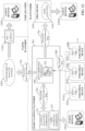
- FIG. 1 is a block diagram of an example industrial environment 100.
- a number of industrial controllers 118 are deployed throughout an industrial plant environment to monitor and control respective industrial systems or processes relating to product manufacture, machining, motion control, batch processing, material handling, or other such industrial functions.
- Industrial controllers 118 typically execute respective control programs to facilitate monitoring and control of industrial devices 120 making up the controlled industrial assets or systems (e.g., industrial machines).
- One or more industrial controllers 118 may also comprise a soft controller executed on a personal computer, on a server blade, or other hardware platform, or on a cloud platform.
- Some hybrid devices may also combine controller functionality with other functions (e.g., visualization).
- control programs executed by industrial controllers 118 can comprise any conceivable type of code used to process input signals read from the industrial devices 120 and to control output signals generated by the industrial controllers, including but not limited to ladder logic, sequential function charts, function block diagrams, structured text, C++, Python, Javascript, etc.
- Industrial devices 120 may include input devices that provide data relating to the controlled industrial systems to the industrial controllers 118, output devices that respond to control signals generated by the industrial controllers 118 to control aspects of the industrial systems, or devices that act as both input and output devices.
- Example input devices can include telemetry devices (e.g., temperature sensors, flow meters, level sensors, pressure sensors, etc.), manual operator control devices (e.g., push buttons, selector switches, etc.), safety monitoring devices (e.g., safety mats, safety pull cords, light curtains, etc.), and other such devices.
- Output devices may include motor drives, pneumatic actuators, signaling devices, robot control inputs, valves, and the like.
- Some industrial devices, such as industrial device 120M may operate autonomously on the plant network 116 without being controlled by an industrial controller 118.
- Industrial controllers 118 may communicatively interface with industrial devices 120 over hardwired connections or over wired or wireless networks.
- industrial controllers 118 can be equipped with native hardwired inputs and outputs that communicate with the industrial devices 120 to effect control of the devices.
- the native controller I/O can include digital I/O that transmits and receives discrete voltage signals to and from the field devices, or analog I/O that transmits and receives analog voltage or current signals to and from the devices.
- the controller I/O can communicate with a controller's processor over a backplane such that the digital and analog signals can be read into and controlled by the control programs.
- Industrial controllers 118 can also communicate with industrial devices 120 over the plant network 116 using, for example, a communication module or an integrated networking port.
- Exemplary networks can include the Internet, intranets, Ethernet, EtherNet/IP, DeviceNet, ControlNet, Data Highway and Data Highway Plus (DH/DH+), Remote I/O, Fieldbus, Modbus, Profibus, wireless networks, serial protocols, and the like.
- the industrial controllers 118 can also store persisted data values that can be referenced by the control program and used for control decisions, including but not limited to measured or calculated values representing operational states of a controlled machine or process (e.g., tank levels, positions, alarms, etc.) or captured time series data that is collected during operation of the automation system (e.g., status information for multiple points in time, diagnostic occurrences, etc.).
- some intelligent devices including but not limited to motor drives, instruments, or condition monitoring modules - may store data values that are used for control and/or to visualize states of operation. Such devices may also capture time-series data or events on a log for later retrieval and viewing.
- HMIs human-machine interfaces
- Industrial automation systems often include one or more human-machine interfaces (HMIs) 114 that allow plant personnel to view telemetry and status data associated with the automation systems, and to control some aspects of system operation.
- HMIs 114 may communicate with one or more of the industrial controllers 118 over a plant network 116, and exchange data with the industrial controllers to facilitate visualization of information relating to the controlled industrial processes on one or more pre-developed operator interface screens.
- HMIs 114 can also be configured to allow operators to submit data to specified data tags or memory addresses of the industrial controllers 118, thereby providing a means for operators to issue commands to the controlled systems (e.g., cycle start commands, device actuation commands, etc.), to modify setpoint values, etc.
- commands e.g., cycle start commands, device actuation commands, etc.
- HMIs 114 can generate one or more display screens through which the operator interacts with the industrial controllers 118, and thereby with the controlled processes and/or systems.
- Example display screens can visualize present states of industrial systems or their associated devices using graphical representations of the processes that display metered or calculated values, employ color or position animations based on state, render alarm notifications, or employ other such techniques for presenting relevant data to the operator. Data presented in this manner is read from industrial controllers 118 by HMIs 114 and presented on one or more of the display screens according to display formats chosen by the HMI developer.
- HMIs may comprise fixed location or mobile devices with either user-installed or pre-installed operating systems, and either user-installed or pre-installed graphical application software.
- Some industrial environments may also include other systems or devices relating to specific aspects of the controlled industrial systems. These may include, for example, one or more data historians 110 that aggregate and store production information collected from the industrial controllers 118 and other industrial devices.
- Industrial devices 120, industrial controllers 118, HMIs 114, associated controlled industrial assets, and other plant-floor systems operate on the operational technology (OT) level of the industrial environment.
- Higher level analytic and reporting systems may operate at the higher enterprise level of the industrial environment in the information technology (IT) domain; e.g., on an office network 108 or on a cloud platform 122.
- Such higher level systems can include, for example, enterprise resource planning (ERP) systems 104 that integrate and collectively manage high-level business operations, such as finance, sales, order management, marketing, human resources, or other such business functions.
- Manufacturing Execution Systems (MES) 102 can monitor and manage control operations on the control level given higher-level business considerations.
- Reporting systems 106 can collect operational data from industrial devices on the plant floor and generate daily or shift reports that summarize operational statistics of the controlled industrial assets.
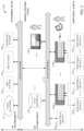
- FIG. 2a is a flow diagram illustrating a typical big data analysis approach.
- data from multiple industrial data sources 202 is streamed to big data storage (e.g., a data lake or database).
- big data storage e.g., a data lake or database.
- High-level analytics - such as AI, machine learning, statistical analysis, or another data science approach - are applied to these large and disparate sets of data until useful correlations and actionable insights are discovered.
- These actionable insights may be in the form of business outcomes, recommendations for minimizing or predicting machine downtime events, recommendations for minimizing energy utilization, recommendations for maximizing product throughput, or other such business goals.
- Big data analytics can yield insights into these desired business outcomes by discovering correlations between machines, devices, plant-floor events, sensor inputs, and other measurable factors represented by the aggregated sets of big data.
- an oil and gas company is likely to generate large amounts of data from compressors alone, which can produce 500 gigabytes of data per day in some cases, yielding data volumes in excess of a petabyte in one year.
- FIG. 2a can lead to discovery of new insights from learned correlations between large data sets, this approach can also produce relatively few insights relative to the large amount of data being stored and processed.
- analytic approach illustrated in FIG. 2a can identify valid and useful correlations between data sets
- big data analytic systems may also identify spurious, misleading, or unhelpful correlations between data sets. Humans are therefore ultimately required to determine whether a correlation learned by the analytic system is valid, and why this relationship exists. Applying this human expertise to analytic results at the back end of the analytic process, by submitting results produced by the AI analytics to an industry expert for review or verification, can result in a considerable amount of analytic processing and data storage wasted on producing spurious results.
- one or more embodiments also provide tools at the device level, the gateway level, and/or the cloud level that allow users to subscribe to data subsets of interest using an industrial publish-subscribe approach.
- tools can include smart tag support at the industrial device level that allows selected data items (e.g., smart tags, automation objects representing industrial assets that serve as building blocks for control programming, etc.) to be labeled according to analytic or business topics to which the data items relate (e.g., Quality, Energy Consumption, Product Throughput, Machine Runtime, etc.).
- These labeled data sets can be streamed from the lower device levels to higher broker or analytic levels, and users or high-level analytics systems can subscribe to selected data streams of interest according to the label associated with the data streams.
- FIG. 2b is a flow diagram illustrating this general analytic approach. Rather than collecting, storing, and analyzing all raw data available from an industrial enterprise (or unnecessarily large sets of this available data), as in the approach depicted in FIG.
- analysis and actions that relate to real-time operation of industrial machines can be implemented on an edge device (e.g., a network infrastructure device that communicatively links the plant network to external networks or systems) and acted upon at the machine level, without the involvement of a higher-level system to determine the necessary control actions.
- an edge device e.g., a network infrastructure device that communicatively links the plant network to external networks or systems
- Smart gateway platform 302 can include a device interface component 304, a model configuration component 306, a data modeling component 308, a gateway analytics component 310, an analytics interface component 312, a user interface component 314, one or more processors 316, and memory 318.
- one or more of the device interface component 304, model configuration component 306, data modeling component 308, gateway analytics component 310, analytics interface component 312, user interface component 314, the one or more processors 316, and memory 318 can be electrically and/or communicatively coupled to one another to perform one or more of the functions of the smart gateway platform 302.
- components 304, 306, 308, 310, 312, and 314 can comprise software instructions stored on memory 318 and executed by processor(s) 316.
- Smart gateway platform 302 may also interact with other hardware and/or software components not depicted in FIG. 3 .
- processor(s) 316 may interact with one or more external user interface devices, such as a keyboard, a mouse, a display monitor, a touchscreen, or other such interface devices.
- smart gateway platform 302 can serve as a logical entity that is embedded in another device, including but not limited to an edge device, an industrial controller, or an HMI terminal.
- Model configuration component 306 can be configured to generate an analytic model that can be leveraged by an AI or machine learning analytic system in connection with applying suitable analytics for achieving a desired business objective.
- the analytic model can be generated based on a model template - selected from a library 320 of model templates stored on memory 318- that encodes domain expertise relevant to the business objective.
- the model template can define data items (e.g., sensor inputs, measured process variables, key performance indicators, machine operating modes, environmental factors, etc.) that are relevant to the business objective, as well as correlations between these data items.
- Model configuration component 306 can transform this model template to a customized model based on user input that maps the generic data items defined by the model template to actual sources of the data discovered by the device interface component 304.
- Gateway analytics component 310 can be configured to perform local analytics (e.g., AI, machine learning, statistical analysis, etc.) on the modeled industrial data.
- Analytics interface component 312 can be configured to interface and exchange data with external systems that consume this data to extract business value (e.g., AI systems, machine learning systems, data lakes etc.). This can include sending the modeled industrial data to these external analytic systems or sending results of local analytics performed by the gateway analytics component 310.
- the one or more processors 316 can perform one or more of the functions described herein with reference to the systems and/or methods disclosed.
- Memory 318 can be a computer-readable storage medium storing computer-executable instructions and/or information for performing the functions described herein with reference to the systems and/or methods disclosed.
- one or more of the program execution component 404, I/O control component 406, smart tag configuration component 408, data publishing component 410, networking component 412, user interface component 414, the one or more processors 418, and memory 420 can be electrically and/or communicatively coupled to one another to perform one or more of the functions of the industrial device 402.
- components 404, 406, 408, 410, 412, and 414 can comprise software instructions stored on memory 420 and executed by processor(s) 418.
- Industrial device 402 may also interact with other hardware and/or software components not depicted in FIG. 4 .
- processor(s) 418 may interact with one or more external user interface devices, such as a keyboard, a mouse, a display monitor, a touchscreen, or other such interface devices.
- Smart tag configuration component 408 can be configured to set metadata values or labels associated with smart tags defined for the industrial device 402 based on metadata configuration input data.
- industrial device 402 in addition to standard general data types (e.g., real, analog, digital, etc.), industrial device 402 is configured to support smart tags 422 corresponding to industrial-specific data types.
- Smart tags 422 have associated metadata that can be configured by the user via smart tag configuration component 408 in order to customize the data tags for a given industrial application.
- Smart tags 422 can also have associated metadata that contextualizes data associated with the tag 422 based on industrial or user expertise in ways that facilitate business-driven analytics, as will be described in more detail herein, effectively pre-modeling the data at the device level.
- user interface component 414 can be configured to generate and serve suitable graphical interface screens to a client device, and exchange data via these graphical interface screens.
- Input data that can be received via user interface component 414 can include, but is not limited to, user-defined control programs or routines, data tag definitions, smart tag metadata configurations, or other such data.
- the one or more processors 418 can perform one or more of the functions described herein with reference to the systems and/or methods disclosed.
- Memory 420 can be a computer-readable storage medium storing computer-executable instructions and/or information for performing the functions described herein with reference to the systems and/or methods disclosed.
- analytic approach implemented by embodiments of the smart gateway platform 302 leverages industry domain expertise to reduce the data space over which AI analytics are to be applied by explicitly defining the data items known to be relevant to a given business objective (e.g., reduction of machine downtime, reduction of specified machine failures such as paper web breaks, optimization of energy utilization by a specified type of industrial machine, improvement of quality of a particular type of product, etc.).
- Known correlations and/or causalities between these relevant data items - also drawn from domain expertise - are also predefined and modeled into the data, thereby applying useful analytic constraints that lead to a desired insight more quickly and with less processing overhead relative to applying unconstrained big data analysis over unnecessarily large data sets.
- This domain expertise is encoded in the form of model templates stored on the smart gateway platform 302.
- FIG. 5 is a diagram illustrating selection and configuration of a model template 502 designed to model industrial data for subsequent AI analysis.
- smart gateway platform 302 can store a library 320 of model templates 502 that are each associated with a corresponding business objective or outcome.
- Example business objectives can include, but are not limited to, reduction in total machine downtime or number of machine failures; minimization of machine power consumption; optimization of operational efficiency (e.g., amount of machine output relative to an amount of energy consumed by the machine); minimization of emissions; improvement of product quality; identification of factors that yield maximum product output, minimal machine downtime, or maximum product quality; or other such objectives.
- a Tire and Rubber sub-industry may be associated with several different machines that are typically associated with tire manufacture (e.g., Calendering, Extrusion, Curing Press, Tire Building Machine, Tire Picking Station, etc.).
- Each machine is associated with one or more predefined business objectives related to the selected machine.
- Some business objectives may be relatively high level and global objectives, such as minimization of machine downtime or failures, maximization of throughput, minimization of energy consumption, optimization of machine efficiency, etc.
- Other objectives may be specific or unique to the selected machine and vertical.
- such relationships between related data tags can be defined within smart tag metadata to effectively yield a device-level model that can be leveraged by external analytic systems (e.g., AI analytic systems or traditional analytic systems) in order to quickly learn insights into the associated industrial process or machine operation.
- external analytic systems e.g., AI analytic systems or traditional analytic systems
- these device-level models - encoded by the smart tags and their associated metadata - can define complex correlations and relationships between data tags.
- Some embodiments of data modeling component 308 can further model at least some of the raw data and smart data to conform to an object-oriented asset model if appropriate.
- Industrial plants typically operate many common industrial assets, including pumps, boilers, and compressors. Many such assets are deployed within the plant, and in some cases there may be many types and models of these assets. Some asset types can be described hierarchically.
- FIG. 10 is an example asset type hierarchy 1002 for industrial pumps. Pumps can be categorized according to two different types of pumps - dynamic and positive displacement. Dynamic pumps can be either centrifugal or special effect. Centrifugal pumps can be axial flow, mixed flow, or peripheral. A common type of centrifugal pump is an electrical submersible pump.
- FIG 11 depicts data 704 being fed to an AI analytic system 1102, other types of analytics can be applied to the data 704 without departing from the scope of this disclosure, including but not limited to machine learning or statistical analysis.
- model 702 has been customized by mapping the model's defined data items to specific data items on the industrial devices (e.g., smart tags 422 and/or standard data tags 508), the smart gateway platform 302 begins collecting and transforming the data from the mapped data sources as described above to yield structured and contextualized data 704.
- Informing AI analytic system 1102 of relevant data correlations and causalities between the data items prior to application of data analytics can apply useful constraints on data analysis performed by the AI analytic system 1102. These constraints can drive the analytic system 1102 to useful insights more quickly relative to unconstrained big data analysis, significantly reducing the amount of time required for the AI analytic system 1102 to discover insights and generate useful recommendations relative to the desired business objective. These predefined correlations and causalities can also mitigate discovery of spurious or irrelevant correlations between the data items by the AI analytic system 1102.
- This structured and contextualized data 704 is fed to AI analytic system 1102 (e.g., as streaming smart data), which performs AI or machine learning analysis on the smart data streams with the goal of determining root causes of productivity loss and generating recommended countermeasures or actionable insights.
- AI analytic system 1102 e.g., as streaming smart data
- reduction of the relevant data set by the smart gateway platform 302 to those data items known to be relevant to the business objective, as well as the known correlations and causalities between the data items encoded into the smart data based on model 702 can lead the AI analytic system 1102 more quickly to actionable insights regarding the defined business objective.
- AI analytic system 1102 may also identify indications within the data 704 that typically precede a downtime event, and continue monitoring the structured and contextualized data 704 for the presence of these indications. In response to determining that relevant items of data 704 satisfy the criteria indicating an impending downtime event, the analytic system 1102 may generate and deliver a notification to one or more client devices 1106 informing of the predicted downtime event.
- higher level analytics may be best suited for execution in the IT domain; e.g. by enterprise-level analytic systems 1302 or cloud-based analytics systems 1204.
- Analytics in the IT or cloud domain typically produce higher-level insights for visualization on client devices using dashboards or other visual presentations.
- Such higher-level analytics are referred to as non-real-time analytics since they do not typically result in immediate feedback control of industrial assets.
- Non-real-time analytics may also be referred to as human real-time analytics, as opposed to machine real-time analytics.
- a majority of data processing and value extraction is likely to occur in the OT environment.
- most of the data processing may instead occur on the cloud platform 122.
- the example architecture depicted in FIG. 13 can be divided into three hierarchical levels: the device level, the system level, and the enterprise level.
- the enterprise level is part of the IT environment, while the device and system levels are part of the OT environment.
- Device-level analytics can perform such real-time functions as checking measured operating parameters against defined limits, which can provide useful insights into a device's operation.
- System-level analytics e.g., performed by edge-level analytic system 1210 or gateway analytics component 310) can derive insights relating to higher-level system operation, such as predicting that a trend in a paper web's tension is indicative of an impending web break within a few operating cycles.
- Operational insights obtained by device-level and system-level analytics when implemented in controllers and industrial computers, enable real-time control actions intended to move system performance toward the business objective associated with model 702.
- real-time analytics result from processing real-time data in the OT environment.
- selected contextualized or smart data from the OT environment can be analyzed and combined with data from other parts of the industrial enterprise to develop data presentations (e.g., dashboards or other visual presentations) that deliver actionable insights to a user via a client device.
- This approach of locating data processing and analytics functions in a scalable manner is well-suited to industrial Internet-of-Things (IoT) applications with varying time domains of processing (e.g., milliseconds, seconds, minutes, hours, etc.), asset locations (centralized and remote), and system relationships (e.g., autonomous, in-line, buffered, batched, etc.).
- IoT Internet-of-Things
- Analytics and AI/machine learning at each of these three defined levels can optimize processes and operations in industrial plants to achieve desired business objectives.
- a device-level or system-level analytic system can perform analytics on the device or system level when appropriate (e.g., on industrial controllers or other industrial devices 402, on low-level industrial devices 120, on edge devices 1206, etc.), and can shift analytics tasks to enterprise-level analytics systems to perform analytics scoped to the enterprise level as needed.
- Device-level analytic systems 1304 can perform local analytics on device data when device-level results are required.
- Device-level analytics performed by analytic systems 1304 can include, but are not limited to, determining whether a particular industrial device (e.g., a controller, sensor, drive, meter, etc.) is at risk of failure or should be replaced based on analysis of local data associated with that device (or data associated with a process or machine controlled by the device), determining a root cause of a device fault, etc.
- a particular industrial device e.g., a controller, sensor, drive, meter, etc.
- Device-level analytic systems 1304 can also leverage the data modeling templates 424 and device-level models represented by smart tags 422 to optimize real-time operation.
- a production line may take some time to transition back to normal operation after being restarted due to the amount of time required for the line to rebalance.
- the time required for the line to rebalance itself and return to its normal workflow can adversely impact the line's overall equipment effectiveness (OEE).
- a template 424 may define a data modeling for optimizing production line start-up.
- the template 424 can identify, for example, which subset of available data elements (e.g., smart tags 422) drive optimization of line start-up and the relationships between these data elements.
- the resulting device-level data modeling can be used by device-level analytic systems 1304 at the controller to determine an optimal start-up sequence that minimizes the time required to resume normal line operation.
- Driving computing services down to the lower levels of the architecture in this manner - using the device-level models to aid local analytics - can reduce communication bandwidth by performing optimization analytics at the device level rather than sending the data to higher level optimization systems.
- This approach can also reduce latency, making control-level analytics applications possible (e.g., identifying pump cavitation in a drive, making it possible to rapidly trim the pump speed).
- Results of the device-level analytics can be consumed locally by the industrial device itself, or sent to a client device (e.g., as a notification or dashboard).
- a client device e.g., as a notification or dashboard.
- analytic system 1304 in response to a determination by a device-level analytic system 1304 that an industrial controller or device that hosts the analytic system 1304 is at risk of failure or an unacceptable loss of efficiency, and if the analytic system 1304 identifies an automated countermeasure that may mitigate or delay the device failure, analytic system 1304 can generate a control instruction that implements the countermeasure on the host device; e.g., by altering the device's operation in a manner that has a likelihood of mitigating the failure.
- Such countermeasures can include, but are not limited to, switching the device to a slow operation mode or stopped mode, switching the device to a backup power supply, changing a setpoint defined in the device, initiating execution of a different control program or sub-routine (in the case of industrial controllers or other programmable devices), or other such countermeasures.
- system-level analytic systems 1210 or 310 risks associated with operation of more complex industrial automation systems - rather than a single device - can be monitored and identified, and appropriate countermeasures scoped to the entire automation system can be implemented.
- a system-level analytic system 1210 or 310 predicts - based on analysis of structured and contextualized data 704 prepared by the smart gateway platform 302 - that a production line is at risk of producing an excessive amount of product waste (e.g., due to an increase in the number of part rejections, a discovered inefficiency in a process carried out by the production line, an indication of excessive wear on one or more devices that carry out the process, etc.)
- the system-level analytic system 1210, 310 can implement a multi-device countermeasure intended to mitigate the risk of product waste.
- Such system-wide countermeasures can include, for example, reducing the rate of production on a production line, switching production of the product to an alternative production line (which may involve sending instructions to control devices of the current production line to cease production, sending further instructions to the new production line to begin production, and sending still further instructions to appropriate upstream systems to begin providing material or parts to the new production line), sourcing a production line with parts from an alternate production line or source, or other such countermeasures.
- edge device 1206 can be configured to time-stamp data from the adjacent device-layer, ensuring accurate synchronization of data from the disparate devices.
- device-level, edge-level, and system-level analytic systems can also send analytic results to authorized client devices in the form of notifications, dashboards, or other graphical interfaces.
- the device-level, edge-level, or system-level analytic systems can send results of local analytics to the enterprise-level analytic system 1302 or cloud-based analytic system 1204 for enterprise level analysis.
- the device-level, edge-level, and system-level analytic systems can also send results of local analytics to other analytic systems on the same level or a different level of the enterprise. Analytic results sent from one of the analytic systems to another can be processed at the receiving system for further analytics.
- multi-level analytic systems can carry out inter-node collaborative analysis in connection with performing plant-level analytics, such that analytical tasks are carried out at the level of the enterprise deemed most suitable for the given analytical task.
- Analytics can also be scaled downward from higher levels to lower levels as appropriate.
- the decision to scale analytics upward or downward between analytic systems can be based on time-sensitivity of the analytics being performed. For example, if a system-level analytic system (e.g., edge-level analytic system 1210 or gateway analytics component 310) is performing analysis on a current production run of a product in which the result of the analytics may determine how the current run is to be executed, the system-level analytic system may shift at least a portion of the analytic processing to a device-level analytic system 1304 hosted on an industrial controller or another industrial device 402 that is part of the automation system executing the production run.
- a system-level analytic system e.g., edge-level analytic system 1210 or gateway analytics component 310
- the system-level analytic system may shift at least a portion of the analytic processing to a device-level analytic system 1304 hosted on an industrial controller or another industrial device 402 that is part of the automation system executing the production run.
- analytic systems can be configured to identify criteria indicating that data or analytic results are to be scaled or transferred to another analytic system; namely, the particular device, group of devices, industrial assets, or systems affected by a result of the analysis.
- the decision to send analytic results or other locally available data to another analytic system can be based on a determination of whether the result or data satisfies a criterion indicative of an importance or relevance of the result or data to another portion or layer of the overall enterprise architecture.
- industrial devices 402 that support smart tags 422 and associated device-level data modeling can allow their device-level data models to be discovered and integrated into higher-level analytic models.
- device-level templates 424 or other device-level models on the industrial devices 402 can be discovered by higher-level systems (e.g., analytic systems 1210, 1204, or 1302, ERP systems, maintenance systems, etc.) and integrated into high-level analytic models associated with these systems.
- smart tags 422 and their associated modeling metadata implement data engineering at the device level with the assistance of the modeling templates 424, and the resulting device-level data models can be discovered by and pulled into higher-level systems without requiring manual configuration. Modeling data at the device layer in this way can facilitate automated integration into these higher-level systems in a manner that is agnostic to the type of system consuming the data. Smart tags 422 can also simplify integration of distributed analytic architectures by defining the input/output structures for communication between distributed systems and analytics engines.
- smart tag modeling contextualizes data at low levels, and this contextualization is maintained - and enhanced - as the data moves to higher levels of the enterprise.
- a smart tag 422 associated with a pump or other industrial asset can be modeled in a controller with contextual metadata based on information available at the controller (e.g., relationships to other data tags as defined by the templates 424, timestamps, device-level context, environmental data, etc.).
- the smart tag's data and associated contextual metadata can be supplemented with maintenance data or other information available at the higher levels, thereby enhancing the data model as the data moves upward.
- Summing and contextualizing data at the lowest layers - e.g., the device layers - can ease integration of data with higher-level systems by removing the burden of learning correlations and contexts from these high-level systems.
- Propagating these device-level model - as represented by the device-level contextual metadata - to higher levels can also allow the device-level models to be consumed by these higher levels without the need to push data down to the device level for analysis.
- This general approach can be used to progressively add layers of contextualization to industrial data as the data moves upward through the enterprise hierarchy.
- the gateway platform 302 receives modeled industrial data from the smart tags 422 of industrial devices - that is industrial data enhanced with device-level contextual metadata added by the industrial devices based on data modeling templates 424 - the gateway platform's data modeling component 308 can further enhance the device-level model by supplementing the device-level contextual metadata with further modeling metadata based on the selected model template 502 for a desired business objective.
- Analytics can then be performed on the resulting modeled data based on this aggregate data model.
- the progressively modeled data - comprising the industrial data values, their associated device-level contextual metadata, and the further modeling metadata added by the gateway platform's modeling component 308 - can be analyzed by the gateway platform's gateway analytics component 310.
- the gateway platform's analytics interface component 312 may send the progressively modeled data to another analytic system for analysis (e.g., a cloud-based analytic system, an enterprise-level analytic system, an edge-level analytic system, etc.).
- this progressive, layered data modeling can be leveraged by the analytic system quickly and accurately yield actionable insights into the controlled industrial process relative to defined business objectives for which the models were designed.
- the AI engine (or the data modeling component 308 in the case of the gateway platform 302) can adjust the data model structures of the smart tags to encode this key variable as part of the smart tag architecture; e.g., by adding a new data field defining a key variable to be monitored, or by modifying the device-level modeling templates 424 to reflect the new insight discovered at the higher-level analytic system or gateway platform 302.
- discoveries made by external or higher-level analytic systems are permanently encoded in the metadata of the relevant smart tags 422 at the device level, and this knowledge can be accessed by other analytic systems that reference the smart tags 422.
- data collected by the smart gateway platform 302 for transformation and transmission to the cloud-based AI analytic system 1204 includes real-time control data 1414 generated by industrial devices 402.
- This real-time control data can include analog and digital data stored in the devices' data tables or associated with the devices' data tags.
- the control data can represent, for example, measured telemetry or sensor values read from a controlled industrial process (e.g., temperatures, pressures, flows, levels, speeds, etc.), measured digital values (e.g., part present sensor values, safety device statuses, switch settings, etc.), controlled analog and digital output values generated by the devices 402 and directed to industrial output devices of the controlled system, calculated performance metrics, etc.
- mapping data is received at the smart gateway platform that maps the data items defined by the model template selected at step 1502 to respective data tags on one or more industrial devices.
- the data tags to which the data items are mapped may be standard industrial data tags or may be smart tags that store smart data that has been pre-contextualized by its associated smart industrial device.
- Such smart devices may be configured to pre-contextualize data items generated by the device with contextualization metadata that provides additional information regarding the context under which the data values were generated.
- This contextualization metadata may include, for example, an operating state of a machine at the time the data value was generated (e.g., running, idle, faulted, etc.), power statistics at the time the data was generated (e.g., voltages, currents, power consumption, etc.), or other such contextual metadata that may impart greater informational value to the data item.
- Device interface component 1604 can be configured to receive or obtain data streams from industrial devices (e.g., industrial devices 402).
- this data can comprise contextualized data that has been pre-modeled at the industrial device 402; e.g., by metadata associated with smart tags 422, from which the data is sourced, as described above.
- the data streams include both data values associated with their corresponding data tags (e.g., time-series data) as well as pre-defined and learned correlations with other data tags or values which can assist AI systems to converge to actionable insights faster relative to uncorrelated data streams.
- the data streams received from the industrial devices may also be labeled according to one or more topics to which the data is relevant from an analytics perspective.
- the data streams may be published by the respective devices by data publishing components 410 associated with the devices in some embodiments, and can be received by device interface component 1604 via one or more secure network connections (e.g., a plant network, a cloud platform, public networks such as the internet, etc.).
- secure network connections e.g., a plant network, a cloud platform, public networks such as the internet, etc.
- Analytic system interface component 1606 can be configured to exchange data between the broker system 1602 and external analytic systems (e.g., analytic system 1102). This can include receiving requests from these external systems to subscribe to one or more labeled data streams, and publishing of selected data streams to respective analytic systems in accordance with the subscriptions.
- Data stream publishing component 1608 can be configured to process data topic subscription requests from analytics systems (e.g., AI analytic systems, machine learning systems, etc.), and to selectively publish data streams to subscribing analytic systems according to topic.
- FIG. 17 is a diagram illustrating configuration of smart tags in a tag database 1702 of an industrial device 402 that supports smart tags.
- Industrial device 402 may be, for example, an industrial controller (e.g., a programmable logic controller or other type of programmable automation controller) configured to execute an industrial control program 1704 to facilitate monitoring and control of an industrial machine or process.
- Industrial device 402 includes a tag database 1702 that stores data tag definitions 1714, which may include definitions of both standard data tags and smart tags 422.
- a user can configure both the control program 1704 and the data tag definitions 1714 using a device configuration application 1708 that executes on a client device 1710 (e.g., a laptop computer, a desktop computer, a tablet computer, etc.) that is communicatively interfaced to the industrial device 402.
- client device 1710 can interface with the industrial device 402 over a hard-wired connection (e.g. a universal serial bus connection, an Ethernet connection, a serial connection, etc.) or over a wireless connection (e.g., near-field, WiFi, etc.) supported by user interface component 414.
- Device configuration application 1708 can execute a program development environment that can be used to develop control program 1704 and its associated data tags, including any smart tags 422 to be associated with one or more industrial assets to be controlled using control program 1704.
- smart tags 422 included in the tag definitions 1714 can comprise metadata that pre-models and contextualizes the data for subsequent AI or machine learning analysis. At least some of this contextualization metadata can be based on predefined data modeling templates 424 as described above, such that the metadata defines relationships, correlations, and preferred analysis types to be performed on the smart tag data as gleaned from industry expertise encoded in the templates 424. Some of the contextualization metadata may also comprise user-defined contextualization set by a user as part of the smart tag configuration data 1706. Such user-defined contextualization may define customized relationships or correlations between data items to yield customized device-level models that conform to idiosyncrasies of the end user's particular industrial automation systems and equipment.
- the user can also configure the metadata associated with respective smart tags 422 to define pre-processing to be performed on the smart tag's data at the device level in accordance with a given industrial application. For example, for a smart tag 422 that defines a state of a bottle filling machine to be controlled by industrial device 402, the user may specify the various states to be represented by the tag (e.g., Running, Home, Abnormal, Idle, etc.).
- the smart tag configuration component 408 can support a number of pre-defined states that can be selected by the user and associated with a given smart tag 422 representing a machine or device state.
- the user can define the names of one or more of the states to be associated with the smart tag 422.
- a smart tag 422 representing a velocity of a conveyor that feeds bottles to the filling machine
- the user can specify maximum and minimum values for the velocity value. Accordingly, the smart tag 422 will not generate a velocity value that is outside the range defined by the specified maximum and minimum values, and may generate an error or alarm output if the measured velocity value exceeds the defined maximum or falls below the defined minimum.
- Another smart tag 422 representing an average temperature may be configured to average multiple analog temperature input values specified by the user in the metadata.
- users can also associate selected smart tags 422 with a topic label indicative of a topic to which the associated data is relevant.
- device configuration application 1708 can include configuration tools that allow the user to associate selected tags with relevant topic labels, which are submitted as part of smart tag configuration data 1706.
- Example topics with which smart tags can be associated can include, but are not limited to product quality, energy consumption, product throughput, machine runtime, machine downtime, or other such topics.
- smart tags 422 can be pre-labeled at the device layer according to relevant topics and published to their own channel (or multiple different relevant channels).
- the exemplary broker system 1602 can publish the received data streams 1802 to their own channels, and allows users or external systems - including analytic systems such as AI analytic system 1102 - to subscribe to selected channels of interest according to topic.
- an analytic system 1102 that seeks to optimize product quality of a given manufacturing line can submit subscription data 1804 to the broker system 1602 requesting to subscribe to a subset of available data streams having the Quality topic label.
- smart tags 422 and their associated data streams 1802 labeled with the Quality topic can encompass data that should be run through machine learning in order to optimize product quality. As described above, these tags can be pre-defined in the industrial devices 402 based on domain expertise as to which data values should be monitored or optimized to achieve best quality.
- interaction diagram(s) may represent methodologies, or methods, in accordance with the subject disclosure when disparate entities enact disparate portions of the methodologies.
- two or more of the disclosed example methods can be implemented in combination with each other, to accomplish one or more features or advantages described herein.
- Drawing import component 2006 can import the CAD file 2106 (or other type of engineering drawing data) for processing by the program generation component 2008.
- CAD file 2106 may be developed using a separate engineering drawing application, and a system designer can import the CAD file 2106 into the program development system 2002 using interactive import tools provided by the program development environment.
- program development system 2002 may be a subsystem of a comprehensive design platform that supports parallel development of engineering drawings and control programming within the same development environment.
- the CAD file 2106 can be shared between the drawing development platform and the program development system within the same development environment.
- Program generation component 2008 can also identify relationships between these identified devices, machines, and industrial assets based on further analysis of the drawings. As part of this analysis, program generation component 2008 can identify different representations of the same elements (e.g., industrial assets, machines, and devices) across different drawings. For example, the electrical I/O drawings can be analyzed to identify input and output devices in the field (e.g., solenoid valves, pneumatic actuators, motor contactors, push buttons, proximity switches, photodetectors, telemetry devices, motor drives, etc.) that are electrically connected to the I/O of the industrial device 402 (e.g., industrial controller) to be programmed, as well as the I/O addresses associated with each connected input or output device. Program generation component 2008 can also identify physical or functional relationships between these input and output devices, or between these devices and other machines or assets, based on analysis of the mechanical drawings in which these devices and assets are represented.
- the electrical I/O drawings can be analyzed to identify input and output devices in the field (e.g., solenoid valves
- program generation component 2008 can customize the code segment 2208 as needed to accurately integrate the code segment 2208 into the designer's system-specific control program 1704.
- a code segment 2208 stored in the code segment library may use generic placeholders within the code segment programming in place of application-specific digital and analog data tags or I/O addresses whose values correspond to the industrial controller's inputs and outputs.
- An automation object 2206 for a given type of industrial asset can encode such aspects as 2D or 3D visualizations, alarms, control coding (e.g., logic or other type of control programming), analytics, startup procedures, testing protocols, validation reports, simulations, schematics, security protocols, and other such properties associated with the industrial asset 2302 represented by the object 2206.
- Automation objects 2206 can also be geotagged with location information identifying the location of the associated asset.
- the automation object 2206 corresponding to a given real-world asset 2302 can also record status or operational history data for the asset.
- program generation component 2008 may determine that the automation system includes a conveyor based on analysis of the mechanical and/or electrical drawings included in the CAD files 2106. Based on this determination, the program generation component 2008 can generate control programming for controlling this conveyor (e.g., by selecting an appropriate pre-defined code segment 2208 for conveyor control, or by generating the control code by other means), and can also generate a smart tag 422 (e.g., a rate data tag 804 as discussed above in connection with FIG. 8 ) representing the velocity of the conveyor. The program generation component 2008 can link this smart tag 422 to the appropriate analog input corresponding to the conveyor's velocity signal, as determined based on analysis of the I/O drawings.
- control programming for controlling this conveyor (e.g., by selecting an appropriate pre-defined code segment 2208 for conveyor control, or by generating the control code by other means), and can also generate a smart tag 422 (e.g., a rate data tag 804 as discussed above in connection with FIG. 8 ) representing the velocity of the conveyor.
- the program generation component 2008 can
- Program generation component 2008 packages or compiles the resulting control program 1704 and associated tag definitions 1714 into a control program file 2202 that can be exported to and executed on a target industrial device 402 (e.g., an industrial controller) for execution.
- FIG. 24 illustrates export of the resulting control program file 2202 to an industrial device 402.
- program export component 2010 can export or download the program file 2202 to a target industrial device 402 for storage and execution.
- Execution of the control program file 2202 on the industrial device causes a tag database (e.g., similar to tag database 1702 depicted in FIG. 17 ) to be created on the industrial device 402 in accordance with the tag definitions 1714, and programs the industrial device 402 in accordance with the control program 1704.
- a tag database e.g., similar to tag database 1702 depicted in FIG. 17
- program export component 2010 can also export, to the industrial device 402, the one or more data modeling templates 424 that were used by the program development system 2002 to model and contextualize the smart tags 422.
- program development system 2002 may interface with the industrial device 402 via a direct communicative connection between the system 2002 and the device 402, or via one or more networks (e.g., a plant network).
- the program export component 2010 may export the program file via a secured public or private network accessible to the cloud platform and the industrial device 402.
- the program generation techniques described above can be used to generate multiple control program files 2202 for respective multiple industrial controllers that are part of a common automation system or collection of automation systems represented by the CAD files 2106. For example, if program generation component 2008 determines that multiple industrial controllers are represented in the CAD files 2106, with each controller being responsible for monitoring and controlling a subsystem of a larger automation system or environment, program generation component 2008 can determine, for each identified controller, which portion of the automation system represented by the CAD files 2106 is monitored and controlled by that controller. Based on this information, the program generation component 2008 can generate a customized control program 1704 and associated tag definitions 1714 for each controller based on analysis of the subset of the CAD file data corresponding to the industrial assets that are to be monitored and controlled by that controller.
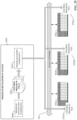
- FIG. 25 is a diagram illustrating deployment of multiple control program files 2202a-2202c to respective industrial controllers (industrial devices 402a-402c) by the program export component 2010 of the program development system 2002.
- the program export component 2010 deploys the respective control program files 2202 to the controllers via the plant network 116 on which the controllers reside.
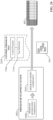
- FIG. 26 illustrates a methodology in accordance with one or more embodiments of the subject application. While, for purposes of simplicity of explanation, the methodology shown herein is shown and described as a series of acts, it is to be understood and appreciated that the subject innovation is not limited by the order of acts, as some acts may, in accordance therewith, occur in a different order and/or concurrently with other acts from that shown and described herein. For example, those skilled in the art will understand and appreciate that a methodology could alternatively be represented as a series of interrelated states or events, such as in a state diagram. Moreover, not all illustrated acts may be required to implement a methodology in accordance with the innovation.
- interaction diagram(s) may represent methodologies, or methods, in accordance with the subject disclosure when disparate entities enact disparate portions of the methodologies.
- two or more of the disclosed example methods can be implemented in combination with each other, to accomplish one or more features or advantages described herein.
- FIG. 26 illustrates an example methodology 2600 for generating industrial controller programming and associated smart tag definitions based on analysis of digital engineering drawings.
- the methodology 2600 can be implemented on a program development system that executes on a local client device, on a server or other type of computing system accessible to a client device, or on a cloud platform as a cloud-based service.
- one or more digital engineering drawings are received by an industrial program development system.
- the engineering drawings can represent at least one of mechanical or electrical aspects of an industrial automation system, and may comprise 2D mechanical drawings, a 3D mechanical model, electrical power distribution drawings, electrical I/O drawings, control panel layout drawings, P&ID drawings, or other such engineering drawings.
- industrial assets that make up the industrial automation system are identified based on analysis of the digital engineering drawings received at step 2602.
- the industrial program development system can identify one or more machines or other industrial assets that make up the system, including but not limited to conveyors, vats, ovens, mixers, machining stations, industrial robots, vision systems or other quality check systems, stamping presses, or other such assets.
- I/O devices that provide input signals to and receive output signals from an industrial controller that will be monitoring and controlling the industrial automation system are identified based on further analysis of the digital engineering drawings received at step 2602.
- Example input devices that can be identified in this manner can include, but are not limited to, photo-sensors, proximity switches, push-buttons, switches, safety input devices (e.g., light curtains, safety mats, etc.), telemetry devices (e.g., flow meters, temperature meters, pressure meters, fill level meters, etc.), or other such input devices.
- Example output devices that can be identified in this way can include, but are not limited to, solenoid valves, motor contactors or motor drives, actuators (e.g. pushers, stoppers, etc.), illuminated indicators, or other such output devices.
- a control program and associated smart tag definitions are generated by the program development system based on the identification of the industrial assets at step 2604, the identification of the I/O devices at step 2606, and the data modeling template selected at 2610.
- the system can infer the type of monitoring and control to be performed on the industrial assets identified at step 2604 based on the identities and relationships between the industrial assets, and generate portions of the control programming to perform this monitoring and control.
- the program development system can also determine appropriate I/O address referencing for the generated control programming based on I/O drawings submitted at step 2602.
- the program development system can generate a set of smart tags considered necessary to support the control program, and can also set contextualization metadata for these smart tags in accordance with the data modeling template selected at step 2610.
- Embodiments, systems, and components described herein, as well as control systems and automation environments in which various aspects set forth in the subject specification can be carried out can include computer or network components such as servers, clients, programmable logic controllers (PLCs), automation controllers, communications modules, mobile computers, on-board computers for mobile vehicles, wireless components, control components and so forth which are capable of interacting across a network.
- Computers and servers include one or more processors-electronic integrated circuits that perform logic operations employing electric signals-configured to execute instructions stored in media such as random access memory (RAM), read only memory (ROM), hard drives, as well as removable memory devices, which can include memory sticks, memory cards, flash drives, external hard drives, and so on.
- the term PLC or automation controller as used herein can include functionality that can be shared across multiple components, systems, and/or networks.
- one or more PLCs or automation controllers can communicate and cooperate with various network devices across the network. This can include substantially any type of control, communications module, computer, Input/Output (I/O) device, sensor, actuator, and human machine interface (HMI) that communicate via the network, which includes control, automation, and/or public networks.
- the PLC or automation controller can also communicate to and control various other devices such as standard or safety-rated I/O modules including analog, digital, programmed/intelligent I/O modules, other programmable controllers, communications modules, sensors, actuators, output devices, and the like.
- the network can include public networks such as the internet, intranets, and automation networks such as control and information protocol (CIP) networks including DeviceNet, ControlNet, safety networks, and Ethernet/IP. Other networks include Ethernet, DH/DH+, Remote I/O, Fieldbus, Modbus, Profibus, CAN, wireless networks, serial protocols, and so forth.
- the network devices can include various possibilities (hardware and/or software components). These include components such as switches with virtual local area network (VLAN) capability, LANs, WANs, proxies, gateways, routers, firewalls, virtual private network (VPN) devices, servers, clients, computers, configuration tools, monitoring tools, and/or other devices.
- VLAN virtual local area network
- WANs wide area network
- proxies gateways
- routers virtual private network
- VPN virtual private network
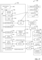
- FIGs. 27 and 28 are intended to provide a brief, general description of a suitable environment in which the various aspects of the disclosed subject matter may be implemented. While the embodiments have been described above in the general context of computer-executable instructions that can run on one or more computers, those skilled in the art will recognize that the embodiments can be also implemented in combination with other program modules and/or as a combination of hardware and software.
- program modules include routines, programs, components, data structures, etc., that perform particular tasks or implement particular abstract data types.
- inventive methods can be practiced with other computer system configurations, including single-processor or multiprocessor computer systems, minicomputers, mainframe computers, Internet of Things (IoT) devices, distributed computing systems, as well as personal computers, hand-held computing devices, microprocessor-based or programmable consumer electronics, and the like, each of which can be operatively coupled to one or more associated devices.
- IoT Internet of Things
- the illustrated embodiments herein can be also practiced in distributed computing environments where certain tasks are performed by remote processing devices that are linked through a communications network.
- program modules can be located in both local and remote memory storage devices.
- Computer-readable storage media or machine-readable storage media can be any available storage media that can be accessed by the computer and includes both volatile and nonvolatile media, removable and non-removable media.
- Computer-readable storage media or machine-readable storage media can be implemented in connection with any method or technology for storage of information such as computer-readable or machine-readable instructions, program modules, structured data or unstructured data.
- Computer-readable storage media can be accessed by one or more local or remote computing devices, e.g., via access requests, queries or other data retrieval protocols, for a variety of operations with respect to the information stored by the medium.
- Communications media typically embody computer-readable instructions, data structures, program modules or other structured or unstructured data in a data signal such as a modulated data signal, e.g., a carrier wave or other transport mechanism, and includes any information delivery or transport media.
- modulated data signal or signals refers to a signal that has one or more of its characteristics set or changed in such a manner as to encode information in one or more signals.
- communication media include wired media, such as a wired network or direct-wired connection, and wireless media such as acoustic, RF, infrared and other wireless media.
- the example environment 2700 for implementing various embodiments of the aspects described herein includes a computer 2702, the computer 2702 including a processing unit 2704, a system memory 2706 and a system bus 2708.
- the system bus 2708 couples system components including, but not limited to, the system memory 2706 to the processing unit 2704.
- the processing unit 2704 can be any of various commercially available processors. Dual microprocessors and other multi-processor architectures can also be employed as the processing unit 2704.
- the HDD 2714, external storage device(s) 2716 and optical disk drive 2720 can be connected to the system bus 2708 by an HDD interface 2724, an external storage interface 2726 and an optical drive interface 2728, respectively.
- the interface 2724 for external drive implementations can include at least one or both of Universal Serial Bus (USB) and Institute of Electrical and Electronics Engineers (IEEE) 1394 interface technologies. Other external drive connection technologies are within contemplation of the embodiments described herein.
- the computer 2702 can operate in a networked environment using logical connections via wired and/or wireless communications to one or more remote computers, such as a remote computer(s) 2748.
- the remote computer(s) 2748 can be a workstation, a server computer, a router, a personal computer, portable computer, microprocessor-based entertainment appliance, a peer device or other common network node, and typically includes many or all of the elements described relative to the computer 2702, although, for purposes of brevity, only a memory/storage device 2750 is illustrated.
- the logical connections depicted include wired/wireless connectivity to a local area network (LAN) 2752 and/or larger networks, e.g., a wide area network (WAN) 2754.
- LAN and WAN networking environments are commonplace in offices and companies, and facilitate enterprise-wide computer networks, such as intranets, all of which can connect to a global communications network, e.g., the Internet.
- the computer 2702 can access cloud storage systems or other network-based storage systems in addition to, or in place of, external storage devices 2716 as described above.
- a connection between the computer 2702 and a cloud storage system can be established over a LAN 2752 or WAN 2754 e.g., by the adapter 2756 or modem 2758, respectively.
- the external storage interface 2726 can, with the aid of the adapter 2756 and/or modem 2758, manage storage provided by the cloud storage system as it would other types of external storage.
- the external storage interface 2726 can be configured to provide access to cloud storage sources as if those sources were physically connected to the computer 2702.
- the terms (including a reference to a "means") used to describe such components are intended to correspond, unless otherwise indicated, to any component which performs the specified function of the described component (e.g., a functional equivalent), even though not structurally equivalent to the disclosed structure, which performs the function in the herein illustrated exemplary aspects of the disclosed subject matter.
- the disclosed subject matter includes a system as well as a computer-readable medium having computer-executable instructions for performing the acts and/or events of the various methods of the disclosed subject matter.
- exemplary is used to mean serving as an example, instance, or illustration. Any aspect or design described herein as "exemplary” is not necessarily to be construed as preferred or advantageous over other aspects or designs. Rather, use of the word exemplary is intended to present concepts in a concrete fashion.
Landscapes
- Engineering & Computer Science (AREA)
- Physics & Mathematics (AREA)
- General Physics & Mathematics (AREA)
- Automation & Control Theory (AREA)
- General Engineering & Computer Science (AREA)
- Software Systems (AREA)
- Theoretical Computer Science (AREA)
- Manufacturing & Machinery (AREA)
- Quality & Reliability (AREA)
- Testing And Monitoring For Control Systems (AREA)
- Stored Programmes (AREA)
Claims (11)
- Système, comprenant :
un processeur (2018), couplé de manière opérationnelle à une mémoire (2020), qui exécute des composants exécutables stockés sur la mémoire (2020), les composants exécutables comprenant :un composant d'interface utilisateur (2004) configuré pour rendre des interfaces de développement de programmes et pour recevoir, par interaction avec les interfaces de développement de programmes, des données de programmation qui définissent une première partie d'un programme de commande industrielle (1704) destiné à être exécuté sur un contrôleur industriel (118) ;un composant d'importation de dessins (2006) configuré pour importer des dessins techniques numériques soumis en tant que données de dessin technique représentant un système d'automatisation à surveiller et à commander par le contrôleur industriel (118), les dessins techniques numériques comprenant au moins des dessins d'E/S électriques et des dessins mécaniques du système d'automatisation ;un composant de génération de programmes (2008) configuré pour :identifier, à partir de l'analyse des dessins, un actif industriel inclus dans le système d'automatisation ;déduire les corrélations entre les dispositifs d'entrée et de sortie représentés dans les dessins d'E/S électriques et l'actif industriel représenté dans les dessins mécaniques, et déduire un type d'application industrielle ou une verticale industrielle pour laquelle le système d'automatisation est conçu, sur la base de l'analyse des dessins mécaniques qui définissent les emplacements physiques et les relations entre les machines ;identifier, sur la base de l'analyse des dessins d'E/S électriques, une adresse d'entrée ou une adresse de sortie du contrôleur industriel (118) qui interface le contrôleur industriel (118) avec l'actif industriel ;générer, en tant que deuxième partie du programme de commande industrielle (1704), une routine de commande qui facilite la commande de l'actif industriel par le contrôleur industriel (118) en utilisant les corrélations déduites, et générer la routine de commande en utilisant un segment de code prédéfini correspondant au type déduit de l'application industrielle ou de la verticale industrielle sur la base de l'analyse des dessins mécaniques ; etdéfinir une adresse E/S de la routine de commande en fonction de l'adresse d'entrée ou de l'adresse de sortie ; etun composant d'exportation de programmes (2010) configuré pour exporter le programme de commande industrielle (1704) vers le contrôleur industriel (118). - Système selon la revendication 1, dans lequel les dessins techniques numériques comprennent en outre au moins un dessin mécanique bidimensionnel, un modèle mécanique tridimensionnel, un schéma électrique, un diagramme de tuyauterie et d'instrumentation ou un organigramme.
- Système selon la revendication 1, dans lequel les dessins mécaniques comprennent au moins des dessins mécaniques bidimensionnels ou tridimensionnels du système d'automatisation.
- Système selon l'une des revendications 1 à 3, dans lequelle composant de génération de programmes (2008) est en outre configuré pour générer des définitions d'étiquettes de données qui définissent les étiquettes intelligentes (422) associées au programme de commande industrielle (1704),le programme de commande industrielle (1704) est configuré pour lire des valeurs de données à partir de et pour écrire des valeurs de données sur des étiquettes intelligentes (422), etles étiquettes intelligentes (422) comprennent des métadonnées de contextualisation qui définissent des corrélations entre les étiquettes intelligentes (422) pertinentes pour un objectif commercial défini définissant un aperçu à déterminer à partir du fonctionnement du système d'automatisation,le composant de génération de programmes (2008) est en outre configuré pour définir les métadonnées de contextualisation pour une ou plusieurs étiquettes intelligentes (422) sur la base d'un modèle de modélisation de données sélectionné dans une bibliothèque de modèles de modélisation de données stockés dans la mémoire (2020), qui correspond à l'objectif commercial défini,les modèles de modélisation des données sont classés dans la bibliothèque en fonction d'au moins une verticale industrielle ou d'un type d'application industrielle, etle composant de génération de programmes (2008) est en outre configuré pour sélectionner le modèle de modélisation des données sur la base d'une déduction d'une verticale industrielle ou d'un type d'application industrielle à laquelle le système d'automatisation se rapporte, tel que déterminé à partir des dessins techniques numériques.
- Système selon la revendication 4, dans laquelle l'objectif commercial est au moins l'un des suivants : maximisation de la production, minimisation des temps d'arrêt des machines, minimisation des pannes des machines, optimisation de la consommation d'énergie, prédiction des temps d'arrêt des machines, détermination de la cause d'un temps d'arrêt des machines, maximisation de la qualité des produits, minimisation des émissions, identification des facteurs permettant d'obtenir une qualité maximale des produits, identification des facteurs permettant d'obtenir une production maximale des produits, ou identification des facteurs permettant d'obtenir un temps d'arrêt minimal des machines.
- Système selon la revendication 4, dans lequel le composant de génération de programmes (2008) est en outre configuré pour :identifier un objet d'automatisation, à partir d'une bibliothèque d'objets d'automatisation stockés dans la mémoire (2020), correspondant à un bien industriel identifié dans les dessins techniques numériques, dans lequel l'objet d'automatisation définit un modèle d'apprentissage automatique pour apprendre les relations de base entre deux ou plusieurs variables de performance clés de l'actif industriel ; etdéfinir les métadonnées de contextualisation pour deux ou plus des étiquettes intelligentes (422) correspondant aux variables clés de performance sur la base du modèle d'apprentissage automatique.
- Procédé de génération d'une programmation de commande industrielle, comprenant :générer, par un composant d'interface utilisateur (2004) d'un système de développement de programmes (2002) comprenant un processeur (2018), une première partie d'un programme de commande industrielle (1704) sur la base des entrées de programmation soumises au système de développement de programmes ;importer, par un composant d'importation de dessins (2006) du système de développement de programmes (2002), des dessins techniques numériques soumis en tant que données de dessins techniques représentant un système d'automatisation à surveiller et à commander par un contrôleur industriel (118) à programmer en utilisant le programme de commande industrielle (1704), les dessins techniques numériques comprenant au moins des dessins d'E/S électriques et des dessins mécaniques du système d'automatisation ;identifier, par un composant de génération de programmes (2008) du système de développement de programmes (2002), sur la base de l'analyse des dessins, un bien industriel inclus dans le système d'automatisation ;déduire, par le composant de génération de programmes (2008), les corrélations entre les dispositifs d'entrée et de sortie représentés dans les dessins d'E/S électriques et l'actif industriel représenté dans les dessins mécaniques ;déduire, par le composant de génération de programmes (2008), un type d'application industrielle ou une verticale industrielle pour laquelle le système d'automatisation est conçu, sur la base de l'analyse des dessins mécaniques qui définissent les emplacements physiques et les relations entre les machines ;identifier, par le composant de génération de programmes (2008), sur la base de l'analyse des dessins d'E/S électriques, une adresse d'entrée ou une adresse de sortie du contrôleur industriel (118) qui interface le contrôleur industriel (118) avec l'actif industriel ;générer, par le composant de génération de programmes (2008), en tant que deuxième partie du programme de commande industrielle (1704), une routine de commande qui facilite la commande de l'actif industriel par le contrôleur industriel (118) en utilisant les corrélations déduites ;générer, par le composant de génération de programmes (2008), la routine de commande en utilisant un segment de code prédéfini correspondant au type inféré de l'application industrielle ou de la verticale industrielle sur la base de l'analyse des dessins mécaniques ;définir, par le composant de génération de programmes (2008), une adresse E/S de la routine de commande en fonction de l'adresse d'entrée ou de l'adresse de sortie ; etexporter, par un composant d'exportation de programmes (2010) du système de développement de programmes (2002), le programme de commande industrielle (1704) vers le contrôleur industriel (118).
- Procédé selon la revendication 7, au moins l'un des éléments suivants :dans lequel l'importation comprend en outre l'importation d'au moins un schéma électrique, d'un diagramme de tuyauterie et d'instrumentation ou d'un organigramme ;dans lequel les dessins mécaniques comprennent au moins des dessins mécaniques bidimensionnels ou tridimensionnels du système d'automatisation ; etdans lequel la génération de la deuxième partie du programme de commande comprend :déduire, par le système de développement de programmes basé sur l'analyse, au moins un type d'application industrielle ou une verticale industrielle pour laquelle le système d'automatisation est conçu, etgénérer, par le système de développement de programmes, la deuxième partie du programme de commande sur la base d'un segment de code prédéfini correspondant au type d'application industrielle ou à la verticale industrielle.
- Procédé selon la revendication 7 ou 8, dans lequella génération de la deuxième partie du programme de commande comprend la génération de définitions d'étiquettes de données qui définissent les étiquettes intelligentes (422) associées au programme de commande industrielle (1704), les étiquettes intelligentes (422) étant configurées pour stocker des données écrites ou lues par le programme de commande industrielle (1704), etles étiquettes intelligentes (422) comprennent des métadonnées de contextualisation qui définissent des corrélations entre les étiquettes intelligentes (422) pertinentes pour un objectif commercial défini définissant un aperçu à déterminer à partir du fonctionnement du système d'automatisation,la génération des définitions des étiquettes de données comprend :sélectionner un modèle de modélisation de données, dans une bibliothèque de modèles de modélisation de données, qui correspond à l'objectif commercial défini ; etdéfinir les métadonnées de contextualisation pour une ou plusieurs des étiquettes intelligentes (422) sur la base du modèle de modélisation des données, etles modèles de modélisation des données sont classés dans la bibliothèque en fonction d'au moins une verticale industrielle ou d'un type d'application industrielle, etsélectionner le modèle de modélisation des données comprend :déterminer une verticale industrielle ou un type d'application industrielle à laquelle le système d'automatisation se rapporte sur la base de l'analyse des dessins techniques numériques ; etsélectionner le modèle de modélisation des données en fonction de la verticale industrielle ou du type d'application industrielle à laquelle le système d'automatisation se rapporte.
- Support non transitoire lisible par ordinateur sur lequel sont stockées des instructions qui, en réponse à l'exécution, amènent un système de développement de programmes (2002) comprenant un processeur (2018) à effectuer des opérations, les opérations comprenant :recevoir via une interaction avec des interfaces de développement de programmes, des données de programmation qui définissent une première partie d'un programme de commande industrielle (1704) destiné à être exécuté sur un contrôleur industriel (118) ;analyser les dessins techniques numériques représentant un système d'automatisation devant être surveillé et commandé par le contrôleur industriel (118), les dessins techniques numériques comprenant au moins des dessins d'E/S électriques et des dessins mécaniques du système d'automatisation ;identifier, à partir de l'analyse des dessins, un actif industriel inclus dans le système d'automatisation ;déduire les corrélations entre les dispositifs d'entrée et de sortie représentés dans les dessins d'E/S électriques et l'actif industriel représenté dans les dessins mécaniques ;déduire un type d'application industrielle ou une verticale industrielle pour laquelle le système d'automatisation est conçu, sur la base de l'analyse des dessins mécaniques qui définissent les emplacements physiques et les relations entre les machines ;identifier, sur la base de l'analyse des dessins d'E/S électriques, une adresse d'entrée ou une adresse de sortie du contrôleur industriel (118) qui interface le contrôleur industriel (118) avec l'actif industriel ;générer, en tant que deuxième partie du programme de commande industrielle (1704), une routine de commande qui facilite la commande de l'actif industriel par le contrôleur industriel (118) en utilisant les corrélations déduites ;générer la routine de commande en utilisant un segment de code prédéfini correspondant au type inféré de l'application industrielle ou de la verticale industrielle sur la base de l'analyse des dessins mécaniques ;définir une adresse E/S de la routine de commande en fonction de l'adresse d'entrée ou de l'adresse de sortie ; etexporter le programme de commande industrielle (1704) vers le contrôleur industriel (118).
- Support non transitoire lisible par ordinateur selon la revendication 10, dans lequel
les dessins mécaniques comprennent au moins des dessins mécaniques bidimensionnels ou tridimensionnels du système d'automatisation.
Applications Claiming Priority (1)
| Application Number | Priority Date | Filing Date | Title |
|---|---|---|---|
| US16/905,130 US11726459B2 (en) | 2020-06-18 | 2020-06-18 | Industrial automation control program generation from computer-aided design |
Publications (2)
| Publication Number | Publication Date |
|---|---|
| EP3926423A1 EP3926423A1 (fr) | 2021-12-22 |
| EP3926423B1 true EP3926423B1 (fr) | 2024-07-03 |
Family
ID=76305803
Family Applications (1)
| Application Number | Title | Priority Date | Filing Date |
|---|---|---|---|
| EP21178010.1A Active EP3926423B1 (fr) | 2020-06-18 | 2021-06-07 | Génération de programme de commande d'automatisation industrielle à partir de conception assistée par ordinateur |
Country Status (3)
| Country | Link |
|---|---|
| US (1) | US11726459B2 (fr) |
| EP (1) | EP3926423B1 (fr) |
| CN (1) | CN113820993B (fr) |
Families Citing this family (45)
| Publication number | Priority date | Publication date | Assignee | Title |
|---|---|---|---|---|
| US10942710B1 (en) | 2019-09-24 | 2021-03-09 | Rockwell Automation Technologies, Inc. | Industrial automation domain-specific language programming paradigm |
| US11048483B2 (en) | 2019-09-24 | 2021-06-29 | Rockwell Automation Technologies, Inc. | Industrial programming development with an extensible integrated development environment (IDE) platform |
| US11392112B2 (en) | 2019-09-26 | 2022-07-19 | Rockwell Automation Technologies, Inc. | Virtual design environment |
| US11042362B2 (en) | 2019-09-26 | 2021-06-22 | Rockwell Automation Technologies, Inc. | Industrial programming development with a trained analytic model |
| US11163536B2 (en) | 2019-09-26 | 2021-11-02 | Rockwell Automation Technologies, Inc. | Maintenance and commissioning |
| US11080176B2 (en) | 2019-09-26 | 2021-08-03 | Rockwell Automation Technologies, Inc. | Testing framework for automation objects |
| US11733687B2 (en) | 2019-09-26 | 2023-08-22 | Rockwell Automation Technologies, Inc. | Collaboration tools |
| US11308447B2 (en) | 2020-04-02 | 2022-04-19 | Rockwell Automation Technologies, Inc. | Cloud-based collaborative industrial automation design environment |
| US11410037B2 (en) * | 2020-12-15 | 2022-08-09 | International Business Machines Corporation | Model improvement using federated learning and canonical feature mapping |
| US11336605B1 (en) * | 2021-01-04 | 2022-05-17 | Servicenow, Inc. | Sending actionable notifications to users |
| EP4064106A1 (fr) * | 2021-03-22 | 2022-09-28 | Siemens Aktiengesellschaft | Procédé de génération des données d'apprentissage pour un modèle ml |
| EP4131001A1 (fr) * | 2021-08-04 | 2023-02-08 | Siemens Aktiengesellschaft | Procédé pour le déploiement de module logiciel dans un système de gestion des opérations de fabrication |
| US11868098B2 (en) | 2021-11-12 | 2024-01-09 | Phaidra, Inc. | Chiller and pump control using customizable artificial intelligence system |
| CN114282284B (zh) * | 2021-12-27 | 2025-03-14 | 苏州同元软控信息技术有限公司 | 模型数据处理方法、装置、设备和存储介质 |
| US12205064B2 (en) | 2022-02-28 | 2025-01-21 | Rockwell Automation Technologies, Inc. | Pharma innovator and manufacturing process data conversion with batch process performance data feedback |
| US12298736B2 (en) | 2022-02-28 | 2025-05-13 | Rockwell Automation Technologies, Inc. | Manufacturing process data conversion and structuring |
| US11853311B2 (en) | 2022-02-28 | 2023-12-26 | Rockwell Automation Technologies, Inc. | Manufacturing process data orchestration |
| US12298732B2 (en) * | 2022-03-18 | 2025-05-13 | Rockwell Automation Technologies, Inc. | Insight driven programming tags in an industrial automation environment |
| DE102022111911A1 (de) * | 2022-05-12 | 2023-11-16 | Dspace Gmbh | Verfahren zur Erzeugung von Quellcode |
| US12523984B2 (en) | 2022-06-02 | 2026-01-13 | Rockwell Automation Technologies, Inc. | Industrial automation edge as a service |
| US20230393557A1 (en) * | 2022-06-02 | 2023-12-07 | Rockwell Automation Technologies, Inc. | Device discovery with data modeling and data egress |
| US12271181B2 (en) | 2022-06-02 | 2025-04-08 | Rockwell Automation Technologies, Inc. | Industrial automation data management as a service |
| CN115169310A (zh) * | 2022-06-06 | 2022-10-11 | 上海易土三六五信息科技有限公司 | 一种招投标文件文本格式控制方法及控制模块 |
| US12326699B2 (en) | 2022-06-28 | 2025-06-10 | Rockwell Automation Technologies, Inc. | Data scientist views in integrated design environments |
| EP4345708A1 (fr) * | 2022-09-28 | 2024-04-03 | Abb Schweiz Ag | Procédé et système de génération automatique d'une spécification pour une topologie it d'un système de commande |
| US12560915B2 (en) | 2022-10-25 | 2026-02-24 | Rockwell Automation Technologies, Inc. | Rule encoding for generic data parsing of data technology transfer documents |
| US12393182B2 (en) | 2022-10-25 | 2025-08-19 | Rockwell Automation Technologies, Inc. | Generic data parsing and orchestration solution for digital technology transfer |
| CN116300694B (zh) * | 2023-03-21 | 2025-11-18 | 惠州市海葵信息技术有限公司 | 加工数据处理方法、运行控制装置、数控系统及存储介质 |
| CN120958431A (zh) * | 2023-03-30 | 2025-11-14 | 西门子股份公司 | 用于在实时平台上生成控制应用程序的系统和方法 |
| US12236579B2 (en) * | 2023-04-27 | 2025-02-25 | Honeywell International Inc. | Apparatus, method, and computer program product for immersive quality management scene monitoring and event generation |
| CN116360376B (zh) * | 2023-05-31 | 2023-09-15 | 超音速人工智能科技股份有限公司 | 一种基于mes系统的机台设备作业参数处理方法及系统 |
| WO2024250009A1 (fr) * | 2023-06-02 | 2024-12-05 | Phaidra, Inc. | Commande de processus industriel à l'aide de données non structurées |
| CN116909579A (zh) * | 2023-07-21 | 2023-10-20 | 南京鼎华智能系统有限公司 | 车间配置系统以及车间配置方法 |
| US12596915B2 (en) | 2023-09-01 | 2026-04-07 | Rockwell Automation Technologies, Inc. | Generative AI for industrial automation control design environment |
| US12474892B2 (en) * | 2023-09-07 | 2025-11-18 | Rockwell Automation Technologies, Inc. | Generative artificial intelligence industrial design code conversion |
| US12602025B2 (en) | 2023-09-07 | 2026-04-14 | Rockwell Automation Technologies, Inc. | Industrial automation design environment prompt engineering for generative AI |
| WO2025072894A1 (fr) * | 2023-09-28 | 2025-04-03 | Istari Digital, Inc. | Intégration de flux de travail de bout en bout assistée par intelligence artificielle (ia) pour le développement de logiciels dans des plateformes de modèles numériques |
| US20250155871A1 (en) * | 2023-11-09 | 2025-05-15 | Schneider Electric Systems Usa, Inc. | Ai-based automatic control application generation |
| US20250189945A1 (en) * | 2023-12-12 | 2025-06-12 | Rockwell Automation Technologies, Inc. | Generative artificial intelligence for creation of instruction code from an input |
| US12524600B2 (en) | 2024-02-02 | 2026-01-13 | Rockwell Automation Technologies, Inc. | Generative AI industrial digital technology transfer |
| US20250297862A1 (en) * | 2024-03-21 | 2025-09-25 | Honeywell International Inc. | Systems, apparatuses, methods, and computer program products for emissions impact mitigation |
| WO2025199465A1 (fr) * | 2024-03-21 | 2025-09-25 | Xaba Inc. | Techniques d'implémentation de conception d'automatisation machine en utilisant l'intelligence artificielle générative |
| EP4610806A1 (fr) * | 2024-09-18 | 2025-09-03 | Siemens Aktiengesellschaft | Développement d'un modèle d'informations pour un dispositif d'automatisation industrielle |
| EP4610756A1 (fr) * | 2024-09-18 | 2025-09-03 | Siemens Aktiengesellschaft | Procédé d'adaptation de modèles de données existants, produit de programme informatique et appareil |
| CN119376699B (zh) * | 2024-12-31 | 2025-05-30 | 汕头市玉茄子实业有限公司 | 一种基于参数可调整的服装工艺模块化设计方法及系统 |
Family Cites Families (148)
| Publication number | Priority date | Publication date | Assignee | Title |
|---|---|---|---|---|
| US5987399A (en) | 1998-01-14 | 1999-11-16 | Arch Development Corporation | Ultrasensitive surveillance of sensors and processes |
| US6338038B1 (en) | 1998-09-02 | 2002-01-08 | International Business Machines Corp. | Variable speed audio playback in speech recognition proofreader |
| US7206646B2 (en) | 1999-02-22 | 2007-04-17 | Fisher-Rosemount Systems, Inc. | Method and apparatus for performing a function in a plant using process performance monitoring with process equipment monitoring and control |
| US6421571B1 (en) | 2000-02-29 | 2002-07-16 | Bently Nevada Corporation | Industrial plant asset management system: apparatus and method |
| AU2001247336B2 (en) | 2000-03-10 | 2006-02-02 | Smiths Detection, Inc. | Control for an industrial process using one or more multidimensional variables |
| US20020029205A1 (en) | 2000-04-26 | 2002-03-07 | Alfonso Pedraza | Industry and/or other specific educatable/reasoning artificial intelligence analyzation control system(s), process(es)and/or method(s) to increase accuracy, reduce human error faults in new or existent system(s), process(es) and/or method(s) |
| US7113932B2 (en) | 2001-02-07 | 2006-09-26 | Mci, Llc | Artificial intelligence trending system |
| SG109956A1 (en) | 2001-06-19 | 2005-04-28 | Eutech Cybernetics Pte Ltd | Method and apparatus for automatically generating a scada system |
| US9565275B2 (en) | 2012-02-09 | 2017-02-07 | Rockwell Automation Technologies, Inc. | Transformation of industrial data into useful cloud information |
| DE10242784B4 (de) | 2002-09-14 | 2005-08-18 | Roche Diagnostics Gmbh | Modulares Analysesystem und Verfahren zur Bestimmung der Topologie eines modularen Analysesystems |
| US9983559B2 (en) | 2002-10-22 | 2018-05-29 | Fisher-Rosemount Systems, Inc. | Updating and utilizing dynamic process simulation in an operating process environment |
| US7711670B2 (en) | 2002-11-13 | 2010-05-04 | Sap Ag | Agent engine |
| US20050187643A1 (en) | 2004-02-19 | 2005-08-25 | Pavilion Technologies, Inc. | Parametric universal nonlinear dynamics approximator and use |
| US9104648B2 (en) | 2004-11-08 | 2015-08-11 | Jinan Glasgow | Patent claims analysis system and method |
| WO2005048055A2 (fr) | 2003-11-07 | 2005-05-26 | Spore, Inc. | Systeme et procede d'analyse des revendications de brevets |
| US20050155043A1 (en) | 2004-01-08 | 2005-07-14 | Schulz Kurt S. | Human-machine interface system and method for remotely monitoring and controlling a machine |
| DE102004040976A1 (de) | 2004-08-24 | 2006-03-09 | Siemens Ag | Rechnergestützte Erzeugung und Änderungsmanagement für Bedienoberflächen |
| US20060095855A1 (en) | 2004-11-03 | 2006-05-04 | Britt Clinton D | HMI reconfiguration method and system |
| US8442938B2 (en) | 2005-01-14 | 2013-05-14 | Siemens Aktiengesellschaft | Child data structure update in data management system |
| WO2006086515A2 (fr) | 2005-02-08 | 2006-08-17 | Forward Threat Control | Capteur et circuit de commande de transmission dans un boitier d'interface adaptatif |
| US20080015968A1 (en) | 2005-10-14 | 2008-01-17 | Leviathan Entertainment, Llc | Fee-Based Priority Queuing for Insurance Claim Processing |
| US20070288256A1 (en) | 2006-06-07 | 2007-12-13 | Speier Gary J | Patent claim reference generation |
| WO2008018805A2 (fr) | 2006-08-09 | 2008-02-14 | Auckland Uniservices Limited | commande de processus d'une installation industrielle |
| US9712486B2 (en) | 2006-09-25 | 2017-07-18 | Weaved, Inc. | Techniques for the deployment and management of network connected devices |
| US8370224B2 (en) | 2006-09-27 | 2013-02-05 | Rockwell Automation Technologies, Inc. | Graphical interface for display of assets in an asset management system |
| US8812684B1 (en) | 2006-09-28 | 2014-08-19 | Rockwell Automation Technologies, Inc. | Messaging configuration system |
| US7912560B2 (en) | 2006-09-29 | 2011-03-22 | Rockwell Automation Technologies, Inc. | Module and controller operation for industrial control systems |
| US8732658B2 (en) | 2006-09-29 | 2014-05-20 | Rockwell Automation Technologies, Inc. | Layered interface in an industrial environment |
| US9217998B2 (en) | 2006-09-29 | 2015-12-22 | Rockwell Automation Technologies, Inc. | Management and development of an industrial environment |
| US8489360B2 (en) | 2006-09-29 | 2013-07-16 | Fisher-Rosemount Systems, Inc. | Multivariate monitoring and diagnostics of process variable data |
| US20080114474A1 (en) | 2006-11-10 | 2008-05-15 | Rockwell Automation Technologies, Inc. | Event triggered data capture via embedded historians |
| US8065307B2 (en) | 2006-12-20 | 2011-11-22 | Microsoft Corporation | Parsing, analysis and scoring of document content |
| US20080195604A1 (en) | 2007-02-08 | 2008-08-14 | Christopher Nordby Sears | Synthesis-based approach to draft an invention disclosure using improved prior art search technique |
| US20090012827A1 (en) | 2007-07-05 | 2009-01-08 | Adam Avrunin | Methods and Systems for Analyzing Patent Applications to Identify Undervalued Stocks |
| GB2453318A (en) | 2007-09-03 | 2009-04-08 | Idan Zuta | Method and system for authoring a patent application |
| US20090088883A1 (en) | 2007-09-27 | 2009-04-02 | Rockwell Automation Technologies, Inc. | Surface-based computing in an industrial automation environment |
| US7899777B2 (en) | 2007-09-27 | 2011-03-01 | Rockwell Automation Technologies, Inc. | Web-based visualization mash-ups for industrial automation |
| US7809534B2 (en) | 2007-09-28 | 2010-10-05 | Rockwell Automation Technologies, Inc. | Enhanced simulation models for automation |
| EP2260365A4 (fr) | 2008-02-25 | 2012-08-08 | Invensys Sys Inc | Système et procédé pour générer une base de données de systèmes de commandes et des graphiques à partir de descriptions intermédiaires par schéma |
| US8185290B2 (en) | 2008-03-07 | 2012-05-22 | Caterpillar Inc. | Data acquisition system indexed by cycle segmentation |
| ATE538442T1 (de) | 2008-04-24 | 2012-01-15 | Siemens Ag | Verfahren und system zur erkennung von gruppierungseigenschaften |
| WO2009154484A2 (fr) | 2008-06-20 | 2009-12-23 | Business Intelligence Solutions Safe B.V. | Procédés, dispositifs et systèmes de visualisation de données et applications connexes |
| EP2149825B1 (fr) | 2008-07-31 | 2012-11-28 | Siemens Aktiengesellschaft | Navigateur de projet destiné à la représentation hiérarchique d'objets technologiques, utilisation d'un tel navigateur de projet, support de stockage et système d'ingénierie |
| US8473854B2 (en) | 2008-08-19 | 2013-06-25 | Rockwell Automation Technologies, Inc. | Visualization profiles and templates for auto-configuration of industrial automation systems |
| US9411864B2 (en) | 2008-08-26 | 2016-08-09 | Zeewise, Inc. | Systems and methods for collection and consolidation of heterogeneous remote business data using dynamic data handling |
| US8126899B2 (en) | 2008-08-27 | 2012-02-28 | Cambridgesoft Corporation | Information management system |
| US8616134B2 (en) | 2009-01-23 | 2013-12-31 | Magnemotion, Inc. | Transport system powered by short block linear synchronous motors |
| US8967051B2 (en) | 2009-01-23 | 2015-03-03 | Magnemotion, Inc. | Transport system powered by short block linear synchronous motors and switching mechanism |
| US9032880B2 (en) | 2009-01-23 | 2015-05-19 | Magnemotion, Inc. | Transport system powered by short block linear synchronous motors and switching mechanism |
| KR100981330B1 (ko) | 2009-03-25 | 2010-09-10 | 주식회사 유디엠텍 | 입출력 모델을 자동으로 생성하기 위한 피엘씨 코드의 피엘씨 심벌 구조를 이용하여 피엘씨 코드를 테스트하기 위한 시뮬레이션 장치 및 방법 |
| US8674993B1 (en) | 2009-10-14 | 2014-03-18 | John Fleming | Graph database system and method for facilitating financial and corporate relationship analysis |
| US9182755B2 (en) | 2010-08-26 | 2015-11-10 | Rockwell Automation Technologies, Inc. | Automated operator interface generation in a control system |
| US8831789B2 (en) | 2010-09-29 | 2014-09-09 | Rockwell Automation Technologies, Inc. | Goal-based load management |
| US9679029B2 (en) | 2010-11-08 | 2017-06-13 | Globalfoundries Inc. | Optimizing storage cloud environments through adaptive statistical modeling |
| US8756041B2 (en) * | 2011-03-07 | 2014-06-17 | Rockwell Automation Technologies, Inc. | Industrial simulation using redirected I/O module configurations |
| US8769158B2 (en) | 2011-07-08 | 2014-07-01 | Rockwell Automation Technologies, Inc. | High availability device level ring backplane |
| GB201115418D0 (en) | 2011-09-06 | 2011-10-19 | Shl Group Ltd | Analytics |
| US9329751B2 (en) | 2011-10-07 | 2016-05-03 | Predictive Analystics Solutions Pvt. Ltd. | Method and a system to generate a user interface for analytical models |
| US9143563B2 (en) | 2011-11-11 | 2015-09-22 | Rockwell Automation Technologies, Inc. | Integrated and scalable architecture for accessing and delivering data |
| US9551983B2 (en) | 2011-11-15 | 2017-01-24 | Rockwell Automation Technologies, Inc. | Activity set management in a Manufacturing Execution System |
| US20140006244A1 (en) | 2011-12-19 | 2014-01-02 | Ften Inc. | Method and System for Aggregating and Managing Data from Disparate Sources in Consolidated Storage |
| US9477936B2 (en) | 2012-02-09 | 2016-10-25 | Rockwell Automation Technologies, Inc. | Cloud-based operator interface for industrial automation |
| US9927451B2 (en) | 2012-03-29 | 2018-03-27 | Siemens Healthcare Diagnostics Inc. | Module transport system that can be combined into an automation system |
| US20150134400A1 (en) | 2012-06-13 | 2015-05-14 | Satoshi Kashi | Maintenance parts inventory planning system, maintenance parts inventory planning system server, and maintenance parts inventory planning system client terminal |
| US9253054B2 (en) | 2012-08-09 | 2016-02-02 | Rockwell Automation Technologies, Inc. | Remote industrial monitoring and analytics using a cloud infrastructure |
| US9467500B2 (en) | 2012-08-09 | 2016-10-11 | Rockwell Automation Technologies, Inc. | Remote industrial monitoring using a cloud infrastructure |
| US20160179599A1 (en) | 2012-10-11 | 2016-06-23 | University Of Southern California | Data processing framework for data cleansing |
| US20140121789A1 (en) | 2012-10-30 | 2014-05-01 | Rockwell Automation Technologies, Inc. | Advisable state of controlled objects in factory automation systems |
| US9244452B2 (en) | 2012-11-02 | 2016-01-26 | Rockwell Automation Technologies, Inc. | Configuration and monitoring via design diagram representation |
| US10360316B2 (en) | 2012-12-21 | 2019-07-23 | Rockwell Automation Technologies, Inc. | Integration of simulation of a machine for industrial automation |
| US20140222522A1 (en) | 2013-02-07 | 2014-08-07 | Ibms, Llc | Intelligent management and compliance verification in distributed work flow environments |
| US10649424B2 (en) | 2013-03-04 | 2020-05-12 | Fisher-Rosemount Systems, Inc. | Distributed industrial performance monitoring and analytics |
| US9740802B2 (en) | 2013-03-15 | 2017-08-22 | Fisher-Rosemount Systems, Inc. | Data modeling studio |
| US10386827B2 (en) | 2013-03-04 | 2019-08-20 | Fisher-Rosemount Systems, Inc. | Distributed industrial performance monitoring and analytics platform |
| US9588834B1 (en) | 2013-03-28 | 2017-03-07 | Juniper Networks, Inc. | Methods and apparatus for improved fault analysis |
| US9709978B2 (en) | 2013-05-09 | 2017-07-18 | Rockwell Automation Technologies, Inc. | Using cloud-based data for virtualization of an industrial automation environment with information overlays |
| US10026049B2 (en) | 2013-05-09 | 2018-07-17 | Rockwell Automation Technologies, Inc. | Risk assessment for industrial systems using big data |
| US9786197B2 (en) | 2013-05-09 | 2017-10-10 | Rockwell Automation Technologies, Inc. | Using cloud-based data to facilitate enhancing performance in connection with an industrial automation system |
| US20140336795A1 (en) * | 2013-05-09 | 2014-11-13 | Rockwell Automation Technologies, Inc. | Remote assistance via a cloud platform for industrial automation |
| US9438648B2 (en) | 2013-05-09 | 2016-09-06 | Rockwell Automation Technologies, Inc. | Industrial data analytics in a cloud platform |
| US9989958B2 (en) | 2013-05-09 | 2018-06-05 | Rockwell Automation Technologies, Inc. | Using cloud-based data for virtualization of an industrial automation environment |
| US9703902B2 (en) | 2013-05-09 | 2017-07-11 | Rockwell Automation Technologies, Inc. | Using cloud-based data for industrial simulation |
| JP5576003B1 (ja) | 2013-09-30 | 2014-08-20 | 楽天株式会社 | コーパス生成装置、コーパス生成方法、及びコーパス生成プログラム |
| US10375047B2 (en) | 2013-09-30 | 2019-08-06 | Schneider Electric Industries Sas | Cloud-authenticated site resource management devices, apparatuses, methods and systems |
| US20150120009A1 (en) | 2013-10-31 | 2015-04-30 | Rockwell Automation Technologies, Inc. | Independent Operation of Control Hardware and a Monitoring System in an Automation Controller |
| US10348581B2 (en) | 2013-11-08 | 2019-07-09 | Rockwell Automation Technologies, Inc. | Industrial monitoring using cloud computing |
| US11028449B2 (en) | 2013-12-31 | 2021-06-08 | Biota Technology, Inc. | Microbiome based systems, apparatus and methods for monitoring and controlling industrial processes and systems |
| US9379951B2 (en) | 2014-01-10 | 2016-06-28 | Instep Software, Llc | Method and apparatus for detection of anomalies in integrated parameter systems |
| US9843617B2 (en) | 2014-03-26 | 2017-12-12 | Rockwell Automation Technologies, Inc. | Cloud manifest configuration management system |
| US10095202B2 (en) * | 2014-03-26 | 2018-10-09 | Rockwell Automation Technologies, Inc. | Multiple controllers configuration management interface for system connectivity |
| US9838476B2 (en) | 2014-03-26 | 2017-12-05 | Rockwell Automation Technologies, Inc. | On-premise data collection and ingestion using industrial cloud agents |
| US9886012B2 (en) * | 2014-03-26 | 2018-02-06 | Rockwell Automation Technologies, Inc. | Component factory for human-machine interface migration to a cloud platform |
| US9614963B2 (en) | 2014-03-26 | 2017-04-04 | Rockwell Automation Technologies, Inc. | Cloud-based global alarm annunciation system for industrial systems |
| US9866635B2 (en) | 2014-03-26 | 2018-01-09 | Rockwell Automation Technologies, Inc. | Unified data ingestion adapter for migration of industrial data to a cloud platform |
| US20150316904A1 (en) | 2014-05-01 | 2015-11-05 | Rockwell Automation Technologies, Inc. | Systems and methods for adjusting operations of an industrial automation system based on multiple data sources |
| US9958860B2 (en) | 2014-05-01 | 2018-05-01 | Rockwell Automation Technologies, Inc. | Systems and methods for broadcasting data and data tags associated with an industrial automation system |
| US20150365492A1 (en) | 2014-06-13 | 2015-12-17 | Rockwell Automation Technologies, Inc. | Systems and methods for adapting a user interface based on a profile |
| US20160094491A1 (en) | 2014-09-30 | 2016-03-31 | Genesys Telecommunications Laboratories, Inc. | Pattern-controlled automated messaging system |
| EP3201702B1 (fr) * | 2014-10-02 | 2023-06-07 | Siemens Aktiengesellschaft | Automatisation de la programmation dans un éditeur graphique 3d avec une simulation logique et une simulation physique étroitement couplées |
| WO2016054605A2 (fr) | 2014-10-02 | 2016-04-07 | Reylabs Inc. | Systèmes et procédés mettant en oeuvre la surveillance de diagnostic, l'agrégation, la classification, l'analyse et les aperçus visuels |
| US9760635B2 (en) | 2014-11-07 | 2017-09-12 | Rockwell Automation Technologies, Inc. | Dynamic search engine for an industrial environment |
| US20160132538A1 (en) | 2014-11-07 | 2016-05-12 | Rockwell Automation Technologies, Inc. | Crawler for discovering control system data in an industrial automation environment |
| EP3221756B1 (fr) * | 2014-11-18 | 2021-10-13 | Siemens Aktiengesellschaft | Contextualisation sémantique dans un automate programmable |
| US20170017903A1 (en) | 2015-02-11 | 2017-01-19 | Skytree, Inc. | User Interface for a Unified Data Science Platform Including Management of Models, Experiments, Data Sets, Projects, Actions, Reports and Features |
| US10496061B2 (en) * | 2015-03-16 | 2019-12-03 | Rockwell Automation Technologies, Inc. | Modeling of an industrial automation environment in the cloud |
| US11243505B2 (en) | 2015-03-16 | 2022-02-08 | Rockwell Automation Technologies, Inc. | Cloud-based analytics for industrial automation |
| US20160299999A1 (en) | 2015-04-09 | 2016-10-13 | General Electric Company | Systems and methods for power plant model optimization |
| US10459832B2 (en) | 2015-05-20 | 2019-10-29 | International Business Machines Corporation | How to track operator behavior via metadata |
| WO2016209221A1 (fr) | 2015-06-24 | 2016-12-29 | Siemens Aktiengesellschaft | Contextualisation de commande et raisonnement concernant la commande |
| US9923993B2 (en) | 2015-11-02 | 2018-03-20 | Rockwell Automation Technologies, Inc. | Self-describing diagnostic data for presentation on mobile devices |
| US10156841B2 (en) | 2015-12-31 | 2018-12-18 | General Electric Company | Identity management and device enrollment in a cloud service |
| US10503483B2 (en) | 2016-02-12 | 2019-12-10 | Fisher-Rosemount Systems, Inc. | Rule builder in a process control network |
| US10175682B2 (en) | 2016-03-10 | 2019-01-08 | Honeywell International Inc. | Automation control system point configuration from controller program files |
| DE102016107560B4 (de) * | 2016-04-22 | 2024-09-26 | Festo Se & Co. Kg | Lebenszyklus-Managementsystem für Anlagenkomponenten |
| US10318904B2 (en) | 2016-05-06 | 2019-06-11 | General Electric Company | Computing system to control the use of physical state attainment of assets to meet temporal performance criteria |
| US10754334B2 (en) | 2016-05-09 | 2020-08-25 | Strong Force Iot Portfolio 2016, Llc | Methods and systems for industrial internet of things data collection for process adjustment in an upstream oil and gas environment |
| KR102255270B1 (ko) | 2016-05-09 | 2021-05-25 | 스트롱 포스 아이오티 포트폴리오 2016, 엘엘씨 | 산업용 사물 인터넷을 위한 방법들 및 시스템들 |
| US10387392B2 (en) | 2016-05-17 | 2019-08-20 | Rockwell Automation Technologies, Inc. | Method to automate historian configuration using controller based tag meta attribute |
| US20170343996A1 (en) * | 2016-05-24 | 2017-11-30 | Rockwell Automation Technologies, Inc. | Industrial automation asset modeling and synchronization |
| US10795337B2 (en) | 2016-06-01 | 2020-10-06 | Incucomm, Inc. | Predictive and prescriptive analytics for systems under variable operations |
| US20170351226A1 (en) | 2016-06-01 | 2017-12-07 | Rockwell Automation Technologies, Inc. | Industrial machine diagnosis and maintenance using a cloud platform |
| US10509396B2 (en) | 2016-06-09 | 2019-12-17 | Rockwell Automation Technologies, Inc. | Scalable analytics architecture for automation control systems |
| JP2019530061A (ja) | 2016-08-10 | 2019-10-17 | ジーボ インコーポレーテッドXevo Inc. | 推測注意モデルを用いて収集され格納されたメタデータを通して情報を提供する方法及び装置 |
| CN108701257B (zh) | 2016-08-22 | 2023-01-06 | 甲骨文国际公司 | 用于实时可视模拟内的动态、增量推荐的系统和方法 |
| US10404569B2 (en) | 2016-08-22 | 2019-09-03 | General Electric Company | Internet of things associate |
| JP6810253B2 (ja) | 2016-09-09 | 2021-01-06 | ザ プロクター アンド ギャンブル カンパニーThe Procter & Gamble Company | 要求に基づいて製品を生産するためのシステム及び方法 |
| CN109661623A (zh) | 2016-09-09 | 2019-04-19 | 宝洁公司 | 用于在单条生产线上同时生产不同产品的方法 |
| CA3035965C (fr) | 2016-09-09 | 2022-01-11 | The Procter & Gamble Company | Systeme et procede de remplissage simultane de recipients avec differentes compositions fluides |
| US10740298B2 (en) | 2016-10-12 | 2020-08-11 | Microsoft Technology Licensing, Llc | File synchronization with reduced conflicts in computing systems |
| US10877470B2 (en) | 2017-01-26 | 2020-12-29 | Honeywell International Inc. | Integrated digital twin for an industrial facility |
| CA2977847A1 (fr) | 2017-01-27 | 2018-07-27 | Hootsuite Media Inc. | Outils d'extraction automatisee et leur utilisation dans les systemes d'etiquetage de contenu social |
| US20190378074A1 (en) | 2017-02-02 | 2019-12-12 | The Strategy Collective Dba Blkbox | Method, apparatus, and system for data analytics model selection for real-time data visualization |
| US20200050181A1 (en) * | 2017-02-20 | 2020-02-13 | Siemens Aktiengesellschaft | Programming in simulation for process industry |
| JP6856768B2 (ja) | 2017-03-27 | 2021-04-14 | シーメンス アクチエンゲゼルシヤフトSiemens Aktiengesellschaft | 設計ツールからのデータおよびデジタルツイングラフからの知識を用いた自律生成設計合成システム |
| US10552294B2 (en) | 2017-03-31 | 2020-02-04 | Commvault Systems, Inc. | Management of internet of things devices |
| US10528700B2 (en) * | 2017-04-17 | 2020-01-07 | Rockwell Automation Technologies, Inc. | Industrial automation information contextualization method and system |
| CN108983710B (zh) | 2017-06-02 | 2021-05-18 | 欧姆龙株式会社 | 工序分析装置、工序分析方法以及存储介质 |
| US20180357922A1 (en) | 2017-06-08 | 2018-12-13 | Honeywell International Inc. | Apparatus and method for assessing and tracking user competency in augmented/virtual reality-based training in industrial automation systems and other systems |
| US10620612B2 (en) | 2017-06-08 | 2020-04-14 | Rockwell Automation Technologies, Inc. | Predictive maintenance and process supervision using a scalable industrial analytics platform |
| US11165372B2 (en) | 2017-09-13 | 2021-11-02 | Rockwell Automation Technologies, Inc. | Method and apparatus to characterize loads in a linear synchronous motor system |
| EP3457240B1 (fr) | 2017-09-19 | 2025-06-04 | Siemens Aktiengesellschaft | Procédé et système pour générer automatiquement un schéma de câblage interactif dans un environnement d'automatisation industrielle |
| US10442637B2 (en) | 2017-09-21 | 2019-10-15 | Magnemotion, Inc. | Linear drive system having central, distributed and group control |
| US11741114B2 (en) | 2017-12-19 | 2023-08-29 | ExxonMobil Technology and Engineering Company | Data analysis platform |
| US10432117B1 (en) | 2018-06-22 | 2019-10-01 | Rockwell Automation Technologies, Inc. | System and method for monitoring mover status in an independent cart system |
| US10635945B2 (en) | 2018-06-28 | 2020-04-28 | Schneider Electric Systems Usa, Inc. | Machine learning analysis of piping and instrumentation diagrams |
| US11086298B2 (en) | 2019-04-15 | 2021-08-10 | Rockwell Automation Technologies, Inc. | Smart gateway platform for industrial internet of things |
| US11249462B2 (en) | 2020-01-06 | 2022-02-15 | Rockwell Automation Technologies, Inc. | Industrial data services platform |
| US20210397171A1 (en) | 2020-06-22 | 2021-12-23 | Rockwell Automation Technologies, Inc. | Industrial automation hmi program file generation from computer-aided design |
-
2020
- 2020-06-18 US US16/905,130 patent/US11726459B2/en active Active
-
2021
- 2021-05-06 CN CN202110490982.7A patent/CN113820993B/zh active Active
- 2021-06-07 EP EP21178010.1A patent/EP3926423B1/fr active Active
Also Published As
| Publication number | Publication date |
|---|---|
| US11726459B2 (en) | 2023-08-15 |
| CN113820993B (zh) | 2024-03-22 |
| EP3926423A1 (fr) | 2021-12-22 |
| US20210397166A1 (en) | 2021-12-23 |
| CN113820993A (zh) | 2021-12-21 |
Similar Documents
| Publication | Publication Date | Title |
|---|---|---|
| EP3926423B1 (fr) | Génération de programme de commande d'automatisation industrielle à partir de conception assistée par ordinateur | |
| EP3929685B1 (fr) | Génération d'une ihm pour contrôle industriel à partir de dessins techniques numériques | |
| US11709481B2 (en) | Contextualization of industrial data at the device level | |
| EP3798942B1 (fr) | Canal d'intelligence artificielle pour l'automatisation industrielle | |
| EP3951677A1 (fr) | Utilisation d'un programme de commande d'automatisation industrielle dans un moteur de modèles analytiques | |
| EP3798776A1 (fr) | Contextualisation progressive et analyse de données industrielles | |
| US11774946B2 (en) | Smart gateway platform for industrial internet of things | |
| EP3944034B1 (fr) | Conception à base de modèles de systèmes de transport à moteur synchrone linéaire | |
| US11675605B2 (en) | Discovery, mapping, and scoring of machine learning models residing on an external application from within a data pipeline | |
| US12045035B2 (en) | Edge device feature engineering application |
Legal Events
| Date | Code | Title | Description |
|---|---|---|---|
| PUAI | Public reference made under article 153(3) epc to a published international application that has entered the european phase |
Free format text: ORIGINAL CODE: 0009012 |
|
| STAA | Information on the status of an ep patent application or granted ep patent |
Free format text: STATUS: THE APPLICATION HAS BEEN PUBLISHED |
|
| AK | Designated contracting states |
Kind code of ref document: A1 Designated state(s): AL AT BE BG CH CY CZ DE DK EE ES FI FR GB GR HR HU IE IS IT LI LT LU LV MC MK MT NL NO PL PT RO RS SE SI SK SM TR |
|
| B565 | Issuance of search results under rule 164(2) epc |
Effective date: 20211117 |
|
| STAA | Information on the status of an ep patent application or granted ep patent |
Free format text: STATUS: REQUEST FOR EXAMINATION WAS MADE |
|
| 17P | Request for examination filed |
Effective date: 20220614 |
|
| RBV | Designated contracting states (corrected) |
Designated state(s): AL AT BE BG CH CY CZ DE DK EE ES FI FR GB GR HR HU IE IS IT LI LT LU LV MC MK MT NL NO PL PT RO RS SE SI SK SM TR |
|
| STAA | Information on the status of an ep patent application or granted ep patent |
Free format text: STATUS: EXAMINATION IS IN PROGRESS |
|
| 17Q | First examination report despatched |
Effective date: 20220728 |
|
| GRAP | Despatch of communication of intention to grant a patent |
Free format text: ORIGINAL CODE: EPIDOSNIGR1 |
|
| STAA | Information on the status of an ep patent application or granted ep patent |
Free format text: STATUS: GRANT OF PATENT IS INTENDED |
|
| RIC1 | Information provided on ipc code assigned before grant |
Ipc: G06F 8/35 20180101ALN20240110BHEP Ipc: G06F 8/34 20180101ALN20240110BHEP Ipc: G05B 19/418 20060101ALN20240110BHEP Ipc: G06F 8/30 20180101ALI20240110BHEP Ipc: G05B 19/05 20060101AFI20240110BHEP |
|
| INTG | Intention to grant announced |
Effective date: 20240201 |
|
| GRAS | Grant fee paid |
Free format text: ORIGINAL CODE: EPIDOSNIGR3 |
|
| GRAA | (expected) grant |
Free format text: ORIGINAL CODE: 0009210 |
|
| STAA | Information on the status of an ep patent application or granted ep patent |
Free format text: STATUS: THE PATENT HAS BEEN GRANTED |
|
| AK | Designated contracting states |
Kind code of ref document: B1 Designated state(s): AL AT BE BG CH CY CZ DE DK EE ES FI FR GB GR HR HU IE IS IT LI LT LU LV MC MK MT NL NO PL PT RO RS SE SI SK SM TR |
|
| REG | Reference to a national code |
Ref country code: CH Ref legal event code: EP |
|
| REG | Reference to a national code |
Ref country code: DE Ref legal event code: R096 Ref document number: 602021015033 Country of ref document: DE |
|
| REG | Reference to a national code |
Ref country code: LT Ref legal event code: MG9D |
|
| REG | Reference to a national code |
Ref country code: NL Ref legal event code: MP Effective date: 20240703 |
|
| PG25 | Lapsed in a contracting state [announced via postgrant information from national office to epo] |
Ref country code: PT Free format text: LAPSE BECAUSE OF FAILURE TO SUBMIT A TRANSLATION OF THE DESCRIPTION OR TO PAY THE FEE WITHIN THE PRESCRIBED TIME-LIMIT Effective date: 20241104 |
|
| REG | Reference to a national code |
Ref country code: AT Ref legal event code: MK05 Ref document number: 1700464 Country of ref document: AT Kind code of ref document: T Effective date: 20240703 |
|
| PG25 | Lapsed in a contracting state [announced via postgrant information from national office to epo] |
Ref country code: NL Free format text: LAPSE BECAUSE OF FAILURE TO SUBMIT A TRANSLATION OF THE DESCRIPTION OR TO PAY THE FEE WITHIN THE PRESCRIBED TIME-LIMIT Effective date: 20240703 |
|
| PG25 | Lapsed in a contracting state [announced via postgrant information from national office to epo] |
Ref country code: PT Free format text: LAPSE BECAUSE OF FAILURE TO SUBMIT A TRANSLATION OF THE DESCRIPTION OR TO PAY THE FEE WITHIN THE PRESCRIBED TIME-LIMIT Effective date: 20241104 Ref country code: NL Free format text: LAPSE BECAUSE OF FAILURE TO SUBMIT A TRANSLATION OF THE DESCRIPTION OR TO PAY THE FEE WITHIN THE PRESCRIBED TIME-LIMIT Effective date: 20240703 |
|
| PG25 | Lapsed in a contracting state [announced via postgrant information from national office to epo] |
Ref country code: NO Free format text: LAPSE BECAUSE OF FAILURE TO SUBMIT A TRANSLATION OF THE DESCRIPTION OR TO PAY THE FEE WITHIN THE PRESCRIBED TIME-LIMIT Effective date: 20241003 |
|
| PG25 | Lapsed in a contracting state [announced via postgrant information from national office to epo] |
Ref country code: FI Free format text: LAPSE BECAUSE OF FAILURE TO SUBMIT A TRANSLATION OF THE DESCRIPTION OR TO PAY THE FEE WITHIN THE PRESCRIBED TIME-LIMIT Effective date: 20240703 Ref country code: GR Free format text: LAPSE BECAUSE OF FAILURE TO SUBMIT A TRANSLATION OF THE DESCRIPTION OR TO PAY THE FEE WITHIN THE PRESCRIBED TIME-LIMIT Effective date: 20241004 Ref country code: PL Free format text: LAPSE BECAUSE OF FAILURE TO SUBMIT A TRANSLATION OF THE DESCRIPTION OR TO PAY THE FEE WITHIN THE PRESCRIBED TIME-LIMIT Effective date: 20240703 |
|
| PG25 | Lapsed in a contracting state [announced via postgrant information from national office to epo] |
Ref country code: BG Free format text: LAPSE BECAUSE OF FAILURE TO SUBMIT A TRANSLATION OF THE DESCRIPTION OR TO PAY THE FEE WITHIN THE PRESCRIBED TIME-LIMIT Effective date: 20240703 |
|
| PG25 | Lapsed in a contracting state [announced via postgrant information from national office to epo] |
Ref country code: LV Free format text: LAPSE BECAUSE OF FAILURE TO SUBMIT A TRANSLATION OF THE DESCRIPTION OR TO PAY THE FEE WITHIN THE PRESCRIBED TIME-LIMIT Effective date: 20240703 |
|
| PG25 | Lapsed in a contracting state [announced via postgrant information from national office to epo] |
Ref country code: AT Free format text: LAPSE BECAUSE OF FAILURE TO SUBMIT A TRANSLATION OF THE DESCRIPTION OR TO PAY THE FEE WITHIN THE PRESCRIBED TIME-LIMIT Effective date: 20240703 Ref country code: IS Free format text: LAPSE BECAUSE OF FAILURE TO SUBMIT A TRANSLATION OF THE DESCRIPTION OR TO PAY THE FEE WITHIN THE PRESCRIBED TIME-LIMIT Effective date: 20241103 |
|
| PG25 | Lapsed in a contracting state [announced via postgrant information from national office to epo] |
Ref country code: HR Free format text: LAPSE BECAUSE OF FAILURE TO SUBMIT A TRANSLATION OF THE DESCRIPTION OR TO PAY THE FEE WITHIN THE PRESCRIBED TIME-LIMIT Effective date: 20240703 Ref country code: CZ Free format text: LAPSE BECAUSE OF FAILURE TO SUBMIT A TRANSLATION OF THE DESCRIPTION OR TO PAY THE FEE WITHIN THE PRESCRIBED TIME-LIMIT Effective date: 20240703 |
|
| PG25 | Lapsed in a contracting state [announced via postgrant information from national office to epo] |
Ref country code: ES Free format text: LAPSE BECAUSE OF FAILURE TO SUBMIT A TRANSLATION OF THE DESCRIPTION OR TO PAY THE FEE WITHIN THE PRESCRIBED TIME-LIMIT Effective date: 20240703 Ref country code: RS Free format text: LAPSE BECAUSE OF FAILURE TO SUBMIT A TRANSLATION OF THE DESCRIPTION OR TO PAY THE FEE WITHIN THE PRESCRIBED TIME-LIMIT Effective date: 20241003 |
|
| PG25 | Lapsed in a contracting state [announced via postgrant information from national office to epo] |
Ref country code: RS Free format text: LAPSE BECAUSE OF FAILURE TO SUBMIT A TRANSLATION OF THE DESCRIPTION OR TO PAY THE FEE WITHIN THE PRESCRIBED TIME-LIMIT Effective date: 20241003 Ref country code: PL Free format text: LAPSE BECAUSE OF FAILURE TO SUBMIT A TRANSLATION OF THE DESCRIPTION OR TO PAY THE FEE WITHIN THE PRESCRIBED TIME-LIMIT Effective date: 20240703 Ref country code: NO Free format text: LAPSE BECAUSE OF FAILURE TO SUBMIT A TRANSLATION OF THE DESCRIPTION OR TO PAY THE FEE WITHIN THE PRESCRIBED TIME-LIMIT Effective date: 20241003 Ref country code: LV Free format text: LAPSE BECAUSE OF FAILURE TO SUBMIT A TRANSLATION OF THE DESCRIPTION OR TO PAY THE FEE WITHIN THE PRESCRIBED TIME-LIMIT Effective date: 20240703 Ref country code: IS Free format text: LAPSE BECAUSE OF FAILURE TO SUBMIT A TRANSLATION OF THE DESCRIPTION OR TO PAY THE FEE WITHIN THE PRESCRIBED TIME-LIMIT Effective date: 20241103 Ref country code: HR Free format text: LAPSE BECAUSE OF FAILURE TO SUBMIT A TRANSLATION OF THE DESCRIPTION OR TO PAY THE FEE WITHIN THE PRESCRIBED TIME-LIMIT Effective date: 20240703 Ref country code: GR Free format text: LAPSE BECAUSE OF FAILURE TO SUBMIT A TRANSLATION OF THE DESCRIPTION OR TO PAY THE FEE WITHIN THE PRESCRIBED TIME-LIMIT Effective date: 20241004 Ref country code: FI Free format text: LAPSE BECAUSE OF FAILURE TO SUBMIT A TRANSLATION OF THE DESCRIPTION OR TO PAY THE FEE WITHIN THE PRESCRIBED TIME-LIMIT Effective date: 20240703 Ref country code: ES Free format text: LAPSE BECAUSE OF FAILURE TO SUBMIT A TRANSLATION OF THE DESCRIPTION OR TO PAY THE FEE WITHIN THE PRESCRIBED TIME-LIMIT Effective date: 20240703 Ref country code: CZ Free format text: LAPSE BECAUSE OF FAILURE TO SUBMIT A TRANSLATION OF THE DESCRIPTION OR TO PAY THE FEE WITHIN THE PRESCRIBED TIME-LIMIT Effective date: 20240703 Ref country code: BG Free format text: LAPSE BECAUSE OF FAILURE TO SUBMIT A TRANSLATION OF THE DESCRIPTION OR TO PAY THE FEE WITHIN THE PRESCRIBED TIME-LIMIT Effective date: 20240703 Ref country code: AT Free format text: LAPSE BECAUSE OF FAILURE TO SUBMIT A TRANSLATION OF THE DESCRIPTION OR TO PAY THE FEE WITHIN THE PRESCRIBED TIME-LIMIT Effective date: 20240703 |
|
| REG | Reference to a national code |
Ref country code: DE Ref legal event code: R097 Ref document number: 602021015033 Country of ref document: DE |
|
| PG25 | Lapsed in a contracting state [announced via postgrant information from national office to epo] |
Ref country code: RO Free format text: LAPSE BECAUSE OF FAILURE TO SUBMIT A TRANSLATION OF THE DESCRIPTION OR TO PAY THE FEE WITHIN THE PRESCRIBED TIME-LIMIT Effective date: 20240703 Ref country code: DK Free format text: LAPSE BECAUSE OF FAILURE TO SUBMIT A TRANSLATION OF THE DESCRIPTION OR TO PAY THE FEE WITHIN THE PRESCRIBED TIME-LIMIT Effective date: 20240703 Ref country code: SM Free format text: LAPSE BECAUSE OF FAILURE TO SUBMIT A TRANSLATION OF THE DESCRIPTION OR TO PAY THE FEE WITHIN THE PRESCRIBED TIME-LIMIT Effective date: 20240703 |
|
| PG25 | Lapsed in a contracting state [announced via postgrant information from national office to epo] |
Ref country code: EE Free format text: LAPSE BECAUSE OF FAILURE TO SUBMIT A TRANSLATION OF THE DESCRIPTION OR TO PAY THE FEE WITHIN THE PRESCRIBED TIME-LIMIT Effective date: 20240703 |
|
| PG25 | Lapsed in a contracting state [announced via postgrant information from national office to epo] |
Ref country code: IT Free format text: LAPSE BECAUSE OF FAILURE TO SUBMIT A TRANSLATION OF THE DESCRIPTION OR TO PAY THE FEE WITHIN THE PRESCRIBED TIME-LIMIT Effective date: 20240703 Ref country code: SK Free format text: LAPSE BECAUSE OF FAILURE TO SUBMIT A TRANSLATION OF THE DESCRIPTION OR TO PAY THE FEE WITHIN THE PRESCRIBED TIME-LIMIT Effective date: 20240703 |
|
| PLBE | No opposition filed within time limit |
Free format text: ORIGINAL CODE: 0009261 |
|
| STAA | Information on the status of an ep patent application or granted ep patent |
Free format text: STATUS: NO OPPOSITION FILED WITHIN TIME LIMIT |
|
| 26N | No opposition filed |
Effective date: 20250404 |
|
| PGFP | Annual fee paid to national office [announced via postgrant information from national office to epo] |
Ref country code: DE Payment date: 20250520 Year of fee payment: 5 |
|
| PGFP | Annual fee paid to national office [announced via postgrant information from national office to epo] |
Ref country code: GB Payment date: 20250520 Year of fee payment: 5 |
|
| PGFP | Annual fee paid to national office [announced via postgrant information from national office to epo] |
Ref country code: FR Payment date: 20250520 Year of fee payment: 5 |
|
| PG25 | Lapsed in a contracting state [announced via postgrant information from national office to epo] |
Ref country code: SE Free format text: LAPSE BECAUSE OF FAILURE TO SUBMIT A TRANSLATION OF THE DESCRIPTION OR TO PAY THE FEE WITHIN THE PRESCRIBED TIME-LIMIT Effective date: 20240703 |
|
| REG | Reference to a national code |
Ref country code: CH Ref legal event code: H13 Free format text: ST27 STATUS EVENT CODE: U-0-0-H10-H13 (AS PROVIDED BY THE NATIONAL OFFICE) Effective date: 20260127 |
|
| PG25 | Lapsed in a contracting state [announced via postgrant information from national office to epo] |
Ref country code: MC Free format text: LAPSE BECAUSE OF FAILURE TO SUBMIT A TRANSLATION OF THE DESCRIPTION OR TO PAY THE FEE WITHIN THE PRESCRIBED TIME-LIMIT Effective date: 20240703 |
|
| PG25 | Lapsed in a contracting state [announced via postgrant information from national office to epo] |
Ref country code: LU Free format text: LAPSE BECAUSE OF NON-PAYMENT OF DUE FEES Effective date: 20250607 |
|
| REG | Reference to a national code |
Ref country code: BE Ref legal event code: MM Effective date: 20250630 |
|
| PG25 | Lapsed in a contracting state [announced via postgrant information from national office to epo] |
Ref country code: IE Free format text: LAPSE BECAUSE OF NON-PAYMENT OF DUE FEES Effective date: 20250607 |
|
| PG25 | Lapsed in a contracting state [announced via postgrant information from national office to epo] |
Ref country code: BE Free format text: LAPSE BECAUSE OF NON-PAYMENT OF DUE FEES Effective date: 20250630 |
|
| PG25 | Lapsed in a contracting state [announced via postgrant information from national office to epo] |
Ref country code: CH Free format text: LAPSE BECAUSE OF NON-PAYMENT OF DUE FEES Effective date: 20250630 |