EP3926575B1 - Informationsverarbeitungsvorrichtung, verfahren und programm - Google Patents
Informationsverarbeitungsvorrichtung, verfahren und programm Download PDFInfo
- Publication number
- EP3926575B1 EP3926575B1 EP19914778.6A EP19914778A EP3926575B1 EP 3926575 B1 EP3926575 B1 EP 3926575B1 EP 19914778 A EP19914778 A EP 19914778A EP 3926575 B1 EP3926575 B1 EP 3926575B1
- Authority
- EP
- European Patent Office
- Prior art keywords
- inclination
- illumination
- illumination means
- angle range
- irradiation angle
- Prior art date
- Legal status (The legal status is an assumption and is not a legal conclusion. Google has not performed a legal analysis and makes no representation as to the accuracy of the status listed.)
- Active
Links
Images





Classifications
-
- G—PHYSICS
- G06—COMPUTING OR CALCULATING; COUNTING
- G06T—IMAGE DATA PROCESSING OR GENERATION, IN GENERAL
- G06T7/00—Image analysis
- G06T7/80—Analysis of captured images to determine intrinsic or extrinsic camera parameters, i.e. camera calibration
-
- G—PHYSICS
- G01—MEASURING; TESTING
- G01B—MEASURING LENGTH, THICKNESS OR SIMILAR LINEAR DIMENSIONS; MEASURING ANGLES; MEASURING AREAS; MEASURING IRREGULARITIES OF SURFACES OR CONTOURS
- G01B11/00—Measuring arrangements characterised by the use of optical techniques
- G01B11/30—Measuring arrangements characterised by the use of optical techniques for measuring roughness or irregularity of surfaces
- G01B11/306—Measuring arrangements characterised by the use of optical techniques for measuring roughness or irregularity of surfaces for measuring evenness
-
- G—PHYSICS
- G06—COMPUTING OR CALCULATING; COUNTING
- G06T—IMAGE DATA PROCESSING OR GENERATION, IN GENERAL
- G06T7/00—Image analysis
- G06T7/0002—Inspection of images, e.g. flaw detection
-
- G—PHYSICS
- G06—COMPUTING OR CALCULATING; COUNTING
- G06V—IMAGE OR VIDEO RECOGNITION OR UNDERSTANDING
- G06V10/00—Arrangements for image or video recognition or understanding
- G06V10/10—Image acquisition
- G06V10/12—Details of acquisition arrangements; Constructional details thereof
- G06V10/14—Optical characteristics of the device performing the acquisition or on the illumination arrangements
-
- G—PHYSICS
- G06—COMPUTING OR CALCULATING; COUNTING
- G06V—IMAGE OR VIDEO RECOGNITION OR UNDERSTANDING
- G06V40/00—Recognition of biometric, human-related or animal-related patterns in image or video data
- G06V40/10—Human or animal bodies, e.g. vehicle occupants or pedestrians; Body parts, e.g. hands
- G06V40/12—Fingerprints or palmprints
- G06V40/13—Sensors therefor
-
- H—ELECTRICITY
- H04—ELECTRIC COMMUNICATION TECHNIQUE
- H04N—PICTORIAL COMMUNICATION, e.g. TELEVISION
- H04N23/00—Cameras or camera modules comprising electronic image sensors; Control thereof
- H04N23/56—Cameras or camera modules comprising electronic image sensors; Control thereof provided with illuminating means
-
- H—ELECTRICITY
- H04—ELECTRIC COMMUNICATION TECHNIQUE
- H04N—PICTORIAL COMMUNICATION, e.g. TELEVISION
- H04N23/00—Cameras or camera modules comprising electronic image sensors; Control thereof
- H04N23/70—Circuitry for compensating brightness variation in the scene
- H04N23/71—Circuitry for evaluating the brightness variation
-
- H—ELECTRICITY
- H04—ELECTRIC COMMUNICATION TECHNIQUE
- H04N—PICTORIAL COMMUNICATION, e.g. TELEVISION
- H04N23/00—Cameras or camera modules comprising electronic image sensors; Control thereof
- H04N23/70—Circuitry for compensating brightness variation in the scene
- H04N23/74—Circuitry for compensating brightness variation in the scene by influencing the scene brightness using illuminating means
-
- G—PHYSICS
- G02—OPTICS
- G02B—OPTICAL ELEMENTS, SYSTEMS OR APPARATUS
- G02B21/00—Microscopes
- G02B21/0004—Microscopes specially adapted for specific applications
- G02B21/0016—Technical microscopes, e.g. for inspection or measuring in industrial production processes
-
- G—PHYSICS
- G02—OPTICS
- G02B—OPTICAL ELEMENTS, SYSTEMS OR APPARATUS
- G02B21/00—Microscopes
- G02B21/06—Means for illuminating specimens
Definitions
- the present invention relates to an information processing device, an information processing method, a storage medium, and an information processing system that enable reduction of diffuse reflection by adjusting an irradiation angle range.
- object fingerprint authentication has been known.
- fine unevenness naturally generated at a fine level that is equal to or lower than surface roughness defined as a quality standard, or fine unevenness applied by processing or the like, in particular, a random pattern generated by fine unevenness that is naturally generated by each processing and is different in each individual, is acquired as an image using a capturing device such as a camera, and the captured image is recognized, whereby each product is identified and managed.
- Patent Literature 1 discloses an information acquisition and identification system in which a satin pattern extracted from a captured image of the satin pattern formed on a component or a product and a previously stored image feature are collated with each other, whereby the component or the product is identified. Patent Literature 1 also discloses using an imaging aid having a light source unit for capturing a satin pattern. According to Patent Literature 1, it is desirable to perform capturing under a constant illumination condition at all time.
- Patent Literature 2 discloses an illumination device for inspection to detect minute defects. According to Patent Literature 2, in the illumination device for inspection, it is possible to change the shape and the size of an irradiation solid angle and an inclination angle of inspection light according to feature points of an inspected object, that is, changes caused at a defect portion.
- Patent Literature 3 discloses molded product's (e.g. case body of mobile telephone) defect (e.g. color defect) inspection method, that involves positioning sources for emitting light of magnitude based on visual field of camera, where imaging is done under source illumination.
- molded product's defect e.g. color defect
- Patent Literature 4 has been known.
- Patent Literature 4 relates to anti-counterfeiting, anti-tampering and traceability for valuable items and discloses a method for authenticating three-dimensional pattern of three-dimensional pattern surface with smartphones, involves determining authenticity of pattern with processor, based on whether measured difference is above pre-defined threshold.
- an object of the present invention is to provide an information processing device, an information processing method, and a program according to the appended claims.
- the present invention is able to provide an information processing device, an information processing method, a storage medium, and an information processing system that solve a problem that it is difficult to easily capture a high-contrast image.
- an image capturing system 1 (information processing system) used for identifying an individual object will be described as an exemplary embodiment of the present invention.
- the image capturing system 1 of the present invention captures an image of an object 2 to be identified in order to identify an individual.
- the image capturing system of the present embodiment includes a measurement means 11 for measuring unevenness existing on a surface of the object 2, and a control means 12 for determining the irradiation angle range when an illumination means 13 illuminates the object 2 on the basis of a measurement result by the measurement means 11.
- the image capturing system 1 may be used for a purpose other than individual identification.
- the object 2 is an industrial product, a product, a container, a packing article, a machine component, a part thereof, or goods or a component for manufacturing an industrial product or a product.
- the material of the object 2 may be glass, ceramics, resin, fabric, leather, metal, other materials, or a processed or coated material. While the image capturing system 1 of the present embodiment is applicable to any of those materials, it is particularly preferable for a material having low specular reflection or a material having been processed or coated to reduce specular reflection. In a material having low specular reflection, the intensity of specular reflected light made incident on a capturing means 14 according to the inclination angle of each uneven part on the surface of the material is low. Therefore, it is difficult to capture a high-contrast image. By controlling the irradiation angle range by the method of the present invention to reduce the intensity of the diffuse reflection light that is a cause of lowering the contrast and to relatively increase the intensity of the specular reflection light, it is possible to capture a high-contrast image.
- the unevenness on a surface of the object 2 includes flaws, fine unevenness, and patterns that are naturally formed in the process of manufacturing and processing the object 2.
- fine unevenness is formed on the surface thereof in the process of manufacturing.
- the unevenness pattern differs individually.
- Fig. 1 illustrates an example of an overall configuration of the image capturing system 1 (image capturing device).
- the image capturing system 1 includes the measurement means 11, the control means 12, the illumination means 13, and the capturing means 14.
- the measurement means 11 measures fine unevenness existing on a surface of the object 2 and acquires measurement data of the unevenness on the surface of the object 2.
- a measurement device such as a confocal laser microscope (for example, VK-260 made by KEYENCE CORPORATION) or the like can be used.
- any other general devices used for measuring unevenness may also be used.
- the measurement means 11 is communicably connected with the control means 12.
- the measurement means 11 transmits unevenness measurement data, that is a measurement result, to the control means 12.
- the control means 12 is an information processing device that determines an irradiation angle range that is an illumination condition for illuminating the object 2 by the illumination means 13, on the basis of a measurement result by the measurement means 11.
- the control means 12 receives unevenness measurement data that is a measurement result of surface unevenness of the object 2, from the measurement means 11. Then, the control means 12 determines the irradiation angle range for illuminating the object 2 by the illumination means 13, on the basis of the received unevenness measurement data. In other words, the control means 12 determines from which angle range the object 2 is irradiated by the illumination means 13.
- the illumination means 13 irradiates the object 2 with light under the illumination condition (irradiation angle range) determined by the control means 12.
- the illumination means 13 can be communicably connected with the control means 12 and the capturing means 14.
- the illumination means 13 can be configured such that the irradiation angle range is controllable manually or by the control of the control means 12.
- a specific configuration for controlling the irradiation angle range is not particularly limited.
- the illumination means 13 may include a housing with an opening at the lower end and a plurality of light sources provided to the housing. The light sources may be arranged in a ring shape.
- the illumination means 13 may control the light sources (lighting, extinction, adjustment of color and light amount, and the like) according to the irradiation angle range determined by the control means 12.
- the illumination means 13 may be configured to use a plurality of illumination means having different irradiation angle ranges separately, according to the irradiation angle range determined by the control means 12.
- the illumination means 13 may have a well-known configuration for controlling the irradiation angle range.
- the housing covers the object 2, and can be used as a shielding part for shielding light other than the light radiated from the illumination means 13.
- the housing may have a structure to which the capturing means 14, described below, is attachable.
- the light source of the illumination means 13 is a light-emitting diode (LED), a light bulb, an organic light-emitting diode, an incandescent light bulb, a fluorescent lamp, or the like. It can be selected appropriately in consideration of the amount of light of the irradiation light, easiness in control of illumination condition, and the like.
- the light radiated from the illumination means 13 is light having a wavelength band in which the reflectance of the object 2 is low. That is, it is desirable that the light source of the illumination means 13 has radiation intensity of relatively high spectral distribution in a wavelength band in which the spectral reflectance is relatively low in the spectral reflectance characteristics of the object 2. For example, in the case where the surface of the object 2 is blue, it is preferable that the illumination means 13 radiates red light. Thereby, it is possible to suppress an influence of light components diffused and reflected by the object 2. As a result, light components that are mirror-reflected at the surface of the object 2 can be emphasized.
- the capturing means 14 captures an image of the object 2 in a state where the illumination means 13 irradiates the object 2 with light. To the capturing means 14, reflected light from the object 2 enters. Image data captured by the capturing means 14 may be a color image or a black and white image.
- the capturing means 14 is configured of a camera using a charge-coupled device (CCD) image sensor or a complementary metal oxide (CMOS) image sensor, and the like.
- the capturing means 14 is a device having a camera function such as a digital camera, a smartphone, a tablet terminal, a mobile phone, or the like, for example.
- the capturing means 14 may include a device having a camera function and an imaging aid.
- An imaging aid is a device such as a lens (wide angle lens, magnifying lens, telephoto lens, or the like) or another device for changing magnification, image angle, and resolution.
- the capturing means 14 can be communicably connected with the control means 12 and the illumination means 13.
- the capturing means 14 can also be connected with an external information processing device having a screen display unit such as an LCD and an image processing unit, not shown.
- the capturing means 14 may have a function of transmitting captured image data to a screen display unit or an external information processing device.
- the image capturing system 1 may include a black shielding part that covers the periphery of the object 2 so as to prevent light other than the irradiation light from the illumination means 13 from entering the object 2.
- the irradiance of the irradiation light from the illumination means 13 may be set to be sufficiently higher than the irradiance of light other than the irradiation light. By setting it to be higher irradiance, it is possible to disregard the influence of light other than the irradiation light.
- the illumination means 13 and the capturing means 14 are arranged to have a common optical axis O immediately above the object 2 in the vertical direction.
- the configuration of the image capturing system 1 to which the method of the present invention is applied is not limited to the case illustrated in the present embodiment.
- the illumination means 13 and the capturing means 14 may be arranged in a positional relation other than that illustrated in Fig. 1 .
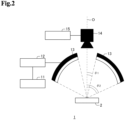
- Fig. 2 illustrates a modification of the image capturing system 1.
- the image capturing system 1 of the modification of Fig. 2 includes the measurement means 11, the control means 12, the illumination means 13, the capturing means 14, and a collation means 15.
- the functions of the measurement means 11, the control means 12, and the illumination means 13 are the same as those of the example of Fig. 1 described above.
- the capturing means 14 in the modification transmits captured image data to the collation means 15.
- the collation means 15 uses the image data acquired from the capturing means 14 to perform identification, collection, and authenticity determination of an object. For example, the collation means 15 performs an identification and collation process of an object using information extracted from the acquired image data and information previously stored in a storage means such as a database. For example, the collation means 15 compares the feature amount of an image obtained from the received image data with the previously stored feature amount. As a result of comparison, when the feature amounts of the two match, the collation means 15 may determine that the collation target object and the object corresponding to the stored feature amount are identical.
- the feature amount to be used for collation may be a feature point that is a characteristic point existing at an edge or a corner extracted from the image data.
- the feature amount may be a local feature amount that is a feature amount related to a feature point extracted from the image data.
- the local feature amount can be extracted from the feature point extracted from the image data and a pixel value of a nearby pixel.
- the collation means 15 transmits a collection result to an external output means or a display means.
- a result of collation may be information or a message representing whether or not collation has succeeded.
- a result of collation may be information, a message (product No., manufacturing No., brand name, serial No., name of manufacturer, name of distribution dealer) or the like that can uniquely specify the identified individual.
- the external output means is, for example, a mobile terminal (smartphone, tablet, personal computer, mobile telephone, other terminals having a communication function and a display function) of a user to be collated, or a server used for providing services, and a collation result may be transmitted to a mobile terminal or a server.
- a user can check a collation result by the website or an application for providing collation service.
- the present invention is applicable to an object identifying device 10 having the image capturing system 1 (image capturing device) and the collation means 15 for performing a predetermined collation process based on the image captured by the image capturing system 1.
- the collation process described above is an example.
- the collation means 15 may perform a collation process using a method other than that illustrated above as an example.
- the function as the collation means 15 may be held by the control means 12, for example. That is, the object identifying device 10 may have one information processing device having a function as the control means 12 and a function as the collation means 15, instead of the control means 12 and the collation means 15.
- the exemplary configuration of the image capturing system 1 is as described above.
- a specific configuration of the object 2 is not particularly limited.
- Fig. 3 illustrates exemplary function blocks of the control means 12 in the present embodiment.
- the control means 12 includes a transmission/reception means 121, an inclination statistic value calculation means 122, an irradiation angle range determination means 123 (determination means), and an illumination control means 124.
- the control means 12 may include, for example, a storage device and an arithmetic unit such as a central processing unit (CPU) not illustrated.
- the control means 12 implements the respective processing means described above by the execution of a program stored in the storage device by the arithmetic unit.
- the transmission/reception means 121 transmits and receives information to and from the measurement means 11 and the illumination means 13.
- the transmission/reception means 121 receives unevenness measurement data that is a measurement result of unevenness on a surface of the object 2, from the measurement means 11.
- the inclination statistic value calculation means 122 calculates an inclination statistic value that is a statistic value of inclination distribution of unevenness on a surface of the object 2, on the basis of unevenness measurement data acquired from the transmission/reception means 121.
- the inclination statistic value calculation means 122 analyzes the unevenness measurement data to thereby calculate two types of inclination statistic values that are values corresponding to the inclination distribution of fine unevenness existing on the surface of the object 2.
- a first inclination statistic value ⁇ 1 that substantially halves the inclination distribution into two parts and a second inclination statistic value ⁇ 2 that represents a right bottom portion of the inclination distribution are calculated.
- ⁇ 1 may be a mean value and ⁇ 2 may be a 95% point.
- ⁇ 2 may be a 95% point.
- the inclination statistic values are not limited to them.
- arbitrary statistic values may be used such as ⁇ 1 being an average value and ⁇ 2 being an average value + 2 ⁇ ( ⁇ is a standard deviation).
- the irradiation angle range determination means 123 determines the irradiation angle range when the illumination means 13 irradiates the object 2, on the basis of the inclination statistic values calculated by the inclination statistic value calculation means 122. For example, the irradiation angle range determination means 123 calculates values of plane half angles ⁇ 1 and ⁇ 2 (see Fig. 1 ) of the irradiation solid angle with the vertical direction of the object 2 being the center, on the basis of the inclination statistic values. The irradiation angle range determination means 123 determines the irradiation angle range ( ⁇ 1, ⁇ 2) from the calculated plane half angles ⁇ 1 and ⁇ 2. Note that the plane half angles ⁇ 1 and ⁇ 2 of the irradiation solid angle show zenith angles from the optical axis O as illustrated in Fig. 1 .
- the irradiation angle range determination means 123 determines the irradiation angle range ( ⁇ 1, ⁇ 2) on the basis of the expression provided below to thereby enable image capturing in which the light-dark pattern is clear and the diffuse reflection is reduced.
- ⁇ 1 2 ⁇ ⁇ 1
- ⁇ 2 2 ⁇ ⁇ 2
- the irradiation angle range determination means 123 may calculate values that are almost twice as large as the inclination statistic values ⁇ 1 and ⁇ 2 that are calculation results by the inclination statistic value calculation means 122, as described above for example.
- the inclination statistic value calculation means 122 may determine the irradiation angle range ( ⁇ 1, ⁇ 2) from ⁇ 1 and ⁇ 2 that are twice as large as the statistic values ⁇ 1 and ⁇ 2.
- Fig. 4 is a schematic diagram of a part of unevenness on a surface of the object 2.
- an angle ⁇ is an inclination angle from the optical axis O of the normal line stood at a point P on the surface of an object.
- an image of the object 2 captured by the capturing means 14 has a light-dark pattern in which a portion of the object 2 having an inclination angle ⁇ of ⁇ 1 to ⁇ 2 is light.
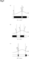
- Fig. 5 is a schematic diagram representing a change in a captured image with respect to a change in ⁇ 1 of the irradiation angle range ( ⁇ 1, ⁇ 2). More specifically, Fig. 5(a) illustrates one line portion (one-dimensional image 31) of the captured image, and a cross-section 32 of the surface of the object, where ⁇ 1 of the irradiation angle range ( ⁇ 1, ⁇ 2) satisfies ⁇ 1 ⁇ 2 ⁇ 1.
- Fig. 5(c) illustrates one line portion (one-dimensional image 31) of the captured image, and the cross-section 32 of the surface of the object, where ⁇ 1 satisfies ⁇ 1 > 2 ⁇ 1.
- Fig. 6 illustrates an example of inclination distribution of unevenness on the surface of the object 2.
- the first inclination statistic value ⁇ 1 substantially halves the area of the inclination distribution illustrated in Fig. 5 .
- the irradiation angle range determination means 123 calculates, for example, values that are almost twice as large as the inclination statistic values ⁇ 1 and ⁇ 2 that are calculation results by the inclination statistic value calculation means 122.
- the irradiation angle range determination means 123 determines the irradiation angle range ( ⁇ 1, ⁇ 2) from the calculated inclination statistic values.
- the illumination control means 124 controls the illumination means 13 and the like such that the irradiation angle range when the illumination means 13 irradiates the object 2 with light becomes ( ⁇ 1, ⁇ 2).
- the illumination control means 124 controls the lighting range of the illumination means 13 and the shielding range by the shielding means 131 formed in the illumination means 13 to allow the direct light to enter the object 2 by the illumination means 13 from the range in which the plane half angle ⁇ of the irradiation solid angle is between ⁇ 1 degrees to ⁇ 2 degrees.
- Fig. 7 illustrates an example of controlling the lighting range of the illumination means 13.
- the illumination means 13 is a multistage ring-type lighting in which each stage is dimmable independently.
- Fig. 7(a) illustrates an example of a lighting range of the illumination means 13 and the irradiation angle range ( ⁇ 1, ⁇ 2)
- Fig. 7(b) illustrates an example of the irradiation angle range ( ⁇ 1, ⁇ 2) when the lighting range of the illumination means 13 becomes narrower than that of the case illustrated in Fig. 7(a) .
- the values of the irradiation angle range ( ⁇ 1, ⁇ 2) can be controlled.
- Fig. 8 illustrates an example of controlling the shielding range of the shielding means 131 formed in the illumination means 13.
- the illumination means 13 is a dome-type lighting.
- the shielding means 131 is a diaphragm formed at the bottom of the lighting.
- Fig. 8(a) illustrates an example of the shielding range of the shielding means 131 and the irradiation angle range ( ⁇ 1, ⁇ 2).
- Fig. 8(b) illustrates an example of a configuration in which a range larger than that of the configuration of Fig. 8(a) is shielded (for example, narrowing the diaphragm).
- the illumination means 13 can narrow the irradiation angle range ( ⁇ 1, ⁇ 2).
- the method of controlling the shielding means 131 the values of the irradiation angle range ( ⁇ 1, ⁇ 2) can also be controlled.
- the illumination control means 124 controls the irradiation angle range ( ⁇ 1, ⁇ 2) by using any of the aforementioned means, a combination of the aforementioned means, a well-known means other than those described above, or a combination thereof. Note that the illumination control means 124 may control the irradiation angle range ( ⁇ 1, ⁇ 2) by using a method other than those illustrated above.
- control means 12 The exemplary configuration of the control means 12 is as described above. Note that the configuration of the control means 12 is not limited to that described above.
- the function as the inclination statistic value calculation means 122 held by the control means 12 may be held by the measurement means 11. That is, the control means 12 may be configured to receive the inclination statistic value calculated by the measurement means 11. In that case, the control means 12 may not have the inclination statistic value calculation means 122.
- the function as the illumination control means 124 held by the control means 12 may be held by the illumination means 13. That is, the control means 12 may be configured to transmit the irradiation angle range determined by the irradiation angle range determination means 123 to the illumination means 13. In that case, the control means 12 may not have the illumination control means 124.
- control means 12 may be configured to transmit the irradiation angle range determined by the irradiation angle range determination means 123 to a screen display unit such as a liquid crystal display (LCD) not illustrated or an external information processing device.
- control of the illumination means 13 may be performed manually by an operator or the like, for example.
- control means 12 may be configured to determine an irradiation angle range with respect to the object 2 by the illumination means 13 on the basis of the inclination statistic value received from the measurement means 11, and transmit the determined irradiation angle range to the illumination means 13.
- the measurement means 11 measures unevenness on a surface of the object 2 and acquires unevenness measurement data (step S101).
- the measurement means 11 transmits the acquired unevenness measurement data to the control means 12 (step S102).
- the inclination statistic value calculation means 122 of the control means 12 calculates the first inclination statistic value ⁇ 1 and the second inclination statistic value ⁇ 2 that are statistic values of inclination distribution, from the unevenness measurement data (step S201).
- the irradiation angle range determination means 123 determines the irradiation angle range ( ⁇ 1, ⁇ 2) on the basis of the inclination statistic values calculated by the inclination statistic value calculation means 122 (step S202). For example, the irradiation angle range determination means 123 calculates a value that is almost twice as large as the first inclination statistic value ⁇ 1 as ⁇ 1, and a value that is almost twice as large as the second inclination statistic value ⁇ 2 as ⁇ 2.
- the illumination control means 124 controls the illumination means 13 on the basis of the irradiation angle determined by the irradiation angle range determination means 123 (step S203). For example, the illumination control means 124 controls the distance between the illumination means 13 and the object 2 and the shielding range by the shielding means 131 formed in the illumination means 13 to allow the direct light to enter the object 2 by the illumination means 13 from the range in which the zenith angle is between ⁇ 1 degrees to ⁇ 2 degrees.
- the illumination control means 124 can be configured to notify the capturing means 14 of the fact that illumination control has been completed. Notification to the capturing means 14 may be performed by the illumination means 13.
- the capturing means 14 After completion of control by the illumination control means 124, at the timing of irradiating the object 2 by the illumination means 13, the capturing means 14 captures an image (step S301). Note that capturing of an image by the capturing means 14 may be performed manually.
- step S201 may be performed by the measurement means 11. Further, the process of step S203 may be performed by the illumination means 13.
- the image capturing system 1 of the present embodiment includes the measurement means 11 and the control means 12. Further, the control means 12 includes the inclination statistic value calculation means 122 and the irradiation angle range determination means 123.
- the inclination statistic value calculation means 122 can calculate the inclination statistic values on the basis of the measurement result by the measurement means 11.
- the irradiation angle range determination means 123 can determine the irradiation angle when the illumination means 13 irradiates the object 2, on the basis of the inclination statistic values calculated by the inclination statistic value calculation means 122.
- a high-contrast image can be acquired. That is, with the configuration described above, it is possible to acquire a high-contrast image easily.
- Fig. 10 illustrates an example of a captured image of a surface of the actual object 2 performed by using the image capturing system 1, in order to show an effect of adjusting ⁇ 1 to make areas of light and dark almost half and half.
- Fig. 10(b) is an example of a captured image when ⁇ 1 ⁇ 2 ⁇ 1.
- Fig. 11 illustrates an example of a captured image of a surface of the actual object 2 performed by using the image capturing system 1, in order to show an effect of reducing the diffuse reflection on the surface of the object 2.
- Fig. 1 1(b) is an example of a captured image when ⁇ 2 > 2 ⁇ 2.
- the irradiation angle range can be determined by using measurement data of unevenness on a surface of the object. Accordingly, it is possible to select and adjust a lighting device before capturing an image of an object. Therefore, it is possible to reduce the cost before introduction.
- the information processing device 40 is a device to be used in an image capturing device that illuminates an object by an illumination means and captures reflected light from the object as a reflection image by a capturing means.
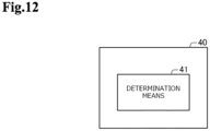
- Fig. 12 illustrates an exemplary configuration of the information processing device 40. Referring to Fig. 12 , the information processing device 40 includes a determination means 41.
- the information processing device 40 implements the determination means 41 by execution of a program stored in a storage device by an arithmetic unit such as a CPU.
- the determination means 71 determines the irradiation angle range for irradiating an object by the illumination means, on the basis of two types of inclination statistic values that are values corresponding to the inclination distribution of the unevenness existing on the surface of the object.
- the information processing device 40 includes the determination means 71.
- the determination means 71 is able to determine an irradiation angle range for irradiating an object by the illumination means, on the basis of two types of inclination statistic values that are values corresponding to the inclination distribution of unevenness existing on a surface of the object.
- the determination means 71 determines an irradiation angle range for irradiating an object by the illumination means, on the basis of two types of inclination statistic values that are values corresponding to the inclination distribution of unevenness existing on a surface of the object.
- a program that is another aspect of the present invention is a program for, in an information processing device to be used in an image capturing device that irradiates an object by an illumination means and captures reflected light from the object as a reflection image by a capturing means, realizing a determination means for determining an irradiation angle range for irradiating the object by the illumination means, on the basis of two types of inclination statistic values that are values corresponding to the inclination distribution of unevenness existing on a surface of the object.
- an information processing method to be executed by the information processing device 40 is an information processing method to be executed by an information processing device used in an image capturing device that irradiates an object by an illumination means and captures reflected light from the object as a reflection image by a capturing means.
- the method includes determining an irradiation angle range for irradiating an object by an illumination means on the basis of two types of inclination statistic values that are values corresponding to the inclination distribution of unevenness existing on a surface of an object.
- An invention of a program (or a computer-readable storage medium storing a program) or an information processing method having the above-described configuration also exhibits the same actions and effects as those of the information processing device 40. Therefore, the above-described object of the present invention can also be achieved by such an invention. Moreover, by an information processing system including the information processing device 40, an illumination means, and a capturing means, the object of the present invention can also be achieved as in the case of the information processing device 40.
- the program described in the exemplary embodiments may be stored in a storage device or stored on a storage medium readable by a computer.
- the storage medium is a portable medium such as a flexible disk, an optical disk, a magneto-optical disk, or a semiconductor memory, for example.
Landscapes
- Engineering & Computer Science (AREA)
- Multimedia (AREA)
- Physics & Mathematics (AREA)
- General Physics & Mathematics (AREA)
- Theoretical Computer Science (AREA)
- Signal Processing (AREA)
- Computer Vision & Pattern Recognition (AREA)
- Quality & Reliability (AREA)
- Human Computer Interaction (AREA)
- Image Input (AREA)
- Length Measuring Devices By Optical Means (AREA)
- Investigating Materials By The Use Of Optical Means Adapted For Particular Applications (AREA)
- Investigating Or Analysing Materials By Optical Means (AREA)
Claims (4)
- Bilderfassungsvorrichtung, umfassend:eine Messeinrichtung (11) zum Erzeugen eines Messergebnisses einer auf einer Oberfläche eines Objekts existierenden Unebenheit;eine Berechnungseinrichtung (122) zum Erzeugen einer Neigungsverteilung, die eine Beziehung zwischen Neigungswinkeln bei einer Anzahl von Punkten auf der Oberfläche des Subjekts und ihren Frequenzen darstellt, auf einer Basis des Messergebnisses, und Berechnen eines ersten Neigungsstatistikwerts, der ein Neigungswinkel ist, der ein Gebiet der Neigungsverteilung in zwei Teile halbiert, und eines zweiten Neigungsstatistikwerts, der ein Neigungswinkel ist, der einen rechten Ausläufer der Neigungsverteilung darstellt;eine Bestimmungseinrichtung (123) zum Bestimmen eines Bestrahlungswinkelbereichs zum Bestrahlen des Objekts durch eine Belichtungseinrichtung (13) auf einer Basis des ersten Neigungsstatistikwerts und des zweiten Neigungsstatistikwerts, die durch die Berechnungseinrichtung (122) berechnet sind;wobei die Belichtungseinrichtung (13) zum Bestrahlen des Objekts mit dem bestimmten Bestrahlungswinkelbereich konfiguriert ist; undeine Erfassungseinrichtung (14) zum Erfassen von reflektiertem Licht vom Objekt, das durch die Belichtungseinrichtung (13) mit dem bestimmten Bestrahlungswinkelbereich bestrahlt wird, als Reflexionsbild,wobei die Belichtungseinrichtung und die Erfassungseinrichtung derart angeordnet sind, dass sie eine gemeinsame optische Achse direkt über dem Objekt in der vertikalen Richtung haben;wobei die Belichtungseinrichtung eine ringartige oder kuppelartige Form hat; undwobei der Neigungswinkel bei einem Punkt auf der Oberfläche des Objekts ein Winkel ist, der zwischen einer normalen Linie bei dem Punkt und einer Linie bei dem Punkt, die parallel zu einer optischen Achse der Belichtungseinrichtung (13) und einer optischen Achse der Erfassungseinrichtung (14) ausgebildet ist.
- Bilderfassungsvorrichtung nach Anspruch 1, weiterhin umfassend:
eine Steuereinrichtung (124) zum derartigen Steuern der Belichtungseinrichtung (13), dass sie den durch die Bestimmungseinrichtung (123) bestimmten Bestrahlungswinkelbereich realisiert. - Informationsverarbeitungsverfahren, umfassend:Erzeugen eines Messergebnisses einer auf einer Oberfläche eines Objekts existierenden Unebenheit;Erzeugen einer Neigungsverteilung, die eine Beziehung zwischen Neigungswinkeln bei einer Anzahl von Punkten auf der Oberfläche des Subjekts und ihren Frequenzen darstellt, auf einer Basis des Messergebnisses;Berechnen eines ersten Neigungsstatistikwerts, der ein Neigungswinkel ist, der ein Gebiet der Neigungsverteilung in zwei Teile halbiert, und eines zweiten Neigungsstatistikwerts, der ein Neigungswinkel ist, der einen rechten Ausläufer der Neigungsverteilung darstellt;Bestimmen eines Bestrahlungswinkelbereichs zum Bestrahlen des Objekts durch eine Belichtungseinrichtung (13) auf einer Basis des ersten Neigungsstatistikwerts und des zweiten Neigungsstatistikwerts;Steuern der Belichtungseinrichtung (13), um das Objekt mit dem bestimmten Bestrahlungswinkelbereich zu belichten; undeiner Erfassungseinrichtung (14), die reflektiertes Licht vom Objekt, das durch die Belichtungseinrichtung (13) mit dem bestimmten Bestrahlungswinkelbereich bestrahlt wird, als Reflexionsbild erfasst,wobei die Belichtungseinrichtung und die Erfassungseinrichtung derart angeordnet sind, dass sie eine gemeinsame optische Achse direkt über dem Objekt in der vertikalen Richtung haben;wobei die Belichtungseinrichtung eine ringartige oder kuppelartige Form hat; undwobei der Neigungswinkel bei einem Punkt auf der Oberfläche des Objekts ein zwischen einer normalen Linie bei dem Punkt und einer Linie bei dem Punkt, die parallel zu einer optischen Achse der Belichtungseinrichtung (13) und einer optischen Achse der Erfassungseinrichtung (14) ist, ausgebildeter Winkel ist.
- Programm, das Anweisungen zum Veranlassen, dass eine Bilderfassungsvorrichtung nach Anspruch 1 das Verfahren nach Anspruch ausführt, enthält.
Applications Claiming Priority (1)
| Application Number | Priority Date | Filing Date | Title |
|---|---|---|---|
| PCT/JP2019/005640 WO2020166075A1 (ja) | 2019-02-15 | 2019-02-15 | 情報処理装置 |
Publications (3)
| Publication Number | Publication Date |
|---|---|
| EP3926575A1 EP3926575A1 (de) | 2021-12-22 |
| EP3926575A4 EP3926575A4 (de) | 2022-03-02 |
| EP3926575B1 true EP3926575B1 (de) | 2024-06-05 |
Family
ID=72044436
Family Applications (1)
| Application Number | Title | Priority Date | Filing Date |
|---|---|---|---|
| EP19914778.6A Active EP3926575B1 (de) | 2019-02-15 | 2019-02-15 | Informationsverarbeitungsvorrichtung, verfahren und programm |
Country Status (4)
| Country | Link |
|---|---|
| US (1) | US11941849B2 (de) |
| EP (1) | EP3926575B1 (de) |
| JP (1) | JP7251559B2 (de) |
| WO (1) | WO2020166075A1 (de) |
Families Citing this family (2)
| Publication number | Priority date | Publication date | Assignee | Title |
|---|---|---|---|---|
| JP2022127535A (ja) * | 2021-02-19 | 2022-08-31 | 株式会社キーエンス | 拡大観察装置、拡大画像観察方法、拡大画像観察プログラム及びコンピュータで読み取り可能な記録媒体並びに記憶した機器 |
| CN114295558B (zh) * | 2021-12-31 | 2023-08-22 | 四川启睿克科技有限公司 | 便携式光谱仪 |
Citations (1)
| Publication number | Priority date | Publication date | Assignee | Title |
|---|---|---|---|---|
| WO2017080975A1 (en) * | 2015-11-10 | 2017-05-18 | Alpvision S.A. | Method and apparatus for authentication of a 3d structure |
Family Cites Families (10)
| Publication number | Priority date | Publication date | Assignee | Title |
|---|---|---|---|---|
| JP3204234B2 (ja) * | 1998-12-15 | 2001-09-04 | 日本電気株式会社 | 凹凸情報を強調する装置及び凹凸情報を強調する方法 |
| JP2008202949A (ja) | 2007-02-16 | 2008-09-04 | Omron Corp | 欠陥検査方法および欠陥検査装置 |
| JP5014003B2 (ja) * | 2007-07-12 | 2012-08-29 | キヤノン株式会社 | 検査装置および方法 |
| BRPI0917910B1 (pt) * | 2008-08-26 | 2019-08-20 | Kabushiki Kaisha Bridgestone | Método e aparelho para detectar desigualdade de superfície de um objeto sob inspeção |
| JP5144461B2 (ja) * | 2008-10-17 | 2013-02-13 | 株式会社日立製作所 | 指静脈認証装置、及び個人認証装置 |
| JP5921330B2 (ja) * | 2012-05-17 | 2016-05-24 | 礼治 大島 | 画像処理方法 |
| WO2014021449A1 (ja) * | 2012-08-03 | 2014-02-06 | 日本電気株式会社 | 撮影補助具、撮影装置及び撮影方法 |
| WO2014163014A1 (ja) | 2013-04-04 | 2014-10-09 | 日本電気株式会社 | 識別システム、識別方法、照合装置及びプログラム |
| JP5866586B1 (ja) | 2015-09-22 | 2016-02-17 | マシンビジョンライティング株式会社 | 検査用照明装置及び検査システム |
| US11423632B2 (en) * | 2017-10-24 | 2022-08-23 | Nec Corporation | Device and method for determining surface irregularities with irradiation angle |
-
2019
- 2019-02-15 EP EP19914778.6A patent/EP3926575B1/de active Active
- 2019-02-15 US US17/430,533 patent/US11941849B2/en active Active
- 2019-02-15 JP JP2020572049A patent/JP7251559B2/ja active Active
- 2019-02-15 WO PCT/JP2019/005640 patent/WO2020166075A1/ja not_active Ceased
Patent Citations (1)
| Publication number | Priority date | Publication date | Assignee | Title |
|---|---|---|---|---|
| WO2017080975A1 (en) * | 2015-11-10 | 2017-05-18 | Alpvision S.A. | Method and apparatus for authentication of a 3d structure |
Also Published As
| Publication number | Publication date |
|---|---|
| JPWO2020166075A1 (ja) | 2021-12-02 |
| WO2020166075A1 (ja) | 2020-08-20 |
| JP7251559B2 (ja) | 2023-04-04 |
| US20220130072A1 (en) | 2022-04-28 |
| EP3926575A1 (de) | 2021-12-22 |
| EP3926575A4 (de) | 2022-03-02 |
| US11941849B2 (en) | 2024-03-26 |
Similar Documents
| Publication | Publication Date | Title |
|---|---|---|
| JP6629455B2 (ja) | 外観検査装置、照明装置、撮影照明装置 | |
| CN110691966B (zh) | 检查系统以及检查方式 | |
| JP5866573B1 (ja) | 検査用照明装置及び検査システム | |
| CN113632211A (zh) | 检查装置及检查方法 | |
| US11423632B2 (en) | Device and method for determining surface irregularities with irradiation angle | |
| US20230243758A1 (en) | Tilt and focusing adjustment for consistent gem imaging | |
| EP3926575B1 (de) | Informationsverarbeitungsvorrichtung, verfahren und programm | |
| KR101892099B1 (ko) | 기판 상에 형성된 부품의 터미널 검사방법 및 기판 검사장치 | |
| TWI834843B (zh) | 檢查裝置及檢查方法 | |
| US11729512B2 (en) | Image capturing device captures an object in an illumination environment appropriate for individual identification and object collation | |
| TW201629474A (zh) | 檢查裝置 | |
| CN112051037B (zh) | 镜片检测方法、装置及终端设备 | |
| KR101227110B1 (ko) | 검사 장치의 진단 및 측정변수 설정 방법 | |
| US10444162B2 (en) | Method of testing an object and apparatus for performing the same | |
| JP5475167B1 (ja) | ワーク検出装置及びワーク検出方法 | |
| JP2018124200A (ja) | 処理装置、処理方法、システム、および物品製造方法 | |
| JP2011220755A (ja) | 表面外観検査装置 | |
| JP2020177032A (ja) | 検査装置及び検査方法 | |
| CN114144661B (zh) | 检查测定用照明装置、检查测定系统以及检查测定方法 | |
| KR20180112655A (ko) | 검사장치 및 검사방법 | |
| KR101227116B1 (ko) | 검사 장치의 진단 및 측정변수 설정 방법 | |
| TW202300881A (zh) | 檢測方法、裝置及電腦可讀存儲介質 |
Legal Events
| Date | Code | Title | Description |
|---|---|---|---|
| STAA | Information on the status of an ep patent application or granted ep patent |
Free format text: STATUS: THE INTERNATIONAL PUBLICATION HAS BEEN MADE |
|
| TPAC | Observations filed by third parties |
Free format text: ORIGINAL CODE: EPIDOSNTIPA |
|
| PUAI | Public reference made under article 153(3) epc to a published international application that has entered the european phase |
Free format text: ORIGINAL CODE: 0009012 |
|
| STAA | Information on the status of an ep patent application or granted ep patent |
Free format text: STATUS: REQUEST FOR EXAMINATION WAS MADE |
|
| 17P | Request for examination filed |
Effective date: 20210813 |
|
| AK | Designated contracting states |
Kind code of ref document: A1 Designated state(s): AL AT BE BG CH CY CZ DE DK EE ES FI FR GB GR HR HU IE IS IT LI LT LU LV MC MK MT NL NO PL PT RO RS SE SI SK SM TR |
|
| A4 | Supplementary search report drawn up and despatched |
Effective date: 20220128 |
|
| RIC1 | Information provided on ipc code assigned before grant |
Ipc: H04N 5/225 20060101ALI20220124BHEP Ipc: G03F 7/20 20060101ALI20220124BHEP Ipc: G02B 21/06 20060101ALI20220124BHEP Ipc: G02B 21/00 20060101ALI20220124BHEP Ipc: G01N 21/88 20060101ALI20220124BHEP Ipc: G01B 11/30 20060101ALI20220124BHEP Ipc: G01B 11/24 20060101ALI20220124BHEP Ipc: G06T 1/00 20060101AFI20220124BHEP |
|
| DAV | Request for validation of the european patent (deleted) | ||
| DAX | Request for extension of the european patent (deleted) | ||
| RIC1 | Information provided on ipc code assigned before grant |
Ipc: G01B 11/24 20060101ALI20231117BHEP Ipc: G01B 11/30 20060101ALI20231117BHEP Ipc: G01N 21/88 20060101ALI20231117BHEP Ipc: G02B 21/00 20060101ALI20231117BHEP Ipc: G02B 21/06 20060101ALI20231117BHEP Ipc: G03F 7/20 20060101ALI20231117BHEP Ipc: G06T 1/00 20060101AFI20231117BHEP |
|
| GRAP | Despatch of communication of intention to grant a patent |
Free format text: ORIGINAL CODE: EPIDOSNIGR1 |
|
| STAA | Information on the status of an ep patent application or granted ep patent |
Free format text: STATUS: GRANT OF PATENT IS INTENDED |
|
| INTG | Intention to grant announced |
Effective date: 20240109 |
|
| GRAS | Grant fee paid |
Free format text: ORIGINAL CODE: EPIDOSNIGR3 |
|
| GRAA | (expected) grant |
Free format text: ORIGINAL CODE: 0009210 |
|
| STAA | Information on the status of an ep patent application or granted ep patent |
Free format text: STATUS: THE PATENT HAS BEEN GRANTED |
|
| AK | Designated contracting states |
Kind code of ref document: B1 Designated state(s): AL AT BE BG CH CY CZ DE DK EE ES FI FR GB GR HR HU IE IS IT LI LT LU LV MC MK MT NL NO PL PT RO RS SE SI SK SM TR |
|
| REG | Reference to a national code |
Ref country code: CH Ref legal event code: EP |
|
| REG | Reference to a national code |
Ref country code: DE Ref legal event code: R096 Ref document number: 602019053402 Country of ref document: DE |
|
| REG | Reference to a national code |
Ref country code: IE Ref legal event code: FG4D |
|
| REG | Reference to a national code |
Ref country code: LT Ref legal event code: MG9D |
|
| PG25 | Lapsed in a contracting state [announced via postgrant information from national office to epo] |
Ref country code: BG Free format text: LAPSE BECAUSE OF FAILURE TO SUBMIT A TRANSLATION OF THE DESCRIPTION OR TO PAY THE FEE WITHIN THE PRESCRIBED TIME-LIMIT Effective date: 20240605 |
|
| REG | Reference to a national code |
Ref country code: NL Ref legal event code: MP Effective date: 20240605 |
|
| PG25 | Lapsed in a contracting state [announced via postgrant information from national office to epo] |
Ref country code: FI Free format text: LAPSE BECAUSE OF FAILURE TO SUBMIT A TRANSLATION OF THE DESCRIPTION OR TO PAY THE FEE WITHIN THE PRESCRIBED TIME-LIMIT Effective date: 20240605 Ref country code: HR Free format text: LAPSE BECAUSE OF FAILURE TO SUBMIT A TRANSLATION OF THE DESCRIPTION OR TO PAY THE FEE WITHIN THE PRESCRIBED TIME-LIMIT Effective date: 20240605 |
|
| PG25 | Lapsed in a contracting state [announced via postgrant information from national office to epo] |
Ref country code: GR Free format text: LAPSE BECAUSE OF FAILURE TO SUBMIT A TRANSLATION OF THE DESCRIPTION OR TO PAY THE FEE WITHIN THE PRESCRIBED TIME-LIMIT Effective date: 20240906 |
|
| PG25 | Lapsed in a contracting state [announced via postgrant information from national office to epo] |
Ref country code: ES Free format text: LAPSE BECAUSE OF FAILURE TO SUBMIT A TRANSLATION OF THE DESCRIPTION OR TO PAY THE FEE WITHIN THE PRESCRIBED TIME-LIMIT Effective date: 20240605 |
|
| PG25 | Lapsed in a contracting state [announced via postgrant information from national office to epo] |
Ref country code: LV Free format text: LAPSE BECAUSE OF FAILURE TO SUBMIT A TRANSLATION OF THE DESCRIPTION OR TO PAY THE FEE WITHIN THE PRESCRIBED TIME-LIMIT Effective date: 20240605 |
|
| PG25 | Lapsed in a contracting state [announced via postgrant information from national office to epo] |
Ref country code: NO Free format text: LAPSE BECAUSE OF FAILURE TO SUBMIT A TRANSLATION OF THE DESCRIPTION OR TO PAY THE FEE WITHIN THE PRESCRIBED TIME-LIMIT Effective date: 20240905 Ref country code: LV Free format text: LAPSE BECAUSE OF FAILURE TO SUBMIT A TRANSLATION OF THE DESCRIPTION OR TO PAY THE FEE WITHIN THE PRESCRIBED TIME-LIMIT Effective date: 20240605 Ref country code: HR Free format text: LAPSE BECAUSE OF FAILURE TO SUBMIT A TRANSLATION OF THE DESCRIPTION OR TO PAY THE FEE WITHIN THE PRESCRIBED TIME-LIMIT Effective date: 20240605 Ref country code: GR Free format text: LAPSE BECAUSE OF FAILURE TO SUBMIT A TRANSLATION OF THE DESCRIPTION OR TO PAY THE FEE WITHIN THE PRESCRIBED TIME-LIMIT Effective date: 20240906 Ref country code: FI Free format text: LAPSE BECAUSE OF FAILURE TO SUBMIT A TRANSLATION OF THE DESCRIPTION OR TO PAY THE FEE WITHIN THE PRESCRIBED TIME-LIMIT Effective date: 20240605 Ref country code: ES Free format text: LAPSE BECAUSE OF FAILURE TO SUBMIT A TRANSLATION OF THE DESCRIPTION OR TO PAY THE FEE WITHIN THE PRESCRIBED TIME-LIMIT Effective date: 20240605 Ref country code: BG Free format text: LAPSE BECAUSE OF FAILURE TO SUBMIT A TRANSLATION OF THE DESCRIPTION OR TO PAY THE FEE WITHIN THE PRESCRIBED TIME-LIMIT Effective date: 20240605 Ref country code: RS Free format text: LAPSE BECAUSE OF FAILURE TO SUBMIT A TRANSLATION OF THE DESCRIPTION OR TO PAY THE FEE WITHIN THE PRESCRIBED TIME-LIMIT Effective date: 20240905 |
|
| PG25 | Lapsed in a contracting state [announced via postgrant information from national office to epo] |
Ref country code: NL Free format text: LAPSE BECAUSE OF FAILURE TO SUBMIT A TRANSLATION OF THE DESCRIPTION OR TO PAY THE FEE WITHIN THE PRESCRIBED TIME-LIMIT Effective date: 20240605 |
|
| REG | Reference to a national code |
Ref country code: AT Ref legal event code: MK05 Ref document number: 1693011 Country of ref document: AT Kind code of ref document: T Effective date: 20240605 |
|
| PG25 | Lapsed in a contracting state [announced via postgrant information from national office to epo] |
Ref country code: NL Free format text: LAPSE BECAUSE OF FAILURE TO SUBMIT A TRANSLATION OF THE DESCRIPTION OR TO PAY THE FEE WITHIN THE PRESCRIBED TIME-LIMIT Effective date: 20240605 |
|
| PG25 | Lapsed in a contracting state [announced via postgrant information from national office to epo] |
Ref country code: PT Free format text: LAPSE BECAUSE OF FAILURE TO SUBMIT A TRANSLATION OF THE DESCRIPTION OR TO PAY THE FEE WITHIN THE PRESCRIBED TIME-LIMIT Effective date: 20241007 |
|
| PG25 | Lapsed in a contracting state [announced via postgrant information from national office to epo] |
Ref country code: PT Free format text: LAPSE BECAUSE OF FAILURE TO SUBMIT A TRANSLATION OF THE DESCRIPTION OR TO PAY THE FEE WITHIN THE PRESCRIBED TIME-LIMIT Effective date: 20241007 |
|
| PG25 | Lapsed in a contracting state [announced via postgrant information from national office to epo] |
Ref country code: PL Free format text: LAPSE BECAUSE OF FAILURE TO SUBMIT A TRANSLATION OF THE DESCRIPTION OR TO PAY THE FEE WITHIN THE PRESCRIBED TIME-LIMIT Effective date: 20240605 |
|
| PG25 | Lapsed in a contracting state [announced via postgrant information from national office to epo] |
Ref country code: EE Free format text: LAPSE BECAUSE OF FAILURE TO SUBMIT A TRANSLATION OF THE DESCRIPTION OR TO PAY THE FEE WITHIN THE PRESCRIBED TIME-LIMIT Effective date: 20240605 |
|
| PG25 | Lapsed in a contracting state [announced via postgrant information from national office to epo] |
Ref country code: AT Free format text: LAPSE BECAUSE OF FAILURE TO SUBMIT A TRANSLATION OF THE DESCRIPTION OR TO PAY THE FEE WITHIN THE PRESCRIBED TIME-LIMIT Effective date: 20240605 Ref country code: IS Free format text: LAPSE BECAUSE OF FAILURE TO SUBMIT A TRANSLATION OF THE DESCRIPTION OR TO PAY THE FEE WITHIN THE PRESCRIBED TIME-LIMIT Effective date: 20241005 |
|
| PG25 | Lapsed in a contracting state [announced via postgrant information from national office to epo] |
Ref country code: CZ Free format text: LAPSE BECAUSE OF FAILURE TO SUBMIT A TRANSLATION OF THE DESCRIPTION OR TO PAY THE FEE WITHIN THE PRESCRIBED TIME-LIMIT Effective date: 20240605 |
|
| PG25 | Lapsed in a contracting state [announced via postgrant information from national office to epo] |
Ref country code: RO Free format text: LAPSE BECAUSE OF FAILURE TO SUBMIT A TRANSLATION OF THE DESCRIPTION OR TO PAY THE FEE WITHIN THE PRESCRIBED TIME-LIMIT Effective date: 20240605 Ref country code: SK Free format text: LAPSE BECAUSE OF FAILURE TO SUBMIT A TRANSLATION OF THE DESCRIPTION OR TO PAY THE FEE WITHIN THE PRESCRIBED TIME-LIMIT Effective date: 20240605 |
|
| PG25 | Lapsed in a contracting state [announced via postgrant information from national office to epo] |
Ref country code: SM Free format text: LAPSE BECAUSE OF FAILURE TO SUBMIT A TRANSLATION OF THE DESCRIPTION OR TO PAY THE FEE WITHIN THE PRESCRIBED TIME-LIMIT Effective date: 20240605 |
|
| PG25 | Lapsed in a contracting state [announced via postgrant information from national office to epo] |
Ref country code: SM Free format text: LAPSE BECAUSE OF FAILURE TO SUBMIT A TRANSLATION OF THE DESCRIPTION OR TO PAY THE FEE WITHIN THE PRESCRIBED TIME-LIMIT Effective date: 20240605 Ref country code: SK Free format text: LAPSE BECAUSE OF FAILURE TO SUBMIT A TRANSLATION OF THE DESCRIPTION OR TO PAY THE FEE WITHIN THE PRESCRIBED TIME-LIMIT Effective date: 20240605 Ref country code: RO Free format text: LAPSE BECAUSE OF FAILURE TO SUBMIT A TRANSLATION OF THE DESCRIPTION OR TO PAY THE FEE WITHIN THE PRESCRIBED TIME-LIMIT Effective date: 20240605 Ref country code: PL Free format text: LAPSE BECAUSE OF FAILURE TO SUBMIT A TRANSLATION OF THE DESCRIPTION OR TO PAY THE FEE WITHIN THE PRESCRIBED TIME-LIMIT Effective date: 20240605 Ref country code: IS Free format text: LAPSE BECAUSE OF FAILURE TO SUBMIT A TRANSLATION OF THE DESCRIPTION OR TO PAY THE FEE WITHIN THE PRESCRIBED TIME-LIMIT Effective date: 20241005 Ref country code: EE Free format text: LAPSE BECAUSE OF FAILURE TO SUBMIT A TRANSLATION OF THE DESCRIPTION OR TO PAY THE FEE WITHIN THE PRESCRIBED TIME-LIMIT Effective date: 20240605 Ref country code: CZ Free format text: LAPSE BECAUSE OF FAILURE TO SUBMIT A TRANSLATION OF THE DESCRIPTION OR TO PAY THE FEE WITHIN THE PRESCRIBED TIME-LIMIT Effective date: 20240605 Ref country code: AT Free format text: LAPSE BECAUSE OF FAILURE TO SUBMIT A TRANSLATION OF THE DESCRIPTION OR TO PAY THE FEE WITHIN THE PRESCRIBED TIME-LIMIT Effective date: 20240605 |
|
| PG25 | Lapsed in a contracting state [announced via postgrant information from national office to epo] |
Ref country code: IT Free format text: LAPSE BECAUSE OF FAILURE TO SUBMIT A TRANSLATION OF THE DESCRIPTION OR TO PAY THE FEE WITHIN THE PRESCRIBED TIME-LIMIT Effective date: 20240605 |
|
| REG | Reference to a national code |
Ref country code: DE Ref legal event code: R097 Ref document number: 602019053402 Country of ref document: DE |
|
| PLBE | No opposition filed within time limit |
Free format text: ORIGINAL CODE: 0009261 |
|
| STAA | Information on the status of an ep patent application or granted ep patent |
Free format text: STATUS: NO OPPOSITION FILED WITHIN TIME LIMIT |
|
| PG25 | Lapsed in a contracting state [announced via postgrant information from national office to epo] |
Ref country code: DK Free format text: LAPSE BECAUSE OF FAILURE TO SUBMIT A TRANSLATION OF THE DESCRIPTION OR TO PAY THE FEE WITHIN THE PRESCRIBED TIME-LIMIT Effective date: 20240605 |
|
| 26N | No opposition filed |
Effective date: 20250306 |
|
| PG25 | Lapsed in a contracting state [announced via postgrant information from national office to epo] |
Ref country code: SE Free format text: LAPSE BECAUSE OF FAILURE TO SUBMIT A TRANSLATION OF THE DESCRIPTION OR TO PAY THE FEE WITHIN THE PRESCRIBED TIME-LIMIT Effective date: 20240605 |
|
| PG25 | Lapsed in a contracting state [announced via postgrant information from national office to epo] |
Ref country code: MC Free format text: LAPSE BECAUSE OF FAILURE TO SUBMIT A TRANSLATION OF THE DESCRIPTION OR TO PAY THE FEE WITHIN THE PRESCRIBED TIME-LIMIT Effective date: 20240605 |
|
| REG | Reference to a national code |
Ref country code: CH Ref legal event code: PL |
|
| PG25 | Lapsed in a contracting state [announced via postgrant information from national office to epo] |
Ref country code: LU Free format text: LAPSE BECAUSE OF NON-PAYMENT OF DUE FEES Effective date: 20250215 |
|
| PG25 | Lapsed in a contracting state [announced via postgrant information from national office to epo] |
Ref country code: CH Free format text: LAPSE BECAUSE OF NON-PAYMENT OF DUE FEES Effective date: 20250228 |
|
| GBPC | Gb: european patent ceased through non-payment of renewal fee |
Effective date: 20250215 |
|
| REG | Reference to a national code |
Ref country code: BE Ref legal event code: MM Effective date: 20250228 |
|
| PG25 | Lapsed in a contracting state [announced via postgrant information from national office to epo] |
Ref country code: GB Free format text: LAPSE BECAUSE OF NON-PAYMENT OF DUE FEES Effective date: 20250215 |
|
| PG25 | Lapsed in a contracting state [announced via postgrant information from national office to epo] |
Ref country code: FR Free format text: LAPSE BECAUSE OF NON-PAYMENT OF DUE FEES Effective date: 20250228 |
|
| PG25 | Lapsed in a contracting state [announced via postgrant information from national office to epo] |
Ref country code: BE Free format text: LAPSE BECAUSE OF NON-PAYMENT OF DUE FEES Effective date: 20250228 |
|
| PG25 | Lapsed in a contracting state [announced via postgrant information from national office to epo] |
Ref country code: IE Free format text: LAPSE BECAUSE OF NON-PAYMENT OF DUE FEES Effective date: 20250215 |
|
| PGFP | Annual fee paid to national office [announced via postgrant information from national office to epo] |
Ref country code: DE Payment date: 20260218 Year of fee payment: 8 |