EP3926607A1 - Procédés, systèmes et appareils permettant d'identifier et d'indiquer les procédures d'approche au point de visée de piste secondaire (srap) - Google Patents
Procédés, systèmes et appareils permettant d'identifier et d'indiquer les procédures d'approche au point de visée de piste secondaire (srap) Download PDFInfo
- Publication number
- EP3926607A1 EP3926607A1 EP21177508.5A EP21177508A EP3926607A1 EP 3926607 A1 EP3926607 A1 EP 3926607A1 EP 21177508 A EP21177508 A EP 21177508A EP 3926607 A1 EP3926607 A1 EP 3926607A1
- Authority
- EP
- European Patent Office
- Prior art keywords
- aircraft
- srap
- ownship
- paired
- approach
- Prior art date
- Legal status (The legal status is an assumption and is not a legal conclusion. Google has not performed a legal analysis and makes no representation as to the accuracy of the status listed.)
- Pending
Links
Images



Classifications
-
- G—PHYSICS
- G08—SIGNALLING
- G08G—TRAFFIC CONTROL SYSTEMS
- G08G5/00—Traffic control systems for aircraft
- G08G5/20—Arrangements for acquiring, generating, sharing or displaying traffic information
- G08G5/21—Arrangements for acquiring, generating, sharing or displaying traffic information located onboard the aircraft
-
- G—PHYSICS
- G08—SIGNALLING
- G08G—TRAFFIC CONTROL SYSTEMS
- G08G5/00—Traffic control systems for aircraft
- G08G5/20—Arrangements for acquiring, generating, sharing or displaying traffic information
- G08G5/26—Transmission of traffic-related information between aircraft and ground stations
-
- G—PHYSICS
- G08—SIGNALLING
- G08G—TRAFFIC CONTROL SYSTEMS
- G08G5/00—Traffic control systems for aircraft
- G08G5/50—Navigation or guidance aids
-
- G—PHYSICS
- G08—SIGNALLING
- G08G—TRAFFIC CONTROL SYSTEMS
- G08G5/00—Traffic control systems for aircraft
- G08G5/50—Navigation or guidance aids
- G08G5/54—Navigation or guidance aids for approach or landing
-
- G—PHYSICS
- G08—SIGNALLING
- G08G—TRAFFIC CONTROL SYSTEMS
- G08G5/00—Traffic control systems for aircraft
- G08G5/50—Navigation or guidance aids
- G08G5/55—Navigation or guidance aids for a single aircraft
-
- G—PHYSICS
- G08—SIGNALLING
- G08G—TRAFFIC CONTROL SYSTEMS
- G08G5/00—Traffic control systems for aircraft
- G08G5/70—Arrangements for monitoring traffic-related situations or conditions
- G08G5/72—Arrangements for monitoring traffic-related situations or conditions for monitoring traffic
- G08G5/723—Arrangements for monitoring traffic-related situations or conditions for monitoring traffic from the aircraft
-
- G—PHYSICS
- G08—SIGNALLING
- G08G—TRAFFIC CONTROL SYSTEMS
- G08G5/00—Traffic control systems for aircraft
- G08G5/20—Arrangements for acquiring, generating, sharing or displaying traffic information
- G08G5/25—Transmission of traffic-related information between aircraft
Definitions
- the subject matter described herein generally relates to vehicle systems, and more particularly, embodiments of the subject matter are related to aircraft systems for enabling secondary runway aiming point (SRAP) approach procedures.
- SRAP secondary runway aiming point
- EUROCONTROL European Organization for the Safety of Air Navigation
- SRAP Secondary Runway Aiming Point
- SRAP secondary runway aiming point
- One exemplary method provides a Secondary Runway Aiming Point (SRAP) procedure of an approach by an ownship to an airport.
- the method includes initiating, by a SRAP application hosted by a processor of the ownship, the SRAP procedure during an approach flight phase to the airport, wherein the processor is configured to perform the steps of: identifying at least one aircraft from a plurality of aircraft making approaches to the airport during the ownship's approach flight phase that satisfy a set of preconditions in order to pair an aircraft which has been identified to the ownship in the SRAP procedure; calculating a set of results based on lateral and vertical deviations of a paired SRAP aircraft to the ownship, and differential lateral and vertical rates of the paired SRAP aircraft to the ownship; deriving one or more points from the calculated set of results based on the lateral and vertical deviations, and differential rates to determine whether in a flight path of the ownship an occurrence of an intrusion occurs into a wake of the paired SRAP aircraft during the approach flight phase to the
- the method includes displaying, by the configured processor, on the cockpit display, a pair of vertical profiles displaying the flight path of the ownship and the paired SRAP aircraft together for monitoring an intrusion in the wake of the paired SRAP aircraft in the flight path of the ownership.
- the method further includes displaying, by the configured processor, on the cockpit display, distances between the ownship and the paired aircraft in the vertical profiles of the flight path of the ownship and the paired SRAP aircraft to visually monitor for an intrusion in the wake of the paired SRAP aircraft by the ownship.
- the method further includes generating, by the configured processor, a visual alert for the intrusion in the wake of the paired SRAP aircraft by the ownship during the approach flight phase to the airport.
- the method further includes generating, by the configured processor, the visual alert in advance of the wake intrusion by the ownship to enable corrective action by the ownship for the wake intrusion in the approach flight phase.
- the method includes generating, by the configured processor, the visual alert in advance with at least a two-minute period of remaining flight time by the ownship in the approach flight phase.
- the method further includes sending, by the configured processor, the graphic data to display the visual alert on a multi-function display (MFD) within the cockpit display.
- the method further includes receiving, by the configured processor, user input of a selection of the aircraft on the MFD amongst a display of a set of aircraft to pair with the ownship by the SRAP application.
- the method further includes in response to user input of the selection of the SRAP paired aircraft, displaying by the configured processor, information about the SRAP paired aircraft on a graphic user interface (GUI) within the MFD.
- GUI graphic user interface
- Another exemplary method provides a system to execute a Secondary Runway Aiming Point (SRAP) procedure for an approach by an ownship to an airport.
- the system includes a processor configured to initiate the SRAP procedure by executing a SRAP application hosted by the processer of the ownship during an approach flight phase to the airport; the processor is configured to identify by executing the SRAP application at least one aircraft from a plurality of aircraft making approaches to the airport during the ownship's approach flight phase that satisfy a set of preconditions in order to pair an aircraft which has been identified to the ownship in the SRAP procedure.
- SRAP Secondary Runway Aiming Point
- the system includes the processor configured to display, on the cockpit display, a pair of vertical profiles displaying the flight path of the ownship and the paired SRAP aircraft together to monitor an intrusion in the wake of the paired SRAP aircraft in the flight path of the ownership.
- the system includes the processor configured to display, on the cockpit display, distances between the ownship and the paired aircraft in the vertical profiles of the flight path of the ownship and the paired SRAP aircraft to visually monitor for an intrusion in the wake of the paired SRAP aircraft by the ownship.
- the processor is configured to generate a visual alert for the intrusion in the wake of the paired SRAP aircraft by the ownship during the approach flight phase to the airport.
- the processor configured to generate the visual alert in advance of the wake intrusion by the ownship to enable corrective action by the ownship for the wake intrusion in the approach flight phase.
- the processor is configured to generate the visual alert in advance with at least two minutes of remaining flight time by the ownship in the approach flight phase.
- the processor is configured to send the graphic data to display the visual alert on a multi-function display (MFD) within the cockpit display.
- the processor is configured to receive user input of a selection of the aircraft on the MFD amongst a display of a set of aircraft to pair with the ownship by the SRAP application.
- the processor is configured to, in response to user input of the selection of the SRAP paired aircraft, display information about the SRAP paired aircraft on a graphic user interface (GUI) within the MFD.
- GUI graphic user interface
- an apparatus to execute a Secondary Runway Aiming Point (SRAP) procedure for an approach by an ownship to an airport includes at least one processor deployed on a computing device, the at least one processor programmed to: to identify by executing the SRAP application at least one aircraft from a plurality of aircraft making approaches to the airport during the ownship's approach flight phase that satisfy a set of preconditions in order to pair an aircraft which has been identified to the ownship in the SRAP procedure; to calculate a set of results based on lateral and vertical deviations of a paired SRAP aircraft to the ownship, and differential lateral and vertical rates of the paired SRAP aircraft to the ownship; to derive one or more points from the calculated set of results based on the lateral and vertical deviations, and differential rates to determine whether in a flight path of the ownship any occurrence of an intrusion occurs into a wake of the paired SRAP aircraft during the approach flight phase to the airport; and to generate graphic data to a cockpit display to present on
- the apparatus includes the at least one processor programmed to display, on the cockpit display, a pair of vertical profiles displaying the flight path of the ownship and the paired SRAP aircraft together to monitor an intrusion in the wake of the paired SRAP aircraft in the flight path of the ownership.
- Embodiments of the subject matter described herein generally relate to systems, methods, and apparatus for graphically depicting the spatial relationship between an approach route of travel (in this case a flight route of an approach to the airport) for a vehicle and one or more matched or paired vehicles in a vicinity of the route.
- an approach route of travel in this case a flight route of an approach to the airport
- exemplary embodiments are described herein in the context of depicting the operating the vehicles with respect to a flight plan of an approach for an aircraft.
- exemplary embodiments may be described herein primarily in the context of aircraft; however, it should be appreciated the subject matter described herein is not limited to any particular type or combination of vehicles.
- SRAP may allow a lighter aircraft to avoid the turbulence generated by the wake vortex of the heavier aircraft, thereby enabling increased throughput by allowing both aircraft to land on the same runway.
- the present disclosure describes methods and systems to calculate and display the lateral and vertical spacing, and/or deviation of the paired aircraft for the SRAP approach procedure with the ownship. Further, the present disclosure describes methods and systems to calculate and display the difference of the lateral and vertical differential rate of the paired aircraft, to enable aircraft systems to select the paired SRAP aircraft from the displayed traffic on the Multi-function display (MFD) and to display the vertical profile of the paired SRAP aircraft for enhanced situational awareness.
- MFD Multi-function display
- the critical parameters can be sent to the heads up display (HUD), where the pilot can obtain visual representations of the secondary approach parameters for enabling flight operations of the approach in a heads up display presentation.
- HUD heads up display
- an alert for the point at a location on a navigation display can be shown as to where or when a paired aircraft that is located above will or likely will intrude into the wake of the paired SRAP aircraft located below will occur.
- the location is calculated by aircraft processing systems that can be shared between the set of paired aircraft and can be annunciated aurally and presented visually at a selected time by each aircraft's processing system.
- the alert can be presented 2 minutes early to the crew so that corrective action can be applied by the pilot or corrected automatically by aircraft control systems.
- the wake threat for the ownship or the other paired aircraft can be presented on the MFD.
- the two-dimensional lateral heading and distance between the ownship and the paired vehicle can be depicted on a navigational map concurrently with a graphical representation of the flight plan route, thereby allowing the pilot, co-pilot, or other aircraft operator or user to analyze the lateral distance between both aircraft and to select and identify one of the numerous aircraft shown on the navigational map for pairing and for implementing the SRAP approach.
- the lateral and vertical range of both vehicles may be depicted on a vertical profile display (or vertical situation display) concurrently with a graphical representation of the vertical profile of the flight plan route, thereby allowing the pilot to analyze the vertical separation distance in an approach with the SRAP executed.
- the navigational map and the corresponding vertical profile display are concurrently presented on a conventional display device, thereby allowing a pilot or other user to correlate the lateral and vertical spacing of the paired vehicles with respect to the flight plan on SRAP approach, and thereby mentally gauge the three-dimensional operating spacing between each vehicle.
- the position of the other aircraft is determined and depicted concurrently with respect to the depicted position of the ownship in the SRAP approach.
- the position of the other aircraft may be continually and dynamically determined, such that graphical indication of the current or anticipated movement of the other vehicle may also be provided on display to the ownship thereby providing situational awareness of SRAP approach and spacing differences between paired aircraft sets for real-time evaluation of the potential risks posed by both aircraft during the approach and reduce any risk perceived or actual by manual or automated increases or decreases in spacing between the paired aircraft during the approach operation.
- the present disclosure describes presenting the wake turbulence alerts on the HUD (Head-Up Display) for better situational awareness. Also, once a wake turbulence threat is detected, methods and systems are provided to enable automated corrective actions to be executed by the crew in the approach flight phase to alleviate workload in the work-intensive approach and landing phases. For example, the crew can follow the automated corrective actions suggested and presented to reduce the threat intensity and to continue the safe operation of the aircraft.
- HUD Head-Up Display
- FIG. 1 illustrates an exemplary diagram of the SRAP approach via a secondary runway.
- the SRAP model has been looked at by the EUROCONTROL in a Single European Sky ATM Research Joint Undertaking (SESAR JU) project called "Enhanced Arrivals and Departures," that was created to evaluate the use of various deployment tools and procedures to increase flight approach capacities at various European airports.
- the SRAP model can provide use of a secondary runway model for light wake aircraft 5 to fly a final approach above the profile of a heavier aircraft 10, which creates more wake with both aircraft approaching the primary runway thereby reducing the wait time for a new slot by the light aircraft since it can make the approach in conjunction with an approach of a slot already allocated to the heavier aircraft at a primary runway.
- the SRAP model has avionics equipage requirements for approaches that use navigation guidance, such as a Ground-Based Augmentation System (GBAS) Landing System (GLS) or required navigation performance (RNP) localizer with vertical guidance (LPV) approach based on an aircraft equipped with a satellite-based augmentation system (SBAS) receiver.
- GBAS Ground-Based Augmentation System
- RNP required navigation performance
- LVS satellite-based augmentation system
- SBAS satellite-based augmentation system
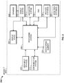
- the processing system 208 includes or otherwise accesses a data storage element 224, such as a memory (e.g., RAM memory, ROM memory, flash memory, registers, a hard disk, or the like) or another suitable non-transitory short or long term storage media capable of storing computer-executable programming instructions or other data for execution that, when read and executed by the processing system 208, cause the processing system 208 to execute and perform one or more of the processes, tasks, operations, and/or functions described herein.
- a data storage element 224 such as a memory (e.g., RAM memory, ROM memory, flash memory, registers, a hard disk, or the like) or another suitable non-transitory short or long term storage media capable of storing computer-executable programming instructions or other data for execution that, when read and executed by the processing system 208, cause the processing system 208 to execute and perform one or more of the processes, tasks, operations, and/or functions described herein.
- a navigational map displayed on the display device 204 may include graphical representations of navigational reference points (e.g., waypoints, navigational aids, distance measuring equipment (DMEs), very high-frequency omnidirectional radio ranges (VORs), and the like), designated special use airspaces, obstacles, and the like overlying the terrain on the map.
- navigational reference points e.g., waypoints, navigational aids, distance measuring equipment (DMEs), very high-frequency omnidirectional radio ranges (VORs), and the like
- DMEs distance measuring equipment
- VORs very high-frequency omnidirectional radio ranges
- the onboard detection system(s) 220 generally represents the component(s) of the aircraft 202 that is coupled to the processing system 208 and/or the display system 210 to generate or otherwise provide information indicative of various objects or regions of interest within the vicinity of the aircraft 202 that are sensed, detected, or otherwise identified by a respective onboard detection system 220.
- an onboard detection system 220 may be realized as a radar system that measures, senses, or otherwise detects other aircraft in the vicinity of the aircraft 202 and provides corresponding radar data (e.g., radar imaging data, range setting data, angle setting data, and/or the like) to one or more of the other onboard systems 208, 210, 214, 216, 218 for further processing and/or handling.
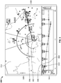
- the illustrated vertical profile display 304 includes a graphical representation of the ownship 302 that is disposed at or near a left edge of the vertical profile display 304 at a vertical position that corresponds to the current altitude of the ownship 302, with the vertical profile of the route 306 extending from the left edge of the vertical profile display 304 towards the right of the vertical profile display 304 with vertical positions at the respective horizontal positions along with the route 306 corresponding to the planned altitude for the ownship 302 at the navigational reference points or geographic locations corresponding to the respective horizontal positions on the vertical profile display 304 with respect to the current aircraft position.
- the ownship 302 is labeled with the flight number "FIXAR" currently on a "184" heading.
- the illustrated navigational map 312 includes a graphical representation of the ownship 302 overlaid or rendered on top of a background.
- the background comprises a graphical representation of the terrain, topology, navigational reference points, airspace designations and/or restrictions, or other suitable items or points of interest corresponding to the currently displayed area of the navigational map, which may be maintained in a terrain database, a navigational database, or another suitable database.
- the display system 210 (of FIG. 2 ) may render a graphical representation of navigational aids (e.g., VORs, VORTACs, DMEs, and the like) and airports within the currently displayed geographic area of the navigational map 312 overlying the background.
- navigational map 312 may also include graphical representations of airspace designations and/or airspace restrictions, cities, towns, roads, railroads, and other information.
- FIG. 3 depicts a top view (e.g., from above the ownship 302) of the navigational map 312 (alternatively referred to as a lateral map or lateral view), in practice, alternative embodiments may utilize various perspective views, such as side views, three-dimensional views (e.g., a three-dimensional synthetic vision display), angular or skewed views, and the like.
- the displayed area of the navigational map 312 corresponds to the geographic area that is currently displayed in the navigational map 312, that is, the field of view about the center location of the navigational map 312.
- the center location of the navigational map 312 comprises a reference location for the middle or geometric center of the navigational map 312, which corresponds to a geographic location.
- the navigational map 312 is associated with the movement of the ownship 302, and the aircraft symbology (ownship 302 and/or background refreshes or otherwise updates as the ownship 302 travels, such that the graphical representation of the ownship 302 is positioned over the terrain background in a manner that accurately reflects the current (e.g., instantaneous or substantially real-time) real-world positioning of the ownship 302 relative to the earth.
- the aircraft symbology is shown as traveling across the navigational map 312 (e.g., by updating the location of the aircraft symbology with respect to the background), while in other embodiments, the aircraft symbology may be located at a fixed position on the navigational map 312 (e.g., by updating the background with respect to the aircraft graphic such that the navigational map 312 is maintained centered on and/or aligned with the aircraft graphic).
- the SRAP aircraft follows initial a path set by the FMS, in this case, having a heading of "184" shown on the navigational map 312 prior to the execution of the SRAP system.
- the graphic user interface (GUI) display 300 in the cockpit gives the pilot the ability to select or evaluate the SRAP aircraft from a set of aircraft displayed on the GUI display 300 in the cockpit, which are in the vicinity of the airport, and can be paired as an SRAP aircraft for an approach with the ownship 302.
- the SRAP procedure can open up additional slots by aircraft paired together and sequenced on a vertically separated approach path to make an approach and a subsequent landing. Hence, before the approval of the SRAP approach the GUI display 300 can receive information from the processing system 208 (of FIG.
- the identified paired aircraft 410 is shown as vertical display profile 304 as aircraft 410 that is situated lower in altitude than ownship 302 during the approach.
- the processing system identifies the paired aircraft performing SRAP approach and indicates the paired aircraft (in this case aircraft 410), the flight path and the approach profile on the navigational map display 320 (i.e., the lateral map display) and the vertical profile display 304 for monitoring by the pilot.
- Coupled means that one element/node/feature is directly or indirectly joined to (or directly or indirectly communicates with) another element/node/feature, and not necessarily mechanically.
- drawings may depict one exemplary arrangement of elements directly connected to one another, additional intervening elements, devices, features, or components may be present in an embodiment of the depicted subject matter.
- certain terminology may also be used herein for the purpose of reference only, and thus are not intended to be limiting.
Landscapes
- Engineering & Computer Science (AREA)
- Aviation & Aerospace Engineering (AREA)
- Physics & Mathematics (AREA)
- General Physics & Mathematics (AREA)
- Radar, Positioning & Navigation (AREA)
- Remote Sensing (AREA)
- Traffic Control Systems (AREA)
Applications Claiming Priority (2)
| Application Number | Priority Date | Filing Date | Title |
|---|---|---|---|
| IN202011025990 | 2020-06-19 | ||
| US16/983,191 US11030907B1 (en) | 2020-06-19 | 2020-08-03 | Methods, systems, and apparatuses for identifying and indicating the secondary runway aiming point (SRAP) approach procedures |
Publications (1)
| Publication Number | Publication Date |
|---|---|
| EP3926607A1 true EP3926607A1 (fr) | 2021-12-22 |
Family
ID=76213116
Family Applications (1)
| Application Number | Title | Priority Date | Filing Date |
|---|---|---|---|
| EP21177508.5A Pending EP3926607A1 (fr) | 2020-06-19 | 2021-06-02 | Procédés, systèmes et appareils permettant d'identifier et d'indiquer les procédures d'approche au point de visée de piste secondaire (srap) |
Country Status (2)
| Country | Link |
|---|---|
| US (1) | US11030907B1 (fr) |
| EP (1) | EP3926607A1 (fr) |
Families Citing this family (4)
| Publication number | Priority date | Publication date | Assignee | Title |
|---|---|---|---|---|
| FR3131402B1 (fr) * | 2021-12-24 | 2024-02-02 | Dassault Aviat | Architecture de commande virtualisee d un aeronef et procede associe. |
| US12165525B2 (en) * | 2022-01-05 | 2024-12-10 | Honeywell International Inc. | Comparative vertical profile displays |
| US12014637B2 (en) * | 2022-05-20 | 2024-06-18 | The Boeing Company | Prioritizing crew alerts |
| KR102861188B1 (ko) * | 2022-07-25 | 2025-09-17 | 주식회사 파블로항공 | 비행체 운행 제어 방법 및 그 장치 |
Citations (4)
| Publication number | Priority date | Publication date | Assignee | Title |
|---|---|---|---|---|
| US20140118188A1 (en) * | 2010-02-04 | 2014-05-01 | Honeywell International Inc. | Methods and systems for presenting weather hazard information on an in-trail procedures display |
| US20170032683A1 (en) * | 2015-07-29 | 2017-02-02 | The Boeing Company | Multiple landing threshold aircraft arrival system |
| EP3428903A1 (fr) * | 2017-07-12 | 2019-01-16 | Honeywell International Inc. | Affichage dans le poste de pilotage d'informations sur le trafic (cdti) assisté par séparation visuelle utilisant un affichage situationnel vertical |
| EP3509052A1 (fr) * | 2018-01-05 | 2019-07-10 | Honeywell International Inc. | Avis de vitesse sécurisée pour systèmes d'approche appariés (pa) de gestion d'intervalle de poste de pilotage (fim) |
Family Cites Families (12)
| Publication number | Priority date | Publication date | Assignee | Title |
|---|---|---|---|---|
| DE19836214C2 (de) | 1998-08-11 | 2000-08-24 | Dfs Deutsche Flugsicherung Gmb | Landeanflugverfahren für Luftfahrzeuge und Instrumentenlandeanlage zur Durchführung dieses Verfahrens |
| US6177888B1 (en) | 1999-09-08 | 2001-01-23 | The Boeing Company | Wake turbulence warning and caution system and method |
| US6963291B2 (en) | 2002-05-17 | 2005-11-08 | The Board Of Trustees Of The Leland Stanford Junior University | Dynamic wake prediction and visualization with uncertainty analysis |
| US6865452B2 (en) | 2002-08-30 | 2005-03-08 | Honeywell International Inc. | Quiet mode operation for cockpit weather displays |
| UA82378C2 (en) | 2003-07-25 | 2008-04-10 | Государственное Учреждение "Федеральное Агентство По Правовой Защите Результатов Интеллектуальной Деятельности Военного, Специального И Двойного Назначения" При Министерстве Юстиции Российской Федерации | Aviation simulator |
| RU2007131794A (ru) | 2007-08-23 | 2009-02-27 | Федеральное государственное учреждение "Федеральное агентство по правовой защите результатов интеллектуальной де тельности военного, специального назначени " при Министерстве юстиции РФ (RU) | Способ и система обеспечения вихревой безопасности летательного аппарата |
| US8219264B1 (en) * | 2009-06-08 | 2012-07-10 | The United States Of America As Represented By The Secretary Of The Air Force | Close formation flight positioning system using air data measurements |
| US9911342B2 (en) | 2015-05-07 | 2018-03-06 | L3 Commmunications Avionics Systems, Inc. | Aircraft wake turbulence awareness |
| FR3050304B1 (fr) * | 2016-04-19 | 2019-06-28 | Airbus Operations | Procede et systeme d'evitement de collision pour un aeronef suiveur d'une formation d'aeronefs par rapport a un aeronef intrus. |
| CN108198462B (zh) | 2018-01-25 | 2018-12-14 | 中国民航大学 | 一种全空域飞机尾流遭遇风险告警系统实现方法 |
| WO2020046998A1 (fr) | 2018-08-27 | 2020-03-05 | Gulfstream Aerospace Corporation | Évitement d'aéronef et de sillage d'aéronef pendant un vol |
| CN110473431A (zh) | 2019-09-17 | 2019-11-19 | 中国民用航空飞行学院 | 一种进近管制空域高度限制下的冲突预测方法 |
-
2020
- 2020-08-03 US US16/983,191 patent/US11030907B1/en active Active
-
2021
- 2021-06-02 EP EP21177508.5A patent/EP3926607A1/fr active Pending
Patent Citations (4)
| Publication number | Priority date | Publication date | Assignee | Title |
|---|---|---|---|---|
| US20140118188A1 (en) * | 2010-02-04 | 2014-05-01 | Honeywell International Inc. | Methods and systems for presenting weather hazard information on an in-trail procedures display |
| US20170032683A1 (en) * | 2015-07-29 | 2017-02-02 | The Boeing Company | Multiple landing threshold aircraft arrival system |
| EP3428903A1 (fr) * | 2017-07-12 | 2019-01-16 | Honeywell International Inc. | Affichage dans le poste de pilotage d'informations sur le trafic (cdti) assisté par séparation visuelle utilisant un affichage situationnel vertical |
| EP3509052A1 (fr) * | 2018-01-05 | 2019-07-10 | Honeywell International Inc. | Avis de vitesse sécurisée pour systèmes d'approche appariés (pa) de gestion d'intervalle de poste de pilotage (fim) |
Non-Patent Citations (1)
| Title |
|---|
| DZIKUS NICLAS: "The Impact of Multiple Runway Aiming Points on Runway Capacity - Technical Capacity of a Single Runway", AIRCRAFT NOISE AND EMISSIONS REDUCTION SYMPOSIUM (ANERS 2015), 1 January 2015 (2015-01-01), pages 1 - 8, XP055858150, Retrieved from the Internet <URL:https://elib.dlr.de/102799/1/ANERS2015_Dzikus.pdf> [retrieved on 20211104] * |
Also Published As
| Publication number | Publication date |
|---|---|
| US11030907B1 (en) | 2021-06-08 |
Similar Documents
| Publication | Publication Date | Title |
|---|---|---|
| US9499279B2 (en) | System and method for displaying runway approach information | |
| EP3125213B1 (fr) | Systèmes à bord d'avion et procédés d'identification de plates-formes d'atterrissage en mouvement | |
| US12033250B2 (en) | Capability envelope display methods and systems | |
| CN104340370B (zh) | 用于在飞机显示装置上显示综合最低引导和安全高度信息的驾驶舱显示器和系统及方法 | |
| EP3309519B1 (fr) | Système pour aéronef et procédé associé permettant d'afficher le cisaillement du vent | |
| EP2355070A2 (fr) | Procédés et systèmes pour entrer des instructions de roulement | |
| EP3926607A1 (fr) | Procédés, systèmes et appareils permettant d'identifier et d'indiquer les procédures d'approche au point de visée de piste secondaire (srap) | |
| US9734727B2 (en) | Aircraft systems and methods to display moving landing platforms | |
| US10854091B2 (en) | Energy management visualization methods and systems | |
| US11525699B2 (en) | Radar vectoring energy management guidance methods and systems | |
| US11574549B2 (en) | Composite vertical profile display systems and methods | |
| US20210020055A1 (en) | Drone detection systems and related presentation methods | |
| EP3628977B1 (fr) | Systèmes et procédés permettant d'associer des données de référence de vol critiques à un symbole de vecteur de trajectoire de vol | |
| EP3985646A1 (fr) | Systèmes et procédés d'affichage de profils verticaux composites | |
| EP4358067A1 (fr) | Procédés et systèmes de vérification de procédure d'aéronef à l'aide d'un curseur virtuel | |
| US12122530B2 (en) | Energy constraint management methods and systems | |
| US10565886B2 (en) | Systems and methods for predicting loss of separation events | |
| US12165525B2 (en) | Comparative vertical profile displays | |
| EP4250270A1 (fr) | Procédés et systèmes de gestion de contraintes d'énergie | |
| EP4209756A1 (fr) | Affichages comparatif de profils verticaux |
Legal Events
| Date | Code | Title | Description |
|---|---|---|---|
| PUAI | Public reference made under article 153(3) epc to a published international application that has entered the european phase |
Free format text: ORIGINAL CODE: 0009012 |
|
| STAA | Information on the status of an ep patent application or granted ep patent |
Free format text: STATUS: THE APPLICATION HAS BEEN PUBLISHED |
|
| AK | Designated contracting states |
Kind code of ref document: A1 Designated state(s): AL AT BE BG CH CY CZ DE DK EE ES FI FR GB GR HR HU IE IS IT LI LT LU LV MC MK MT NL NO PL PT RO RS SE SI SK SM TR |
|
| B565 | Issuance of search results under rule 164(2) epc |
Effective date: 20211116 |
|
| RAP3 | Party data changed (applicant data changed or rights of an application transferred) |
Owner name: HONEYWELL INTERNATIONAL INC. |
|
| STAA | Information on the status of an ep patent application or granted ep patent |
Free format text: STATUS: REQUEST FOR EXAMINATION WAS MADE |
|
| 17P | Request for examination filed |
Effective date: 20220608 |
|
| RBV | Designated contracting states (corrected) |
Designated state(s): AL AT BE BG CH CY CZ DE DK EE ES FI FR GB GR HR HU IE IS IT LI LT LU LV MC MK MT NL NO PL PT RO RS SE SI SK SM TR |
|
| P01 | Opt-out of the competence of the unified patent court (upc) registered |
Effective date: 20230421 |
|
| STAA | Information on the status of an ep patent application or granted ep patent |
Free format text: STATUS: EXAMINATION IS IN PROGRESS |
|
| 17Q | First examination report despatched |
Effective date: 20241107 |
|
| GRAP | Despatch of communication of intention to grant a patent |
Free format text: ORIGINAL CODE: EPIDOSNIGR1 |
|
| STAA | Information on the status of an ep patent application or granted ep patent |
Free format text: STATUS: GRANT OF PATENT IS INTENDED |
|
| RIC1 | Information provided on ipc code assigned before grant |
Ipc: G08G 5/00 20060101AFI20260108BHEP Ipc: G08G 5/21 20250101ALI20260108BHEP Ipc: G08G 5/54 20250101ALI20260108BHEP Ipc: G08G 5/50 20250101ALI20260108BHEP Ipc: G08G 5/72 20250101ALI20260108BHEP |
|
| RIC1 | Information provided on ipc code assigned before grant |
Ipc: G08G 5/00 20060101AFI20260115BHEP Ipc: G08G 5/72 20250101ALI20260115BHEP Ipc: G08G 5/50 20250101ALI20260115BHEP Ipc: G08G 5/54 20250101ALI20260115BHEP Ipc: G08G 5/21 20250101ALI20260115BHEP Ipc: G08G 5/55 20250101ALI20260115BHEP Ipc: G08G 5/25 20250101ALI20260115BHEP |
|
| INTG | Intention to grant announced |
Effective date: 20260202 |