EP3926694A1 - Fotovoltaikanlage - Google Patents
Fotovoltaikanlage Download PDFInfo
- Publication number
- EP3926694A1 EP3926694A1 EP20773410.4A EP20773410A EP3926694A1 EP 3926694 A1 EP3926694 A1 EP 3926694A1 EP 20773410 A EP20773410 A EP 20773410A EP 3926694 A1 EP3926694 A1 EP 3926694A1
- Authority
- EP
- European Patent Office
- Prior art keywords
- cell
- string group
- string
- electrically conductive
- photovoltaic assembly
- Prior art date
- Legal status (The legal status is an assumption and is not a legal conclusion. Google has not performed a legal analysis and makes no representation as to the accuracy of the status listed.)
- Withdrawn
Links
- 239000003550 marker Substances 0.000 claims description 6
- 239000000853 adhesive Substances 0.000 claims description 3
- 230000001070 adhesive effect Effects 0.000 claims description 3
- 238000010586 diagram Methods 0.000 description 22
- 230000000903 blocking effect Effects 0.000 description 7
- 230000000694 effects Effects 0.000 description 7
- 239000011521 glass Substances 0.000 description 7
- 229910000679 solder Inorganic materials 0.000 description 6
- 239000002699 waste material Substances 0.000 description 4
- 230000000712 assembly Effects 0.000 description 3
- 238000000429 assembly Methods 0.000 description 3
- 238000004519 manufacturing process Methods 0.000 description 2
- 239000000463 material Substances 0.000 description 2
- 230000003044 adaptive effect Effects 0.000 description 1
- 238000006243 chemical reaction Methods 0.000 description 1
- 239000003086 colorant Substances 0.000 description 1
- 230000008602 contraction Effects 0.000 description 1
- 210000003298 dental enamel Anatomy 0.000 description 1
- 239000000428 dust Substances 0.000 description 1
- 230000005611 electricity Effects 0.000 description 1
- 210000003608 fece Anatomy 0.000 description 1
- 239000010871 livestock manure Substances 0.000 description 1
- 230000000873 masking effect Effects 0.000 description 1
- 239000002184 metal Substances 0.000 description 1
- 238000012986 modification Methods 0.000 description 1
- 230000004048 modification Effects 0.000 description 1
- 239000012780 transparent material Substances 0.000 description 1
Images






Classifications
-
- H—ELECTRICITY
- H02—GENERATION; CONVERSION OR DISTRIBUTION OF ELECTRIC POWER
- H02S—GENERATION OF ELECTRIC POWER BY CONVERSION OF INFRARED RADIATION, VISIBLE LIGHT OR ULTRAVIOLET LIGHT, e.g. USING PHOTOVOLTAIC [PV] MODULES
- H02S40/00—Components or accessories in combination with PV modules, not provided for in groups H02S10/00 - H02S30/00
- H02S40/30—Electrical components
- H02S40/36—Electrical components characterised by special electrical interconnection means between two or more PV modules, e.g. electrical module-to-module connection
-
- H—ELECTRICITY
- H02—GENERATION; CONVERSION OR DISTRIBUTION OF ELECTRIC POWER
- H02S—GENERATION OF ELECTRIC POWER BY CONVERSION OF INFRARED RADIATION, VISIBLE LIGHT OR ULTRAVIOLET LIGHT, e.g. USING PHOTOVOLTAIC [PV] MODULES
- H02S40/00—Components or accessories in combination with PV modules, not provided for in groups H02S10/00 - H02S30/00
- H02S40/30—Electrical components
- H02S40/34—Electrical components comprising specially adapted electrical connection means to be structurally associated with the PV module, e.g. junction boxes
-
- H—ELECTRICITY
- H10—SEMICONDUCTOR DEVICES; ELECTRIC SOLID-STATE DEVICES NOT OTHERWISE PROVIDED FOR
- H10F—INORGANIC SEMICONDUCTOR DEVICES SENSITIVE TO INFRARED RADIATION, LIGHT, ELECTROMAGNETIC RADIATION OF SHORTER WAVELENGTH OR CORPUSCULAR RADIATION
- H10F19/00—Integrated devices, or assemblies of multiple devices, comprising at least one photovoltaic cell covered by group H10F10/00, e.g. photovoltaic modules
-
- H—ELECTRICITY
- H10—SEMICONDUCTOR DEVICES; ELECTRIC SOLID-STATE DEVICES NOT OTHERWISE PROVIDED FOR
- H10F—INORGANIC SEMICONDUCTOR DEVICES SENSITIVE TO INFRARED RADIATION, LIGHT, ELECTROMAGNETIC RADIATION OF SHORTER WAVELENGTH OR CORPUSCULAR RADIATION
- H10F19/00—Integrated devices, or assemblies of multiple devices, comprising at least one photovoltaic cell covered by group H10F10/00, e.g. photovoltaic modules
- H10F19/70—Integrated devices, or assemblies of multiple devices, comprising at least one photovoltaic cell covered by group H10F10/00, e.g. photovoltaic modules comprising bypass diodes
-
- H—ELECTRICITY
- H10—SEMICONDUCTOR DEVICES; ELECTRIC SOLID-STATE DEVICES NOT OTHERWISE PROVIDED FOR
- H10F—INORGANIC SEMICONDUCTOR DEVICES SENSITIVE TO INFRARED RADIATION, LIGHT, ELECTROMAGNETIC RADIATION OF SHORTER WAVELENGTH OR CORPUSCULAR RADIATION
- H10F19/00—Integrated devices, or assemblies of multiple devices, comprising at least one photovoltaic cell covered by group H10F10/00, e.g. photovoltaic modules
- H10F19/70—Integrated devices, or assemblies of multiple devices, comprising at least one photovoltaic cell covered by group H10F10/00, e.g. photovoltaic modules comprising bypass diodes
- H10F19/75—Integrated devices, or assemblies of multiple devices, comprising at least one photovoltaic cell covered by group H10F10/00, e.g. photovoltaic modules comprising bypass diodes the bypass diodes being integrated or directly associated with the photovoltaic cells, e.g. formed in or on the same substrate
-
- H—ELECTRICITY
- H10—SEMICONDUCTOR DEVICES; ELECTRIC SOLID-STATE DEVICES NOT OTHERWISE PROVIDED FOR
- H10F—INORGANIC SEMICONDUCTOR DEVICES SENSITIVE TO INFRARED RADIATION, LIGHT, ELECTROMAGNETIC RADIATION OF SHORTER WAVELENGTH OR CORPUSCULAR RADIATION
- H10F19/00—Integrated devices, or assemblies of multiple devices, comprising at least one photovoltaic cell covered by group H10F10/00, e.g. photovoltaic modules
- H10F19/80—Encapsulations or containers for integrated devices, or assemblies of multiple devices, having photovoltaic cells
-
- H—ELECTRICITY
- H10—SEMICONDUCTOR DEVICES; ELECTRIC SOLID-STATE DEVICES NOT OTHERWISE PROVIDED FOR
- H10F—INORGANIC SEMICONDUCTOR DEVICES SENSITIVE TO INFRARED RADIATION, LIGHT, ELECTROMAGNETIC RADIATION OF SHORTER WAVELENGTH OR CORPUSCULAR RADIATION
- H10F19/00—Integrated devices, or assemblies of multiple devices, comprising at least one photovoltaic cell covered by group H10F10/00, e.g. photovoltaic modules
- H10F19/90—Structures for connecting between photovoltaic cells, e.g. interconnections or insulating spacers
- H10F19/902—Structures for connecting between photovoltaic cells, e.g. interconnections or insulating spacers for series or parallel connection of photovoltaic cells
-
- H—ELECTRICITY
- H10—SEMICONDUCTOR DEVICES; ELECTRIC SOLID-STATE DEVICES NOT OTHERWISE PROVIDED FOR
- H10F—INORGANIC SEMICONDUCTOR DEVICES SENSITIVE TO INFRARED RADIATION, LIGHT, ELECTROMAGNETIC RADIATION OF SHORTER WAVELENGTH OR CORPUSCULAR RADIATION
- H10F77/00—Constructional details of devices covered by this subclass
- H10F77/93—Interconnections
- H10F77/933—Interconnections for devices having potential barriers
- H10F77/935—Interconnections for devices having potential barriers for photovoltaic devices or modules
- H10F77/937—Busbar structures for modules
-
- Y—GENERAL TAGGING OF NEW TECHNOLOGICAL DEVELOPMENTS; GENERAL TAGGING OF CROSS-SECTIONAL TECHNOLOGIES SPANNING OVER SEVERAL SECTIONS OF THE IPC; TECHNICAL SUBJECTS COVERED BY FORMER USPC CROSS-REFERENCE ART COLLECTIONS [XRACs] AND DIGESTS
- Y02—TECHNOLOGIES OR APPLICATIONS FOR MITIGATION OR ADAPTATION AGAINST CLIMATE CHANGE
- Y02E—REDUCTION OF GREENHOUSE GAS [GHG] EMISSIONS, RELATED TO ENERGY GENERATION, TRANSMISSION OR DISTRIBUTION
- Y02E10/00—Energy generation through renewable energy sources
- Y02E10/50—Photovoltaic [PV] energy
-
- Y—GENERAL TAGGING OF NEW TECHNOLOGICAL DEVELOPMENTS; GENERAL TAGGING OF CROSS-SECTIONAL TECHNOLOGIES SPANNING OVER SEVERAL SECTIONS OF THE IPC; TECHNICAL SUBJECTS COVERED BY FORMER USPC CROSS-REFERENCE ART COLLECTIONS [XRACs] AND DIGESTS
- Y02—TECHNOLOGIES OR APPLICATIONS FOR MITIGATION OR ADAPTATION AGAINST CLIMATE CHANGE
- Y02E—REDUCTION OF GREENHOUSE GAS [GHG] EMISSIONS, RELATED TO ENERGY GENERATION, TRANSMISSION OR DISTRIBUTION
- Y02E70/00—Other energy conversion or management systems reducing GHG emissions
- Y02E70/30—Systems combining energy storage with energy generation of non-fossil origin
Definitions
- the present application relates to the technical field of solar energy, and particularly relates to a photovoltaic assembly.
- Photovoltaic assemblies are devices that convert light energy into electric energy by using the photovoltaic effect.
- it is usually required to connect in series a plurality of cell, to form a cell string, and a plurality of the cell strings may be connected in series or connected in parallel into a cell-string group.
- the blocked cell will become a load, consume the power generated by the other cell, and generate heat, to cause the increase of the local temperature of the assembly, result in the hot-spot effect, and cause the solar cell to have a lower output power or even be burnt down.
- the diode In order to reduce the affection by the hot spot, it is usually required to introduce an diode into the photovoltaic assembly.
- the diode requires to be connected to the two ends of a cell string or cell-string group by a dedicated bus bar to be reversely connected in parallel to the cell string or cell-string group, and when the cell connected in parallel to the diode is blocked, the diode is turned on to enable the cell string or cell-string group where the blocked cell is located to be bypassed by the diode, to prevent the hot-spot effect.
- the arrangement mode of the cell strings or cell-string groups cases emerge that a plurality of cell strings or cell-string groups share one diode.
- a purpose of the present application is to provide a photovoltaic assembly, which can avoid increasing the consumption of the bus bars to a large extent while adding the bypass diodes, and facilitates wiring, to improve the capacity of the photovoltaic assembly of resisting hot spots.
- a photovoltaic assembly wherein the photovoltaic assembly comprises at least one cell unit, and the cell unit is rectangular;
- the cell unit comprises a first cell-string group, a second cell-string group and a third cell-string group;
- the cell unit further comprises a fourth cell-string group, both of the second cell-string group and the third cell-string group are adjacent to the fourth cell-string group, and the third cell-string group is electrically connected to the fourth cell-string group;
- a length of the side edges of the first cell-string group is equal to a length of the electrically conductive ends of the second cell-string group.
- a length of the side edges of the first cell-string group is greater than a length of the electrically conductive ends of the second cell-string group.
- the first cell-string group, the second cell-string group, the third cell-string group and the fourth cell-string group have a same shape.
- the cell unit comprises a first cell-string group, a second cell-string group and a third cell-string group;
- the cell unit further comprises a fourth cell-string group, both of the second cell-string group and the third cell-string group are adjacent to the fourth cell-string group, and the third cell-string group is electrically connected to the fourth cell-string group;
- a length of the side edges of the first cell-string group is equal to a sum between a length of the electrically conductive ends of the second cell-string group and a length of the electrically conductive ends of the third cell-string group.
- a length of the side edges of the first cell-string group is greater than a sum between a length of the electrically conductive ends of the second cell-string group and a length of the electrically conductive ends of the third cell-string group.
- a diode is reversely connected in parallel between the electrically conductive ends of each of the cell-string groups; or at least two neighboring instances of the cell-string groups are reversely connected in parallel to a same diode.
- the photovoltaic assembly further comprises a transparent cover plate covering a front face of the cell unit, a pattern marker is provided at a position on an inner side or outer side of the transparent cover plate that corresponds to a bus bar, and the bus bar electrically connects the electrically conductive ends of neighboring instances of the cell-string groups.
- the photovoltaic assembly further comprises a transparent cover plate covering a front face of the cell unit, a light emitting device is provided at a position of the transparent cover plate that corresponds to the bus bar, the light emitting device is located on an inner side or outer side of the transparent cover plate, and the bus bar electrically connects the electrically conductive ends of neighboring instances of the cell-string groups.
- the photovoltaic assembly further comprises a transparent cover plate covering a front face of the cell unit, the transparent cover plate is provided with a covering layer, an orthographic projection of a pattern of the covering layer on the cell unit matches with a bus bar, and the bus bar electrically connects the electrically conductive ends of neighboring instances of the cell-string groups.
- two neighboring instances of the cell of a same instance of the cell-string groups overlap, and are connect in series by a conductive adhesive or a wire.
- the photovoltaic assembly further comprises a junction box, and the diode is located inside the junction box; or the diode is packaged inside the cell unit.
- one of the electrically conductive ends of one of the cell-string groups and one of the side edges of the neighboring cell-string group are located on a same straight line, and the two neighboring cell-string groups are located at a same side of the straight line, whereby, when the electrically conductive ends of the two cell-string groups are connected by a bus bar, the bus bar can extend between the electrically conductive ends of the cell-string groups, and the extension part can at the same time be used to reversely connect in parallel a diode, thereby reducing the consumption of the bus bars that are provided specially for reversely connecting in parallel the diodes, to save the bus bars.
- a diode may be reversely connected in parallel between the electrically conductive ends of each of the cell-string groups, which can increase the quantity of the diodes, to improve the capacity of the photovoltaic assembly of resisting hot spots.
- the blank region provided on the double-glass assembly may be used to place the junction box and the nameplate, thereby preventing blocking the cell, to eliminate the hot-spot effect.
- 100 cell unit; 101: blank region; 200: cell string; 201: cell; 202: punched solder strips; 300: junction box; 400: nameplate; 1: first cell-string group; 2: second cell-string group; 3: third cell-string group; 4: fourth cell-string group; 5: fifth cell-string group; 6: sixth cell-string group; 7: first bus bar; 8: second bus bar; 9: third bus bar; 10: fourth bus bar; 11: first diode; 12: second diode; 13: third diode; and 14: fourth diode.
- the embodiments of the present application provide a photovoltaic assembly, wherein the photovoltaic assembly comprises at least one cell unit, and the cell unit is rectangular; the cell unit comprises a plurality of cell-string groups that are electrically connected, each of the cell-string groups comprises a plurality of cell strings that are connected in parallel, and each of the cell strings comprises a plurality of cell that are connected in series; each of the cell-string groups has two electrically conductive ends and two side edges located between the two electrically conductive ends; and at least two neighboring instances of the cell-string groups are arranged in a predetermined mode, wherein the predetermined mode is that: one of the electrically conductive ends of one of the cell-string groups and one of the side edges of the neighboring cell-string group are located on a same straight line, and the two neighboring cell-string groups are located at a same side of the straight line.
- one of the electrically conductive ends of one of the cell-string groups and one of the side edges of the neighboring cell-string group are located on a same straight line, and the two neighboring cell-string groups are located at a same side of the straight line, whereby, when the electrically conductive ends of the two cell-string groups are connected by a bus bar, the bus bar can extend between the electrically conductive ends of the cell-string groups, and the extension part can at the same time be used to reversely connect in parallel a diode, thereby reducing the consumption of the bus bars that are provided specially for reversely connecting in parallel the diodes, to save the bus bars.
- the cell string 200 may comprise a plurality of cell 201 that are sequentially connected in series, for example, comprising 2-35 cell 201.
- the cell 201 is the smallest module in the cell string for realizing photovoltaic conversion, and by connecting a plurality of the cell 201 in series to form the cell string, the electricity generation capacity can be increased.
- the type of the cell 201 is not particularly limited herein.
- two neighboring cell 201 may overlap and may be connected in series by a conductive adhesive or a metal wire.
- the cell string 200 may further comprise two punched solder strips 202, wherein one of the punched solder strips 202 is connected to the cathode of the cell string, and the other of the punched solder strips 202 is connected to the anode of the cell string. From the perspective of the manufacturing process, the gap of the punched solder strips provides a room for deformation, which can prevent the electrode failure caused by thermal expansion and contraction of the cell string during the manufacturing process.
- Each of the cell-string groups has two electrically conductive ends and two side edges, the two side edges are located between the two electrically conductive ends, and the two electrically conductive ends are the cathode and the anode of the cell-string groups.
- the cell-string groups may be of a rectangular shape, which include square and oblong. Furthermore, the shapes of the different cell-string groups may be the same or different. Furthermore, the sizes of the different cell-string groups may be the same or different.
- Each two neighboring cell-string groups have a gap therebetween, for a bus bar connecting the cell-string groups to pass through. Bus bars are individually provided at the two electrically conductive ends of the cell string.
- the bus bars are welded to the punched solder strips on the electrically conductive ends of the cell strings to connect at least two neighboring cell strings in parallel to form the cell-string group. Moreover, the neighboring cell-string groups are also connected in parallel or in series by bus bars.
- the photovoltaic assembly is a double-glass double-face assembly
- the cell unit may have a blank region, so as to place the junction box and the nameplate on a transparent cover plate corresponding to the position of the blank region.
- the blank region is formed by enclosure of a plurality of cell-string groups. Certainly, the cell unit may not have the blank region.
- a cell unit formed by two cell-string groups is taken as an example.
- the cell unit 100 comprises a first cell-string group 1 and a second cell-string group 2.
- the first cell-string group 1 and the second cell-string group 2 are adjacently spliced, one of the side edges of the first cell-string group 1 and one of the electrically conductive ends of the second cell-string group 2 are located on a first straight line l 1 , and both of the first cell-string group 1 and the second cell-string group 2 are located on the same side of the first straight line l 1 (the right side of l 1 shown in FIG. 2 ). It can be understood that, in the arrangement mode shown in FIG.
- the length of the side edges of the first cell-string group 1 and the length of the electrically conductive ends of the second cell-string group 2 are equal, whereby the cell unit 100 satisfies a rectangular shape. Therefore, in the photovoltaic assembly according to the embodiment of the present application, when the electrically conductive ends of two neighboring cell-string groups are connected by a bus bar, the bus bar can extend between the electrically conductive ends of the cell-string groups, and the extension part can at the same time be used to reversely connect in parallel a diode, thereby reducing the consumption of the bus bars that are provided specially for reversely connecting in parallel the diodes, to save the bus bars.
- a third cell-string group 3 may be added to form the cell unit 100.
- the first cell-string group 1 and the second cell-string group 2 are located on the same side of the first straight line l 1 , and the third cell-string group 3 is adjacent to both of the first cell-string group 1 and the second cell-string group 2.
- the third cell-string group 3 and the first cell-string group 1 are still required to satisfy a position relation similar to that between the first cell-string group 1 and the second cell-string group 2; in other words, one of the electrically conductive ends of the third cell-string group 3 and one of the side edges of the first cell-string group 1 are located on a second straight line l 2 , and the third cell-string group 3 and the first cell-string group 1 are located on the same side of the second straight line l 2 (the upper side of l 2 shown in FIG. 3 ).
- the length of the side edges of the third cell-string group 3 is equal to the sum between the length of the electrically conductive ends of the first cell-string group 1 and the length of the side edges of the second cell-string group 2. Therefore, such a cell unit comprising three cell-string groups can be used to splice into the photovoltaic assembly, the advantages of which may refer to the first embodiment, and are not discussed here further.
- the third embodiment of the photovoltaic assembly as shown in FIG. 3 , on the basis of the second embodiment, when the length of the side edges of the first cell-string group 1 is equal to the length of the electrically conductive ends of the second cell-string group 2, one of the side edges of the first cell-string group 1 and one of the electrically conductive ends of the second cell-string group 2 are aligned on the first straight line l 1 . It can be easily understood that, in this case, the cell unit 100 formed by three cell-string groups does not have the blank region, which can prevent waste of the planar area.
- the cell unit 100 formed by three cell-string groups has the blank region 101.
- Such a cell unit 100 is particularly suitable for a double-glass double-face assembly, and the junction box and the nameplate may be placed at the blank region, to prevent blocking of the back face of the cell unit by the junction box and the nameplate which results in a hot spot.
- a fourth cell-string group 4 may be added to form the cell unit 100.
- the first cell-string group 1 and the second cell-string group 2 are located on the same side of the first straight line l 1
- the third cell-string group 3 is adjacent to both of the first cell-string group 1 and the second cell-string group 2.
- One of the electrically conductive ends of the third cell-string group 3 and one of the side edges of the first cell-string group 1 are located on a second straight line l 2
- the third cell-string group 3 and the first cell-string group 1 are located on the same side of the second straight line h.
- the fourth cell-string group 4 and the third cell-string group 3 are still required to satisfy a position relation similar to that between the first cell-string group 1 and the second cell-string group 2; in other words, one of the side edges of the third cell-string group 3 and one of the electrically conductive ends of the fourth cell-string group 4 are located on a third straight line l 3 , and the third cell-string group 3 and the fourth cell-string group 4 are located on the same side of the third straight line l 3 (the left side of l 3 shown in FIG. 5 ).
- one of the electrically conductive ends of the second cell-string group 2 and one of the side edges of the fourth cell-string group 4 are located on a fourth straight line l 4
- the second cell-string group 2 and the fourth cell-string group 4 are located on the same side of the fourth straight line l 4 (the lower side of l 4 shown in FIG. 5 ). Therefore, such a cell unit comprising four cell-string groups can be used to splice into the photovoltaic assembly, the advantages of which may refer to the first embodiment, and are not discussed here further.
- the sixth embodiment of the photovoltaic assembly as shown in FIG. 5 , on the basis of the fifth embodiment, when the length of the side edges of the first cell-string group 1 is equal to the length of the electrically conductive ends of the second cell-string group 2, one of the side edges of the first cell-string group 1 and one of the electrically conductive ends of the second cell-string group 2 are aligned on the first straight line l 1 . It can be easily understood that, in this case, the cell unit 100 formed by four cell-string groups does not have the blank region, which can prevent waste of the planar area.
- the seventh embodiment of the photovoltaic assembly as shown in FIG. 6 , on the basis of the fifth embodiment, when the length of the side edges of the first cell-string group 1 is greater than the length of the electrically conductive ends of the second cell-string group 2, along the first straight line l 1 , one of the side edges of the first cell-string group 1 goes beyond one of the electrically conductive ends of the second cell-string group 2.
- the cell unit 100 formed by four cell-string groups has the blank region 101.
- Such a cell unit 100 is particularly suitable for a double-glass double-face assembly, and the junction box and the nameplate may be placed at the blank region, to prevent blocking of the back face of the cell unit by the junction box and the nameplate which results in a hot spot.
- the first cell-string group 1, the second cell-string group 2, the third cell-string group 3 and the fourth cell-string group 4 have the same shape.
- the eighth embodiment of the photovoltaic assembly according to the present application shown in FIG. 7 may be formed, wherein the cell unit 100 has the blank region 101.
- the ninth embodiment of the photovoltaic assembly according to the present application shown in FIG. 8 may be formed, wherein the cell unit 100 does not have the blank region.
- the bus bars are arranged at the edge positions of the cell-string groups according to the present embodiment, that the shape of the cell-string groups is square does not mean that it is an absolutely standard square, but it is an approximate square. If the difference between the lengths of two neighboring side edges of the cell-string groups satisfies the arrangement of the bus bars, that satisfies the square shape according to the present embodiment.
- a third cell-string group 3 may be added to form the cell unit 100.
- Both of the second cell-string group 2 and the third cell-string group 3 are adjacent to the first cell-string group 1, and are located on the same side edge of the first cell-string group 1 (the upper side of the first cell-string group 1 shown in FIG. 9 ).
- the first cell-string group 1 and the second cell-string group 2 are located on the same side of the first straight line l 1 (the right side of l 1 shown in FIG. 9 ), and the third cell-string group 3 is adjacent to both of the first cell-string group 1 and the second cell-string group 2.
- one of the side edges of the third cell-string group 3 and the other of the electrically conductive ends of the first cell-string group 1 are located on the second straight line l 2
- the third cell-string group 3 and the first cell-string group 1 are located on the same side of the second straight line l 2 (the left side of l 2 shown in FIG. 9 ).
- the length of the side edges of the third cell-string group 3 is equal to the length of the side edges of the second cell-string group 2. Therefore, such a cell unit comprising three cell-string groups can be used to splice into the photovoltaic assembly, the advantages of which may refer to the first embodiment, and are not discussed here further.
- the eleventh embodiment of the photovoltaic assembly as shown in FIG. 9 , on the basis of the ninth embodiment, when the length of the side edges of the first cell-string group 1 is equal to the sum between the length of the electrically conductive ends of the second cell-string group 2 and the length of the electrically conductive ends of the third cell-string group 3, it can be easily understood that, in this case, the cell unit 100 formed by three cell-string groups does not have the blank region, which can prevent waste of the planar area.
- the cell unit 100 formed by three cell-string groups has the blank region 101.
- Such a cell unit 100 is particularly suitable for a double-glass double-face assembly, and the junction box and the nameplate may be placed at the blank region, to prevent blocking of the back face of the cell unit by the junction box and the nameplate which results in a hot spot.
- a fourth cell-string group 4 may be added to form the cell unit 100.
- the first cell-string group 1 and the second cell-string group 2 are located on the same side of the first straight line l 1 (the right side of l 1 shown in FIG. 11 ), and the third cell-string group 3 is adjacent to both of the first cell-string group 1 and the second cell-string group 2.
- One of the side edges of the third cell-string group 3 and the other of the electrically conductive ends of the first cell-string group 1 are located on the second straight line l 2 , and the second cell-string group 2 and the third cell-string group 3 are located on the same side edge of the first cell-string group 1 (the upper side of the first cell-string group 1 shown in FIG. 11 ).
- the fourth cell-string group 4 and the first cell-string group 1 are in the form of a symmetrical arrangement.
- both of the second cell-string group 2 and the third cell-string group 3 are adjacent to the fourth cell-string group 4, and are located on the same side edge of the fourth cell-string group 4 (the lower side of the fourth cell-string group 4 shown in FIG.
- one of the electrically conductive ends of the fourth cell-string group 4 and one of the side edges of the second cell-string group 2 are located on the first straight line l 1
- the fourth cell-string group 4 and the second cell-string group 2 are located on the same side of the first straight line l 1 (the right side of l 1 shown in FIG. 11 );
- the other of the electrically conductive ends of the fourth cell-string group 4 and one of the side edges of the third cell-string group 3 are located on the second straight line l 2
- the fourth cell-string group 4 and the third cell-string group 3 are located on the same side of the second straight line l 2 (the left side of l 2 shown in FIG. 11 ). Therefore, such a cell unit comprising four cell-string groups can be used to splice into the photovoltaic assembly, the advantages of which may refer to the first embodiment, and are not discussed here further.
- the fourteenth embodiment of the photovoltaic assembly as shown in FIG. 11 , on the basis of the thirteenth embodiment, when the length of the side edges of the first cell-string group 1 is equal to the sum between the length of the electrically conductive ends of the second cell-string group 2 and the length of the electrically conductive ends of the third cell-string group 3, it can be easily understood that, in this case, the cell unit 100 formed by four cell-string groups does not have the blank region, which can prevent waste of the planar area.
- the cell unit 100 formed by four cell-string groups has the blank region 101.
- Such a cell unit 100 is particularly suitable for a double-glass double-face assembly, and the junction box and the nameplate may be placed at the blank region, to prevent blocking of the back face of the cell unit by the junction box and the nameplate which results in a hot spot.
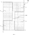
- the cell unit 100 comprises a first cell-string group 1, a second cell-string group 2, a third cell-string group 3, a fourth cell-string group 4, a fifth cell-string group 5 and a sixth cell-string group 6.
- the first cell-string group 1 is adjacent to the second cell-string group 2, one of the electrically conductive ends of the first cell-string group 1 and one of the side edges of the second cell-string group 2 are located on a first straight line l 1 , and the first cell-string group 1 and the second cell-string group 2 are located on the right side of the first straight line l 1 .
- the third cell-string group 3 is adjacent to the first cell-string group 1, one of the electrically conductive ends of the third cell-string group 3 and one of the side edges of the first cell-string group 1 are located on a second straight line l 2 , and the third cell-string group 3 and the first cell-string group 1 are located on the upper side of the second straight line h.
- the fourth cell-string group 4 and the first cell-string group 1 are centrosymmetric with respect to the center of the cell unit 100
- the fifth cell-string group 5 and the second cell-string group 2 are centrosymmetric with respect to the center of the cell unit 100
- the sixth cell-string group 6 and the third cell-string group 3 are centrosymmetric with respect to the center of the cell unit 100.
- the fifth cell-string group 5 and the sixth cell-string group 6 are individually adjacent to the fourth cell-string group 4, and one of the side edges of the fifth cell-string group 5 and one of the electrically conductive ends of the fourth cell-string group 4 are located on a third straight line l 3 ; at the same time, the fifth cell-string group 5 is further adjacent to the third cell-string group 3, one of the side edges of the fifth cell-string group 5 and one of the side edges of the third cell-string group 3 are located on the third straight line l 3 , and all of the fifth cell-string group 5, the fourth cell-string group 4 and the third cell-string group 3 are located on the left of the third straight line l 3 .
- One of the electrically conductive ends of the sixth cell-string group 6 and one of the side edges of the fourth cell-string group 4 are located on a fourth straight line l 4 , and the sixth cell-string group 6 and the fourth cell-string group 4 are located on the lower side of the fourth straight line 14; at the same time, the sixth cell-string group 6 is further adjacent to the second cell-string group 2, one of the side edges of the sixth cell-string group 6 is adjacent to one of the side edges of the second cell-string group 2, and all of the sixth cell-string group 6, the second cell-string group 2 and the first cell-string group 1 are located on the right side of the first straight line l 1 .
- the fourth cell-string group 4 and the first cell-string group 1 have the same shapes and sizes
- the fifth cell-string group 5 and the second cell-string group 2 have the same shapes and sizes
- the sixth cell-string group 6 and the third cell-string group 3 have the same shapes and sizes.
- the length of the side edges of the first cell-string group 1 is greater than the length of the electrically conductive ends of the second cell-string group 2
- the length of the side edges of the fourth cell-string group 4 is greater than the length of the electrically conductive ends of the fifth cell-string group 5.
- the cell unit 100 formed by six cell-string groups has the blank region, and the junction box and the nameplate may be placed at the blank region, to prevent blocking of the back face of the cell unit by the junction box and the nameplate which results in a hot spot.
- the cell unit 100 also has the advantageous effects of the first embodiment.
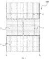
- the quantity and the distribution mode of the cell-string groups of the cell unit 100 are the same as those of the sixteenth embodiment.
- the lengths of the electrically conductive ends of the second cell-string group 2 and the fifth cell-string group 5 are equal to the lengths of the side edges of the first cell-string group 1 and the fourth cell-string group 4, whereby the cell unit 100 does not have the blank region.
- the cell unit 100 also employs the arrangement mode of centrosymmetry, in another aspect, it may also be designed that the sum between the lengths of the electrically conductive ends of the second cell-string group 2 and the fifth cell-string group 5 is equal to the sum between one of the side edges of the first cell-string group 1 and one of the electrically conductive ends of the third cell-string group 3, to form the cell unit 100 that does not have the blank region.
- the photovoltaic assembly comprises two cell units 100 that are distributed rectangularly, and the two cell units 100 are distributed symmetrically with respect to a straight line therebetween.
- the cell units 100 may be cell units 100 that have the blank region.
- FIG. 15 provides an example in which the cell units 100 are the cell unit 100 according to the eighth embodiment, whereby the photovoltaic assembly has two blank regions 101.
- the cell units 100 may also be the cell unit 100 that has the blank region according to the other embodiments such as FIG. 6 , which is not limited in the present disclosure.
- the photovoltaic assembly comprises two cell units 100 that are distributed rectangularly, and the two cell units 100 are distributed symmetrically with respect to a straight line therebetween.
- the cell units 100 may be cell units 100 that do not have the blank region.
- FIG. 16 provides an example in which the cell units 100 are the cell unit 100 according to the ninth embodiment, whereby the photovoltaic assembly does not have the blank region.
- the cell units 100 may also be the cell unit 100 that does not have the blank region according to the other embodiments such as FIG. 5 , which is not limited in the present disclosure.
- the photovoltaic assembly comprises two cell units 100 that are distributed rectangularly, wherein one of the cell units 100 is the cell unit 100 that has the blank region (for example, the cell unit 100 according to the eighth embodiment), and the other of the cell units 100 is the cell unit 100 that does not have the blank region (for example, the cell unit 100 according to the ninth embodiment).
- the sizes of the two cell units are merely required to satisfy the condition that they can be spliced into a rectangle, and are not limited in the present disclosure. Therefore, a blank region can be formed in the photovoltaic assembly.
- a diode may be reversely connected in parallel between the electrically conductive ends of each of the cell-string groups, thereby increasing the quantity of the diodes, to improve the capacity of the assembly of resisting hot spots.
- one diode may also be reversely connected in parallel with a plurality of cell-string groups; for example, at least two neighboring instances of the cell-string groups are reversely connected in parallel to a same diode.
- the modes of the electric connection between the cell-string groups may be, according to demands, series connection, firstly series connection and subsequently parallel connection, or firstly parallel connection and subsequently series connection.
- the cell unit formed by four cell-string groups shown in FIG. 5 is taken as an example.
- the first mode may be that the fourth cell-string group 4, the second cell-string group 2, the first cell-string group 1 and the third cell-string group 3 are head-tail connected (in other words, one of the electrically conductive ends of the preceding one cell-string group is electrically connected to one of the electrically conductive ends of the subsequent one cell-string group), the spare electrically conductive end of the fourth cell-string group 4 is used as the cathode, and the spare electrically conductive end of the third cell-string group 3 is used as the anode, wherein each of the cell-string groups is reversely connected in parallel to one diode.
- the second mode may be that the fourth cell-string group 4, the second cell-string group 2, the first cell-string group 1 and the third cell-string group 3 are head-tail connected, the spare electrically conductive end of the fourth cell-string group 4 is used as the cathode, and the spare electrically conductive end of the third cell-string group 3 is used as the anode, wherein one diode is reversely connected in parallel between the fourth cell-string group 4 and the second cell-string group 2, the fourth cell-string group 4 and the second cell-string group 2 share the same diode, one diode is reversely connected in parallel between the first cell-string group 1 and the third cell-string group 3, and the first cell-string group 1 and the third cell-string group 3 share the same diode.
- the third mode may be that the second cell-string group 2, the first cell-string group 1, the third cell-string group 3 and the fourth cell-string group 4 are head-tail connected, the spare electrically conductive end of the second cell-string group 2 is used as the cathode, and the spare electrically conductive end of the fourth cell-string group 4 is used as the anode, wherein each of the cell-string groups is reversely connected in parallel to one diode.
- the fourth mode may be that the second cell-string group 2, the first cell-string group 1, the third cell-string group 3 and the fourth cell-string group 4 are head-tail connected, the spare electrically conductive end of the second cell-string group 2 is used as the cathode, and the spare electrically conductive end of the fourth cell-string group 4 is used as the anode, wherein one diode is reversely connected in parallel between the second cell-string group 2 and the first cell-string group 1, the second cell-string group 2 and the first cell-string group 1 share the same diode, one diode is reversely connected in parallel between the third cell-string group 3 and the fourth cell-string group 4, and the third cell-string group 3 and the fourth cell-string group 4 share the same diode.
- the series connection may follow other sequences, which may refer to the above description by analogy, and is not discussed further.
- the cathode and anode defined in the above description are merely considered as one mode, and it can be understood that, in practical implementations, the cathode and the anode are relative, the positions of the electrodes may be exchanged, and the connection directions of the diodes may be adaptively adjusted.
- the first mode may be that the fourth cell-string group 4 is connected in series to the second cell-string group 2, the first cell-string group 1 is connected in series to the third cell-string group 3, then the two strings are connected in parallel, one electrically conductive end of the fourth cell-string group 4 that is connected in parallel to the third cell-string group 3 is used as the cathode, and one electrically conductive end of the first cell-string group 1 that is connected in parallel to the second cell-string group 2 is used as the anode, wherein each of the cell-string groups is reversely connected in parallel to one diode.
- the second mode may be that the fourth cell-string group 4 is connected in series to the third cell-string group 3, the first cell-string group 1 is connected in series to the second cell-string group 2, then the two strings are connected in parallel, one electrically conductive end of the second cell-string group 2 that is connected in parallel to the fourth cell-string group 4 is used as the cathode, and one electrically conductive end of the third cell-string group 3 that is connected in parallel to the first cell-string group 1 is used as the anode, wherein each of the cell-string groups is reversely connected in parallel to one diode. It can be understood that, as compared with the first mode, it is merely required to adaptively adjust the connection directions of the diodes.
- firstly series connection and subsequently parallel connection may follow other sequences, which may refer to the above description by analogy, and is not discussed further.
- cathode and anode defined in the above description are merely considered as one mode, and it can be understood that, in practical implementations, the cathode and the anode are relative, the positions of the electrodes may be exchanged, and the connection directions of the diodes may be adaptively adjusted.
- three diodes can be added, which facilitates to improve the performance of resisting hot spots of the photovoltaic assembly.
- the first mode may be that the fourth cell-string group 4 is connected in parallel to the second cell-string group 2, the fourth cell-string group 4 and the second cell-string group 2 share the same diode, the first cell-string group 1 is connected in parallel to the third cell-string group 3, the first cell-string group 1 and the third cell-string group 3 share the same diode, then the two sets are connected in series, and, after the series connection, the two spare ends are individually used as the cathode and the anode.
- the second mode may be that the fourth cell-string group 4 is connected in parallel to the third cell-string group 3, the fourth cell-string group 4 and the third cell-string group 3 share the same diode, the first cell-string group 1 is connected in parallel to the second cell-string group 2, the first cell-string group 1 and the second cell-string group 2 share the same diode, then the two sets are connected in series, and, after the series connection, the two spare ends are individually used as the cathode and the anode.
- the mode of firstly parallel connection and subsequently series connection may follow other sequences, which may refer to the above description by analogy, and is not discussed further.
- one diode can be added, which facilitates to improve the performance of resisting hot spots of the photovoltaic assembly.
- the first cell-string group 1 and the second cell-string group 2 may be connected by a first bus bar 7
- the first cell-string group 1 and the third cell-string group 3 may be connected by a second bus bar 8
- the third cell-string group 3 and the fourth cell-string group 4 may be connected by a third bus bar 9
- the fourth cell-string group 4 and the second cell-string group 2 may be connected by a fourth bus bar 10.
- a first diode 11 is connected between the first bus bar 7 and the second bus bar 8
- a second diode 12 is connected between the second bus bar 8 and the third bus bar 9
- a third diode 13 is connected between the first bus bar 7 and the fourth bus bar 10
- a fourth diode 14 is connected between the third bus bar 9 and the fourth bus bar 10.
- the photovoltaic assembly may further comprise a junction box 300, and the diodes may be located inside the junction box 300.
- the junction box 300 may be located at the blank region.
- the diodes may also be directly connected to the bus bars, and packaged inside the cell unit 100.
- FIG. 19 shows the back face of the eleventh embodiment of the photovoltaic assembly (see FIG. 9 ), wherein the junction box 300 is provided at the back face of the cell unit 100.
- FIG. 20 shows the back face of the eighth embodiment of the photovoltaic assembly (see FIG. 7 ), wherein the junction box 300 and a nameplate 400 may be provided within the blank region 101, the quantity of the junction box 300 is one, and all of the diodes are located inside the junction box 300.
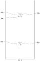
- FIG. 21 shows the back face of the seventh embodiment (see FIG. 6 ), the fifteenth embodiment (see FIG. 12 ) and the sixteenth embodiment (see FIG. 13 ) of the photovoltaic assembly.
- the junction box 300 and a nameplate 400 may be provided within the blank region 101.
- the quantity of the junction box 300 is two, the diodes are located individually inside the two junction boxes 300, and the two junction boxes 300 are located at the two side edges of the nameplate 400.
- FIG. 22 shows the back face of the eighteenth embodiment of the photovoltaic assembly (see FIG. 15 ).
- the photovoltaic assembly comprises two blank regions 101, and the junction box 300 and a nameplate 400 may be provided within each of the blank regions 101.
- the photovoltaic assembly according to the present application may further comprise a transparent cover plate, wherein the material of the transparent cover plate may be glass or other transparent materials.
- the transparent cover plate may cover one side of the cell unit, and a pattern marker may be provided at a position on the inner side or outer side of the transparent cover plate that corresponds to a bus bar, and the bus bar electrically connects the electrically conductive ends of neighboring instances of the cell-string groups.
- a pattern marker may be provided at a position on the inner side or outer side of the transparent cover plate that corresponds to the blank region 101.
- the position of the blank region 101 may refer to the region where the different bus bars, after extending, converge, and may also refer to the completely blank region in the region where the different bus bars, after extending, converge.
- the inner side of the transparent cover plate refers to the one side of the transparent cover plate that is closer to the cell unit, and the outer side of the transparent cover plate refers to the one side of the transparent cover plate that is further away from the cell unit.
- the particular structure of the pattern marker is not particularly limited herein.
- the pattern marker may be an advertisement identifier that is fixed to the blank region by adhesion or in other manners, and so on.
- the transparent cover plate is provided with a light emitting device at the position corresponding to the blank region 101 or the bus bar, and the light emitting device is located on an inner side or outer side of the transparent cover plate.
- the light emitting device may be an LED lamp or other light emitting devices, as long as it can emit light.
- the color of the emitted light of the light emitting device is not particularly limited.
- the transparent cover plate covers the front face of the cell unit, the transparent cover plate is provided with a covering layer, and the orthographic projection of the pattern of the covering layer on the cell unit matches with the bus bar or the blank region 101, thereby masking the bus bar in the gap or the junction box in the blank region by using the covering layer.
- the material of the covering layer may be an enamel layer, and its color may be white, black, blue or other colors.
Landscapes
- Photovoltaic Devices (AREA)
Applications Claiming Priority (4)
| Application Number | Priority Date | Filing Date | Title |
|---|---|---|---|
| CN201910213440.8A CN110034201B (zh) | 2019-03-20 | 2019-03-20 | 光伏组件 |
| CN201910213452.0A CN110034202B (zh) | 2019-03-20 | 2019-03-20 | 光伏组件 |
| CN201910213436.1A CN110034200B (zh) | 2019-03-20 | 2019-03-20 | 光伏组件 |
| PCT/CN2020/076929 WO2020186987A1 (zh) | 2019-03-20 | 2020-02-27 | 光伏组件 |
Publications (2)
| Publication Number | Publication Date |
|---|---|
| EP3926694A1 true EP3926694A1 (de) | 2021-12-22 |
| EP3926694A4 EP3926694A4 (de) | 2022-11-23 |
Family
ID=72519618
Family Applications (1)
| Application Number | Title | Priority Date | Filing Date |
|---|---|---|---|
| EP20773410.4A Withdrawn EP3926694A4 (de) | 2019-03-20 | 2020-02-27 | Fotovoltaikanlage |
Country Status (3)
| Country | Link |
|---|---|
| US (1) | US20220131497A1 (de) |
| EP (1) | EP3926694A4 (de) |
| WO (1) | WO2020186987A1 (de) |
Families Citing this family (4)
| Publication number | Priority date | Publication date | Assignee | Title |
|---|---|---|---|---|
| CN112909114A (zh) * | 2021-02-09 | 2021-06-04 | 苏州宇邦新型材料股份有限公司 | 一种导电结构及光伏组件 |
| CN114388641B (zh) * | 2021-11-03 | 2023-06-23 | 浙江晶科能源有限公司 | 一种光伏组件及光伏组件阵列 |
| CN115621349A (zh) * | 2022-11-10 | 2023-01-17 | 明冠新材料股份有限公司 | 太阳能硅片连接结构及光伏组件 |
| CN117600698B (zh) * | 2024-01-22 | 2024-05-03 | 苏州小牛自动化设备有限公司 | 一种电池串排版焊接方法及设备 |
Family Cites Families (10)
| Publication number | Priority date | Publication date | Assignee | Title |
|---|---|---|---|---|
| KR101081236B1 (ko) * | 2009-10-06 | 2011-11-08 | 엘지이노텍 주식회사 | 태양광 발전장치 |
| CN202454589U (zh) * | 2012-02-13 | 2012-09-26 | 信息产业电子第十一设计研究院科技工程股份有限公司 | 一种改进的太阳能光伏组件 |
| CN103441163B (zh) * | 2013-09-06 | 2016-08-17 | 友达光电股份有限公司 | 太阳能面板 |
| JP2016152721A (ja) * | 2015-02-18 | 2016-08-22 | シャープ株式会社 | 光発電デバイス |
| US20170170336A1 (en) * | 2015-12-14 | 2017-06-15 | Solarcity Corporation | Systems and methods for routing wires in a solar module |
| US20180358491A1 (en) * | 2017-06-12 | 2018-12-13 | The Boeing Company | Solar cell array with bypassed solar cells |
| NL2019318B1 (en) * | 2017-07-21 | 2019-01-30 | Tno | Photovoltaic module |
| CN110034200B (zh) * | 2019-03-20 | 2024-03-12 | 泰州隆基光伏科技有限公司 | 光伏组件 |
| CN110034201B (zh) * | 2019-03-20 | 2023-12-01 | 隆基绿能科技股份有限公司 | 光伏组件 |
| CN110034202B (zh) * | 2019-03-20 | 2024-01-12 | 泰州隆基光伏科技有限公司 | 光伏组件 |
-
2020
- 2020-02-27 WO PCT/CN2020/076929 patent/WO2020186987A1/zh not_active Ceased
- 2020-02-27 EP EP20773410.4A patent/EP3926694A4/de not_active Withdrawn
- 2020-02-27 US US17/440,764 patent/US20220131497A1/en not_active Abandoned
Also Published As
| Publication number | Publication date |
|---|---|
| EP3926694A4 (de) | 2022-11-23 |
| US20220131497A1 (en) | 2022-04-28 |
| WO2020186987A1 (zh) | 2020-09-24 |
Similar Documents
| Publication | Publication Date | Title |
|---|---|---|
| EP3926694A1 (de) | Fotovoltaikanlage | |
| TWI631720B (zh) | 太陽能電池組件 | |
| KR101820376B1 (ko) | 태양광 모듈 | |
| KR20100097219A (ko) | Pv 스트링으로 에지 액세스를 수행하는 광전지 모듈, 연결 방법, 장치, 및 시스템 | |
| CN104576792A (zh) | 太阳能电池片、太阳能电池组件和旁路二极管的组装方法 | |
| US8829338B2 (en) | Bridging solar cell and solar energy system | |
| US20160111573A1 (en) | Highly densified pv module | |
| KR102272506B1 (ko) | 태양 전지 모듈 | |
| US12431840B2 (en) | Solar module and method for fabricating the same | |
| EP3127167A1 (de) | Pv-modul | |
| JP2007128972A (ja) | 太陽電池モジュール用端子ボックス | |
| JP7266444B2 (ja) | 太陽電池モジュール、及び太陽電池システム | |
| CN108566158A (zh) | 一种光伏电池组件 | |
| CN110034201B (zh) | 光伏组件 | |
| US20110226305A1 (en) | Connection device for solar cell module | |
| CN110034202B (zh) | 光伏组件 | |
| CN205039772U (zh) | 太阳能电池模块 | |
| CN110034200B (zh) | 光伏组件 | |
| JP2013012629A (ja) | 太陽光発電システム | |
| CN209785958U (zh) | 光伏组件 | |
| CN209804687U (zh) | 光伏组件 | |
| CN209785959U (zh) | 光伏组件 | |
| KR101893816B1 (ko) | 태양광 모듈 | |
| CN114156352B (zh) | 电池板及光伏组件 | |
| CN108566160B (zh) | 带有多通道电源管理模块的智能接线盒 |
Legal Events
| Date | Code | Title | Description |
|---|---|---|---|
| STAA | Information on the status of an ep patent application or granted ep patent |
Free format text: STATUS: THE INTERNATIONAL PUBLICATION HAS BEEN MADE |
|
| PUAI | Public reference made under article 153(3) epc to a published international application that has entered the european phase |
Free format text: ORIGINAL CODE: 0009012 |
|
| STAA | Information on the status of an ep patent application or granted ep patent |
Free format text: STATUS: REQUEST FOR EXAMINATION WAS MADE |
|
| 17P | Request for examination filed |
Effective date: 20210916 |
|
| AK | Designated contracting states |
Kind code of ref document: A1 Designated state(s): AL AT BE BG CH CY CZ DE DK EE ES FI FR GB GR HR HU IE IS IT LI LT LU LV MC MK MT NL NO PL PT RO RS SE SI SK SM TR |
|
| DAV | Request for validation of the european patent (deleted) | ||
| DAX | Request for extension of the european patent (deleted) | ||
| A4 | Supplementary search report drawn up and despatched |
Effective date: 20221026 |
|
| RIC1 | Information provided on ipc code assigned before grant |
Ipc: H02S 40/38 20140101ALI20221020BHEP Ipc: H02S 40/36 20140101ALI20221020BHEP Ipc: H01L 31/044 20140101ALI20221020BHEP Ipc: H01L 31/05 20140101ALI20221020BHEP Ipc: H01L 31/042 20140101AFI20221020BHEP |
|
| REG | Reference to a national code |
Ref country code: DE Ref legal event code: R079 Free format text: PREVIOUS MAIN CLASS: H01L0031050000 Ipc: H01L0031042000 |
|
| GRAP | Despatch of communication of intention to grant a patent |
Free format text: ORIGINAL CODE: EPIDOSNIGR1 |
|
| STAA | Information on the status of an ep patent application or granted ep patent |
Free format text: STATUS: GRANT OF PATENT IS INTENDED |
|
| RIC1 | Information provided on ipc code assigned before grant |
Ipc: H02S 40/34 20140101ALI20230814BHEP Ipc: H01L 31/05 20140101ALI20230814BHEP Ipc: H01L 31/044 20140101ALI20230814BHEP Ipc: H02S 40/36 20140101ALI20230814BHEP Ipc: H02S 40/38 20140101ALI20230814BHEP Ipc: H01L 31/042 20140101AFI20230814BHEP |
|
| INTG | Intention to grant announced |
Effective date: 20230911 |
|
| STAA | Information on the status of an ep patent application or granted ep patent |
Free format text: STATUS: THE APPLICATION IS DEEMED TO BE WITHDRAWN |
|
| 18D | Application deemed to be withdrawn |
Effective date: 20240123 |