EP3926752A1 - Batterie und tragbare elektrische vorrichtung - Google Patents
Batterie und tragbare elektrische vorrichtung Download PDFInfo
- Publication number
- EP3926752A1 EP3926752A1 EP20199282.3A EP20199282A EP3926752A1 EP 3926752 A1 EP3926752 A1 EP 3926752A1 EP 20199282 A EP20199282 A EP 20199282A EP 3926752 A1 EP3926752 A1 EP 3926752A1
- Authority
- EP
- European Patent Office
- Prior art keywords
- welding
- tab
- battery
- line
- electrode
- Prior art date
- Legal status (The legal status is an assumption and is not a legal conclusion. Google has not performed a legal analysis and makes no representation as to the accuracy of the status listed.)
- Granted
Links
Images



Classifications
-
- H—ELECTRICITY
- H01—ELECTRIC ELEMENTS
- H01M—PROCESSES OR MEANS, e.g. BATTERIES, FOR THE DIRECT CONVERSION OF CHEMICAL ENERGY INTO ELECTRICAL ENERGY
- H01M50/00—Constructional details or processes of manufacture of the non-active parts of electrochemical cells other than fuel cells, e.g. hybrid cells
- H01M50/50—Current conducting connections for cells or batteries
- H01M50/531—Electrode connections inside a battery casing
- H01M50/536—Electrode connections inside a battery casing characterised by the method of fixing the leads to the electrodes, e.g. by welding
-
- H—ELECTRICITY
- H01—ELECTRIC ELEMENTS
- H01M—PROCESSES OR MEANS, e.g. BATTERIES, FOR THE DIRECT CONVERSION OF CHEMICAL ENERGY INTO ELECTRICAL ENERGY
- H01M50/00—Constructional details or processes of manufacture of the non-active parts of electrochemical cells other than fuel cells, e.g. hybrid cells
- H01M50/50—Current conducting connections for cells or batteries
- H01M50/531—Electrode connections inside a battery casing
-
- B—PERFORMING OPERATIONS; TRANSPORTING
- B23—MACHINE TOOLS; METAL-WORKING NOT OTHERWISE PROVIDED FOR
- B23K—SOLDERING OR UNSOLDERING; WELDING; CLADDING OR PLATING BY SOLDERING OR WELDING; CUTTING BY APPLYING HEAT LOCALLY, e.g. FLAME CUTTING; WORKING BY LASER BEAM
- B23K26/00—Working by laser beam, e.g. welding, cutting or boring
- B23K26/20—Bonding
- B23K26/21—Bonding by welding
- B23K26/22—Spot welding
-
- B—PERFORMING OPERATIONS; TRANSPORTING
- B23—MACHINE TOOLS; METAL-WORKING NOT OTHERWISE PROVIDED FOR
- B23K—SOLDERING OR UNSOLDERING; WELDING; CLADDING OR PLATING BY SOLDERING OR WELDING; CUTTING BY APPLYING HEAT LOCALLY, e.g. FLAME CUTTING; WORKING BY LASER BEAM
- B23K26/00—Working by laser beam, e.g. welding, cutting or boring
- B23K26/20—Bonding
- B23K26/21—Bonding by welding
- B23K26/24—Seam welding
- B23K26/244—Overlap seam welding
-
- B—PERFORMING OPERATIONS; TRANSPORTING
- B23—MACHINE TOOLS; METAL-WORKING NOT OTHERWISE PROVIDED FOR
- B23K—SOLDERING OR UNSOLDERING; WELDING; CLADDING OR PLATING BY SOLDERING OR WELDING; CUTTING BY APPLYING HEAT LOCALLY, e.g. FLAME CUTTING; WORKING BY LASER BEAM
- B23K26/00—Working by laser beam, e.g. welding, cutting or boring
- B23K26/20—Bonding
- B23K26/21—Bonding by welding
- B23K26/24—Seam welding
- B23K26/26—Seam welding of rectilinear seams
-
- H—ELECTRICITY
- H01—ELECTRIC ELEMENTS
- H01M—PROCESSES OR MEANS, e.g. BATTERIES, FOR THE DIRECT CONVERSION OF CHEMICAL ENERGY INTO ELECTRICAL ENERGY
- H01M10/00—Secondary cells; Manufacture thereof
- H01M10/04—Construction or manufacture in general
- H01M10/049—Processes for forming or storing electrodes in the battery container
-
- H—ELECTRICITY
- H01—ELECTRIC ELEMENTS
- H01M—PROCESSES OR MEANS, e.g. BATTERIES, FOR THE DIRECT CONVERSION OF CHEMICAL ENERGY INTO ELECTRICAL ENERGY
- H01M4/00—Electrodes
- H01M4/02—Electrodes composed of, or comprising, active material
- H01M4/13—Electrodes for accumulators with non-aqueous electrolyte, e.g. for lithium-accumulators; Processes of manufacture thereof
-
- H—ELECTRICITY
- H01—ELECTRIC ELEMENTS
- H01M—PROCESSES OR MEANS, e.g. BATTERIES, FOR THE DIRECT CONVERSION OF CHEMICAL ENERGY INTO ELECTRICAL ENERGY
- H01M4/00—Electrodes
- H01M4/02—Electrodes composed of, or comprising, active material
- H01M4/13—Electrodes for accumulators with non-aqueous electrolyte, e.g. for lithium-accumulators; Processes of manufacture thereof
- H01M4/139—Processes of manufacture
-
- H—ELECTRICITY
- H01—ELECTRIC ELEMENTS
- H01M—PROCESSES OR MEANS, e.g. BATTERIES, FOR THE DIRECT CONVERSION OF CHEMICAL ENERGY INTO ELECTRICAL ENERGY
- H01M50/00—Constructional details or processes of manufacture of the non-active parts of electrochemical cells other than fuel cells, e.g. hybrid cells
- H01M50/50—Current conducting connections for cells or batteries
- H01M50/543—Terminals
- H01M50/564—Terminals characterised by their manufacturing process
- H01M50/566—Terminals characterised by their manufacturing process by welding, soldering or brazing
-
- B—PERFORMING OPERATIONS; TRANSPORTING
- B23—MACHINE TOOLS; METAL-WORKING NOT OTHERWISE PROVIDED FOR
- B23K—SOLDERING OR UNSOLDERING; WELDING; CLADDING OR PLATING BY SOLDERING OR WELDING; CUTTING BY APPLYING HEAT LOCALLY, e.g. FLAME CUTTING; WORKING BY LASER BEAM
- B23K2101/00—Articles made by soldering, welding or cutting
- B23K2101/36—Electric or electronic devices
-
- B—PERFORMING OPERATIONS; TRANSPORTING
- B23—MACHINE TOOLS; METAL-WORKING NOT OTHERWISE PROVIDED FOR
- B23K—SOLDERING OR UNSOLDERING; WELDING; CLADDING OR PLATING BY SOLDERING OR WELDING; CUTTING BY APPLYING HEAT LOCALLY, e.g. FLAME CUTTING; WORKING BY LASER BEAM
- B23K2101/00—Articles made by soldering, welding or cutting
- B23K2101/36—Electric or electronic devices
- B23K2101/38—Conductors
-
- B—PERFORMING OPERATIONS; TRANSPORTING
- B23—MACHINE TOOLS; METAL-WORKING NOT OTHERWISE PROVIDED FOR
- B23K—SOLDERING OR UNSOLDERING; WELDING; CLADDING OR PLATING BY SOLDERING OR WELDING; CUTTING BY APPLYING HEAT LOCALLY, e.g. FLAME CUTTING; WORKING BY LASER BEAM
- B23K2103/00—Materials to be soldered, welded or cut
- B23K2103/08—Non-ferrous metals or alloys
- B23K2103/10—Aluminium or alloys thereof
-
- B—PERFORMING OPERATIONS; TRANSPORTING
- B23—MACHINE TOOLS; METAL-WORKING NOT OTHERWISE PROVIDED FOR
- B23K—SOLDERING OR UNSOLDERING; WELDING; CLADDING OR PLATING BY SOLDERING OR WELDING; CUTTING BY APPLYING HEAT LOCALLY, e.g. FLAME CUTTING; WORKING BY LASER BEAM
- B23K2103/00—Materials to be soldered, welded or cut
- B23K2103/08—Non-ferrous metals or alloys
- B23K2103/12—Copper or alloys thereof
-
- B—PERFORMING OPERATIONS; TRANSPORTING
- B23—MACHINE TOOLS; METAL-WORKING NOT OTHERWISE PROVIDED FOR
- B23K—SOLDERING OR UNSOLDERING; WELDING; CLADDING OR PLATING BY SOLDERING OR WELDING; CUTTING BY APPLYING HEAT LOCALLY, e.g. FLAME CUTTING; WORKING BY LASER BEAM
- B23K2103/00—Materials to be soldered, welded or cut
- B23K2103/18—Dissimilar materials
-
- H—ELECTRICITY
- H01—ELECTRIC ELEMENTS
- H01M—PROCESSES OR MEANS, e.g. BATTERIES, FOR THE DIRECT CONVERSION OF CHEMICAL ENERGY INTO ELECTRICAL ENERGY
- H01M2220/00—Batteries for particular applications
- H01M2220/30—Batteries in portable systems, e.g. mobile phone, laptop
-
- Y—GENERAL TAGGING OF NEW TECHNOLOGICAL DEVELOPMENTS; GENERAL TAGGING OF CROSS-SECTIONAL TECHNOLOGIES SPANNING OVER SEVERAL SECTIONS OF THE IPC; TECHNICAL SUBJECTS COVERED BY FORMER USPC CROSS-REFERENCE ART COLLECTIONS [XRACs] AND DIGESTS
- Y02—TECHNOLOGIES OR APPLICATIONS FOR MITIGATION OR ADAPTATION AGAINST CLIMATE CHANGE
- Y02E—REDUCTION OF GREENHOUSE GAS [GHG] EMISSIONS, RELATED TO ENERGY GENERATION, TRANSMISSION OR DISTRIBUTION
- Y02E60/00—Enabling technologies; Technologies with a potential or indirect contribution to GHG emissions mitigation
- Y02E60/10—Energy storage using batteries
-
- Y—GENERAL TAGGING OF NEW TECHNOLOGICAL DEVELOPMENTS; GENERAL TAGGING OF CROSS-SECTIONAL TECHNOLOGIES SPANNING OVER SEVERAL SECTIONS OF THE IPC; TECHNICAL SUBJECTS COVERED BY FORMER USPC CROSS-REFERENCE ART COLLECTIONS [XRACs] AND DIGESTS
- Y02—TECHNOLOGIES OR APPLICATIONS FOR MITIGATION OR ADAPTATION AGAINST CLIMATE CHANGE
- Y02P—CLIMATE CHANGE MITIGATION TECHNOLOGIES IN THE PRODUCTION OR PROCESSING OF GOODS
- Y02P70/00—Climate change mitigation technologies in the production process for final industrial or consumer products
- Y02P70/50—Manufacturing or production processes characterised by the final manufactured product
Definitions
- the present application relates to the technical field of lithium batteries and, in particular, to a battery and a portable electrical device.
- Portable electrical devices such as mobile phones, wearable devices and computers have become indispensable mobile terminals in people's daily life.
- use of mobile terminals is inseparable from batteries.
- Existing batteries include lead storage batteries, lithium batteries and other types, where lithium-ion batteries have become the first choice for all kinds of portable electrical devices due to its advantages of high energy density and environmental friendliness.
- electrodes and tabs of a lithium-ion battery are welded together by ultrasonic waves.
- needle-shaped welding protrusions may be formed on the electrode side after ultrasonic welding, and the needle-shaped welding protrusions may easily pierce a separator between the positive electrode and the negative electrode, resulting in short-circuit contact between the positive electrode and the negative electrode, which may cause serious safety problems.
- the present application provides a battery and a portable electrical device, where a separator between a positive electrode and a negative electrode is less likely to be pierced by protrusions formed after electrodes and tabs of the battery are welded, so that a short circuit could be prevented, thereby being beneficial to the improvement of the quality and safety performance of the battery.
- the present application provides a battery, which includes a housing and a battery cell disposed in the housing; the battery cell includes electrodes and tabs, and each of the electrodes is integrally connected with a tab, where each of the electrodes includes a current collector and an active material layer, and the current collector includes a coating zone coated with the active material layer and an empty foil zone not coated with the active material layer, and an end of the tab is welded to the empty foil zone by a laser welding process; a surface of the empty foil zone facing away from the tab has a plurality of welding zones which are arranged at intervals, and each of the welding zones includes at least one line-shaped welding mark; a surface of the tab facing away from the empty foil zone has no welding mark.
- the battery in the present application includes a housing and a battery cell disposed in the housing, the battery cell includes electrodes and tabs, and each of the electrodes is integrally connected with a tab, where each of the electrodes includes a current collector and an active material layer, the current collector includes a coating zone coated with the active material layer and an empty foil zone not coated with the active material layer, and an end of the tab is welded to the empty foil zone of the electrode by a laser welding process, which could, on the one hand, avoid the occurrence of the phenomenon that the performance of the battery is influenced by pseudo welding or over welding caused by welding head wear during the ultrasonic welding, and on the other hand, save the work of replacing the welding head and thus reduce the workload of staffs.
- the surface of the empty foil zone of the electrode facing away from the tab has a plurality of welding zones arranged at intervals, and each of the welding zones includes at least one line-shaped welding mark. Since a contact area between the line-shaped welding mark and a separator is larger than that between a needle-shaped welding protrusion and a separator in the prior art, pressure between the line-shaped welding mark and the separator is lower, and thus the line-shaped welding mark is less likely to pierce the separator between the positive electrode and the negative electrode, thereby preventing a short circuit between the positive electrode and the negative electrode and then being beneficial to the improvement the quality and safety performance of the battery.
- the surface of the tab facing away from the empty foil zone has no welding mark, that is, the original flatness of the tab could be maintained unchanged through the surface of the tab facing away from the empty foil zone during the welding process, and therefore the surface of the tab facing away from the empty foil zone could be prevented from forming an unfavorable structure to the separator during the welding process, which is beneficial to the improvement of the quality and reliability of the battery.
- a height of the line-shaped welding mark is within 30 ⁇ m.
- a ratio of the height of the line-shaped welding mark to a width of the line-shaped welding mark is less than 1.
- the width of the line-shaped welding mark is larger than 50 ⁇ m.
- the welding zone includes at least two line-shaped welding marks which are disposed in parallel with each other, and a distance between adjacent two line-shaped welding marks is larger than 50 ⁇ m.
- the welding zone includes at least two line-shaped welding marks, and the at least two line-shaped welding marks are disposed to cross with each other.
- the plurality of welding zones are arranged in an array; and/or, a minimum distance between the line-shaped welding mark and the coating zone is larger than 1 mm; and/or, the empty foil zone is located in the middle of the electrode.
- the present application provides a method for manufacturing a battery, where the battery includes a housing and a battery cell, and the battery cell includes electrodes and tabs, and the method includes: for each pair of an electrode and a tab, overlapping an end of the tab with an empty foil zone of the electrode; performing, by using a laser welding device, continuous welding on a surface of the empty foil zone facing away from the tab multiple times, a line-shaped welding mark being formed by the continuous welding of the laser welding device each time, a plurality of the line-shaped welding marks being located in a plurality of welding zones arranged at intervals, so that each of the welding zones includes at least one line-shaped welding mark; a surface of the tab facing away from the empty foil zone having no welding mark; processing the electrode welded with the tab and a separator together to form the battery cell; and assembling the battery cell into the housing to form the battery.
- a method of the present application for manufacturing the battery cell where the battery includes a housing and a battery cell, and the battery cell includes electrodes and tabs, and the method includes: for each pair of an electrode and a tab, overlapping an end of the tab with an empty foil zone of the electrode; performing, by using a laser welding device, continuous welding on a surface of the empty foil zone facing away from the tab multiple times.
- Adopting the laser welding process could, on the one hand, avoid the occurrence of the phenomenon that the performance of the battery is influenced by pseudo welding or over welding caused by welding head wear during the ultrasonic welding, and on the other hand, save the work of replacing the welding head and thus reduce the workload of staffs.
- a line-shaped welding mark is formed by the continuous welding of the laser welding device each time, and a plurality of the line-shaped welding marks are located in a plurality of welding zones arranged at intervals, so that each of the welding zones includes at least one line-shaped welding mark. Since a contact area between the line-shaped welding mark and a separator is larger than that between a needle-shaped welding protrusion and a separator in the prior art, pressure between the line-shaped welding mark and the separator is lower, and thus the line-shaped welding mark is less likely to pierce the separator between the positive electrode and the negative electrode, thereby preventing a short circuit between the positive electrode and the negative electrode, and then being beneficial to the improvement of the quality and safety performance of the battery.
- the surface of the tab facing away from the empty foil zone has no welding mark, that is, the original flatness of the tab could be maintained unchanged through the surface of the tab facing away from the empty foil zone during the welding process, and therefore the surface of the tab facing away from the empty foil zone could be prevented from forming an unfavorable structure to the separator during the welding process, which is beneficial to the improvement of the quality and reliability of the battery.
- the present application provides a portable electrical device, including the battery as described in any one of the above.
- the portable electrical device in the present application includes a battery, where the battery includes a housing and a battery cell disposed in the housing; the battery cell includes electrodes and tabs, and each of the electrodes is integrally connected with a tab; each of the electrodes includes a current collector and an active material layer, and the current collector includes a coating zone coated with the active material layer and an empty foil zone not coated with the active material layer, and an end of the tab is welded to the empty foil zone of the electrode through a laser welding process, which could, on the one hand, avoid the occurrence of the phenomenon that the performance of the battery is influenced by pseudo welding or over welding caused by welding head wear during the ultrasonic welding, and on the other hand, save the work of replacing the welding head and thus reduce the workload of staffs.
- the surface of the empty foil zone of the electrode facing away from the tab has a plurality of welding zones arranged at intervals, and each of the welding zones includes at least one line-shaped welding mark. Since a contact area between the line-shaped welding mark and a separator is larger than that between a needle-shaped welding protrusion and a separator in the prior art, the pressure between the line-shaped welding mark and the separator is lower, and thus the line-shaped welding mark is less likely to pierce the separator between the positive electrode and the negative electrode, thereby preventing a short circuit between the positive electrode and the negative electrode and then being beneficial to the improvement of the quality and safety performance of the battery.
- the surface of the tab facing away from the empty foil zone has no welding mark, that is, the original flatness of the tab could be maintained unchanged through the surface of the tab facing away from the empty foil zone during the welding process, and therefore the surface of the tab facing away from the empty foil zone may be prevented from forming an unfavorable structure to the separator during the welding process, which is beneficial to the improvement of the quality and reliability of the battery.
- the portable electrical device includes a mobile terminal.
- ultrasonic welding requires a welding head to contact with a tab side and apply pressure and vibration so that the tab and the electrode can be welded together.
- the welding head will be worn, which on the one hand is easy to lead to a pseudo welding or over welding between the tabs and electrodes and then affect the performance of the battery; on the other hand, the welding head requires to be replaced regularly, thereby increasing the workload of staffs.
- a sharp needle-shaped welding protrusion will be formed on the electrode side, as shown in FIG. 1 .
- a contact area of the needle-shaped welding protrusion with a separator which is between a positive electrode and a negative electrode is only an area at an apex of the needle-shaped welding protrusion, leading to that pressure between the needle-shaped welding protrusion and the separator is relatively large and the needle-shaped welding protrusion is likely to be pierce the separator;
- a height of the needle-shaped welding protrusion may reach 80 ⁇ m, which further leads to that the needle-shaped welding protrusion is likely to pierce the separator, resulting in a short circuit contact between the positive electrode and the negative electrode, which may cause serious safety problems.
- the present application provides a battery, where the electrode and the tab of the battery cell are welded together by a laser welding process, and the laser welding process is a method of welding the electrode and the tab from the electrode side by using a laser beam with high energy density as a heat source.
- Laser welding does not have the problem of welding head wear, so there is no problem of pseudo welding or over welding caused by welding head wear, and no problem of increased workload caused by welding head replacement either.
- a contact area between a line-shaped welding mark formed after laser welding and a separator is the whole continuous top of the line-shaped welding mark, which is obviously larger than the contact area between the needle-shaped welding protrusion and the separator in the prior art, so the pressure between the line-shaped welding mark and the separator is lower.
- a height of the line-shaped welding mark is less than 30 ⁇ m, so that the line-shaped welding mark is less likely to pierce the separator between the positive electrode and the negative electrode to cause a short circuit, which is beneficial to the improvement of the quality and safety performance of the battery.
- FIG. 2 is a cross-sectional view of a line-shaped welding mark formed after an electrode and a tab of a battery are welded according to a first embodiment of the present application
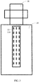
- FIG. 3 is a structural schematic diagram of an electrode side after the electrode and the tab of the battery are welded according to the first embodiment of the present application
- FIG. 4 is a structural schematic diagram of a tab side after the electrode and the tab of the battery cell are welded according to the first embodiment of the present application
- FIG. 5 is a microscopic view of the line-shaped welding mark formed after the electrode and the tab of the battery are welded according to the first embodiment of the present application.
- the present embodiment provides a battery, which includes a housing and a battery cell disposed in the housing, where the battery cell may be a wound battery cell or a laminated battery cell.
- the wound battery cell includes a positive electrode, a negative electrode and a separator separating the positive electrode from the negative electrode; a positive tab is welded on the positive electrode and a negative tab is welded on the negative electrode; in a winding process, the positive electrode, the separator and the negative electrode are wound in the same direction from the winding head and finally form a wound battery cell.
- the laminated battery cell includes a positive electrode, a negative electrode and a separator separating the positive electrode from the negative electrode; a positive tab is welded on the positive electrode and a negative tab is welded on the negative electrode; the positive electrode and the negative electrode are alternately stacked during the processing, and the separator is stacked between two adjacent positive electrode and negative electrode, and finally stacked to form a laminated battery.
- the battery cell includes electrodes 20 and tabs 30, and each of the electrodes 20 is integrally connected with a tab 30.
- the electrode 20 includes a current collector and an active material layer
- the current collector includes a coating zone coated with the active material layer and an empty foil zone not coated with the active material layer and an end of the tab 30 is welded to the empty foil zone of the electrode 20 by a laser welding process to connect the electrode 20 and the tab 30 together.
- the electrode may be either a positive electrode or a negative electrode.
- the electrode includes a current collector and an active material layer coated on the current collector surface. In order to weld the tab with the current collector, it is necessary to reserve an empty foil zone on the current collector surface which is not coated with the active material layer, or remove the active material layer in some area of the current collector surface to expose the current collector, where the exposed current collector surface is the empty foil zone, while the area covered with the active material layer is the coating zone.
- the current collector of positive electrode is aluminum foil
- the current collector of negative electrode is copper foil.
- laser welding is carried out on a surface of the empty foil zone facing away from the tab 30.
- a plurality of welding zones 21 arranged at intervals are formed on the surface of the empty foil zone facing away from the tab 30, and each of the welding zones 21 includes at least one line-shaped welding mark 211.
- the line-shaped welding mark 211 may be, for example, a straight welding mark, a curved welding mark, or a polyline welding mark. Generally, the number and the arrangement of the line-shaped welding mark 211 in each welding zone 21 are the same. In other implementations, the number and the arrangement of the line-shaped welding mark 211 in each welding zone 21 may also be set according to actual needs.
- the surface of the tab 30 facing away from the empty foil zone has no welding mark. Since laser welding is carried out from the surface of the empty foil zone facing away from the tab 30, the dot welding mark 211 is only formed on the surface of the empty foil zone facing away from the tab 30, while the surface of the tab 30 facing away from the empty foil zone maintains the original surface of the tab 30. That is to say, the original flatness of the surface of the tab 30 facing away from the empty foil zone will not be affected by welding, thus avoiding the formation of unfavorable structures on the surface of the tab 30 during welding.
- an end of the tab 30 and the empty foil zone of the electrode 20 are overlapped and attached.
- the empty foil zone of the electrode 20 may be tightly attached to the tab 30 by a hold-down fixture or an absorption fixture, so as to avoid the situation that the electrode 20 is welded through due to loose attachment.
- the laser welding device performs continuous welding on the tab 30 and the electrode 20 from the surface of the empty foil zone facing away from the tab 30 multiple times, and the continuous welding by the laser welding device may form a line-shaped welding mark 211, which may be, for example, a straight line-shaped welding mark, each time.
- each welding zone 21 includes at least one line-shaped welding mark 211, while there is no welding mark on the surface of the tab 30 facing away from the empty foil zone.
- the top of the line-shaped welding mark 211 may contact with the separator between the positive electrode and negative electrode.
- the contact area between the line-shaped welding mark 211 and the separator is larger than that between the needle-shaped welding protrusion and the separator in the prior art, the pressure between the line-shaped welding mark 211 and the separator is lower, and thus the line-shaped welding mark 211 is less likely to pierce the separator between the positive electrode and the negative electrode.
- the battery in the present embodiment includes a housing and a battery cell disposed in the housing, where the battery cell includes electrodes 20 and tabs 30, and each of the electrodes 20 is integrally connected with a tab 30; each of the electrode 20 includes a current collector and an active material layer, the current collector includes a coating zone coated with the active material layer and an empty foil zone not coated with the active material layer, and an end of the tab 30 is welded to the empty foil zone of the electrode 20 by a laser welding process, which could, on the one hand, avoid the occurrence of the phenomenon that the performance of the battery is influenced by pseudo welding or over welding caused by welding head wear during the ultrasonic welding, and on the other hand, save the work of replacing the welding head and thus reduce the workload of staffs.
- the surface of the empty foil zone of the electrode 20 facing away from the tab 30 may have a plurality of welding zones 21 arranged at intervals, each of which includes at least one line-shaped welding mark 211. Since the contact area between the line-shaped welding mark 211 and the separator is larger than that between the needle-shaped welding protrusion and the separator in the prior art, the pressure between the line-shaped welding mark 211 and the separator is lower, and thus the line-shaped welding mark 211 is less likely to pierce the separator between the positive electrode and the negative electrode, thereby preventing a short circuit between the positive electrode and the negative electrode and then being beneficial to the improvement of the quality and safety performance of the battery.
- the height of the line-shaped welding mark 211 is less than 30 ⁇ m.
- the height of the needle-shaped welding protrusion formed on the electrode side after the ultrasonic welding reaches more than 80 ⁇ m. It can be seen that the line-shaped welding mark 211 in the present embodiment has a smaller height, and is less likely to pierce the separator between the positive electrode and negative electrode, thereby preventing a short circuit between the positive electrode and negative electrode, and then being beneficial to the improvement of the quality and safety performance of the battery.
- the ratio of the height of the line-shaped welding mark 211 to the width of the line-shaped welding mark 211 is usually necessary to set to be less than 1, that is, the height of the line-shaped welding mark 211 is less than the width of the line-shaped welding mark 211.
- the height of the line-shaped welding mark 211 is relatively low, so that the probability that the line-shaped welding mark 211 pierces the separator between the positive electrode and the negative electrode is relatively low, thereby being beneficial to the improvement of the quality and safety performance of the battery;
- the width of the line-shaped welding mark 211 is relatively wide, which is beneficial to ensuring that the welding strength between the electrode 20 and the tab 30 could meet the requirement.
- the width of the line-shaped welding mark 211 may be set to be larger than 50 ⁇ m, so that the effective area of the welding connection between the electrode 20 and the tab 30 is relatively large.
- welding strength between the electrode 20 and the tab 30 could meet a requirement, and on the other hand, efficiency of power transmission between the electrode 20 and the tab 30 could be improved.
- the width of the line-shaped welding mark 211 may be set to be less than or equal to 50 ⁇ m according to actual needs, as long as the requirement on the welding strength between the electrode 20 and the tab 30 of the present embodiment can be achieved, which are not repeated herein.
- the welding zone 21 on the surface of the empty foil zone of the electrode 20 may include at least two line-shaped welding marks 211.
- two line-shaped welding marks 211, three line-shaped welding marks 211 or more line-shaped welding marks 211 may be disposed within a welding zone 21 according to actual needs.
- At least two line-shaped welding marks 211 may be disposed parallel to each other, and a distance between two adjacent line-shaped welding marks 211 is larger than 50 ⁇ m.
- a space between two adjacent line-shaped welding marks 211 is too narrow, heat dissipation is poor during welding, thus resulting in heat accumulation and further, oxidation and blackening or even perforation of the electrode, which affects the welding effect between the electrode 20 and the tab 30, and is not beneficial to the quality and safety performance of the battery.
- At least two line-shaped welding marks 211 may be disposed to cross with each other, for example, two straight welding marks may cross to form a cross-shaped welding mark according to actual needs; or, a plurality of straight welding marks may be crossed to form a " " shape according to actual needs; or, two curved welding marks may be crossed and disposed into any shape according to actual needs; or, the straight welding mark and the curved welding mark may be crossed with each other and disposed in any shape according to actual needs.
- the arrangement of the at least two line-shaped welding mark 211 in the welding zone 21 includes but is not limited to the above two arrangements, and other arrangements may be set according to actual needs during the specific implementation, which will not be repeated herein.
- a plurality of welding zones 21 may be arranged in an array on the side of the electrode 20.
- the number of rows and columns of the welding zones 21 can be set according to actual needs, as long as the electrode 20 and the tab 30 can be welded firmly to ensure a good power transmission effect between the electrode 20 and the tab 30, which is not particularly limited herein.
- the arrangement of the plurality of welding zones 21 on the side of the electrode 20 may also be adjusted according to actual needs, as long as the requirements of this embodiment can be met, which will not be repeated herein.
- a minimum distance between the line-shaped welding mark 211 and the coating zone is set to be larger than 1 mm in the present embodiment, so as to avoid accidentally damaging the active material layer of the electrode 20 during the welding process, which is further beneficial to ensuring that the quality of the battery is not affected.
- the empty foil zone is located at the head or tail of the current collector of the electrode.
- the tab 30 is welded with the empty foil zone of the electrode 20
- the tab 30 is located at the head or tail of the electrode 20.
- the empty foil zone of the electrode 20 may also be set in the middle of the electrode 20, and part of the active material layer in the middle of the electrode 20 may be removed to form the empty foil zone.
- the empty foil zone may be disposed at the middle position of the electrode of the wound battery cell along a length direction.
- the empty foil zone may extend outward from the middle position of the electrode of the laminated battery cell.
- the line-shaped welding mark 211 is only formed on the side of the electrode 20, and the original surface of the tab 30 is maintained on the side of the tab 30, that is, the original flatness of the surface of the tab 30 facing away from the electrode 20 may not be affected by welding, thereby being beneficial to avoiding that the surface of the tab 30 forms an unfavorable structure to the separator during the welding process.
- the present embodiment also provides a method for manufacturing a battery, where the battery includes a housing and a battery cell, and the battery cell includes electrodes and tabs, and the method includes: for each pair of an electrode and a tab, overlapping an end of the tab with an empty foil zone of the electrode; performing, by using a laser welding device, continuous welding on a surface of the empty foil zone facing away from the tab multiple times, where a line-shaped welding mark is formed by the continuous welding of the laser welding each time, a plurality of line-shaped welding marks are located in a plurality of welding zones arranged at intervals, so that each of the welding zones includes at least one line-shaped welding mark; the surface of the tab facing away from the empty foil zone having no welding mark; processing the electrode welded with the tab and a separator together to form the battery cell; and assembling the battery cell into the housing to form the battery.
- the electrode of the battery cell includes a positive electrode and a negative electrode
- the tab includes a positive tab and a negative tab.
- the empty foil zone of the positive electrode may be attached to the positive tab, for example, the empty foil zone of the positive electrode may be tightly attached to the positive tab by a hold-down fixture or an absorption fixture; then, a parameter of the laser welding device is set, for example, it may be set that the time of continuous welding of the laser welding device does not exceed 0.2ms each time, etc., and the laser welding device is used to perform the continuous welding on the positive tab and the positive electrode from the side of the positive electrode multiple times, with the total welding time not exceeding 1s, so that a plurality of welding zones arranged at intervals are formed on the surface of the positive electrode, and each of the welding zones includes at least one line-shaped welding mark. Furthermore, the surface of the tab facing away from the empty foil zone has no welding mark.
- the empty foil zone of the negative electrode may be attached to the negative tab, and then the laser welding device may be used to perform the continuous welding on the negative tab and the negative electrode from the side of the negative electrode multiple times, with the total welding time not exceeding 1s, so that a plurality of welding zones arranged at intervals are formed on the surface of the negative electrode, and each of the welding zones includes at least one line-shaped welding mark. Furthermore, the surface of the tab facing away from the empty foil zone has no welding mark.
- a wound battery cell may be formed by winding, or a laminated battery cell may be formed by stacking.
- the above-mentioned wound battery cell or laminated battery cell is assembled into a housing to form a battery.
- measured welding tension between the positive electrode and the positive tab is greater than 25N
- measured welding tension between the negative electrode and the negative tab is greater than 8N
- the process of measuring the welding tension between the tab and the electrode by using a tension meter is as follows: firstly, using adhesive tape to stick the welding zone on the electrode side; then clamping the top of the tab with the upper part of the tension meter, clamping the bottom of the aluminum foil material with the lower part of the tension meter, adjusting the tension display mode to the peak mode, and resetting the tension meter to start the measurement: pressing the "up" button to pull in opposite directions apart at 180 degrees until the tab is separated from the electrode; finally, reading the value displayed by the tension meter and recording it, and meanwhile, taking down the tab and measuring the ratio of the area of the current collector of the electrode remaining on the tab to the total area of the welding zone.
- the embodiment provides a portable electrical device, which includes a battery.
- the portable electrical device in the present embodiment includes a mobile terminal, which may be, for example, a mobile phone, a notebook, a tablet computer, a POS machine, a vehicle-mounted computer, a wearable device, etc.
- a mobile terminal which may be, for example, a mobile phone, a notebook, a tablet computer, a POS machine, a vehicle-mounted computer, a wearable device, etc.
- the battery in the present embodiment has the same structure as the battery according to the first embodiment, and could bring the same or similar technical effects, which will not be repeated herein. For details, please refer to the description of the above embodiment.
- connection should be understood in a broad sense, for example, they may be a fixed connection or a detachable connection, or an integrated connection; they may be a mechanical connection or an electrical connection; they may be a direct interconnection, or an indirect interconnection through an intermediate medium, and they may be an internal communication between two elements.
- installation e.g., they may be a fixed connection or a detachable connection, or an integrated connection; they may be a mechanical connection or an electrical connection; they may be a direct interconnection, or an indirect interconnection through an intermediate medium, and they may be an internal communication between two elements.
Landscapes
- Engineering & Computer Science (AREA)
- Chemical & Material Sciences (AREA)
- Chemical Kinetics & Catalysis (AREA)
- Electrochemistry (AREA)
- General Chemical & Material Sciences (AREA)
- Physics & Mathematics (AREA)
- Optics & Photonics (AREA)
- Manufacturing & Machinery (AREA)
- Plasma & Fusion (AREA)
- Mechanical Engineering (AREA)
- Materials Engineering (AREA)
- Connection Of Batteries Or Terminals (AREA)
Applications Claiming Priority (1)
| Application Number | Priority Date | Filing Date | Title |
|---|---|---|---|
| CN202010567298.XA CN111682155A (zh) | 2020-06-19 | 2020-06-19 | 电池及可移动用电设备 |
Publications (3)
| Publication Number | Publication Date |
|---|---|
| EP3926752A1 true EP3926752A1 (de) | 2021-12-22 |
| EP3926752B1 EP3926752B1 (de) | 2025-02-19 |
| EP3926752C0 EP3926752C0 (de) | 2025-02-19 |
Family
ID=72455887
Family Applications (1)
| Application Number | Title | Priority Date | Filing Date |
|---|---|---|---|
| EP20199282.3A Active EP3926752B1 (de) | 2020-06-19 | 2020-09-30 | Batterie und tragbare elektrische vorrichtung |
Country Status (3)
| Country | Link |
|---|---|
| US (2) | US11824227B2 (de) |
| EP (1) | EP3926752B1 (de) |
| CN (1) | CN111682155A (de) |
Families Citing this family (9)
| Publication number | Priority date | Publication date | Assignee | Title |
|---|---|---|---|---|
| CN111682155A (zh) * | 2020-06-19 | 2020-09-18 | 珠海冠宇电池股份有限公司 | 电池及可移动用电设备 |
| CN112658489B (zh) * | 2020-12-29 | 2022-05-13 | 比亚迪股份有限公司 | 清除极片活性物质的方法 |
| CN113422162A (zh) * | 2021-07-14 | 2021-09-21 | 厦门海辰新能源科技有限公司 | 集流体组件、电池单体和电池包 |
| CN113964327A (zh) * | 2021-11-18 | 2022-01-21 | 珠海冠宇电池股份有限公司 | 极片和电池 |
| CN114824672B (zh) * | 2022-03-30 | 2024-07-16 | 北京海博思创科技股份有限公司 | 电池模组的制备方法及电池模组 |
| US20250007125A1 (en) * | 2023-06-28 | 2025-01-02 | GM Global Technology Operations LLC | Joining of external tabs of electrodes of battery cells to terminals using pulsed laser |
| CN117293259A (zh) * | 2023-10-23 | 2023-12-26 | 宁德新能源科技有限公司 | 极片、电芯及用电设备 |
| CN117253961A (zh) * | 2023-10-23 | 2023-12-19 | 宁德新能源科技有限公司 | 极片、电芯及用电设备 |
| CN221961028U (zh) * | 2023-12-18 | 2024-11-05 | 珠海冠宇电池股份有限公司 | 电池 |
Citations (6)
| Publication number | Priority date | Publication date | Assignee | Title |
|---|---|---|---|---|
| US20090223940A1 (en) * | 2004-08-09 | 2009-09-10 | Nec Corporation | Different metallic thin plates welding method, bimetallic thin plates jointing element, electric device, and electric device assembly |
| DE102013015710A1 (de) * | 2013-09-20 | 2014-07-24 | Daimler Ag | Verfahren zur Herstellung einer flächigen Schweißverbindung und Anordnung mit einer flächigen Schweißverbindung |
| US20160114429A1 (en) * | 2014-04-15 | 2016-04-28 | Panasonic Intellectual Property Management Co., Ltd. | Dissimilar metal joined body |
| US20180358608A1 (en) * | 2016-02-29 | 2018-12-13 | Panasonic Intellectual Property Management Co., Ltd. | Method for producing electrode assembly and method for producing nonaqueous electrolyte secondary battery |
| CN209822770U (zh) * | 2019-05-21 | 2019-12-20 | 宁德新能源科技有限公司 | 极片及具有所述极片的电池 |
| EP3648199A1 (de) * | 2017-06-27 | 2020-05-06 | LG Chem, Ltd. | Verfahren zum schweissen einer elektrodenlasche und kabel-sekundärbatterie mit einer so hergestellten elektrode |
Family Cites Families (14)
| Publication number | Priority date | Publication date | Assignee | Title |
|---|---|---|---|---|
| US8803024B2 (en) * | 2007-12-12 | 2014-08-12 | GM Global Technology Operations LLC | Online weld inspection and repair method for resistance welding and weld-bonding |
| CN202094205U (zh) * | 2011-05-26 | 2011-12-28 | 东莞市利赛奥新能源科技有限公司 | 一种软包装锂离子电池极耳与镍带的连接机构 |
| CN203481318U (zh) * | 2013-06-06 | 2014-03-12 | 珠海银隆新能源有限公司 | 电池极片及高功率电池 |
| CN105990612A (zh) * | 2015-02-05 | 2016-10-05 | 宁德新能源科技有限公司 | 电芯 |
| CN106328984B (zh) * | 2015-06-15 | 2019-05-28 | 河南比得力高新能源科技有限公司 | 防震圆柱型动力锂离子电池及其制备工艺 |
| US10476048B2 (en) * | 2016-03-17 | 2019-11-12 | Contemporary Amperex Technology Co., Limited | Secondary battery |
| CN105591062B (zh) * | 2016-03-17 | 2018-08-24 | 宁德时代新能源科技股份有限公司 | 二次电池 |
| JP6909406B2 (ja) * | 2017-12-05 | 2021-07-28 | トヨタ自動車株式会社 | 電池モジュール |
| CN207868261U (zh) * | 2017-12-22 | 2018-09-14 | 惠州亿纬锂能股份有限公司 | 一种锂离子电池 |
| JP7009271B2 (ja) * | 2018-03-16 | 2022-01-25 | 三洋電機株式会社 | 密閉電池の製造方法及び密閉電池 |
| US10919112B2 (en) * | 2018-04-30 | 2021-02-16 | GM Global Technology Operations LLC | Method and system for manufacturing a lithium metal negative electrode |
| EP4040551A4 (de) * | 2019-09-26 | 2024-06-19 | Guangdong Mic-power New Energy Co., Ltd. | Elektrodenkissen für einen batterierollenkern und zylinder- oder knopfbatterie |
| KR102622753B1 (ko) * | 2020-02-17 | 2024-01-10 | 삼성에스디아이 주식회사 | 이차전지용 레이저 용접 방법 및 모니터링 방법 |
| CN111682155A (zh) * | 2020-06-19 | 2020-09-18 | 珠海冠宇电池股份有限公司 | 电池及可移动用电设备 |
-
2020
- 2020-06-19 CN CN202010567298.XA patent/CN111682155A/zh active Pending
- 2020-09-22 US US17/028,344 patent/US11824227B2/en active Active
- 2020-09-30 EP EP20199282.3A patent/EP3926752B1/de active Active
-
2023
- 2023-11-16 US US18/510,772 patent/US12341221B2/en active Active
Patent Citations (6)
| Publication number | Priority date | Publication date | Assignee | Title |
|---|---|---|---|---|
| US20090223940A1 (en) * | 2004-08-09 | 2009-09-10 | Nec Corporation | Different metallic thin plates welding method, bimetallic thin plates jointing element, electric device, and electric device assembly |
| DE102013015710A1 (de) * | 2013-09-20 | 2014-07-24 | Daimler Ag | Verfahren zur Herstellung einer flächigen Schweißverbindung und Anordnung mit einer flächigen Schweißverbindung |
| US20160114429A1 (en) * | 2014-04-15 | 2016-04-28 | Panasonic Intellectual Property Management Co., Ltd. | Dissimilar metal joined body |
| US20180358608A1 (en) * | 2016-02-29 | 2018-12-13 | Panasonic Intellectual Property Management Co., Ltd. | Method for producing electrode assembly and method for producing nonaqueous electrolyte secondary battery |
| EP3648199A1 (de) * | 2017-06-27 | 2020-05-06 | LG Chem, Ltd. | Verfahren zum schweissen einer elektrodenlasche und kabel-sekundärbatterie mit einer so hergestellten elektrode |
| CN209822770U (zh) * | 2019-05-21 | 2019-12-20 | 宁德新能源科技有限公司 | 极片及具有所述极片的电池 |
Non-Patent Citations (2)
| Title |
|---|
| ABHISHEK DAS ET AL: "Joining Technologies for Automotive Battery Systems Manufacturing", WORLD ELECTRIC VEHICLE JOURNAL, vol. 9, no. 2, 5 July 2018 (2018-07-05), pages 22, XP055725546, DOI: 10.3390/wevj9020022 * |
| MESKO JOZEF ET AL: "Microstructure Analysis of Welded Joints after Laser Welding", MANUFACTURING TECHNOLOGY : JOURNAL FOR SCIENCE, RESEARCH AND PRODUCTION, vol. 14, no. 3, 1 October 2014 (2014-10-01), Usti nad Labemcze, pages 355 - 359, XP055781530, ISSN: 1213-2489, Retrieved from the Internet <URL:https://ieeexplore.ieee.org/iel5/4636107/4649055/04649887.pdf?casa_token=65TwMm3J3c8AAAAA:kb6Jq0ZRyX6TbyLhiBidDKlznbGCwtXz9v-nvLdIA1fWGiHn8Vm8WiZ4Dbri01FDHGKqgfIPWqY> [retrieved on 20210303], DOI: 10.21062/ujep/x.2014/a/1213-2489/MT/14/3/355 * |
Also Published As
| Publication number | Publication date |
|---|---|
| US20210399270A1 (en) | 2021-12-23 |
| EP3926752B1 (de) | 2025-02-19 |
| CN111682155A (zh) | 2020-09-18 |
| US20240088527A1 (en) | 2024-03-14 |
| EP3926752C0 (de) | 2025-02-19 |
| US12341221B2 (en) | 2025-06-24 |
| US11824227B2 (en) | 2023-11-21 |
Similar Documents
| Publication | Publication Date | Title |
|---|---|---|
| US12341221B2 (en) | Battery and portable electrical device | |
| US11450932B2 (en) | Battery, preparation method thereof and electric device | |
| CN108598491B (zh) | 二次电池及其极片 | |
| US20240222817A1 (en) | Battery, manufacturing method thereof and electronic product | |
| EP4333099A1 (de) | Batterieelektrodenplatte, batterie und verfahren zur herstellung einer batterieelektrodenplatte | |
| WO2023088433A1 (zh) | 极片和电池 | |
| JP2014022116A (ja) | 二次電池用極板及び二次電池用極板の製造方法 | |
| CN111682153B (zh) | 极耳焊接结构、电池及电子产品 | |
| EP3731297A1 (de) | Batteriemodul, sekundärbatterie und kappenanordnung dafür | |
| CN108963175A (zh) | 电池的极片结构、电池卷芯和电池卷芯的制作方法 | |
| US20240347785A1 (en) | Electrode core, battery apparatus, and electronic device | |
| EP4631664A1 (de) | Ultraschallschweissvorrichtung und schweissstruktur | |
| CN113661605B (zh) | 电化学装置和电子装置 | |
| CN209401736U (zh) | 电极构件、电极组件及二次电池 | |
| CN114300651B (zh) | 一种极片及电池 | |
| JP3338638B2 (ja) | 有機電解液電池 | |
| JP2016170888A (ja) | 扁平型電池 | |
| CN223092919U (zh) | 锂离子电池 | |
| US20240136671A1 (en) | Electrode plate and battery | |
| CN220544194U (zh) | 单体电池和电池组 | |
| CN217903145U (zh) | 一种极片和电池 | |
| WO2026026879A1 (zh) | 电芯 | |
| WO2025139201A1 (zh) | 一种电极极片及电芯 | |
| JP2025531530A (ja) | 電気化学装置および電力消費機器 | |
| JP2020167135A (ja) | 電気化学デバイス |
Legal Events
| Date | Code | Title | Description |
|---|---|---|---|
| PUAI | Public reference made under article 153(3) epc to a published international application that has entered the european phase |
Free format text: ORIGINAL CODE: 0009012 |
|
| STAA | Information on the status of an ep patent application or granted ep patent |
Free format text: STATUS: REQUEST FOR EXAMINATION WAS MADE |
|
| 17P | Request for examination filed |
Effective date: 20200930 |
|
| AK | Designated contracting states |
Kind code of ref document: A1 Designated state(s): AL AT BE BG CH CY CZ DE DK EE ES FI FR GB GR HR HU IE IS IT LI LT LU LV MC MK MT NL NO PL PT RO RS SE SI SK SM TR |
|
| B565 | Issuance of search results under rule 164(2) epc |
Effective date: 20210317 |
|
| RIC1 | Information provided on ipc code assigned before grant |
Ipc: B23K 26/244 20140101ALI20240320BHEP Ipc: B23K 26/26 20140101ALI20240320BHEP Ipc: B23K 103/18 20060101ALI20240320BHEP Ipc: B23K 103/12 20060101ALI20240320BHEP Ipc: B23K 103/10 20060101ALI20240320BHEP Ipc: B23K 101/38 20060101ALI20240320BHEP Ipc: B23K 101/36 20060101ALI20240320BHEP Ipc: B23K 11/11 20060101ALI20240320BHEP Ipc: B23K 26/22 20060101ALI20240320BHEP Ipc: H01M 4/13 20100101ALI20240320BHEP Ipc: H01M 50/566 20210101ALI20240320BHEP Ipc: H01M 50/536 20210101ALI20240320BHEP Ipc: H01M 50/531 20210101AFI20240320BHEP |
|
| GRAP | Despatch of communication of intention to grant a patent |
Free format text: ORIGINAL CODE: EPIDOSNIGR1 |
|
| STAA | Information on the status of an ep patent application or granted ep patent |
Free format text: STATUS: GRANT OF PATENT IS INTENDED |
|
| INTG | Intention to grant announced |
Effective date: 20240515 |
|
| GRAJ | Information related to disapproval of communication of intention to grant by the applicant or resumption of examination proceedings by the epo deleted |
Free format text: ORIGINAL CODE: EPIDOSDIGR1 |
|
| STAA | Information on the status of an ep patent application or granted ep patent |
Free format text: STATUS: REQUEST FOR EXAMINATION WAS MADE |
|
| GRAP | Despatch of communication of intention to grant a patent |
Free format text: ORIGINAL CODE: EPIDOSNIGR1 |
|
| STAA | Information on the status of an ep patent application or granted ep patent |
Free format text: STATUS: GRANT OF PATENT IS INTENDED |
|
| INTC | Intention to grant announced (deleted) | ||
| INTG | Intention to grant announced |
Effective date: 20240913 |
|
| GRAS | Grant fee paid |
Free format text: ORIGINAL CODE: EPIDOSNIGR3 |
|
| GRAA | (expected) grant |
Free format text: ORIGINAL CODE: 0009210 |
|
| STAA | Information on the status of an ep patent application or granted ep patent |
Free format text: STATUS: THE PATENT HAS BEEN GRANTED |
|
| AK | Designated contracting states |
Kind code of ref document: B1 Designated state(s): AL AT BE BG CH CY CZ DE DK EE ES FI FR GB GR HR HU IE IS IT LI LT LU LV MC MK MT NL NO PL PT RO RS SE SI SK SM TR |
|
| REG | Reference to a national code |
Ref country code: GB Ref legal event code: FG4D |
|
| REG | Reference to a national code |
Ref country code: CH Ref legal event code: EP |
|
| REG | Reference to a national code |
Ref country code: DE Ref legal event code: R096 Ref document number: 602020046227 Country of ref document: DE |
|
| REG | Reference to a national code |
Ref country code: IE Ref legal event code: FG4D |
|
| U01 | Request for unitary effect filed |
Effective date: 20250314 |
|
| U07 | Unitary effect registered |
Designated state(s): AT BE BG DE DK EE FI FR IT LT LU LV MT NL PT RO SE SI Effective date: 20250321 |
|
| PG25 | Lapsed in a contracting state [announced via postgrant information from national office to epo] |
Ref country code: RS Free format text: LAPSE BECAUSE OF FAILURE TO SUBMIT A TRANSLATION OF THE DESCRIPTION OR TO PAY THE FEE WITHIN THE PRESCRIBED TIME-LIMIT Effective date: 20250519 |
|
| PG25 | Lapsed in a contracting state [announced via postgrant information from national office to epo] |
Ref country code: PL Free format text: LAPSE BECAUSE OF FAILURE TO SUBMIT A TRANSLATION OF THE DESCRIPTION OR TO PAY THE FEE WITHIN THE PRESCRIBED TIME-LIMIT Effective date: 20250219 |
|
| PG25 | Lapsed in a contracting state [announced via postgrant information from national office to epo] |
Ref country code: ES Free format text: LAPSE BECAUSE OF FAILURE TO SUBMIT A TRANSLATION OF THE DESCRIPTION OR TO PAY THE FEE WITHIN THE PRESCRIBED TIME-LIMIT Effective date: 20250219 |
|
| PG25 | Lapsed in a contracting state [announced via postgrant information from national office to epo] |
Ref country code: IS Free format text: LAPSE BECAUSE OF FAILURE TO SUBMIT A TRANSLATION OF THE DESCRIPTION OR TO PAY THE FEE WITHIN THE PRESCRIBED TIME-LIMIT Effective date: 20250619 Ref country code: NO Free format text: LAPSE BECAUSE OF FAILURE TO SUBMIT A TRANSLATION OF THE DESCRIPTION OR TO PAY THE FEE WITHIN THE PRESCRIBED TIME-LIMIT Effective date: 20250519 |
|
| PG25 | Lapsed in a contracting state [announced via postgrant information from national office to epo] |
Ref country code: HR Free format text: LAPSE BECAUSE OF FAILURE TO SUBMIT A TRANSLATION OF THE DESCRIPTION OR TO PAY THE FEE WITHIN THE PRESCRIBED TIME-LIMIT Effective date: 20250219 |
|
| PG25 | Lapsed in a contracting state [announced via postgrant information from national office to epo] |
Ref country code: GR Free format text: LAPSE BECAUSE OF FAILURE TO SUBMIT A TRANSLATION OF THE DESCRIPTION OR TO PAY THE FEE WITHIN THE PRESCRIBED TIME-LIMIT Effective date: 20250520 |
|
| PG25 | Lapsed in a contracting state [announced via postgrant information from national office to epo] |
Ref country code: SM Free format text: LAPSE BECAUSE OF FAILURE TO SUBMIT A TRANSLATION OF THE DESCRIPTION OR TO PAY THE FEE WITHIN THE PRESCRIBED TIME-LIMIT Effective date: 20250219 |
|
| U20 | Renewal fee for the european patent with unitary effect paid |
Year of fee payment: 6 Effective date: 20250909 |
|
| PGFP | Annual fee paid to national office [announced via postgrant information from national office to epo] |
Ref country code: GB Payment date: 20250828 Year of fee payment: 6 |
|
| PG25 | Lapsed in a contracting state [announced via postgrant information from national office to epo] |
Ref country code: CZ Free format text: LAPSE BECAUSE OF FAILURE TO SUBMIT A TRANSLATION OF THE DESCRIPTION OR TO PAY THE FEE WITHIN THE PRESCRIBED TIME-LIMIT Effective date: 20250219 |
|
| PG25 | Lapsed in a contracting state [announced via postgrant information from national office to epo] |
Ref country code: SK Free format text: LAPSE BECAUSE OF FAILURE TO SUBMIT A TRANSLATION OF THE DESCRIPTION OR TO PAY THE FEE WITHIN THE PRESCRIBED TIME-LIMIT Effective date: 20250219 |
|
| PLBE | No opposition filed within time limit |
Free format text: ORIGINAL CODE: 0009261 |
|
| STAA | Information on the status of an ep patent application or granted ep patent |
Free format text: STATUS: NO OPPOSITION FILED WITHIN TIME LIMIT |
|
| 26N | No opposition filed |
Effective date: 20251120 |