EP3926823B1 - Parametrisches kurvenabtastverfahren, fotovoltaik-string, wandler und fotovoltaisches energieerzeugungssystem - Google Patents
Parametrisches kurvenabtastverfahren, fotovoltaik-string, wandler und fotovoltaisches energieerzeugungssystem Download PDFInfo
- Publication number
- EP3926823B1 EP3926823B1 EP20922468.2A EP20922468A EP3926823B1 EP 3926823 B1 EP3926823 B1 EP 3926823B1 EP 20922468 A EP20922468 A EP 20922468A EP 3926823 B1 EP3926823 B1 EP 3926823B1
- Authority
- EP
- European Patent Office
- Prior art keywords
- voltage
- endpoint
- parametric curve
- curve
- photovoltaic string
- Prior art date
- Legal status (The legal status is an assumption and is not a legal conclusion. Google has not performed a legal analysis and makes no representation as to the accuracy of the status listed.)
- Active
Links
Images



Classifications
-
- H—ELECTRICITY
- H02—GENERATION; CONVERSION OR DISTRIBUTION OF ELECTRIC POWER
- H02J—ELECTRIC POWER NETWORKS; CIRCUIT ARRANGEMENTS OR SYSTEMS FOR SUPPLYING OR DISTRIBUTING ELECTRIC POWER; SYSTEMS FOR STORING ELECTRIC ENERGY
- H02J3/00—Circuit arrangements for AC mains or AC distribution networks
- H02J3/38—Arrangements for feeding a single network from two or more generators or sources in parallel; Arrangements for feeding already energised networks from additional generators or sources in parallel
- H02J3/381—Dispersed generators
-
- H—ELECTRICITY
- H02—GENERATION; CONVERSION OR DISTRIBUTION OF ELECTRIC POWER
- H02S—GENERATION OF ELECTRIC POWER BY CONVERSION OF INFRARED RADIATION, VISIBLE LIGHT OR ULTRAVIOLET LIGHT, e.g. USING PHOTOVOLTAIC [PV] MODULES
- H02S50/00—Monitoring or testing of PV systems, e.g. load balancing or fault identification
- H02S50/10—Testing of PV devices, e.g. of PV modules or single PV cells
-
- H—ELECTRICITY
- H02—GENERATION; CONVERSION OR DISTRIBUTION OF ELECTRIC POWER
- H02J—ELECTRIC POWER NETWORKS; CIRCUIT ARRANGEMENTS OR SYSTEMS FOR SUPPLYING OR DISTRIBUTING ELECTRIC POWER; SYSTEMS FOR STORING ELECTRIC ENERGY
- H02J2101/00—Supply or distribution of decentralised, dispersed or local electric power generation
- H02J2101/20—Dispersed power generation using renewable energy sources
- H02J2101/22—Solar energy
- H02J2101/24—Photovoltaics
-
- H—ELECTRICITY
- H02—GENERATION; CONVERSION OR DISTRIBUTION OF ELECTRIC POWER
- H02J—ELECTRIC POWER NETWORKS; CIRCUIT ARRANGEMENTS OR SYSTEMS FOR SUPPLYING OR DISTRIBUTING ELECTRIC POWER; SYSTEMS FOR STORING ELECTRIC ENERGY
- H02J2101/00—Supply or distribution of decentralised, dispersed or local electric power generation
- H02J2101/20—Dispersed power generation using renewable energy sources
- H02J2101/22—Solar energy
- H02J2101/24—Photovoltaics
- H02J2101/25—Photovoltaics involving maximum power point tracking control for photovoltaic sources
-
- Y—GENERAL TAGGING OF NEW TECHNOLOGICAL DEVELOPMENTS; GENERAL TAGGING OF CROSS-SECTIONAL TECHNOLOGIES SPANNING OVER SEVERAL SECTIONS OF THE IPC; TECHNICAL SUBJECTS COVERED BY FORMER USPC CROSS-REFERENCE ART COLLECTIONS [XRACs] AND DIGESTS
- Y02—TECHNOLOGIES OR APPLICATIONS FOR MITIGATION OR ADAPTATION AGAINST CLIMATE CHANGE
- Y02E—REDUCTION OF GREENHOUSE GAS [GHG] EMISSIONS, RELATED TO ENERGY GENERATION, TRANSMISSION OR DISTRIBUTION
- Y02E10/00—Energy generation through renewable energy sources
- Y02E10/50—Photovoltaic [PV] energy
Definitions
- This application relates to the field of photovoltaic power generation technologies, and in particular, to a parametric curve scanning method for a photovoltaic string, a converter, and a photovoltaic power generation system.
- a photovoltaic power generation system is a power generation system in which solar energy is directly converted into electrical energy by using a photovoltaic module (Solar Cell Module), and includes a photovoltaic string, a battery, a controller, and a photovoltaic inverter.
- the photovoltaic string includes a plurality of photovoltaic modules that are combined in series or/and in parallel.
- the photovoltaic module is a smallest indivisible photovoltaic cell assembly that can independently provide a direct current output.
- a photovoltaic system may perform IV curve scanning on the photovoltaic string on line.
- IV curve scanning can also help the photovoltaic system to learn of information such as a current power generation capability and working condition of the photovoltaic string.
- a light change exerts relatively large impact on an IV output feature of the photovoltaic string. If there is a light change in a process in which the photovoltaic system performs IV curve scanning on the photovoltaic string, an IV curve that is of the photovoltaic string and that is obtained through detection cannot accurately reflect the IV output feature of the photovoltaic string.
- CN 110 677 118 A discloses an optimizer, a photovoltaic power generation system, and an IV curve scanning method for a photovoltaic module.
- the photovoltaic power generation system includes a plurality of photovoltaic modules, a plurality of optimizers, and an inverter. An input end of each optimizer is connected to at least one photovoltaic module, and output ends of the plurality of optimizers are connected in series to form a string and then connected to the inverter.
- the optimizer includes a conversion unit, and a control unit configured to control the conversion unit.
- the optimizer further includes an auxiliary power source, an energy storage unit, and a first unidirectional conduction unit that are connected between the conversion unit and the control unit.
- the control unit is configured to perform IV curve scanning for each voltage segment, where the voltage segments are obtained by segmenting a range of an output voltage of a photovoltaic module corresponding to the optimizer from an open-circuit voltage to a preset minimum voltage, and at least two voltage segments are obtained through division.
- costs and a volume of the optimizer can be reduced.
- US 2018/234051 A1 discloses an IV curve scan method for a photovoltaic module and an optimizer.
- the optimizer receives an IV curve scan signal and controls an output voltage of the photovoltaic module corresponding to the IV curve scan signal to change from an open-circuit voltage to a preset minimum voltage according to a preset rule, while photovoltaic module connected to another optimizer can still operate normally, so that the system can operate normally. Then the optimizer uploads IV curve data of the photovoltaic module corresponding to the IV curve scan signal, to complete an IV curve scan on a single photovoltaic module.
- Embodiments of this application disclose a parametric curve scanning method for a photovoltaic string, a converter, and a photovoltaic power generation system, so that whether the currently obtained parametric curve is affected by a light change can be determined based on the obtained parametric curve, to determine whether the currently obtained parametric curve is valid, thereby improving parametric curve scanning reliability.
- an embodiment of this application discloses a parametric curve scanning method for a photovoltaic string, including in particular: controlling an output voltage of the photovoltaic string to change from a first endpoint voltage of a first voltage range to a second endpoint voltage of the first voltage range according to a first preset rule, and obtaining a current parameter or a power parameter of the photovoltaic string in the process in which the output voltage of the photovoltaic string changes, to scan a first parametric curve; controlling the output voltage of the photovoltaic string to change from a third endpoint voltage of a second voltage range to a fourth endpoint voltage of the second voltage range according to a second preset rule, and obtaining a current parameter or a power parameter of the photovoltaic string in the process in which the output voltage of the photovoltaic string changes, to scan a second parametric curve, where there is an intersection set between the first voltage range and the second voltage range.
- the first voltage range is a voltage scanning range including a maximum output voltage and a minimum output voltage of the photovoltaic string in a process of scanning the first parametric curve.
- the second voltage range is a voltage scanning range including a maximum output voltage and a minimum output voltage of the photovoltaic string in a process of scanning the second parametric curve.
- the maximum output voltage of the photovoltaic string may be an open-circuit voltage, and a minimum output voltage value may be 0 V.
- parametric curve scanning is separately performed on the photovoltaic string in the first voltage range and the second voltage range, and there is an intersection set between the first voltage range and the second voltage range, so that the first parametric curve and the second parametric curve that are obtained include parts corresponding to a same voltage.
- currents corresponding to the same voltage are obtained at different time points, so that it can be determined, by comparing the currents corresponding to the same voltage part, whether the currently obtained parametric curve is affected by a light change, to further determine whether the currently obtained parametric curve is valid, thereby improving reliability of parametric curve scanning reliability.
- no test device needs to be additionally added, to effectively reduce a quantity of hardware devices that need to be provided, and reduce costs.
- the first endpoint voltage is greater than the second endpoint voltage and the third endpoint voltage is less than the fourth endpoint voltage; or the first endpoint voltage is less than the second endpoint voltage and the third endpoint voltage is greater than the fourth endpoint voltage.
- a scanning endpoint of the first parametric curve is relatively close to a scanning startpoint of the second parametric curve. Therefore, a parametric curve scanning speed can be increased.
- the first endpoint voltage is equal to the fourth endpoint voltage, and/or the second endpoint voltage is equal to the third endpoint voltage.
- data at two sampling points is completely the same, and a time-related waveform in the first voltage range is symmetrical to a time-related waveform in the second voltage range.
- the first preset rule is a rule in which a voltage drops by a fixed voltage difference and the second preset rule is a rule in which a voltage rises by a fixed voltage difference; or the first preset rule is a rule in which a voltage rises by a fixed voltage difference and the second preset rule is a rule in which a voltage drops by a fixed voltage difference.
- the scanning method further includes: determining, based on the first parametric curve and the second parametric curve, whether the currently scanned parametric curve is affected by a light change.
- the determining, based on the first parametric curve and the second parametric curve, whether the currently scanned parametric curve is affected by a light change includes: comparing the first parametric curve and the second parametric curve, to determine whether light intensity corresponding to the first parametric curve and light intensity corresponding to the second parametric curve change.
- the scanning method further includes: processing the first parametric curve and the second parametric curve when it is determined that the currently scanned curve is not affected by the light change, to obtain a final parametric curve.
- an abnormal signal is sent when it is determined that the currently scanned curve is affected by the light change, to report, to a host computer, that current scanning fails. Therefore, the host computer may determine, based on feedback, whether to send a parametric curve scanning instruction again.
- an embodiment of this application discloses a converter, including an adjustment unit and an obtaining unit.
- the adjustment unit is configured to control an output voltage of the photovoltaic string to change from a first endpoint voltage of a first voltage range to a second endpoint voltage of the first voltage range according to a first preset rule.
- the obtaining unit is configured to obtain a current parameter and/or a power parameter of the photovoltaic string in the process in which the output voltage of the photovoltaic string changes, to scan a first parametric curve.
- the adjustment unit is further configured to control the output voltage of the photovoltaic string to change from a third endpoint voltage of a second voltage range to a fourth endpoint voltage of the second voltage range according to a second preset rule.
- the obtaining unit is further configured to obtain a current parameter and/or a power parameter of the photovoltaic string in the process in which the output voltage of the photovoltaic string changes, to scan a second parametric curve. There is an intersection set between the first voltage range and the second voltage range.
- a voltage parameter is also obtained when the current parameter and/or the power parameter of the photovoltaic string is obtained in the process in which the output voltage of the photovoltaic string changes, to form a current-voltage (IV) curve or a power-voltage (PV) curve.
- the first voltage range is a first voltage scanning range including a maximum output voltage and a minimum output voltage of the photovoltaic string in a process of scanning the first parametric curve.
- the second voltage range is a second voltage scanning range including a maximum output voltage and a minimum output voltage of the photovoltaic string in a process of scanning the second parametric curve.
- the maximum output voltage of the photovoltaic string may be an open-circuit voltage, and a minimum output voltage value may be 0 V.
- the first endpoint voltage is greater than the second endpoint voltage and the third endpoint voltage is less than the fourth endpoint voltage; or the first endpoint voltage is less than the second endpoint voltage and the third endpoint voltage is greater than the fourth endpoint voltage.
- the first endpoint voltage is equal to the fourth endpoint voltage, and/or the second endpoint voltage is equal to the third endpoint voltage.
- a time-related waveform in the first voltage range is symmetrical to a time-related waveform in the second voltage range.
- the first preset rule is a rule in which a voltage drops by a fixed voltage difference and the second preset rule is a rule in which a voltage rises by a fixed voltage difference; or the first preset rule is a rule in which a voltage rises by a fixed voltage difference and the second preset rule is a rule in which a voltage drops by a fixed voltage difference.
- the converter further includes a determining unit.
- the determining unit is configured to determine, based on the first parametric curve and the second parametric curve, whether the currently scanned parametric curve is affected by a light change.
- the determining unit is configured to compare the first parametric curve and the second parametric curve, to determine whether light intensity corresponding to the first parametric curve and light intensity corresponding to the second parametric curve change.
- the determining unit is configured to: when an absolute value of a difference between the corresponding parameter values of a same voltage point that are on the first parametric curve and the second parametric curve is less than a preset threshold, determine that the currently scanned parametric curve is not affected by the light change.
- the converter further includes a processing unit.
- the processing unit is configured to process the first parametric curve and the second parametric curve when it is determined that the currently scanned curve is not affected by the light change, to obtain a final parametric curve.
- the processing unit is further configured to send an abnormal signal when it is determined that the currently scanned curve is affected by the light change.
- an embodiment of this application discloses a converter, in particular including a DC/DC circuit and a sampling circuit.
- the sampling circuit and the DC/DC circuit are electrically connected.
- the DC/DC circuit is configured to control an output voltage of the photovoltaic string to change from a first endpoint voltage of a first voltage range to a second endpoint voltage of the first voltage range according to a first preset rule.
- the sampling circuit is configured to obtain a current parameter and/or a power parameter of the photovoltaic string in the process in which the output voltage of the photovoltaic string changes, to scan a first parametric curve.
- the DC/DC circuit is further configured to control the output voltage of the photovoltaic string to change from a third endpoint voltage of a second voltage range to a fourth endpoint voltage of the second voltage range according to a second preset rule.
- the sampling circuit is further configured to obtain a current parameter and/or a power parameter of the photovoltaic string in the process in which the output voltage of the photovoltaic string changes, to scan a second parametric curve. There is an intersection set between the first voltage range and the second voltage range.
- the first voltage range is a first voltage scanning range including a maximum output voltage and a minimum output voltage of the photovoltaic string in a process of scanning the first parametric curve.
- the second voltage range is a second voltage scanning range including a maximum output voltage and a minimum output voltage of the photovoltaic string in a process of scanning the second parametric curve.
- the maximum output voltage of the photovoltaic string may be an open-circuit voltage, and a minimum output voltage value may be 0 V.
- the first endpoint voltage is greater than the second endpoint voltage and the third endpoint voltage is less than the fourth endpoint voltage; or the first endpoint voltage is less than the second endpoint voltage and the third endpoint voltage is greater than the fourth endpoint voltage.
- the first endpoint voltage is equal to the fourth endpoint voltage, and/or the second endpoint voltage is equal to the third endpoint voltage.
- a time-related waveform in the first voltage range is symmetrical to a time-related waveform in the second voltage range.
- the first preset rule is a rule in which a voltage drops by a fixed voltage difference and the second preset rule is a rule in which a voltage rises by a fixed voltage difference; or the first preset rule is a rule in which a voltage rises by a fixed voltage difference and the second preset rule is a rule in which a voltage drops by a fixed voltage difference.
- the converter further includes a controller, and the controller is separately electrically connected to the DC/DC circuit and the sampling circuit.
- the controller is configured to determine, based on the first parametric curve and the second parametric curve, whether the currently scanned parametric curve is affected by a light change.
- the controller is configured to compare the first parametric curve and the second parametric curve, to determine whether light intensity corresponding to the first parametric curve and light intensity corresponding to the second parametric curve change.
- the controller is configured to: when an absolute value of a difference between the corresponding parameter values of a same voltage point that are on the first parametric curve and the second parametric curve is less than a preset threshold, determine that the currently scanned parametric curve is not affected by the light change.
- the controller is further configured to process the first parametric curve and the second parametric curve when it is determined that the currently scanned curve is not affected by the light change, to obtain a final parametric curve.
- the controller is further configured to send an abnormal signal when it is determined that the currently scanned curve is affected by the light change.
- an embodiment of this application discloses a photovoltaic power generation system, including a power grid and at least one photovoltaic string.
- the photovoltaic power generation system further includes the converter according to any one of the second aspect and the possible implementations of the second aspect; or the photovoltaic power generation system further includes the converter according to any one of the third aspect and the possible implementations of the third aspect.
- An input end of the converter is connected to the at least one photovoltaic string, and an output end of the converter is connected to the power grid.
- an embodiment of this application discloses a computer-readable storage medium.
- the computer-readable storage medium stores a computer program, the computer program includes at least one segment of code, and the at least one segment of code may be executed by a computer, to control the computer to perform the method according to any one of the first aspect and the possible implementations of the first aspect.
- This application provides a photovoltaic power generation system, a converter applied to the photovoltaic power generation system, and a parametric curve scanning method for a photovoltaic string.
- the parametric curve includes a current-voltage (Current Voltage, IV) curve or a power-voltage (Power Voltage, PV) curve.
- the converter may perform parametric curve scanning on at least one photovoltaic string connected to the converter, to detect whether the photovoltaic string is defective or damaged, and learn of a power generation capability of the current photovoltaic power generation system by using a scanned parametric curve.
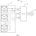
- FIG. 1 is a schematic structural diagram of a photovoltaic power generation system 1000 according to an embodiment of this application.
- the photovoltaic power generation system 1000 includes a converter 100, at least one photovoltaic string 300, and a power grid 500.
- the photovoltaic string 300 includes a plurality of photovoltaic modules 301 that are combined in series or/and in parallel.
- the photovoltaic module 301 also referred to as a solar panel, is a core part of the photovoltaic power generation system, converts solar energy into electrical energy to provide a direct current output, and transmits the electrical energy to a battery for storage or to drive a load to work.
- a and/or B in this application means A and B, and A or B.
- the photovoltaic string 300 may include only one photovoltaic module 301.
- the converter 100 is connected to at least one photovoltaic string 300, to convert output power of the photovoltaic module 300 connected to the converter 100.
- the converter 100 is a photovoltaic inverter, and may be further configured to: convert, into an alternating current, a direct current output by the at least one photovoltaic string 300, and then output the alternating current to the power grid 500.
- the converter 100 may be an optimizer.
- the converter 100 is not limited herein, provided that the converter 100 can convert the output power of the photovoltaic module 300 connected to the converter 100.
- the power grid 500 also referred to as an electrical grid, includes a substation for various voltages and a power transmission and distribution line in a power system (that is, includes a voltage transformation unit, a power transmission unit, and a power distribution unit), and is configured to: transmit and distribute electrical energy, and change a voltage.
- the photovoltaic power generation system 1000 may include a plurality of converters 100, and an alternating current side of the converter 100 may be connected to a step-up transformer (not shown in the figure) and then connected to the power grid 500.
- a quantity of converters 100 included in the photovoltaic power generation system 1000 and whether the alternating current side of the converter 100 is connected to the step-up transformer may be determined based on a specific application environment. This is not specifically limited herein.
- the plurality of converters 100 may communicate with each other through a communications bus.
- the communications bus may be an industry standard architecture (Industry Standard Architecture, ISA) bus, a peripheral component interconnect (Peripheral Component, PCI) bus, an extended industry standard architecture (Extended Industry Standard Architecture, EISA) bus, or the like.
- the bus may be classified into an address bus, a data bus, a control bus, and the like, for example, a bus 485.
- the photovoltaic power generation system 1000 may further include a host computer (not shown in the figure), configured to communicate with the converter 100.
- the host computer may be an independent communications host, or may be a mobile terminal device.
- the host computer may communicate with the converter 100 through wireless communication (for example, Wi-Fi, Lora, or Zigbee) or PLC communication.
- FIG. 2 is a diagram of a typical IV curve and PV curve of a photovoltaic string according to an embodiment of this application.
- a curve L1 is the IV curve of the string
- a curve L2 is the PV curve of the string.
- Voc is an open-circuit voltage of the photovoltaic string, and is defined as a string voltage corresponding to an output without load of the string.
- Vmpp is a maximum power point voltage of the string, and is defined as a string voltage corresponding to maximum output power of the string.
- the photovoltaic string 300 has a feature in which the voltage decreases with an increase in a current. Therefore, there is an optimal working point at which the maximum power can be obtained.
- an output of the photovoltaic string 300 changes with solar radiation intensity and a temperature of the photovoltaic string 300. Because the solar radiation intensity changes, the optimal working point is obviously changed. Relative to these changes, a working point of the photovoltaic string 300 is always at a maximum power point, and the photovoltaic power generation system 1000 always obtains a maximum power output from the photovoltaic string 300. Such control is maximum power tracking control.
- a most distinguishing feature of the converter 100 used in the photovoltaic power generation system 1000 is that the converter 100 includes a maximum power point tracking (Maximum Power Point Tracking, MPPT) function.
- MPPT Maximum Power Point Tracking
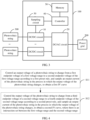
- FIG. 3 is a principle block diagram of a converter according to an embodiment of this application.
- the converter 100 in FIG. 1 may be implemented by using a structure in FIG. 3 .
- the converter 100 includes a DC/DC circuit 10, a DC/AC circuit 20, a sampling circuit 30, a controller 40, and a memory 50.
- Functions of the DC/DC circuit 10, the DC/AC circuit 20, the sampling circuit 30, the controller 40, and the memory 50 may be implemented by using an integrated circuit.
- the DC-DC DC/DC circuit 10, the DC-AC DC/AC circuit 20, the sampling circuit 30, the controller 40, and the memory 50 are integrated on a PCB (Printed Circuit Board, printed circuit board).
- the printed circuit board also referred to as a printed wire board, is an important electronic part, is a support of an electronic component, and is a carrier electrically connected to the electronic component.
- the converter 100 includes at least one DC/DC circuit 10.
- Each DC/DC circuit 10 is correspondingly connected to one photovoltaic string 300 that is used as an input end of the converter 100.
- the DC/DC circuit 10 is configured to adjust an output voltage of the photovoltaic string 300.
- the converter 100 may include only one DC/DC circuit 10, and the DC/DC circuit 10 is connected to at least one photovoltaic string 300.
- the DC/DC circuit 10 has a plurality of input ends.
- the DC/DC circuit 10 may be omitted. In this case, the photovoltaic string 300 needs to be connected to an input end of the DC/AC circuit 20.
- the DC/DC circuit 10 may work in a power conversion mode, and is configured to: perform power conversion on direct-current electric energy of the photovoltaic string 300 at the input end, and then output the converted direct-current electric energy to an output end.
- the DC/DC circuit 10 may work in a pass-through mode, and directly connect the input end and the output end.
- the DC/DC circuit 10 may be set based on a specific application environment, for example, may be set to a buck circuit, a boost circuit, or a buck-boost circuit.
- An input end of the DC/AC circuit 20 is electrically connected to the DC/DC circuit 10, and an output end of the DC/AC circuit 20 is electrically connected to the power grid 500, to convert direct-current electric energy into alternating-current electric energy, and input the alternating-current electric energy to the power grid 500.
- the DC/AC circuit 20 may be omitted.
- the converter 100 can include only the DC/DC circuit.
- the sampling circuit 30 is electrically connected to the DC/DC circuit 10, to detect an output voltage of each photovoltaic string 300 and a current corresponding to the output voltage.
- the sampling circuit 30 may include a sensor, for example, a current sensor.
- the controller 40 is separately electrically connected to the DC/DC circuit 10, the DC/AC circuit 20, the sampling circuit 30, and the memory 50.
- the controller 40 is a part that can coordinate work of all parts based on a function requirement of an instruction, is a nerve center and a command center of a system, usually includes three parts: an instruction register IR (Instruction Register), a program counter PC (Program Counter), and an operation controller OC (Operation Controller), and plays an important role in coordinating ordered work of the entire system.
- the controller 40 herein may be one or more devices, circuits, and/or processing cores for processing data (for example, a computer program instruction).
- the controller 40 may be a processor or may be a collective term of a plurality of processing elements.
- the processor 40 may be a general-purpose central processing unit (Central Processing Unit, CPU), or may be an application-specific integrated circuit (application-specific Integrated Circuit, ASIC), or one or more integrated circuits for controlling program execution of a solution of this application, for example, one or more microprocessors (Digital Signal Processor, DSP), or one or more field programmable gate arrays (Field Programmable Gate Array, FPGA).
- the processor 40 may include one or more CPUs.
- the memory 50 may be a read-only memory (read-only memory, ROM) or another type of static storage device that can store static information and instructions, or a random access memory (random access memory, RAM) or another type of dynamic storage device that can store information and instructions, or may be an electrically erasable programmable read-only memory (Electrically Erasable Programmable Read-Only Memory, EEPROM), a compact disc read-only memory (Compact Disc Read-Only Memory, CD-ROM) or another compact disc storage, an optical disc storage (including a compressed optical disc, a laser disc, an optical disc, a digital versatile disc, a Blu-ray disc, and the like), a disk storage medium or another magnetic storage device, or any other medium that can be used to carry or store expected program code in a form of an instruction or a data structure and that can be accessed by a computer.
- the memory is not limited thereto.
- the memory 50 may exist independently.
- the memory 50 may alternatively be integrated with the controller 40.
- the memory 50 is further configured to store application code for execution of the solution of this application, and the execution is controlled by the controller 40.
- the controller 50 is configured to execute the application code stored in the memory 40.
- the structure illustrated in this embodiment of this application constitutes no specific limitation on the converter 100.
- the converter 100 may include more or fewer parts than those shown in the figure, or combine some parts, or split some parts, or have different part arrangements.
- the parts shown in the figure may be implemented by using hardware, software, or a combination of software and hardware.
- the converter 100 may be further configured to perform IV curve scanning on the photovoltaic string 300 connected to the converter 100, to detect whether the photovoltaic string 300 connected to the converter 100 is defective or damaged.
- an IV curve can also be used to indicate information such as a current power generation capability and working condition of the photovoltaic string 300.
- a light change exerts relatively large impact on an IV output feature of the photovoltaic string. If there is a light change in a process in which the photovoltaic system performs IV curve scanning on the photovoltaic string, an IV curve that is of the photovoltaic string and that is obtained through detection cannot accurately reflect the IV output feature of the photovoltaic string.
- an embodiment of this application further discloses a parametric curve scanning method for a photovoltaic string. This method is applied to the converter 100.
- the parametric curve includes one of a current-voltage IV curve or a power-voltage PV curve.
- the IV curve is used as an example for description.
- FIG. 4 is a flowchart of an IV curve scanning method for a photovoltaic string according to an embodiment of this application. As shown in FIG. 4 , the IV curve scanning method for the photovoltaic string includes the following steps.
- Step S 11 Control an output voltage of the photovoltaic string to change from a first endpoint voltage of a first voltage range to a second endpoint voltage of the first voltage range according to a first preset rule, and sample an output current of the photovoltaic string in the process in which the output voltage of the photovoltaic string changes, to obtain a first IV curve.
- the first voltage range is a voltage scanning range including a maximum output voltage and a minimum output voltage of the photovoltaic string in a process of scanning the first IV curve.
- the maximum output voltage of the photovoltaic string may be an open-circuit voltage, and a minimum output voltage value may be 0 V.
- the first preset rule is at least one of a rule in which a voltage drops by a fixed voltage difference or a rule in which a voltage drops by a changeable voltage difference.
- a preset rule in which the converter 100 controls an output voltage of the photovoltaic string 300 to change from an open-circuit voltage to a preset minimum value may be that the output voltage gradually decreases by a fixed voltage difference (for example, 25 V), or gradually decreases according to the rule in which a voltage drops by a changeable voltage difference.
- the rule in which a voltage drops by a changeable voltage difference specifically means that the voltage drops relatively fast near the open-circuit voltage of the photovoltaic string or the preset minimum value, and drops relatively slow in a middle part.
- the first preset rule may be another rule that can be used to implement a voltage change. This is not specifically limited herein.
- Step S12 Control the output voltage of the photovoltaic string to change from a third endpoint voltage of a second voltage range to a fourth endpoint voltage of the second voltage range according to a second preset rule, and sample an output current of the photovoltaic string in the process in which the output voltage of the photovoltaic string changes, to obtain a second IV curve, where there is an intersection set between the first voltage range and the second voltage range.
- the second voltage range is a voltage scanning range including a maximum output voltage and a minimum output voltage of the photovoltaic string in a process of scanning the second IV curve.
- the maximum output voltage of the photovoltaic string may be an open-circuit voltage, and a minimum output voltage may be 0 V.
- the second preset rule is similar to the first preset rule. Details are not described herein again.
- step S11 and step S12 may be implemented by the DC/DC circuit 10 and the sampling circuit 30.
- the DC/DC circuit 10 actively adjusts input power corresponding to the photovoltaic string 300, to further control the output voltage of the photovoltaic string 300 to change to a corresponding endpoint voltage.
- IV curve scanning is separately performed on the photovoltaic string in the first voltage range and the second voltage range, and there is an intersection set between the first voltage range and the second voltage range, so that the first IV curve and the second IV curve that are obtained include parts corresponding to a same voltage.
- currents corresponding to the same voltage are obtained at different time points, so that it can be determined, by comparing the currents corresponding to the same voltage part, whether the currently obtained IV curve is affected by light, to further determine whether the currently obtained IV curve is valid, thereby improving scanning reliability.
- no test device needs to be additionally added, to effectively reduce a quantity of hardware devices that need to be provided, and reduce curve scanning costs.
- FIG. 5 is a flowchart of an IV curve scanning method for a photovoltaic string according to another embodiment of this application. A difference from FIG. 4 is that the IV curve scanning method in this implementation further includes the following steps.
- Step S13 Determine whether an IV curve scanning instruction is received. If the IV curve scanning instruction is received, step S11 is performed; or if the IV curve scanning instruction is not received, step S13 continues to be performed.
- the converter 100 is initially in a normal on-grid state. Therefore, only when the converter 100 receives an IV curve scanning instruction sent by a host computer, the converter 100 can determine that an IV curve scanning task that needs to be performed. In other words, in this implementation, step S13 further needs to be performed before step S11 is performed.
- Step S14 Determine, based on the first IV curve and the second IV curve, whether the currently scanned IV curve is affected by a light change. If the currently scanned IV curve is not affected by the light change, step S15 is performed; or if the currently scanned IV curve is affected by the light change, step S16 is performed.
- the first IV curve and the second IV curve may be compared, to determine whether the currently scanned IV curve is affected by the light change.
- the controller 40 compares the first parametric curve and the second parametric curve, to determine whether light intensity corresponding to the first IV curve and light intensity corresponding to the second IV curve change. Specifically, if an absolute value of a difference between current values corresponding to a same voltage point that are on the first IV curve and the second IV curve is less than a preset threshold, the controller 40 determines that the current IV curve is not affected by light, in other words, the currently obtained IV curve is valid.
- a same output voltage of a photovoltaic string 300 corresponds to a same current if light intensity does not change.
- the preset threshold may be determined based on an actual application. This is not limited herein.
- Step S15 Process the first IV curve and the second IV curve, to obtain a final IV curve.
- the first IV curve and the second IV curve that are currently obtained are not affected by the light change, it indicates that both the first IV curve and the second IV curve are valid.
- the first IV curve and the second IV curve may be comprehensively processed. For example, an average current of currents corresponding to a same voltage point is obtained, and then the final IV curve is obtained and sent to the host computer.
- Step S16 Send an abnormal signal.
- the host computer may determine, based on feedback, whether to send a parametric curve scanning instruction again.
- the first endpoint voltage is greater than the second endpoint voltage.
- the first endpoint voltage is an upper limit voltage of the first voltage range
- the second endpoint voltage is a lower limit voltage of the first voltage range.
- the third endpoint voltage is less than the fourth endpoint voltage.
- the third endpoint voltage is a lower limit voltage of the second voltage range
- the fourth endpoint voltage is an upper limit voltage of the second voltage range.
- the output voltage of the photovoltaic string 300 is first controlled to change from the upper limit voltage of the first voltage range to the lower limit voltage of the first voltage range according to the first preset rule, to scan the first IV curve; and then the output voltage of the photovoltaic string 300 is controlled to change from the lower limit voltage of the second voltage range to the upper limit voltage of the second voltage range according to the second preset rule, to scan the second IV curve.
- a scanning endpoint of the first IV curve is relatively close to a scanning startpoint of the second IV curve. Therefore, an IV curve scanning speed can be increased.
- the upper limit voltage of the first voltage range is set to be less than or equal to the open-circuit voltage Voc of the string and greater than a maximum power point voltage Vmpp of the string.
- the upper limit voltage of the first voltage range may be close to and slightly less than the open-circuit voltage of the string.
- the lower limit voltage of the first voltage range is set to be greater than or equal to zero and less than the maximum power point voltage Vmpp of the string. In an actual application, the lower limit voltage of the first voltage range may be close to and slightly greater than zero.
- the upper limit voltage of the second voltage range is set to be less than or equal to the open-circuit voltage Voc of the string and greater than the maximum power point voltage Vmpp of the string. In an actual application, the upper limit voltage of the second voltage range may be close to and slightly less than the open-circuit voltage of the string.
- the lower limit voltage of the second voltage range is set to be greater than or equal to zero and less than the maximum power point voltage Vmpp of the string. In an actual application, the lower limit voltage of the second voltage range may be close to and slightly greater than zero.
- the upper limit voltage of the second voltage range may be equal to the upper limit voltage of the first voltage range, or may be unequal to the upper limit voltage of the first voltage range.
- the lower limit voltage of the second voltage range may be equal to the lower limit voltage of the first voltage range, or may be unequal to the lower limit voltage of the first voltage range.
- the upper limit voltage of the first voltage range is equal to the upper limit voltage of the second voltage range
- the lower limit voltage of the first voltage range is equal to the lower limit voltage of the second voltage range
- the first preset rule and the second preset rule each are a rule in which a voltage changes by a fixed voltage difference.
- the first preset rule is a rule in which a voltage drops by a fixed voltage difference
- the second preset rule is a rule in which a voltage rises by a fixed voltage difference.
- 32 sampling points may be selected in each of the first voltage range and the second voltage range.
- the upper limit voltage of the first voltage range is the open-circuit voltage Voc of the photovoltaic string 300, and the lower limit voltage of the first voltage range is 0 V.
- the sampling points in the first voltage range are exactly the same as the sampling points in the second voltage range, so that a calculation amount is reduced, and a comparison speed is improved.
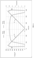
- FIG. 6 is a diagram of an IV scanning waveform of a photovoltaic string according to an embodiment of this application. To further improve comparison efficiency, data at two sampling points is completely the same.
- a time-related waveform F1 in the first voltage range is symmetrical to a time-related waveform F2 in the second voltage range.
- a1 is the upper limit voltage of the first voltage range
- bl is the lower limit voltage of the first voltage range
- c1 is the lower limit voltage of the second voltage range
- d1 is the upper limit voltage of the second voltage range.
- the first endpoint voltage is less than the second endpoint voltage.
- the first endpoint voltage is the lower limit voltage of the first voltage range
- the second endpoint voltage is the upper limit voltage of the first voltage range.
- the third endpoint voltage is greater than the fourth endpoint voltage.
- the third endpoint voltage is the upper limit voltage of the second voltage range
- the fourth endpoint voltage is the lower limit voltage of the second voltage range.
- the output voltage of the photovoltaic string 300 is first controlled to change from the lower limit voltage of the first voltage range to the upper limit voltage of the first voltage range according to the first preset rule, to scan the first IV curve; and then the output voltage of the photovoltaic string 300 is controlled to change from the upper limit voltage of the second voltage range to the lower limit voltage of the second voltage range according to the second preset rule, to scan the second IV curve.
- Other details are the same as or similar to those in the foregoing embodiments, and are not described herein again.
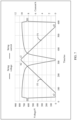
- a time-related waveform F3 in the first voltage range is symmetrical to a time-related waveform F4 in the second voltage range.
- a2 is the lower limit voltage of the first voltage range
- b2 is the upper limit voltage of the first voltage range
- c2 is the upper limit voltage of the second voltage range
- d2 is the lower limit voltage of the second voltage range.
- FIG. 8 is a diagram of a function module of a converter according to an non-claimed embodiment of this application.
- a converter 100 is presented in a form of a function unit.
- the "unit" herein may be an application-specific integrated circuit, a controller and a memory that execute one or more software or firmware programs, an integrated logic circuit, and/or another device that can provide the foregoing function.
- the converter 100 may be in a form shown in FIG. 8 .
- the converter 100 includes an adjustment unit 101, an obtaining unit 102, a determining unit 103, and a processing unit 104.
- the adjustment unit 101 is configured to control an output voltage of the photovoltaic string to change from a first endpoint voltage of a first voltage range to a second endpoint voltage of the first voltage range according to a first preset rule.
- the obtaining unit 102 is configured to obtain a current of the photovoltaic string in the process in which the output voltage change of the photovoltaic string changes, to scan a first IV curve.
- the adjustment unit 101 is further configured to control the output voltage of the photovoltaic string to change from a third endpoint voltage of a second voltage range to a fourth endpoint voltage of the second voltage range according to a second preset rule.
- the obtaining unit 102 is further configured to obtain a current of the photovoltaic string in the process in which the output voltage of the photovoltaic string changes, to scan the second IV curve.
- the determining unit 103 is configured to determine, based on the first IV curve and the second IV curve, whether the currently scanned parametric curve is affected by a light change. Specifically, the determining unit 103 is configured to: when an absolute value of a difference between the corresponding parameter values of a same voltage point that are on the first IV curve and the second IV curve is less than a preset threshold, determine that the currently scanned IV curve is not affected by the light change.
- the processing unit 104 is configured to process the first IV curve and the second IV curve when it is determined that the currently scanned curve is not affected by the light change, to obtain a final IV curve.
- the processing unit 104 is further configured to send an abnormal signal when it is determined that the currently scanned curve is affected by the light change.
- the adjustment unit 101 may be implemented by a DC/DC circuit 101.
- the obtaining unit 102 may be implemented by a sampling circuit 20, and the determining unit 103 and the processing unit 104 may be implemented by a controller 50.
- An embodiment of this application further provides a computer storage medium, configured to store computer software instructions used by the converter shown in FIG. 8 .
- the computer software instructions include a program designed for performing the foregoing method embodiment.
- the stored program is executed, to implement IV curve scanning on a photovoltaic string, and further determine whether an IV curve is affected by the light change.
- function units in the embodiments of this application may be integrated into one processing unit, or each of the units may exist alone physically, or two or more units are integrated into one unit.
- the integrated unit may be implemented in a form of hardware, or may be implemented in a form of hardware in addition to a software function unit.
- a sequence of the steps of the method in the embodiments of this application may be adjusted, combined, or removed based on an actual requirement.
- Implementations of this application may be randomly combined, to achieve different technical effects.
- All or some of the foregoing embodiments may be implemented by using software, hardware, firmware, or any combination thereof.
- the embodiments may be implemented completely or partially in a form of a computer program product.
- the computer program product includes one or more computer instructions.
- the computer may be a general-purpose computer, a dedicated computer, a computer network, or other programmable apparatuses.
- the computer instructions may be stored in a computer-readable storage medium or may be transmitted from a computer-readable storage medium to another computer-readable storage medium.
- the computer instructions may be transmitted from a website, computer, server, or data center to another website, computer, server, or data center in a wired (for example, a coaxial cable, an optical fiber, or a digital subscriber line) or wireless (for example, infrared, radio, or microwave) manner.
- the computer-readable storage medium may be any usable medium accessible by a computer, or a data storage device, such as a server or a data center, integrating one or more usable media.
- the usable medium may be a magnetic medium (for example, a floppy disk, a hard disk, or a magnetic tape), an optical medium (for example, a DVD), a semiconductor medium (for example, a solid-state drive Solid State Disk), or the like.
Landscapes
- Engineering & Computer Science (AREA)
- Power Engineering (AREA)
- Control Of Electrical Variables (AREA)
- Photovoltaic Devices (AREA)
- Supply And Distribution Of Alternating Current (AREA)
Claims (15)
- Parameterkurvenabtastverfahren für einen Photovoltaikstrang (300), das auf ein Photovoltaik-Leistungserzeugungssystem (1000) angewendet wird, wobei das Photovoltaik-Leistungserzeugungssystem (1000) einen Umrichter (100) und mindestens einen mit dem Umrichter (100) verbundenen Photovoltaikstrang (300) umfasst, und wobei das Abtastverfahren Folgendes umfasst:Steuern einer Ausgangsspannung des Photovoltaikstrangs (300) derart, dass sie sich von einer ersten Endpunktspannung eines ersten Spannungsbereichs zu einer zweiten Endpunktspannung des ersten Spannungsbereichs gemäß einer ersten voreingestellten Regel ändert, und Erhalten eines Stromparameters oder eines Leistungsparameters des Photovoltaikstrangs (300) in dem Prozess, in dem sich die Ausgangsspannung des Photovoltaikstrangs (300) ändert, um eine erste Parameterkurve abzutasten; undSteuern der Ausgangsspannung des Photovoltaikstrangs (300) derart, dass sie sich von einer dritten Endpunktspannung eines zweiten Spannungsbereichs zu einer vierten Endpunktspannung des zweiten Spannungsbereichs gemäß einer zweiten voreingestellten Regel ändert, und Erhalten eines Stromparameters oder eines Leistungsparameters des Photovoltaikstrangs (300) in dem Prozess, in dem sich die Ausgangsspannung des Photovoltaikstrangs (300) ändert, um eine zweite Parameterkurve abzutasten, wobei es eine Überschneidung gibt, die zwischen dem ersten Spannungsbereich und dem zweiten Spannungsbereich eingestellt ist,dadurch gekennzeichnet, dass das Abtastverfahren ferner Folgendes umfasst:
die erste Endpunktspannung ist größer als die zweite Endpunktspannung und die dritte Endpunktspannung ist kleiner als die vierte Endpunktspannung; oder die erste Endpunktspannung ist kleiner als die zweite Endpunktspannung und die dritte Endpunktspannung ist größer als die vierte Endpunktspannung. - Abtastverfahren nach Anspruch 1, wobei die erste Endpunktspannung gleich der vierten Endpunktspannung ist und/oder die zweite Endpunktspannung gleich der dritten Endpunktspannung ist.
- Abtastverfahren nach Anspruch 2, wobei eine zeitbezogene Wellenform in dem ersten Spannungsbereich symmetrisch zu einer zeitbezogenen Wellenform in dem zweiten Spannungsbereich ist.
- Abtastverfahren nach Anspruch 1, wobei die erste voreingestellte Regel eine Regel ist, in der eine Spannung um eine festgelegte Spannungsdifferenz abfällt, und die zweite voreingestellte Regel eine Regel ist, in der eine Spannung um eine festgelegte Spannungsdifferenz ansteigt; oder die erste voreingestellte Regel eine Regel ist, in der eine Spannung um eine festgelegte Spannungsdifferenz ansteigt, und die zweite voreingestellte Regel eine Regel ist, in der eine Spannung um eine festgelegte Spannungsdifferenz abfällt.
- Abtastverfahren nach einem der Ansprüche 1 bis 4, wobei das Abtastverfahren ferner Folgendes umfasst:
Bestimmen, basierend auf der ersten Parameterkurve und der zweiten Parameterkurve, ob die derzeit abgetastete Parameterkurve durch eine Lichtänderung beeinflusst ist. - Abtastverfahren nach Anspruch 5, wobei das Bestimmen, basierend auf der ersten Parameterkurve und der zweiten Parameterkurve, ob die derzeit abgetastete Parameterkurve durch eine Lichtänderung beeinflusst ist, Folgendes umfasst:
Vergleichen der ersten Parameterkurve und der zweiten Parameterkurve, um zu bestimmen, ob eine Lichtintensität, die der ersten Parameterkurve entspricht, und eine Lichtintensität, die der zweiten Parameterkurve entspricht, sich ändern. - Abtastverfahren nach Anspruch 5 oder 6, wobei das Abtastverfahren ferner Folgendes umfasst:
falls ein absoluter Wert einer Differenz zwischen den entsprechenden Parameterwerten eines gleichen Spannungspunkts, die sich auf der ersten Parameterkurve und der zweiten Parameterkurve befinden, kleiner als ein voreingestellter Schwellenwert ist, Bestimmen, dass die derzeit abgetastete Parameterkurve nicht durch die Lichtänderung beeinflusst ist. - Umrichter (100), umfassend:eine DC/DC-Schaltung (101), die dazu konfiguriert ist, eine Ausgangsspannung des Photovoltaikstrangs (300) derart zu steuern, dass sie sich von einer ersten Endpunktspannung eines ersten Spannungsbereichs zu einer zweiten Endpunktspannung des ersten Spannungsbereichs gemäß einer ersten voreingestellten Regel ändert; undeine Abfrageschaltung (20), die dazu konfiguriert ist, einen Stromparameter und/oder einen Leistungsparameter des Photovoltaikstrangs (300) in dem Prozess zu erhalten, in dem sich die Ausgangsspannungsänderung des Photovoltaikstrangs (300) ändert, um eine erste Parameterkurve abzutasten, wobeidie DC/DC-Schaltung (101) ferner dazu konfiguriert ist, die Ausgangsspannung des Photovoltaikstrangs (300) derart zu steuern, dass sie sich von einer dritten Endpunktspannung eines zweiten Spannungsbereichs zu einer vierten Endpunktspannung des zweiten Spannungsbereichs gemäß einer zweiten voreingestellten Regel ändert; unddie Abfrageschaltung (20) ferner dazu konfiguriert ist, einen Stromparameter und/oder einen Leistungsparameter des Photovoltaikstrangs (300) in dem Prozess zu erhalten, in dem sich die Ausgangsspannung des Photovoltaikstrangs (300) ändert, um eine zweite Parameterkurve abzutasten, wobei es eine Überschneidung gibt, die zwischen dem ersten Spannungsbereich und dem zweiten Spannungsbereich eingestellt ist,dadurch gekennzeichnet, dass die erste Endpunktspannung größer als die zweite Endpunktspannung ist und die dritte Endpunktspannung kleiner als die vierte Endpunktspannung ist; oder die erste Endpunktspannung kleiner als die zweite Endpunktspannung ist und die dritte Endpunktspannung größer als die vierte Endpunktspannung ist.
- Umrichter nach Anspruch 8, wobei die Endpunktspannung gleich der vierten Endpunktspannung ist und/oder die zweite Endpunktspannung gleich der dritten Endpunktspannung ist.
- Umrichter (100) nach Anspruch 9, wobei eine zeitbezogene Wellenform in dem ersten Spannungsbereich symmetrisch zu einer zeitbezogenen Wellenform in dem zweiten Spannungsbereich ist.
- Umrichter (100) nach Anspruch 8, wobei die erste voreingestellte Regel eine Regel ist, in der eine Spannung um eine festgelegte Spannungsdifferenz abfällt, und die zweite voreingestellte Regel eine Regel ist, in der eine Spannung um eine festgelegte Spannungsdifferenz ansteigt; oder die erste voreingestellte Regel eine Regel ist, in der eine Spannung um eine festgelegte Spannungsdifferenz ansteigt, und die zweite voreingestellte Regel eine Regel ist, in der eine Spannung um eine festgelegte Spannungsdifferenz abfällt.
- Umrichter nach einem der Ansprüche 8 bis 11, wobei der Umrichter ferner eine Steuerung umfasst, wobei die Steuerung separat elektrisch mit der Abfrageschaltung und der DC/DC-Schaltung verbunden ist, und wobei die Steuerung dazu konfiguriert ist, basierend auf der ersten Parameterkurve und der zweiten Parameterkurve zu bestimmen, ob die derzeit abgetastete Parameterkurve durch eine Lichtänderung beeinflusst ist.
- Umrichter (100) nach Anspruch 12, wobei die Steuerung (50) dazu konfiguriert ist, die erste Parameterkurve und die zweite Parameterkurve zu vergleichen, um zu bestimmen, ob eine Lichtintensität, die der ersten Parameterkurve entspricht, und eine Lichtintensität, die der zweiten Parameterkurve entspricht, sich ändern.
- Umrichter (100) nach Anspruch 12 oder 13, wobei die Steuerung (50) zu Folgendem konfiguriert ist: wenn ein absoluter Wert einer Differenz zwischen den entsprechenden Parameterwerten eines gleichen Spannungspunkts, die sich auf der ersten Parameterkurve und der zweiten Parameterkurve befinden, kleiner als ein voreingestellter Schwellenwert ist, Bestimmen, dass die derzeit abgetastete Parameterkurve nicht durch die Lichtänderung beeinflusst ist.
- Photovoltaik-Leistungserzeugungssystem (1000), umfassend ein Leistungsnetz (500) und mindestens einen Photovoltaikstrang (300), wobei das Photovoltaik-Leistungserzeugungssystem (1000) ferner den Umrichter (100) nach einem der Ansprüche 8 bis 11 umfasst, wobei ein Eingangsende des Umrichters (100) mit dem mindestens einen Photovoltaikstrang (300) verbunden ist und ein Ausgangsende des Umrichters (100) mit dem Leistungsnetz (500) verbunden ist.
Priority Applications (2)
| Application Number | Priority Date | Filing Date | Title |
|---|---|---|---|
| EP25193238.0A EP4668530A3 (de) | 2020-03-31 | 2020-03-31 | Parametrisches kurvenabtastverfahren für fotovoltaischen string, wandler und fotovoltaisches stromerzeugungssystem |
| EP23178499.2A EP4258505B1 (de) | 2020-03-31 | 2020-03-31 | Parametrisches kurvenabtastverfahren, fotovoltaik-string, wandler und fotovoltaisches energieerzeugungssystem |
Applications Claiming Priority (1)
| Application Number | Priority Date | Filing Date | Title |
|---|---|---|---|
| PCT/CN2020/082317 WO2021195929A1 (zh) | 2020-03-31 | 2020-03-31 | 光伏组串的参数曲线扫描方法、变换器及光伏发电系统 |
Related Child Applications (3)
| Application Number | Title | Priority Date | Filing Date |
|---|---|---|---|
| EP23178499.2A Division-Into EP4258505B1 (de) | 2020-03-31 | 2020-03-31 | Parametrisches kurvenabtastverfahren, fotovoltaik-string, wandler und fotovoltaisches energieerzeugungssystem |
| EP23178499.2A Division EP4258505B1 (de) | 2020-03-31 | 2020-03-31 | Parametrisches kurvenabtastverfahren, fotovoltaik-string, wandler und fotovoltaisches energieerzeugungssystem |
| EP25193238.0A Division EP4668530A3 (de) | 2020-03-31 | 2020-03-31 | Parametrisches kurvenabtastverfahren für fotovoltaischen string, wandler und fotovoltaisches stromerzeugungssystem |
Publications (3)
| Publication Number | Publication Date |
|---|---|
| EP3926823A1 EP3926823A1 (de) | 2021-12-22 |
| EP3926823A4 EP3926823A4 (de) | 2022-04-13 |
| EP3926823B1 true EP3926823B1 (de) | 2023-07-26 |
Family
ID=75514820
Family Applications (3)
| Application Number | Title | Priority Date | Filing Date |
|---|---|---|---|
| EP20922468.2A Active EP3926823B1 (de) | 2020-03-31 | 2020-03-31 | Parametrisches kurvenabtastverfahren, fotovoltaik-string, wandler und fotovoltaisches energieerzeugungssystem |
| EP23178499.2A Active EP4258505B1 (de) | 2020-03-31 | 2020-03-31 | Parametrisches kurvenabtastverfahren, fotovoltaik-string, wandler und fotovoltaisches energieerzeugungssystem |
| EP25193238.0A Pending EP4668530A3 (de) | 2020-03-31 | 2020-03-31 | Parametrisches kurvenabtastverfahren für fotovoltaischen string, wandler und fotovoltaisches stromerzeugungssystem |
Family Applications After (2)
| Application Number | Title | Priority Date | Filing Date |
|---|---|---|---|
| EP23178499.2A Active EP4258505B1 (de) | 2020-03-31 | 2020-03-31 | Parametrisches kurvenabtastverfahren, fotovoltaik-string, wandler und fotovoltaisches energieerzeugungssystem |
| EP25193238.0A Pending EP4668530A3 (de) | 2020-03-31 | 2020-03-31 | Parametrisches kurvenabtastverfahren für fotovoltaischen string, wandler und fotovoltaisches stromerzeugungssystem |
Country Status (7)
| Country | Link |
|---|---|
| US (1) | US11575266B2 (de) |
| EP (3) | EP3926823B1 (de) |
| JP (1) | JP2023511565A (de) |
| CN (2) | CN115498959A (de) |
| AU (1) | AU2020439859B2 (de) |
| ES (2) | ES2961249T3 (de) |
| WO (1) | WO2021195929A1 (de) |
Families Citing this family (4)
| Publication number | Priority date | Publication date | Assignee | Title |
|---|---|---|---|---|
| CN114337541B (zh) * | 2022-01-07 | 2024-04-12 | 阳光电源股份有限公司 | 一种光伏组件的iv扫描方法、光伏系统 |
| CN114938201B (zh) * | 2022-04-29 | 2023-11-10 | 帝森克罗德集团有限公司 | 光伏并网逆变器的扫描方法及装置 |
| CN116545379A (zh) * | 2023-05-17 | 2023-08-04 | 阳光电源股份有限公司 | 一种多路输入变换器的iv扫描方法及装置 |
| CN119324680B (zh) * | 2024-12-18 | 2025-04-18 | 锦浪科技股份有限公司 | 一种iv曲线扫描方法 |
Family Cites Families (15)
| Publication number | Priority date | Publication date | Assignee | Title |
|---|---|---|---|---|
| JP4327651B2 (ja) * | 2004-04-28 | 2009-09-09 | シャープ株式会社 | 測定装置および測定方法 |
| JP4556677B2 (ja) * | 2005-01-18 | 2010-10-06 | オムロン株式会社 | カーブトレーサを内蔵したパワーコンディショナ |
| JP5462821B2 (ja) * | 2011-03-08 | 2014-04-02 | 株式会社日立パワーソリューションズ | 太陽電池異常判定装置および太陽電池異常判定方法 |
| US10663500B2 (en) * | 2011-07-25 | 2020-05-26 | Clean Power Research, L.L.C. | System and method for estimating photovoltaic energy generation through linearly interpolated irradiance observations with the aid of a digital computer |
| US20130194564A1 (en) * | 2012-01-26 | 2013-08-01 | Solarworld Industries America, Inc. | Method and apparatus for measuring photovoltaic cells |
| US20150091546A1 (en) * | 2013-09-27 | 2015-04-02 | Tel Solar Ag | Power measurement analysis of photovoltaic modules |
| JP6295724B2 (ja) * | 2014-02-28 | 2018-03-20 | オムロン株式会社 | 太陽電池の評価装置、評価方法及び、太陽光発電システム |
| JP6432136B2 (ja) * | 2014-03-14 | 2018-12-05 | オムロン株式会社 | 評価装置 |
| JP6474305B2 (ja) * | 2015-04-23 | 2019-02-27 | 株式会社日立製作所 | 太陽光発電システムの診断方法及び監視装置 |
| CN105680797B (zh) * | 2016-03-01 | 2018-03-27 | 华为技术有限公司 | 一种检测光伏组串的电流电压曲线的方法及系统 |
| CN106357220B (zh) * | 2016-10-12 | 2018-08-17 | 福州大学 | 一种分布式光伏组串及组件iv特性曲线在线测量系统 |
| CN106712716B (zh) * | 2017-02-10 | 2019-02-01 | 阳光电源股份有限公司 | 一种光伏组件的iv曲线扫描方法及优化器 |
| CN107017836B (zh) * | 2017-06-12 | 2019-03-05 | 阳光电源股份有限公司 | 一种光伏发电系统及其组件iv曲线扫描方法 |
| CN107508551B (zh) * | 2017-09-14 | 2019-10-29 | 阳光电源股份有限公司 | 一种集中式光伏发电系统的iv扫描方法 |
| CN110677118B (zh) * | 2019-09-23 | 2022-01-11 | 华为数字能源技术有限公司 | 优化器、光伏发电系统及光伏组件的iv曲线扫描方法 |
-
2020
- 2020-03-31 CN CN202211063780.5A patent/CN115498959A/zh active Pending
- 2020-03-31 EP EP20922468.2A patent/EP3926823B1/de active Active
- 2020-03-31 ES ES20922468T patent/ES2961249T3/es active Active
- 2020-03-31 CN CN202080005064.4A patent/CN112703669B/zh active Active
- 2020-03-31 AU AU2020439859A patent/AU2020439859B2/en active Active
- 2020-03-31 WO PCT/CN2020/082317 patent/WO2021195929A1/zh not_active Ceased
- 2020-03-31 ES ES23178499T patent/ES3040283T3/es active Active
- 2020-03-31 EP EP23178499.2A patent/EP4258505B1/de active Active
- 2020-03-31 EP EP25193238.0A patent/EP4668530A3/de active Pending
- 2020-03-31 JP JP2022544191A patent/JP2023511565A/ja active Pending
-
2022
- 2022-03-08 US US17/689,863 patent/US11575266B2/en active Active
Also Published As
| Publication number | Publication date |
|---|---|
| EP3926823A1 (de) | 2021-12-22 |
| US11575266B2 (en) | 2023-02-07 |
| ES2961249T3 (es) | 2024-03-11 |
| EP4258505C0 (de) | 2025-09-03 |
| CN112703669B (zh) | 2022-09-09 |
| AU2020439859A1 (en) | 2022-07-21 |
| WO2021195929A1 (zh) | 2021-10-07 |
| US20220190605A1 (en) | 2022-06-16 |
| EP4668530A2 (de) | 2025-12-24 |
| EP4668530A3 (de) | 2026-03-18 |
| EP4258505A2 (de) | 2023-10-11 |
| JP2023511565A (ja) | 2023-03-20 |
| CN115498959A (zh) | 2022-12-20 |
| EP4258505B1 (de) | 2025-09-03 |
| CN112703669A (zh) | 2021-04-23 |
| AU2020439859B2 (en) | 2023-11-30 |
| EP3926823A4 (de) | 2022-04-13 |
| ES3040283T3 (en) | 2025-10-29 |
| EP4258505A3 (de) | 2024-06-05 |
Similar Documents
| Publication | Publication Date | Title |
|---|---|---|
| US11994893B2 (en) | Converter control method, converter, and photovoltaic power generation system | |
| US11575266B2 (en) | Parametric curve scanning method for photovoltaic string, converter, and photovoltaic power generation system | |
| US20230261510A1 (en) | Method and apparatus for controlling busbar voltage of photovoltaic system | |
| CN105680797B (zh) | 一种检测光伏组串的电流电压曲线的方法及系统 | |
| US12062918B2 (en) | Power systems with inverter input voltage control | |
| Hadi et al. | Using Active Filter Controlled by Imperialist Competitive Algorithm ICA for Harmonic Mitigation in Grid-Connected PV Systems. | |
| CN106849153A (zh) | 用于操作逆变器的方法和逆变器 | |
| CN114337541B (zh) | 一种光伏组件的iv扫描方法、光伏系统 | |
| US12176848B2 (en) | Adaptive photovoltaic system | |
| CN118367615A (zh) | 一种光伏发电并网控制方法及系统 | |
| CN118549698A (zh) | 组串型pv非隔离光伏逆变器pv电流检测系统及其检测方法 |
Legal Events
| Date | Code | Title | Description |
|---|---|---|---|
| STAA | Information on the status of an ep patent application or granted ep patent |
Free format text: STATUS: UNKNOWN |
|
| STAA | Information on the status of an ep patent application or granted ep patent |
Free format text: STATUS: THE INTERNATIONAL PUBLICATION HAS BEEN MADE |
|
| PUAI | Public reference made under article 153(3) epc to a published international application that has entered the european phase |
Free format text: ORIGINAL CODE: 0009012 |
|
| STAA | Information on the status of an ep patent application or granted ep patent |
Free format text: STATUS: REQUEST FOR EXAMINATION WAS MADE |
|
| 17P | Request for examination filed |
Effective date: 20210906 |
|
| AK | Designated contracting states |
Kind code of ref document: A1 Designated state(s): AL AT BE BG CH CY CZ DE DK EE ES FI FR GB GR HR HU IE IS IT LI LT LU LV MC MK MT NL NO PL PT RO RS SE SI SK SM TR |
|
| A4 | Supplementary search report drawn up and despatched |
Effective date: 20220315 |
|
| RIC1 | Information provided on ipc code assigned before grant |
Ipc: H02J 3/38 20060101ALI20220309BHEP Ipc: H02S 50/10 20140101AFI20220309BHEP |
|
| GRAP | Despatch of communication of intention to grant a patent |
Free format text: ORIGINAL CODE: EPIDOSNIGR1 |
|
| STAA | Information on the status of an ep patent application or granted ep patent |
Free format text: STATUS: GRANT OF PATENT IS INTENDED |
|
| DAV | Request for validation of the european patent (deleted) | ||
| DAX | Request for extension of the european patent (deleted) | ||
| INTG | Intention to grant announced |
Effective date: 20230313 |
|
| GRAS | Grant fee paid |
Free format text: ORIGINAL CODE: EPIDOSNIGR3 |
|
| GRAA | (expected) grant |
Free format text: ORIGINAL CODE: 0009210 |
|
| STAA | Information on the status of an ep patent application or granted ep patent |
Free format text: STATUS: THE PATENT HAS BEEN GRANTED |
|
| P01 | Opt-out of the competence of the unified patent court (upc) registered |
Effective date: 20230524 |
|
| RIN1 | Information on inventor provided before grant (corrected) |
Inventor name: GU, GUILEI Inventor name: JU, HUALEI Inventor name: XU, ZHIWU |
|
| AK | Designated contracting states |
Kind code of ref document: B1 Designated state(s): AL AT BE BG CH CY CZ DE DK EE ES FI FR GB GR HR HU IE IS IT LI LT LU LV MC MK MT NL NO PL PT RO RS SE SI SK SM TR |
|
| REG | Reference to a national code |
Ref country code: CH Ref legal event code: EP |
|
| REG | Reference to a national code |
Ref country code: IE Ref legal event code: FG4D |
|
| REG | Reference to a national code |
Ref country code: DE Ref legal event code: R096 Ref document number: 602020014679 Country of ref document: DE |
|
| REG | Reference to a national code |
Ref country code: NL Ref legal event code: FP |
|
| REG | Reference to a national code |
Ref country code: LT Ref legal event code: MG9D |
|
| REG | Reference to a national code |
Ref country code: AT Ref legal event code: MK05 Ref document number: 1593122 Country of ref document: AT Kind code of ref document: T Effective date: 20230726 |
|
| PG25 | Lapsed in a contracting state [announced via postgrant information from national office to epo] |
Ref country code: GR Free format text: LAPSE BECAUSE OF FAILURE TO SUBMIT A TRANSLATION OF THE DESCRIPTION OR TO PAY THE FEE WITHIN THE PRESCRIBED TIME-LIMIT Effective date: 20231027 |
|
| PG25 | Lapsed in a contracting state [announced via postgrant information from national office to epo] |
Ref country code: IS Free format text: LAPSE BECAUSE OF FAILURE TO SUBMIT A TRANSLATION OF THE DESCRIPTION OR TO PAY THE FEE WITHIN THE PRESCRIBED TIME-LIMIT Effective date: 20231126 |
|
| PG25 | Lapsed in a contracting state [announced via postgrant information from national office to epo] |
Ref country code: SE Free format text: LAPSE BECAUSE OF FAILURE TO SUBMIT A TRANSLATION OF THE DESCRIPTION OR TO PAY THE FEE WITHIN THE PRESCRIBED TIME-LIMIT Effective date: 20230726 Ref country code: RS Free format text: LAPSE BECAUSE OF FAILURE TO SUBMIT A TRANSLATION OF THE DESCRIPTION OR TO PAY THE FEE WITHIN THE PRESCRIBED TIME-LIMIT Effective date: 20230726 Ref country code: PT Free format text: LAPSE BECAUSE OF FAILURE TO SUBMIT A TRANSLATION OF THE DESCRIPTION OR TO PAY THE FEE WITHIN THE PRESCRIBED TIME-LIMIT Effective date: 20231127 Ref country code: NO Free format text: LAPSE BECAUSE OF FAILURE TO SUBMIT A TRANSLATION OF THE DESCRIPTION OR TO PAY THE FEE WITHIN THE PRESCRIBED TIME-LIMIT Effective date: 20231026 Ref country code: LV Free format text: LAPSE BECAUSE OF FAILURE TO SUBMIT A TRANSLATION OF THE DESCRIPTION OR TO PAY THE FEE WITHIN THE PRESCRIBED TIME-LIMIT Effective date: 20230726 Ref country code: LT Free format text: LAPSE BECAUSE OF FAILURE TO SUBMIT A TRANSLATION OF THE DESCRIPTION OR TO PAY THE FEE WITHIN THE PRESCRIBED TIME-LIMIT Effective date: 20230726 Ref country code: IS Free format text: LAPSE BECAUSE OF FAILURE TO SUBMIT A TRANSLATION OF THE DESCRIPTION OR TO PAY THE FEE WITHIN THE PRESCRIBED TIME-LIMIT Effective date: 20231126 Ref country code: HR Free format text: LAPSE BECAUSE OF FAILURE TO SUBMIT A TRANSLATION OF THE DESCRIPTION OR TO PAY THE FEE WITHIN THE PRESCRIBED TIME-LIMIT Effective date: 20230726 Ref country code: GR Free format text: LAPSE BECAUSE OF FAILURE TO SUBMIT A TRANSLATION OF THE DESCRIPTION OR TO PAY THE FEE WITHIN THE PRESCRIBED TIME-LIMIT Effective date: 20231027 Ref country code: FI Free format text: LAPSE BECAUSE OF FAILURE TO SUBMIT A TRANSLATION OF THE DESCRIPTION OR TO PAY THE FEE WITHIN THE PRESCRIBED TIME-LIMIT Effective date: 20230726 Ref country code: AT Free format text: LAPSE BECAUSE OF FAILURE TO SUBMIT A TRANSLATION OF THE DESCRIPTION OR TO PAY THE FEE WITHIN THE PRESCRIBED TIME-LIMIT Effective date: 20230726 |
|
| PG25 | Lapsed in a contracting state [announced via postgrant information from national office to epo] |
Ref country code: PL Free format text: LAPSE BECAUSE OF FAILURE TO SUBMIT A TRANSLATION OF THE DESCRIPTION OR TO PAY THE FEE WITHIN THE PRESCRIBED TIME-LIMIT Effective date: 20230726 |
|
| REG | Reference to a national code |
Ref country code: ES Ref legal event code: FG2A Ref document number: 2961249 Country of ref document: ES Kind code of ref document: T3 Effective date: 20240311 |
|
| REG | Reference to a national code |
Ref country code: DE Ref legal event code: R097 Ref document number: 602020014679 Country of ref document: DE |
|
| PG25 | Lapsed in a contracting state [announced via postgrant information from national office to epo] |
Ref country code: SM Free format text: LAPSE BECAUSE OF FAILURE TO SUBMIT A TRANSLATION OF THE DESCRIPTION OR TO PAY THE FEE WITHIN THE PRESCRIBED TIME-LIMIT Effective date: 20230726 Ref country code: RO Free format text: LAPSE BECAUSE OF FAILURE TO SUBMIT A TRANSLATION OF THE DESCRIPTION OR TO PAY THE FEE WITHIN THE PRESCRIBED TIME-LIMIT Effective date: 20230726 Ref country code: EE Free format text: LAPSE BECAUSE OF FAILURE TO SUBMIT A TRANSLATION OF THE DESCRIPTION OR TO PAY THE FEE WITHIN THE PRESCRIBED TIME-LIMIT Effective date: 20230726 Ref country code: DK Free format text: LAPSE BECAUSE OF FAILURE TO SUBMIT A TRANSLATION OF THE DESCRIPTION OR TO PAY THE FEE WITHIN THE PRESCRIBED TIME-LIMIT Effective date: 20230726 Ref country code: CZ Free format text: LAPSE BECAUSE OF FAILURE TO SUBMIT A TRANSLATION OF THE DESCRIPTION OR TO PAY THE FEE WITHIN THE PRESCRIBED TIME-LIMIT Effective date: 20230726 Ref country code: SK Free format text: LAPSE BECAUSE OF FAILURE TO SUBMIT A TRANSLATION OF THE DESCRIPTION OR TO PAY THE FEE WITHIN THE PRESCRIBED TIME-LIMIT Effective date: 20230726 |
|
| PG25 | Lapsed in a contracting state [announced via postgrant information from national office to epo] |
Ref country code: IT Free format text: LAPSE BECAUSE OF FAILURE TO SUBMIT A TRANSLATION OF THE DESCRIPTION OR TO PAY THE FEE WITHIN THE PRESCRIBED TIME-LIMIT Effective date: 20230726 |
|
| PLBE | No opposition filed within time limit |
Free format text: ORIGINAL CODE: 0009261 |
|
| STAA | Information on the status of an ep patent application or granted ep patent |
Free format text: STATUS: NO OPPOSITION FILED WITHIN TIME LIMIT |
|
| 26N | No opposition filed |
Effective date: 20240429 |
|
| PG25 | Lapsed in a contracting state [announced via postgrant information from national office to epo] |
Ref country code: SI Free format text: LAPSE BECAUSE OF FAILURE TO SUBMIT A TRANSLATION OF THE DESCRIPTION OR TO PAY THE FEE WITHIN THE PRESCRIBED TIME-LIMIT Effective date: 20230726 |
|
| REG | Reference to a national code |
Ref country code: CH Ref legal event code: PL |
|
| PG25 | Lapsed in a contracting state [announced via postgrant information from national office to epo] |
Ref country code: BG Free format text: LAPSE BECAUSE OF FAILURE TO SUBMIT A TRANSLATION OF THE DESCRIPTION OR TO PAY THE FEE WITHIN THE PRESCRIBED TIME-LIMIT Effective date: 20230726 |
|
| PG25 | Lapsed in a contracting state [announced via postgrant information from national office to epo] |
Ref country code: LU Free format text: LAPSE BECAUSE OF NON-PAYMENT OF DUE FEES Effective date: 20240331 |
|
| PG25 | Lapsed in a contracting state [announced via postgrant information from national office to epo] |
Ref country code: MC Free format text: LAPSE BECAUSE OF FAILURE TO SUBMIT A TRANSLATION OF THE DESCRIPTION OR TO PAY THE FEE WITHIN THE PRESCRIBED TIME-LIMIT Effective date: 20230726 |
|
| PG25 | Lapsed in a contracting state [announced via postgrant information from national office to epo] |
Ref country code: MC Free format text: LAPSE BECAUSE OF FAILURE TO SUBMIT A TRANSLATION OF THE DESCRIPTION OR TO PAY THE FEE WITHIN THE PRESCRIBED TIME-LIMIT Effective date: 20230726 Ref country code: LU Free format text: LAPSE BECAUSE OF NON-PAYMENT OF DUE FEES Effective date: 20240331 Ref country code: BG Free format text: LAPSE BECAUSE OF FAILURE TO SUBMIT A TRANSLATION OF THE DESCRIPTION OR TO PAY THE FEE WITHIN THE PRESCRIBED TIME-LIMIT Effective date: 20230726 |
|
| REG | Reference to a national code |
Ref country code: BE Ref legal event code: MM Effective date: 20240331 |
|
| PG25 | Lapsed in a contracting state [announced via postgrant information from national office to epo] |
Ref country code: BE Free format text: LAPSE BECAUSE OF NON-PAYMENT OF DUE FEES Effective date: 20240331 |
|
| PG25 | Lapsed in a contracting state [announced via postgrant information from national office to epo] |
Ref country code: IE Free format text: LAPSE BECAUSE OF NON-PAYMENT OF DUE FEES Effective date: 20240331 |
|
| PG25 | Lapsed in a contracting state [announced via postgrant information from national office to epo] |
Ref country code: IE Free format text: LAPSE BECAUSE OF NON-PAYMENT OF DUE FEES Effective date: 20240331 Ref country code: BE Free format text: LAPSE BECAUSE OF NON-PAYMENT OF DUE FEES Effective date: 20240331 Ref country code: CH Free format text: LAPSE BECAUSE OF NON-PAYMENT OF DUE FEES Effective date: 20240331 |
|
| PGFP | Annual fee paid to national office [announced via postgrant information from national office to epo] |
Ref country code: ES Payment date: 20250408 Year of fee payment: 6 |
|
| PG25 | Lapsed in a contracting state [announced via postgrant information from national office to epo] |
Ref country code: CY Free format text: LAPSE BECAUSE OF FAILURE TO SUBMIT A TRANSLATION OF THE DESCRIPTION OR TO PAY THE FEE WITHIN THE PRESCRIBED TIME-LIMIT; INVALID AB INITIO Effective date: 20200331 |
|
| PG25 | Lapsed in a contracting state [announced via postgrant information from national office to epo] |
Ref country code: HU Free format text: LAPSE BECAUSE OF FAILURE TO SUBMIT A TRANSLATION OF THE DESCRIPTION OR TO PAY THE FEE WITHIN THE PRESCRIBED TIME-LIMIT; INVALID AB INITIO Effective date: 20200331 |
|
| PG25 | Lapsed in a contracting state [announced via postgrant information from national office to epo] |
Ref country code: TR Free format text: LAPSE BECAUSE OF FAILURE TO SUBMIT A TRANSLATION OF THE DESCRIPTION OR TO PAY THE FEE WITHIN THE PRESCRIBED TIME-LIMIT Effective date: 20230726 |
|
| PGFP | Annual fee paid to national office [announced via postgrant information from national office to epo] |
Ref country code: NL Payment date: 20260213 Year of fee payment: 7 |
|
| PGFP | Annual fee paid to national office [announced via postgrant information from national office to epo] |
Ref country code: GB Payment date: 20260209 Year of fee payment: 7 |
|
| PGFP | Annual fee paid to national office [announced via postgrant information from national office to epo] |
Ref country code: DE Payment date: 20260204 Year of fee payment: 7 |
|
| PGFP | Annual fee paid to national office [announced via postgrant information from national office to epo] |
Ref country code: FR Payment date: 20260209 Year of fee payment: 7 |