EP3927237B1 - Reconstruction de phénomènes de fréquence cardiaque dans des données angiographiques - Google Patents
Reconstruction de phénomènes de fréquence cardiaque dans des données angiographiques Download PDFInfo
- Publication number
- EP3927237B1 EP3927237B1 EP20777422.5A EP20777422A EP3927237B1 EP 3927237 B1 EP3927237 B1 EP 3927237B1 EP 20777422 A EP20777422 A EP 20777422A EP 3927237 B1 EP3927237 B1 EP 3927237B1
- Authority
- EP
- European Patent Office
- Prior art keywords
- angiographic
- cardiac frequency
- images
- cardiac
- phenomena
- Prior art date
- Legal status (The legal status is an assumption and is not a legal conclusion. Google has not performed a legal analysis and makes no representation as to the accuracy of the status listed.)
- Active
Links
Images





Classifications
-
- A—HUMAN NECESSITIES
- A61—MEDICAL OR VETERINARY SCIENCE; HYGIENE
- A61B—DIAGNOSIS; SURGERY; IDENTIFICATION
- A61B6/00—Apparatus or devices for radiation diagnosis; Apparatus or devices for radiation diagnosis combined with radiation therapy equipment
- A61B6/46—Arrangements for interfacing with the operator or the patient
- A61B6/461—Displaying means of special interest
- A61B6/463—Displaying means of special interest characterised by displaying multiple images or images and diagnostic data on one display
-
- A—HUMAN NECESSITIES
- A61—MEDICAL OR VETERINARY SCIENCE; HYGIENE
- A61B—DIAGNOSIS; SURGERY; IDENTIFICATION
- A61B6/00—Apparatus or devices for radiation diagnosis; Apparatus or devices for radiation diagnosis combined with radiation therapy equipment
- A61B6/48—Diagnostic techniques
- A61B6/481—Diagnostic techniques involving the use of contrast agents
-
- A—HUMAN NECESSITIES
- A61—MEDICAL OR VETERINARY SCIENCE; HYGIENE
- A61B—DIAGNOSIS; SURGERY; IDENTIFICATION
- A61B6/00—Apparatus or devices for radiation diagnosis; Apparatus or devices for radiation diagnosis combined with radiation therapy equipment
- A61B6/50—Apparatus or devices for radiation diagnosis; Apparatus or devices for radiation diagnosis combined with radiation therapy equipment specially adapted for specific body parts; specially adapted for specific clinical applications
- A61B6/504—Apparatus or devices for radiation diagnosis; Apparatus or devices for radiation diagnosis combined with radiation therapy equipment specially adapted for specific body parts; specially adapted for specific clinical applications for diagnosis of blood vessels, e.g. by angiography
-
- A—HUMAN NECESSITIES
- A61—MEDICAL OR VETERINARY SCIENCE; HYGIENE
- A61B—DIAGNOSIS; SURGERY; IDENTIFICATION
- A61B6/00—Apparatus or devices for radiation diagnosis; Apparatus or devices for radiation diagnosis combined with radiation therapy equipment
- A61B6/52—Devices using data or image processing specially adapted for radiation diagnosis
- A61B6/5211—Devices using data or image processing specially adapted for radiation diagnosis involving processing of medical diagnostic data
- A61B6/5217—Devices using data or image processing specially adapted for radiation diagnosis involving processing of medical diagnostic data extracting a diagnostic or physiological parameter from medical diagnostic data
-
- A—HUMAN NECESSITIES
- A61—MEDICAL OR VETERINARY SCIENCE; HYGIENE
- A61B—DIAGNOSIS; SURGERY; IDENTIFICATION
- A61B6/00—Apparatus or devices for radiation diagnosis; Apparatus or devices for radiation diagnosis combined with radiation therapy equipment
- A61B6/52—Devices using data or image processing specially adapted for radiation diagnosis
- A61B6/5258—Devices using data or image processing specially adapted for radiation diagnosis involving detection or reduction of artifacts or noise
-
- A—HUMAN NECESSITIES
- A61—MEDICAL OR VETERINARY SCIENCE; HYGIENE
- A61B—DIAGNOSIS; SURGERY; IDENTIFICATION
- A61B6/00—Apparatus or devices for radiation diagnosis; Apparatus or devices for radiation diagnosis combined with radiation therapy equipment
- A61B6/52—Devices using data or image processing specially adapted for radiation diagnosis
- A61B6/5288—Devices using data or image processing specially adapted for radiation diagnosis involving retrospective matching to a physiological signal
-
- G—PHYSICS
- G06—COMPUTING OR CALCULATING; COUNTING
- G06T—IMAGE DATA PROCESSING OR GENERATION, IN GENERAL
- G06T12/00—Tomographic reconstruction from projections
- G06T12/10—Image preprocessing, e.g. calibration, positioning of sources or scatter correction
-
- G—PHYSICS
- G06—COMPUTING OR CALCULATING; COUNTING
- G06T—IMAGE DATA PROCESSING OR GENERATION, IN GENERAL
- G06T12/00—Tomographic reconstruction from projections
- G06T12/20—Inverse problem, i.e. transformations from projection space into object space
-
- G—PHYSICS
- G06—COMPUTING OR CALCULATING; COUNTING
- G06T—IMAGE DATA PROCESSING OR GENERATION, IN GENERAL
- G06T7/00—Image analysis
- G06T7/0002—Inspection of images, e.g. flaw detection
- G06T7/0012—Biomedical image inspection
-
- A—HUMAN NECESSITIES
- A61—MEDICAL OR VETERINARY SCIENCE; HYGIENE
- A61B—DIAGNOSIS; SURGERY; IDENTIFICATION
- A61B6/00—Apparatus or devices for radiation diagnosis; Apparatus or devices for radiation diagnosis combined with radiation therapy equipment
- A61B6/44—Constructional features of apparatus for radiation diagnosis
- A61B6/4429—Constructional features of apparatus for radiation diagnosis related to the mounting of source units and detector units
- A61B6/4435—Constructional features of apparatus for radiation diagnosis related to the mounting of source units and detector units the source unit and the detector unit being coupled by a rigid structure
- A61B6/4441—Constructional features of apparatus for radiation diagnosis related to the mounting of source units and detector units the source unit and the detector unit being coupled by a rigid structure the rigid structure being a C-arm or U-arm
-
- G—PHYSICS
- G06—COMPUTING OR CALCULATING; COUNTING
- G06T—IMAGE DATA PROCESSING OR GENERATION, IN GENERAL
- G06T2211/00—Image generation
- G06T2211/40—Computed tomography
- G06T2211/404—Angiography
-
- G—PHYSICS
- G06—COMPUTING OR CALCULATING; COUNTING
- G06T—IMAGE DATA PROCESSING OR GENERATION, IN GENERAL
- G06T2211/00—Image generation
- G06T2211/40—Computed tomography
- G06T2211/412—Dynamic
Definitions
- the field generally relates to techniques for reconstructing cardiac frequency phenomena within an angiographic study, and in particular, to techniques that utilize bandpass filters and/or amplification to isolate and/or magnify the cardiac frequency phenomena within an angiographic study.
- angiogram a bolus of a chemical contrast agent is injected intravascularly into a patient, and a sequence or time series of x-rays is obtained. Two-dimensional projections of the anatomy of the vascular system are captured as the chemical contrast agent, which blocks the passage of x-rays, passes through the vascular system in the x-ray projection path. The aggregation of these images sequenced according to time of acquisition comprises an angiogram.
- fluoroscopic angiographic imaging captures and quantifies cardiac frequency phenomena allowing spatiotemporal reconstruction of a moving vascular pulse wave in the brain and other organs using wavelets for processing the angiographic data.
- This technique allows for visualization of blood flow as a sequence of arterial stroke volumes, through the capillary bed and as a sequence of venous pulse volumes of reciprocal cardiac phase.
- the spatial and temporal distribution of cardiac frequency phenomena in blood flow provides physiological, diagnostic and medical information that may be shown in cine images of an angiogram.
- US 2014/005563 A1 describing a method for visualization of electrophysiology information that can include storing electroanatomic data in memory, the electroanatomic data representing electrical activity on an anatomic region within a patient's body over a time period. An interval within the time period is selected in response to a user selection. A visual representation of physiological information for the user selected interval can be generated by applying at least one analysis method to the electroanatomic data. The visual representation can spatially represented on a graphical representation of the anatomic region within the patient's body.
- Embodiments of the invention are directed to methods, systems, and computer readable media for reconstructing cardiac frequency phenomena in angiographic data that do not utilize wavelets, and in particular Gabor wavelets, for processing angiographic data.
- a system, method, and computer readable for extracting cardiac frequency angiographic phenomena from an angiographic study obtained at a rate faster than cardiac frequency is provided.
- Angiographic data is obtained or received from an angiographic study obtained at a rate faster than cardiac frequency and a cardiac frequency bandpass filter is applied to the angiographic data to output a spatiotemporal reconstruction of cardiac frequency angiographic phenomena, which may then be displayed in one or more images.
- a Eulerian magnification may be applied to the angiographic data in order to yield an amplified effect.
- the Eulerian magnification may be applied to angiographic images in order to select for those with temporal and spatial phenomena of interest, including temporal phenomena corresponding to the cardiac frequency band.
- applying the cardiac frequency bandpass filter extracts the cardiac frequency angiographic phenomena from a cine sequence of angiographic images.
- applying the cardiac frequency bandpass filter further comprises processing time samples of each pixel in the angiographic images as a separate signal, and applying the cardiac frequency bandpass filter to the pixel-wise signals.
- the cardiac frequency band pass filter comprises one of a real valued filter that is rendered in image form using grayscale, or a complex valued filter that is rendered in image form based on a cardiac frequency magnitude and a cardiac frequency phase.
- angiographic images with temporal and spatial phenomena of interest are selected, including temporal phenomena corresponding to a cardiac frequency band.
- applying the spatial decomposition comprises performing a spatial decomposition of an angiographic image into several images each with different spatial characteristics, including filtering for spatial structures of specific spatial frequencies.
- the cardiac frequency bandpass filter is applied with a value of zero for temporal phenomena outside of the cardiac frequency band, and angiographic images are reconstructed including the cardiac frequency phenomena with magnified spatial translations.
- a sequence of angiographic images i.e., two dimensional projection images
- cardiac frequency bandpass filter may be applied to the angiographic data, in some aspects with Eulerian magnification and amplification, to generate a spatiotemporal reconstruction of cardiac frequency angiographic phenomena.
- FIGS. 1-4 exemplary systems or devices that may be employed for carrying out embodiments of the invention are illustrated. It is understood that such systems and devices are only exemplary of representative systems and devices and that other hardware and software configurations are suitable for use with present techniques.
- raw data is acquired via a fluoroscopic angiogram imaging system at a rate higher than cardiac frequency (e.g., images may be acquired at a rate up to 30 Hz).
- images are acquired by the system at over twice as fast as the highest frequency component of the cardiac signal.
- the images may be processed according to the techniques provided herein to generate a time varying spatial reconstruction of the cardiac frequency angiographic phenomena.
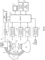
- a rotational x-ray system 28 is illustrated that may be employed for obtaining an angiogram at faster than cardiac rate, such as via fluoroscopic angiography.
- a chemical contrast agent is injected into the patient positioned between an x-ray source and detector, and x-ray projections are captured by the x-ray detector as a two-dimensional image.
- a sequence of two dimensional projection images comprises an angiographic study, with the angiographic image frames acquired at faster than cardiac frequency to allow spatiotemporal reconstruction of the cardiac frequency phenomena into a cardiac space angiogram.
- an example of an angiogram imaging system is shown in the form of a rotational x-ray system 28 including a gantry having a C-arm 30 which carries an x-ray source assembly 32 on one of its ends and an x-ray detector array assembly 34 at its other end.
- the gantry enables the x-ray source 32 and detector 34 to be oriented in different positions and angles around a patient disposed on a table 36, while providing to a physician access to the patient.
- the gantry includes a pedestal 38 which has a horizontal leg 40 that extends beneath the table 36 and a vertical leg 42 that extends upward at the end of the horizontal leg 40 that is spaced apart from table 36.
- a support arm 44 is rotatably fastened to the upper end of vertical leg 42 for rotation about a horizontal pivot axis 46.
- the pivot axis 46 is aligned with the centerline of the table 36, and the arm 44 extends radially outward from the pivot axis 46 to support a C-arm drive assembly 47 on its outer end.
- the C-arm 30 is slidably fastened to the drive assembly 47 and is coupled to a drive motor (not shown) which slides the C-arm 30 to revolve about a C-axis 48 as indicated by arrows 50.
- the pivot axis 46 and C-axis 48 intersect each other, at an isocenter 56 located above the table 36, and are perpendicular to each other.
- the x-ray source assembly 32 is mounted to one end of the C-arm 30 and the detector array assembly 34 is mounted to its other end.
- the x-ray source assembly 32 emits a beam of x-rays which are directed at the detector array assembly 34.
- Both assemblies 32 and 34 extend radially inward to the pivot axis 46 such that the center ray of this beam passes through the system isocenter 56.
- the center ray of the beam thus can be rotated about the system isocenter around either the pivot axis 46 or the C-axis 48, or both, during the acquisition of x-ray attenuation data from a subject placed on the table 36.
- the x-ray source assembly 32 contains an x-ray source which emits a beam of x-rays when energized.
- the center ray passes through the system isocenter 56 and impinges on a two-dimensional flat panel digital detector 58 housed in the detector assembly 34.
- the detector 58 may be, for example, a 2048 x 2048 element two- dimensional array of detector elements. Each element produces an electrical signal that represents the intensity of an impinging x-ray and hence the attenuation of the x-ray as it passes through the patient.
- the x-ray source assembly 32 and detector array assembly 34 are rotated about the system isocenter 56 to acquire x-ray attenuation projection data from different angles.
- the detector array is able to acquire 50 projections, or views, per second which is the limiting factor that determines how many views can be acquired for a prescribed scan path and speed.
- the control mechanism 60 includes an x-ray controller 62 that provides power and timing signals to the x-ray source 52.
- a data acquisition system (DAS) 64 in the control mechanism 60 samples data from detector elements and passes the data to an image reconstructor 65.
- the image reconstructor 65 receives digitized x-ray data from the DAS 64 and performs high speed image reconstruction according to the methods of the present disclosure.
- the reconstructed image is applied as an input to a computer 66 which stores the image in a mass storage device 69 or processes the image further.
- the control mechanism 60 also includes gantry motor controller 67 and a C-axis motor controller 68.
- the motor controllers 67 and 68 provide power to motors in the x-ray system that produce the rotations about respective pivot axis 46 and C-axis 48.
- the computer 66 also receives commands and scanning parameters from an operator via console 70 that has a keyboard and other manually operable controls.
- An associated display 72 allows the operator to observe the reconstructed image and other data from the computer 66.
- the operator supplied commands are used by the computer 66 under the direction of stored programs to provide control signals and information to the DAS 64, the x-ray controller 62 and the motor controllers 67 and 68.
- computer 66 operates a table motor controller 74 which controls the motorized table 36 to position the patient with respect to the system isocenter 56.
- FIG. 2 a block diagram of a computer system or information processing device 80 (e.g., computer 66 in FIG. 1B ) is illustrated that may be incorporated into an angiographic imaging system, such as the rotational x-ray system 28 of FIGs. 1A and 1B , to provide enhanced functionality or used as a standalone device for the extraction of cardiac frequency phenomena from angiographic data according to an embodiment of the present invention.
- computer system 80 includes monitor or display 82, computer 84 (which includes processor(s) 86, bus subsystem 88, memory subsystem 90, and disk subsystem 92), user output devices 94, user input devices 96, and communications interface 98.
- Monitor 82 can include hardware and/or software elements configured to generate visual representations or displays of information. Some examples of monitor 82 may include familiar display devices, such as a television monitor, a cathode ray tube (CRT), a liquid crystal display (LCD), or the like. In some embodiments, monitor 82 may provide an input interface, such as incorporating touch screen technologies.
- monitor 82 may include familiar display devices, such as a television monitor, a cathode ray tube (CRT), a liquid crystal display (LCD), or the like.
- monitor 82 may provide an input interface, such as incorporating touch screen technologies.
- Computer 84 can include familiar computer components, such as one or more central processing units (CPUs), memories or storage devices, graphics processing units (GPUs), communication systems, interface cards, or the like. As shown in FIG. 2 , computer 84 may include one or more processor(s) 86 that communicate with a number of peripheral devices via bus subsystem 88. Processor(s) 86 may include commercially available central processing units or the like. Bus subsystem 88 can include mechanisms for letting the various components and subsystems of computer 84 communicate with each other as intended. Although bus subsystem 88 is shown schematically as a single bus, alternative embodiments of the bus subsystem may utilize multiple bus subsystems. Peripheral devices that communicate with processor(s) 86 may include memory subsystem 90, disk subsystem 92, user output devices 94, user input devices 96, communications interface 98, or the like.
- Memory subsystem 90 and disk subsystem 92 are examples of physical storage media configured to store data.
- Memory subsystem 90 may include a number of memories including random access memory (RAM) for volatile storage of program code, instructions, and data during program execution and read only memory (ROM) in which fixed program code, instructions, and data are stored.
- Disk subsystem 92 may include a number of file storage systems providing persistent (non-volatile) storage for programs and data.
- Other types of physical storage media include floppy disks, removable hard disks, optical storage media such as CD-ROMS, DVDs and bar codes, semiconductor memories such as flash memories, read-only-memories (ROMS), battery-backed volatile memories, networked storage devices, or the like.
- Memory subsystem 90 and disk subsystem 92 may be configured to store programming and data constructs that provide functionality or features of techniques discussed herein.
- Software code modules and/or processor instructions that when executed by processor(s) 86 implement or otherwise provide the functionality may be stored in memory subsystem 90 and disk subsystem 92.
- User input devices 94 can include hardware and/or software elements configured to receive input from a user for processing by components of computer system 80.
- User input devices can include all possible types of devices and mechanisms for inputting information to computer system 84. These may include a keyboard, a keypad, a touch screen, a touch interface incorporated into a display, audio input devices such as microphones and voice recognition systems, and other types of input devices.
- user input devices 94 can be embodied as a computer mouse, a trackball, a track pad, a joystick, a wireless remote, a drawing tablet, a voice command system, an eye tracking system, or the like.
- user input devices 94 are configured to allow a user to select or otherwise interact with objects, icons, text, or the like that may appear on monitor 82 via a command, motions, or gestures, such as a click of a button or the like.
- User output devices 96 can include hardware and/or software elements configured to output information to a user from components of computer system 80.
- User output devices can include all possible types of devices and mechanisms for outputting information from computer 84. These may include a display (e.g., monitor 82), a printer, a touch or force-feedback device, audio output devices, or the like.
- Communications interface 98 can include hardware and/or software elements configured to provide unidirectional or bidirectional communication with other devices.
- communications interface 98 may provide an interface between computer 84 and other communication networks and devices, such as via an internet connection.
- cardiac signals/data may be contemporaneously acquired to serve as a cross correlation target, for purposes of performing the spatiotemporal reconstruction of the vascular pulse waves based on the techniques provided herein.
- the cardiac signals/data may serve as a reference cardiac signal for phase indexing pixels in the angiographic projections.
- FIGs. 3 and 4 illustrate exemplary devices for acquiring/providing a reference cardiac signal with such devices/systems in the form of a pulse oximetry system and/or an echocardiogram (EKG) system or device.
- EKG echocardiogram
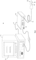
- FIG. 3 is a perspective view of an example of a suitable pulse oximetry system 100 that includes a sensor 102 and a pulse oximetry monitor 104.
- the sensor 102 includes an emitter 106 for emitting light at certain wavelengths into a patient's tissue and a detector 108 for detecting the light after it is reflected and/or absorbed by the patient's tissue.
- the monitor 104 may be capable of calculating physiological characteristics received from the sensor 102 relating to light emission and detection. Further, the monitor 104 includes a display 110 capable of displaying the physiological characteristics and/or other information about the system.
- the sensor 102 is shown communicatively coupled to the monitor 104 via a cable 112, but alternatively may be communicatively coupled via a wireless transmission device or the like.
- the pulse oximetry system 100 also includes a multi-parameter patient monitor 114.
- the multi-parameter patient monitor 114 may be capable of calculating physiological characteristics and providing a central display 116 for information from the monitor 104 and from other medical monitoring devices or systems.
- the multi-parameter patient monitor 114 may display a patient's SpO 2 and pulse rate information from the monitor 104 and blood pressure from a blood pressure monitor on the display 116.
- computer system 80 may be configured to include hardware and software for communicating with a pulse oximetry sensor, such as the sensor 102 shown in FIG. 3 , as well as hardware and software to calculate physiological characteristics received from the pulse oximetry sensor and utilize such characteristics to extract cardiac frequency phenomena, and display the same, in accordance with the techniques described herein.
- FIG. 4 is a schematic diagram of an electrocardiogram ("EKG") device 120 shown optionally connected to an information management system 122 through a communications link 124.
- EKG electrocardiogram
- a commonly used device for acquiring an EKG is a 12-lead electrocardiograph.
- the EKG device 120 and the information management system 122 receives power 126 from an external source.
- the information management system 122 includes a central processing unit 128 connected to a memory unit, or database 130, via a data link 132.
- the CPU 128 processes data and is connected to an output, such as printer 134 and/or display 136.
- the electrocardiogram (EKG) device 120 can be connected directly to a printer 134 or display 136 through communications link 124, if the optional information management system 122 is not utilized.
- the software program according to embodiments provided herein may reside in either the EKG device 120, the information management system 122, or another device associated to receive signals from the EKG device 120.
- the EKG device 120 is connected to a plurality of patient lead wires 138, each having an electrode 140 to receive EKG signals from a patient 142 in a known manner.
- the EKG device 120 has a signal conditioner 144 that receives the EKG signals and filters noise, sets thresholds, segregates signals, and provides the appropriate number of EKG signals for the number of leads 138 to an A/D converter 146 which converts the analog signals to digital signals for processing by a microcontroller 148, or any other type of processing unit.
- Microcontroller 148 is connected to a memory unit 150, similar to memory unit 130, or any other computer readable storage medium.
- computer system 80 may be configured to include hardware and software for communicating with EKG electrodes, such as electrodes 140 shown in FIG. 4 , as well as hardware and software to calculate physiological characteristics received from the electrodes and utilize such characteristics to extract cardiac frequency phenomena, and display the same, in accordance with the techniques described herein.
- present embodiments are directed to systems, methods, and computer readable media for reconstructing cardiac frequency phenomena in angiographic data.
- a sequence of angiographic images i.e., two dimensional projection images
- cardiac rate such as via the system of FIG. 1A , 1B
- analyzed such as via the system of FIG. 2
- a spatiotemporal reconstruction e.g., as described in the '761 patent
- the spatiotemporal reconstructions are complex valued data of the same dimensionality as the projection, and each pixel at each time point has a complex valued datum. It may be represented as a real number and an imaginary number. For physiological interpretation, however, it is represented in polar form with magnitude and a phase. In aspects, the magnitude represents the variation of contrast in a given pixel at cardiac frequency, and the phase represents the phase relative to the cardiac cycle.
- FIGs. 6-9 are flowcharts corresponding to operations of the techniques provided herein. It will be appreciated that the operations described herein may be implemented in an angiographic imaging system or a standalone computer system to improve angiographic image processing and display technologies.
- a cardiac frequency bandpass filter may be applied to the angiographic data taken at greater than cardiac frequency to output the spatiotemporal reconstruction of cardiac frequency angiographic phenomena (e.g., moving vascular pulse waves).
- a cardiac frequency bandpass filter is applied to the angiogram.
- a contemporaneously measured cardiac signal (such as acquired from the pulse oximetry system of FIG. 3 or the electrocardiogram device of FIG. 4 ) may serve as a reference cardiac signal for phase indexing.
- FIG. 6 shows a high level implementation of the techniques provided herein. While the operations are shown separately, it should be understood that certain operations (e.g., temporal processing, bandpass filtering, and amplification) may be combined and/or performed in a different order than as shown in this figure.
- the image is spatially decomposed. In an embodiment, the image may be decomposed into pixels, and subsequent computations performed pixel-wise. In other aspects, pixels may be grouped into different frequency bands, and computation may be performed band-wise.
- temporal processing may be performed to correlate observed intensities of pixels as a function of time to a translational motion signal.
- the translational motion signal may be bandpass filtered, e.g., at cardiac frequency.
- each pixel in an angiographic image may be treated as a separate signal as a function of time, and the cardiac frequency bandpass filter may be applied pixel-wise.
- the cardiac frequency bandpass filter may be applied to groups corresponding to spatial structures.
- a contemporaneously measured cardiac signal (e.g., acquired from the pulse oximetry system of FIG. 3 or the electrocardiogram device of FIG. 4 ) may serve as a cross correlation target, furnishing a type of ultra-narrow bandpass cardiac frequency filter.
- the contemporaneously measured cardiac signal serves as a reference cardiac signal for phase indexing.
- the signal may undergo amplification.
- amplification may be achieved by multiplying the signal by a constant.
- Eulerian magnification may be used.
- the amplification may be performed by isolating and then amplifying the cardiac frequency signal.
- the amplification signal may be recombined with the original signal, for example, by aligning the amplified signal with the original signal (e.g., based on time varying intensities, based on a timestamp, etc.).
- the amplified signal may be additively combined to the original signal.
- the amplified signal may be superimposed onto the original signal.
- the original signal may be combined or superimposed with the amplified bandpass signal to form a reconstructed signal.
- the reconstructed signal may undergo noise suppression (e.g., bilateral filtering or other suitable technique).
- noise suppression e.g., bilateral filtering or other suitable technique.
- the cardiac frequency bandpass filter may be real valued or complex valued, according to embodiments. If the cardiac frequency bandpass filter is real valued, then the resulting cardiac frequency phenomena will be reevaluated, and may be rendered in image form using any suitable visualization format including grayscale, colorscale, and/or brightness. Alternately, if the cardiac frequency bandpass filter is complex valued, having a real component and an imaginary component, it may be represented in a polar form comprising a magnitude and a phase. After passage through a cardiac frequency bandpass filter, the magnitude may be interpreted as cardiac frequency magnitude, as in a "strength of the heart action." The phase may be interpreted as the temporal location within a cardiac cycle. The magnitude and the phase may be rendered using a brightness-hue color model, where the brightness of a pixel represents a cardiac frequency magnitude and the hue represents a cardiac frequency phase.
- the cardiac frequency bandpass filter and amplified images may be rendered in gray scale or in a color scale (referring back to FIG. 5 ), where optionally color brightness may represent cardiac frequency magnitude or spatial motion speed, and color hue may represent cardiac frequency phase or spatial motion direction, depending on the user's choice of whether to emphasize the temporal or spatial properties in the cardiac frequency band of the reconstructed result.
- color brightness may represent cardiac frequency magnitude or spatial motion speed
- color hue may represent cardiac frequency phase or spatial motion direction, depending on the user's choice of whether to emphasize the temporal or spatial properties in the cardiac frequency band of the reconstructed result.
- the image is submitted as grayscale, one of ordinary skill in the art would recognize that this grayscale image includes a spectrum of hues.
- the color model for rendering a complex valued number in a pixel is depicted in FIG. 5, and FIG. 5 may show a spectrum of color hues including a green region, a yellow region, a red region, and a blue region.
- a sequence of such images may be animated across the time indices to
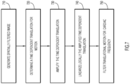
- FIG. 7 an example is provided hereinbelow for a given spatially filtered image and for only one spatial dimension, x, and the time t dimension, t, for purposes of illustration.
- This representation corresponds to a continuous form of signals.
- these continuous equations may be applied to process digitized images, according to techniques known in the art.
- a spatially filtered image is generated.
- An image I(x,t) may undergo spatial decomposition, as provided herein.
- spatial decomposition may include pyramidal decomposition, in which coarse filtering is used to separate regions into different frequency bands and fine filtering is used to refine the image.
- higher order terms e.g., second order, third order, etc.
- This equation corresponds to the reconstructed signal including the amplified time dependent translation.
- the term ⁇ (t) ⁇ f(x) / ⁇ x acts as a cardiac frequency bandpass filter (with time windowing) such that its value is zero for temporal phenomena outside of the cardiac frequency band.
- the time dependent translation is amplified by (1+ ⁇ ) (if ⁇ is chosen to be greater than zero) and combined with the original image f(x).
- This reconstruction may be shown as a cine video sequence to illustrate the spatiotemporal angiographic phenomena.
- the images may be synthesized from their pyramids of spatially decomposed images.
- amplification techniques may be optional, and only bandpass filtering may be performed.
- a Fourier transform may act as a bandpass filter.
- a spatial decomposition is performed on the image.
- the image may be subjected to a cardiac scale bandpass filter and then pixel-wise transformed into the frequency domain using a Fourier transform.
- a time windowed Fourier transform may be applied.
- the cardiac scale may be amplified in the frequency domain.
- the amplified frequency domain image may be inverse transformed into the time domain, and the spatiotemporal angiographic phenomena with an amplified cardiac range may be displayed.
- Eulerian magnification techniques may be modified and extended to allow for custom amplification of the cardiac angiographic phenomena.
- present approaches extend these techniques to an angiogram, comprising a temporal sequence of images obtained during the passage of an intravascularly injected contrast bolus into the vasculature at faster than cardiac frequency.
- the amplification factor ⁇ may be selected to amplify spatiotemporal angiographic phenomenon, allowing for reproducibility by restricting and standardizing ranges for this factor.
- amplification may be performed using Eulerian magnification methods.
- a spatial filter is applied to a temporally arranged sequence of two or more images.
- a temporal filter is applied to the plurality of results of the spatial filter.
- One or more of the dual spatial and temporal filtered results are selectively amplified, and then reassembled into a sequence of images in order to yield an amplified effect corresponding to reconstruction of spatiotemporal phenomena.
- These techniques may be applied to angiographic images in order to select for those with temporal and spatial phenomena of interest, including temporal phenomena corresponding to the cardiac frequency phenomena.
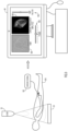
- FIG. 9 An example implementation is provided in FIG. 9 .
- a bandpass filter is applied with an amplification factor to visualize the cardiac frequency phenomena.
- the left hand portion of the diagram shows a patient 910 undergoing an angiogram simultaneous with a cardiac signal being recorded from a finger pulse oximeter 102 (also known as optical plethysmogram).
- the angiogram is obtained by injecting a bolus of contrast into the patient and acquiring angiographic images at faster than cardiac frequency.
- the cardiac frequency may be obtained from the patient's cardiac signal.
- the cardiac signal may vary as a function of time. In this case, the momentary cardiac signal may be referenced with respect to corresponding obtained images.
- a graphical user interface is shown with two main display elements 920 and 930 and two visual control widgets 940 and 945. It will be appreciated that the graphical user interface could be displayed on a computer monitor, such as the monitor of computer system 80.
- the two main display elements are a cardiac angiogram image 920 without cardiac frequency amplification (left on the computer monitor, labeled "Raw") and a cardiac angiogram image 930 with cardiac frequency amplification (right on the computer monitor, labeled "Cardiac Frequency Amplified," with the brightness-hue model for cardiac frequency magnitude and phase).
- Other display methods including but not limited to grayscale, monochrome, etc. are contemplated for use with present techniques.
- a horizontally oriented slider control widget 940 (labeled "Frame"), positioned below the images, may be moved left and right on the screen by a user (e.g., by dragging with a mouse) to control the image frame being displayed.
- a cardiac frequency filter (as described in FIGs. 6-8 ) is applied to all image frames of the angiographic image sequence, and a clinician or radiologist may inspect one frame at a time.
- a 3D rendering of the cardiac frequency-amplified image is provided, e.g., using the techniques described in co-pending U.S. Patent Application, Ser. No. 16/784,125 filed on February 6, 2020 .
- the graphical user interface also includes a vertically oriented slider control 945 on the right (labeled "Amp Factor") that can be adjusted by a user (e.g., by dragging with a mouse) to specify the degree of amplification of cardiac frequency.
- Amp Factor a vertically oriented slider control 945 on the right
- users who are interpreting the images may modify the amplification and spatial resolution of the images based on the techniques provided herein, to customize these settings for specific medical analysis. These techniques may provide medical insight into cardiac frequency activity transpiring in the subject being imaged.
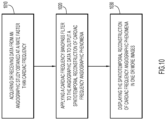
- FIG. 10 shows high level operations of the techniques provided herein.
- data is acquired or received from an angiographic study obtained at a rate faster than cardiac frequency.
- a cardiac frequency bandpass filter is applied to the angiographic data to output a spatiotemporal reconstruction of cardiac frequency angiographic phenomena.
- the spatiotemporal reconstruction of cardiac frequency angiographic phenomena in one or more images is displayed.
- embodiments provided herein include a system, method, and computer readable media for spatiotemporally reconstructing cardiac frequency phenomena in angiographic data that apply a cardiac frequency bandpass filter to angiographic data, with or without a Eulerian magnification, for extracting and potentially magnifying cardiac frequency phenomena.
- these techniques may be combined with the techniques provided in the '761 patent to further magnify cardiac frequency phenomena.
- These techniques may be applied with a hardware system designed to obtain angiographic images, and in particular an angiographic system, to obtain images for a patient.
- These techniques provide an improvement in the art over existing angiographic approaches, namely, allowing the spatiotemporal cardiac frequency phenomenon to be amplified an superimposed on the angiographic signal.
- This enhancement may allow improved visualization by amplification of vascular pulse waves as well as resolution of fine detail (based on spatial filtering techniques), as compared to existing techniques.
- amplification may be custom controlled as described in herein to allow varying degrees of amplification and resolution, which may be customized to yield information for various medical analysis.
Landscapes
- Health & Medical Sciences (AREA)
- Engineering & Computer Science (AREA)
- Life Sciences & Earth Sciences (AREA)
- Medical Informatics (AREA)
- Physics & Mathematics (AREA)
- Radiology & Medical Imaging (AREA)
- General Health & Medical Sciences (AREA)
- Nuclear Medicine, Radiotherapy & Molecular Imaging (AREA)
- High Energy & Nuclear Physics (AREA)
- Biomedical Technology (AREA)
- Veterinary Medicine (AREA)
- Public Health (AREA)
- Animal Behavior & Ethology (AREA)
- Biophysics (AREA)
- Surgery (AREA)
- Optics & Photonics (AREA)
- Pathology (AREA)
- Molecular Biology (AREA)
- Heart & Thoracic Surgery (AREA)
- Computer Vision & Pattern Recognition (AREA)
- Physiology (AREA)
- Theoretical Computer Science (AREA)
- General Physics & Mathematics (AREA)
- Oral & Maxillofacial Surgery (AREA)
- Vascular Medicine (AREA)
- Dentistry (AREA)
- Quality & Reliability (AREA)
- Human Computer Interaction (AREA)
- Apparatus For Radiation Diagnosis (AREA)
- Algebra (AREA)
- Mathematical Analysis (AREA)
- Mathematical Optimization (AREA)
- Mathematical Physics (AREA)
- Pure & Applied Mathematics (AREA)
- Image Processing (AREA)
- Image Analysis (AREA)
Claims (15)
- Un procédé d'extraction de phénomènes angiographiques de fréquence cardiaque à partir d'une étude angiographique obtenue à une cadence supérieure à la fréquence cardiaque, le procédé comprenant :l'acquisition ou la réception (1010) de données en provenance d'une étude angiographique obtenue à une cadence supérieure à la fréquence cardiaque ;l'acquisition d'un signal cardiaque concomitamment mesuré qui varie en fonction du temps ;l'obtention, à partir du signal cardiaque concomitamment mesuré, d'une fréquence cardiaque momentanée ;l'utilisation de la fréquence cardiaque en tant que cible d'intercorrélation pour produire un filtre passe-bande de fréquence cardiaque dont la plage est limitée par la fréquence cardiaque ;l'application (1020) du filtre passe-bande de fréquence cardiaque aux données angiographiques pour générer une reconstruction spatiotemporelle de phénomènes angiographiques de fréquence cardiaque sans utilisation d'ondelettes ; etl'affichage (1030) de la reconstruction spatiotemporelle des phénomènes angiographiques de fréquence cardiaque en une ou plusieurs images.
- Le procédé de la revendication 1, comprenant en outre l'application d'un grossissement eulérien, comprenant :l'application d'une décomposition spatiale à une séquence d'images angiographiques ;l'application d'un filtre temporel à la séquence spatialement décomposée d'images angiographiques ;le grossissement sélectif d'une ou plusieurs des images angiographiques de la séquence doublement spatialement décomposée et temporellement filtrée d'images angiographiques ; etle réassemblage de la séquence sélectivement grossie d'images angiographiques avec la séquence d'images angiographiques en une séquence combinée d'images angiographiques pour permettre la visualisation d'une reconstruction spatiotemporelle amplifiée.
- Le procédé de la revendication 2, dans lequel l'application de la décomposition spatiale comprend en outre l'exécution d'un filtrage anisotrope multi-échelle ou l'application d'une transformation spatiale comprenant l'une d'entre des shearlets ou des ridgelets.
- Le procédé de la revendication 2, comprenant en outre la sélection d'images angiographiques avec des phénomènes temporels et spatiaux d'intérêt, comprenant des phénomènes temporels correspondant à une bande de fréquences cardiaques.
- Le procédé de la revendication 2, dans lequel l'application de la décomposition spatiale comprend l'exécution d'une décomposition spatiale d'une image angiographique en plusieurs images avec chacune des caractéristiques spatiales différentes, comprenant le filtrage pour des structures spatiales de fréquences spatiales spécifiques.
- Le procédé de la revendication 2, dans lequel le filtre passe-bande de fréquence cardiaque est appliqué avec une valeur de zéro pour des phénomènes temporels en dehors d'une bande de fréquences cardiaques, et comprenant en outre :la reconstruction d'images angiographiques comprenant les phénomènes de fréquence cardiaque avec des translations spatiales grossies.
- Le procédé de la revendication 6, dans lequel les images angiographiques reconstruites sont délivrées sous forme d'une séquence vidéo animée.
- Un système angiographique pour l'extraction de phénomènes angiographiques de fréquence cardiaque obtenus à une cadence supérieure à la fréquence cardiaque, le système angiographique comprenant :une source de rayons X (32) et un détecteur de rayons X (34) pour l'obtention de données angiographiques ;un ou plusieurs processeurs de calculateur (86) ;un ou plusieurs supports de stockage lisibles par calculateur ; etdes instructions de programme stockées sur les un ou plusieurs supports de stockage lisibles par calculateur pour exécution par au moins l'un des un ou plusieurs processeurs de calculateur, les instructions de programme comprenant des instructions pour :acquérir ou recevoir (1010) des données en provenance d'une étude angiographique obtenue à une cadence supérieure à la fréquence cardiaque ;acquérir un signal cardiaque concomitamment mesuré qui varie en fonction du temps ;obtenir, à partir du signal cardiaque concomitamment mesuré, une fréquence cardiaque momentanée ;utiliser la fréquence cardiaque en tant que cible d'intercorrélation pour produire un filtre passe-bande de fréquence cardiaque dont la plage est limitée par la fréquence cardiaque ;appliquer (1020) le filtre passe-bande de fréquence cardiaque aux données angiographiques pour générer une reconstruction spatiotemporelle de phénomènes angiographiques de fréquence cardiaque sans utilisation d'ondelettes ; etafficher (1030) la reconstruction spatiotemporelle des phénomènes angiographiques de fréquence cardiaque en une ou plusieurs images.
- Le système de la revendication 8, dans lequel les instructions de programme comprennent en outre des instructions pour appliquer un grossissement eulérien aux données angiographiques, comprenant des instructions pour :appliquer une décomposition spatiale à une séquence d'images angiographiques ;appliquer un filtre temporel à la séquence spatialement décomposée d'images angiographiques ;grossir sélectivement une ou plusieurs des images angiographiques de la séquence doublement spatialement décomposée et temporellement filtrée d'images angiographiques ; etréassembler la séquence sélectivement grossie d'images angiographiques avec la séquence d'images angiographiques en une séquence combinée d'images angiographiques pour permettre la visualisation d'une reconstruction spatiotemporelle amplifiée.
- Le système de la revendication 9, dans lequel les instructions de programme comprennent en outre des instructions pour exécuter un filtrage anisotrope multi-échelle ou appliquer une transformation spatiale comprenant l'une d'entre des shearlets ou des ridgelets.
- Le système de la revendication 9, dans lequel les instructions de programme comprennent en outre des instructions pour :
sélectionner des images angiographiques avec des phénomènes temporels et spatiaux d'intérêt, comprenant des phénomènes temporels correspondant à une bande de fréquences cardiaques. - Le système de la revendication 9, dans lequel les instructions de programme comprennent en outre des instructions pour :
exécuter une décomposition spatiale d'une image angiographique en plusieurs images avec chacune des caractéristiques spatiales différentes, comprenant le filtrage pour des structures spatiales de fréquences spatiales spécifiques. - Le système de la revendication 9, dans lequel le filtre passe-bande de fréquence cardiaque est appliqué avec une valeur de zéro pour des phénomènes temporels en dehors d'une bande de fréquences cardiaques, et dans lequel les instructions de programme comprennent en outre des instructions pour :
reconstruire des images angiographiques comprenant les phénomènes de fréquence cardiaque avec des translations spatiales grossies. - Un programme de calculateur comprenant des instructions qui, lorsque le programme est exécuté par un calculateur, font en sorte que le calculateur mette en œuvre le procédé de l'une des revendications 1 à 7.
- Le programme de calculateur de la revendication 14, dans lequel les instructions, lorsque le programme est exécuté par le calculateur, font en outre en sorte que le calculateur :applique un grossissement eulérien aux données angiographiques ;applique une décomposition spatiale à une séquence d'images angiographiques ;applique un filtre temporel à la séquence spatialement décomposée d'images angiographiques ;grossisse sélectivement une ou plusieurs des images angiographiques de la séquence doublement spatialement décomposée et temporellement filtrée d'images angiographiques ; etréassemble la séquence sélectivement grossie d'images angiographiques avec la séquence d'images angiographiques en une séquence combinée d'images angiographiques pour permettre la visualisation d'une reconstruction spatiotemporelle amplifiée.
Applications Claiming Priority (2)
| Application Number | Priority Date | Filing Date | Title |
|---|---|---|---|
| US201962824582P | 2019-03-27 | 2019-03-27 | |
| PCT/US2020/025229 WO2020198592A1 (fr) | 2019-03-27 | 2020-03-27 | Reconstruction de phénomènes de fréquence cardiaque dans des données angiographiques |
Publications (3)
| Publication Number | Publication Date |
|---|---|
| EP3927237A1 EP3927237A1 (fr) | 2021-12-29 |
| EP3927237A4 EP3927237A4 (fr) | 2022-11-23 |
| EP3927237B1 true EP3927237B1 (fr) | 2025-04-30 |
Family
ID=72607660
Family Applications (1)
| Application Number | Title | Priority Date | Filing Date |
|---|---|---|---|
| EP20777422.5A Active EP3927237B1 (fr) | 2019-03-27 | 2020-03-27 | Reconstruction de phénomènes de fréquence cardiaque dans des données angiographiques |
Country Status (10)
| Country | Link |
|---|---|
| US (1) | US11291422B2 (fr) |
| EP (1) | EP3927237B1 (fr) |
| JP (1) | JP7490002B2 (fr) |
| KR (1) | KR102722504B1 (fr) |
| CN (1) | CN113677272B (fr) |
| AU (1) | AU2020244866B2 (fr) |
| CA (1) | CA3131140C (fr) |
| ES (1) | ES3036845T3 (fr) |
| GB (1) | GB2596015B (fr) |
| WO (1) | WO2020198592A1 (fr) |
Families Citing this family (5)
| Publication number | Priority date | Publication date | Assignee | Title |
|---|---|---|---|---|
| JP7304418B2 (ja) | 2019-02-06 | 2023-07-06 | ウィリアム イー バトラー, | 複数の低次元血管造影投影からの移動血管脈波の時空間的再構成 |
| JP7357060B2 (ja) | 2019-02-06 | 2023-10-05 | ウィリアム イー バトラー, | 血管造影の改善された方法 |
| EP3927237B1 (fr) | 2019-03-27 | 2025-04-30 | William E. Butler | Reconstruction de phénomènes de fréquence cardiaque dans des données angiographiques |
| ES3033066T3 (en) | 2019-04-04 | 2025-07-30 | William E Butler | Intrinsic contrast optical cross-correlated wavelet angiography |
| US12220272B2 (en) | 2021-05-12 | 2025-02-11 | Angiowave Imaging, Inc. | Motion-compensated wavelet angiography |
Family Cites Families (86)
| Publication number | Priority date | Publication date | Assignee | Title |
|---|---|---|---|---|
| US3335716A (en) | 1965-01-18 | 1967-08-15 | Gen Electric | Diagnostic thermography method and means |
| US5637871A (en) | 1993-06-07 | 1997-06-10 | Computational Systems, Inc. | Portable digital infrared thermography system |
| US6195456B1 (en) | 1996-12-19 | 2001-02-27 | Xerox Corporation | Multi resolution color correction using wavelet transforms |
| US5963676A (en) | 1997-02-07 | 1999-10-05 | Siemens Corporate Research, Inc. | Multiscale adaptive system for enhancement of an image in X-ray angiography |
| JP4127889B2 (ja) | 1998-03-04 | 2008-07-30 | 株式会社日立メディコ | 磁気共鳴イメージング装置 |
| US6549801B1 (en) | 1998-06-11 | 2003-04-15 | The Regents Of The University Of California | Phase-resolved optical coherence tomography and optical doppler tomography for imaging fluid flow in tissue with fast scanning speed and high velocity sensitivity |
| ATE506005T1 (de) | 1999-09-24 | 2011-05-15 | Ca Nat Research Council | Vorrichtung zur durchführung einer intraoperativen angiographie |
| US6985632B2 (en) | 2000-04-17 | 2006-01-10 | Canon Kabushiki Kaisha | Image processing system, image processing apparatus, and image processing method |
| US6975753B2 (en) | 2000-09-13 | 2005-12-13 | Canon Kabushiki Kaisha | Image processing apparatus, image processing method, program for implementing said method, and storage medium therefor |
| US7031504B1 (en) | 2000-09-26 | 2006-04-18 | Vital Images, Inc. | Image data based retrospective temporal selection of medical images |
| EP2465419B1 (fr) | 2001-06-22 | 2015-08-05 | Nellcor Puritan Bennett Ireland | Analyse à base d'ondelettes de signaux d'oxymétrie de pouls |
| US6761878B2 (en) | 2001-10-17 | 2004-07-13 | Mallinckrodt, Inc. | Pathological tissue detection and treatment employing targeted benzoindole optical agents |
| US7020314B1 (en) | 2001-11-13 | 2006-03-28 | Koninklijke Philips Electronics N.V. | Black blood angiography method and apparatus |
| US6842638B1 (en) | 2001-11-13 | 2005-01-11 | Koninklijke Philips Electronics N.V. | Angiography method and apparatus |
| US6891918B2 (en) | 2002-11-27 | 2005-05-10 | Ge Medical Systems Global Technology Company, Llc | Methods and apparatus for acquiring perfusion data |
| US7697974B2 (en) | 2003-10-10 | 2010-04-13 | Ge Medical Systems Global Technology Company, Llc | Methods and apparatus for analysis of angiographic and other cyclical images |
| US7220230B2 (en) * | 2003-12-05 | 2007-05-22 | Edwards Lifesciences Corporation | Pressure-based system and method for determining cardiac stroke volume |
| US7359062B2 (en) | 2003-12-09 | 2008-04-15 | The Regents Of The University Of California | High speed spectral domain functional optical coherence tomography and optical doppler tomography for in vivo blood flow dynamics and tissue structure |
| US7672706B2 (en) | 2004-08-23 | 2010-03-02 | Boston Scientific Scimed, Inc. | Systems and methods for measuring pulse wave velocity with an intravascular device |
| US8411915B2 (en) | 2005-08-04 | 2013-04-02 | Koninklijke Philips Electronics N.V. | Motion compensation in functional imaging |
| WO2007037937A1 (fr) | 2005-09-22 | 2007-04-05 | Wisconsin Alumni Research Foundation | Reconstruction d’images des battements du coeur à l’aide d’une projection arrière hautement contrainte |
| US7918793B2 (en) | 2005-10-28 | 2011-04-05 | Biosense Webster, Inc. | Synchronization of ultrasound imaging data with electrical mapping |
| US20070185393A1 (en) | 2006-02-03 | 2007-08-09 | Triage Wireless, Inc. | System for measuring vital signs using an optical module featuring a green light source |
| US8360986B2 (en) | 2006-06-30 | 2013-01-29 | University Of Louisville Research Foundation, Inc. | Non-contact and passive measurement of arterial pulse through thermal IR imaging, and analysis of thermal IR imagery |
| US7602183B2 (en) | 2007-02-13 | 2009-10-13 | The Board Of Trustees Of The Leland Stanford Junior University | K-T sparse: high frame-rate dynamic magnetic resonance imaging exploiting spatio-temporal sparsity |
| WO2008124845A2 (fr) | 2007-04-10 | 2008-10-16 | University Of Southern California | Procédés et systèmes pour la mesure du flux sanguin utilisant la tomographie à cohérence optique doppler |
| DE102007061935A1 (de) | 2007-12-21 | 2009-06-25 | Siemens Aktiengesellschaft | Verfahren zur Qualitätssteigerung von computertomographischen Aufnahmeserien durch Bildverarbeitung und CT-System mit Recheneinheit |
| WO2010018495A1 (fr) * | 2008-08-13 | 2010-02-18 | Koninklijke Philips Electronics N.V. | Imagerie doppler couleur en radiographie |
| DE102008048045A1 (de) | 2008-09-19 | 2010-04-01 | Siemens Aktiengesellschaft | Verfahren zur Erzeugung von computertomographischen Bilddatensätzen eines Patienten in der Herz-CT bei einer Perfusionskontrolle unter Kontrastmittelapplikation |
| JP5911726B2 (ja) | 2008-11-10 | 2016-04-27 | カーディオインサイト テクノロジーズ インコーポレイテッド | 電気生理学データの視覚化 |
| JP5402056B2 (ja) * | 2009-02-16 | 2014-01-29 | コニカミノルタ株式会社 | 画像処理装置、画像処理方法、およびプログラム |
| US9019305B2 (en) | 2009-04-10 | 2015-04-28 | Siemens Medical Solutions Usa, Inc. | Method of visualization of contrast intensity change over time in a DSA image |
| WO2010121003A1 (fr) | 2009-04-16 | 2010-10-21 | Mallinckrodt Inc. | Dérivés de pyrazine pour imagerie optique et thérapie |
| US8855749B2 (en) | 2009-09-24 | 2014-10-07 | Covidien Lp | Determination of a physiological parameter |
| US8605976B2 (en) | 2009-12-10 | 2013-12-10 | General Electric Corporation | System and method of detection of optimal angiography frames for quantitative coronary analysis using wavelet-based motion analysis |
| US10478076B2 (en) * | 2009-12-28 | 2019-11-19 | Gambro Lundia Ab | Monitoring a property of the cardiovascular system of a subject |
| RU2434288C1 (ru) | 2010-06-08 | 2011-11-20 | Закрытое Акционерное Общество "Импульс" | Способ коррекции цифровых изображений |
| US8559692B2 (en) | 2010-06-08 | 2013-10-15 | Zakrytoe akcionernoe obshchestvo “Impul's” | Method for correction of digital images |
| BR112012033776A2 (pt) | 2010-07-12 | 2016-11-01 | Ge Healthcare As | composição,e, método de exame de raios-x. |
| KR101689867B1 (ko) | 2010-09-15 | 2016-12-27 | 삼성전자주식회사 | 영상을 처리하는 방법, 이를 수행하는 영상처리장치 및 의료영상시스템 |
| US8520924B2 (en) | 2010-11-03 | 2013-08-27 | Siemens Corporation | Spatio-temporal analysis for automatic contrast injection detection on angiography during trans-catheter aortic valve implantation |
| WO2012073140A1 (fr) | 2010-12-01 | 2012-06-07 | Koninklijke Philips Electronics N.V. | Dispositif d'amélioration de rapport contraste sur bruit (cnr) |
| KR101820844B1 (ko) | 2011-07-22 | 2018-01-23 | 삼성전자주식회사 | 진단영상 생성장치, 의료영상시스템 및 이미지를 처리하는 방법 |
| US8849005B2 (en) * | 2011-09-28 | 2014-09-30 | Siemens Aktiengesellschaft | Coronary artery motion modeling |
| US8948480B2 (en) | 2011-11-10 | 2015-02-03 | Siemens Aktiengesellschaft | Image reconstruction using redundant Haar wavelets |
| CN107982550A (zh) | 2012-01-11 | 2018-05-04 | 通用电气医疗集团股份有限公司 | 具有低碘浓度的x-射线成像造影介质和x-射线成像方法 |
| JP5849791B2 (ja) * | 2012-03-14 | 2016-02-03 | 株式会社島津製作所 | 画像処理装置 |
| DE102012205935B4 (de) | 2012-04-12 | 2018-11-15 | Siemens Healthcare Gmbh | Verfahren zur Aufnahme eines vierdimensionalen Angiographie-Datensatzes |
| US9357916B2 (en) | 2012-05-10 | 2016-06-07 | Carl Zeiss Meditec, Inc. | Analysis and visualization of OCT angiography data |
| US9345413B2 (en) | 2012-08-12 | 2016-05-24 | David Schie | Heart rate extraction using neural wavelet adaptive gain control and neural pattern processing |
| DE102012214351B4 (de) * | 2012-08-13 | 2014-11-06 | Siemens Aktiengesellschaft | Angiographisches Untersuchungsverfahren eines Gefäßsystems |
| US9324005B2 (en) | 2012-09-07 | 2016-04-26 | Massachusetts Institute of Technology Quanta Computer Inc. | Complex-valued phase-based eulerian motion modulation |
| US9811901B2 (en) | 2012-09-07 | 2017-11-07 | Massachusetts Institute Of Technology | Linear-based Eulerian motion modulation |
| US9805475B2 (en) | 2012-09-07 | 2017-10-31 | Massachusetts Institute Of Technology | Eulerian motion modulation |
| US9254093B2 (en) * | 2013-01-16 | 2016-02-09 | University Of Vermont | Methods and systems for minimizing and treating cardiac fibrillation |
| CN103126655B (zh) * | 2013-03-14 | 2014-10-08 | 浙江大学 | 一种非约束目标的非接触式脉搏波采集系统及采集方法 |
| WO2015044366A1 (fr) | 2013-09-30 | 2015-04-02 | Carl Zeiss Meditec Ag | Imagerie oct doppler de l'écoulement sanguin rétinien à haute résolution temporelle |
| US9504426B2 (en) * | 2013-12-06 | 2016-11-29 | Xerox Corporation | Using an adaptive band-pass filter to compensate for motion induced artifacts in a physiological signal extracted from video |
| CN103767694B (zh) * | 2014-01-06 | 2015-07-08 | 西安交通大学 | 一种准确提取袖带压力震荡波的方法 |
| US20150257653A1 (en) * | 2014-03-14 | 2015-09-17 | Elwha Llc | Device, system, and method for determining blood pressure in a mammalian subject |
| US20160135775A1 (en) | 2014-11-17 | 2016-05-19 | Wisconsin Alumni Research Foundation | System And Method For Time-Resolved, Three-Dimensional Angiography With Physiological Information |
| US20160189394A1 (en) | 2014-12-30 | 2016-06-30 | Huazhong University Of Science And Technology | Method for iteratively extracting motion parameters from angiography images |
| US9836849B2 (en) | 2015-01-28 | 2017-12-05 | University Of Florida Research Foundation, Inc. | Method for the autonomous image segmentation of flow systems |
| US10758122B2 (en) | 2015-02-06 | 2020-09-01 | Richard F. Spaide | Volume analysis and display of information in optical coherence tomography angiography |
| US9713424B2 (en) | 2015-02-06 | 2017-07-25 | Richard F. Spaide | Volume analysis and display of information in optical coherence tomography angiography |
| US10818073B2 (en) | 2015-03-10 | 2020-10-27 | Wisconsin Alumni Research Foundation | System and method for time-resolved, three-dimensional angiography with flow information |
| JP6348865B2 (ja) * | 2015-03-30 | 2018-06-27 | 株式会社リガク | Ct画像処理装置および方法 |
| US10132902B2 (en) | 2015-05-26 | 2018-11-20 | The Board Of Trustees Of The Leland Stanford Junior University | Intrinsic navigation from velocity-encoding gradients in phase-contrast MRI |
| US10123761B2 (en) * | 2015-07-01 | 2018-11-13 | William E. Butler | Device and method for spatiotemporal reconstruction of a moving vascular pulse wave in the brain and other organs |
| CN108348179B (zh) * | 2015-11-03 | 2021-04-13 | 弗雷塞尼斯医疗保健控股公司 | 通过视频成像处理评估血液透析患者内的通路流量的方法和设备 |
| JP7090546B2 (ja) * | 2015-12-21 | 2022-06-24 | ザ リージェンツ オブ ザ ユニバーシティ オブ カリフォルニア | 灌流デジタルサブトラクション血管造影 |
| WO2017146886A1 (fr) | 2016-02-23 | 2017-08-31 | Mayo Foundation For Medical Education And Research | Imagerie du débit sanguin par ultrasons |
| JP6701880B2 (ja) | 2016-03-30 | 2020-05-27 | コニカミノルタ株式会社 | 動態解析装置、動態解析システム、動態解析方法及びプログラム |
| DE102016215971A1 (de) | 2016-08-25 | 2018-03-01 | Siemens Healthcare Gmbh | Segmentierung einer Angiographie unter Verwendung einer bestehenden dreidimensionalen Rekonstruktion |
| JP6783619B2 (ja) * | 2016-10-20 | 2020-11-11 | 株式会社日立製作所 | 磁気共鳴イメージング装置及び画像解析方法 |
| CN107529646B (zh) * | 2017-05-02 | 2021-01-26 | 广东工业大学 | 一种基于欧拉影像放大的无接触式心率测量方法及装置 |
| WO2018210693A1 (fr) * | 2017-05-15 | 2018-11-22 | Smith & Nephew Plc | Système de thérapie de plaie par pression négative utilisant un grossissement vidéo eulérien |
| US11801114B2 (en) | 2017-09-11 | 2023-10-31 | Philipp K. Lang | Augmented reality display for vascular and other interventions, compensation for cardiac and respiratory motion |
| US11202589B2 (en) * | 2017-11-30 | 2021-12-21 | University Of Kentucky Research Foundation | System and method for assessment of retinal and choroidal blood flow noninvasively using color amplification |
| CN109044314B (zh) * | 2018-06-15 | 2021-06-08 | 西安电子科技大学 | 一种基于欧拉视频放大的非接触式心率监测方法 |
| US10783632B2 (en) | 2018-12-14 | 2020-09-22 | Spectral Md, Inc. | Machine learning systems and method for assessment, healing prediction, and treatment of wounds |
| JP7304418B2 (ja) | 2019-02-06 | 2023-07-06 | ウィリアム イー バトラー, | 複数の低次元血管造影投影からの移動血管脈波の時空間的再構成 |
| JP7357060B2 (ja) | 2019-02-06 | 2023-10-05 | ウィリアム イー バトラー, | 血管造影の改善された方法 |
| JP7360470B2 (ja) | 2019-03-08 | 2023-10-12 | ウィリアム イー バトラー, | 血管造影撮像システムの時間的較正 |
| EP3927237B1 (fr) | 2019-03-27 | 2025-04-30 | William E. Butler | Reconstruction de phénomènes de fréquence cardiaque dans des données angiographiques |
| ES3033066T3 (en) | 2019-04-04 | 2025-07-30 | William E Butler | Intrinsic contrast optical cross-correlated wavelet angiography |
-
2020
- 2020-03-27 EP EP20777422.5A patent/EP3927237B1/fr active Active
- 2020-03-27 JP JP2021557091A patent/JP7490002B2/ja active Active
- 2020-03-27 CA CA3131140A patent/CA3131140C/fr active Active
- 2020-03-27 WO PCT/US2020/025229 patent/WO2020198592A1/fr not_active Ceased
- 2020-03-27 US US16/832,695 patent/US11291422B2/en active Active
- 2020-03-27 CN CN202080024265.9A patent/CN113677272B/zh active Active
- 2020-03-27 AU AU2020244866A patent/AU2020244866B2/en active Active
- 2020-03-27 KR KR1020217030804A patent/KR102722504B1/ko active Active
- 2020-03-27 ES ES20777422T patent/ES3036845T3/es active Active
- 2020-03-27 GB GB2113127.1A patent/GB2596015B/en active Active
Also Published As
| Publication number | Publication date |
|---|---|
| CA3131140C (fr) | 2024-04-30 |
| GB2596015B (en) | 2022-10-12 |
| US20200305822A1 (en) | 2020-10-01 |
| GB202113127D0 (en) | 2021-10-27 |
| CA3131140A1 (fr) | 2020-10-01 |
| EP3927237A4 (fr) | 2022-11-23 |
| JP2022527153A (ja) | 2022-05-31 |
| GB2596015A (en) | 2021-12-15 |
| AU2020244866B2 (en) | 2025-11-20 |
| ES3036845T3 (en) | 2025-09-24 |
| KR102722504B1 (ko) | 2024-10-29 |
| JP7490002B2 (ja) | 2024-05-24 |
| CN113677272B (zh) | 2023-11-24 |
| AU2020244866A1 (en) | 2021-10-14 |
| WO2020198592A1 (fr) | 2020-10-01 |
| KR20210130785A (ko) | 2021-11-01 |
| US11291422B2 (en) | 2022-04-05 |
| EP3927237A1 (fr) | 2021-12-29 |
| CN113677272A (zh) | 2021-11-19 |
Similar Documents
| Publication | Publication Date | Title |
|---|---|---|
| EP3927237B1 (fr) | Reconstruction de phénomènes de fréquence cardiaque dans des données angiographiques | |
| KR101604812B1 (ko) | 의료 영상 처리 장치 및 그에 따른 의료 영상 처리 방법 | |
| US7209779B2 (en) | Methods and software for retrospectively gating a set of images | |
| US20030016782A1 (en) | Graphical user interfaces and methods for retrospectively gating a set of images | |
| US11510642B2 (en) | Spatiotemporal reconstruction in higher dimensions of a moving vascular pulse wave from a plurality of lower dimensional angiographic projections | |
| US10147207B2 (en) | System and method for high-temporal resolution, time-resolved cone beam CT angiography | |
| CN113905665B (zh) | 固有对照物光学互相关小波血管造影 | |
| JP5481069B2 (ja) | 対象物の少なくとも一部を細かく再現したものを再構成する再構成ユニット | |
| EP2369994B1 (fr) | Visualisation de l'arborescence artérielle coronaire | |
| US20180260953A1 (en) | Dynamic analysis system | |
| CN101882317B (zh) | 借助多频带滤波器的ct图像的对比度加强 | |
| JP5963163B2 (ja) | 医用画像診断装置 | |
| JP6073558B2 (ja) | 医用画像診断装置 | |
| KR101681313B1 (ko) | 의료 영상 제공 장치 및 그에 따른 의료 영상 제공 방법 | |
| WO2021033741A1 (fr) | Appareil de traitement d'images médicales, appareil de diagnostic radiographique et procédé de traitement d'images médicales | |
| WO2026073334A1 (fr) | Évaluation du débit sanguin et d'une sténose fonctionnellement significative | |
| WO2022183082A1 (fr) | Systèmes et procédés d'analyse de perfusion pulmonaire à l'aide d'une radiographie dynamique |
Legal Events
| Date | Code | Title | Description |
|---|---|---|---|
| STAA | Information on the status of an ep patent application or granted ep patent |
Free format text: STATUS: THE INTERNATIONAL PUBLICATION HAS BEEN MADE |
|
| PUAI | Public reference made under article 153(3) epc to a published international application that has entered the european phase |
Free format text: ORIGINAL CODE: 0009012 |
|
| STAA | Information on the status of an ep patent application or granted ep patent |
Free format text: STATUS: REQUEST FOR EXAMINATION WAS MADE |
|
| 17P | Request for examination filed |
Effective date: 20210924 |
|
| AK | Designated contracting states |
Kind code of ref document: A1 Designated state(s): AL AT BE BG CH CY CZ DE DK EE ES FI FR GB GR HR HU IE IS IT LI LT LU LV MC MK MT NL NO PL PT RO RS SE SI SK SM TR |
|
| DAV | Request for validation of the european patent (deleted) | ||
| DAX | Request for extension of the european patent (deleted) | ||
| RBV | Designated contracting states (corrected) |
Designated state(s): AL AT BE BG CH CY CZ DE DK EE ES FI FR GR HR HU IE IS IT LI LT LU LV MC MK MT NL NO PL PT RO RS SE SI SK SM TR |
|
| A4 | Supplementary search report drawn up and despatched |
Effective date: 20221021 |
|
| RIC1 | Information provided on ipc code assigned before grant |
Ipc: G01N 21/31 20060101ALI20221017BHEP Ipc: A61B 5/021 20060101ALI20221017BHEP Ipc: A61B 5/00 20060101ALI20221017BHEP Ipc: A61B 6/00 20060101AFI20221017BHEP |
|
| GRAP | Despatch of communication of intention to grant a patent |
Free format text: ORIGINAL CODE: EPIDOSNIGR1 |
|
| STAA | Information on the status of an ep patent application or granted ep patent |
Free format text: STATUS: GRANT OF PATENT IS INTENDED |
|
| RIC1 | Information provided on ipc code assigned before grant |
Ipc: G01N 21/31 20060101ALI20241120BHEP Ipc: G06T 11/00 20060101ALI20241120BHEP Ipc: A61B 6/50 20240101ALI20241120BHEP Ipc: A61B 6/00 20060101AFI20241120BHEP |
|
| INTG | Intention to grant announced |
Effective date: 20241206 |
|
| GRAS | Grant fee paid |
Free format text: ORIGINAL CODE: EPIDOSNIGR3 |
|
| GRAA | (expected) grant |
Free format text: ORIGINAL CODE: 0009210 |
|
| STAA | Information on the status of an ep patent application or granted ep patent |
Free format text: STATUS: THE PATENT HAS BEEN GRANTED |
|
| AK | Designated contracting states |
Kind code of ref document: B1 Designated state(s): AL AT BE BG CH CY CZ DE DK EE ES FI FR GR HR HU IE IS IT LI LT LU LV MC MK MT NL NO PL PT RO RS SE SI SK SM TR |
|
| REG | Reference to a national code |
Ref country code: CH Ref legal event code: EP |
|
| REG | Reference to a national code |
Ref country code: DE Ref legal event code: R096 Ref document number: 602020050475 Country of ref document: DE |
|
| REG | Reference to a national code |
Ref country code: IE Ref legal event code: FG4D |
|
| REG | Reference to a national code |
Ref country code: NL Ref legal event code: FP |
|
| REG | Reference to a national code |
Ref country code: AT Ref legal event code: MK05 Ref document number: 1789277 Country of ref document: AT Kind code of ref document: T Effective date: 20250430 |
|
| REG | Reference to a national code |
Ref country code: ES Ref legal event code: FG2A Ref document number: 3036845 Country of ref document: ES Kind code of ref document: T3 Effective date: 20250924 |
|
| PG25 | Lapsed in a contracting state [announced via postgrant information from national office to epo] |
Ref country code: FI Free format text: LAPSE BECAUSE OF FAILURE TO SUBMIT A TRANSLATION OF THE DESCRIPTION OR TO PAY THE FEE WITHIN THE PRESCRIBED TIME-LIMIT Effective date: 20250430 Ref country code: PT Free format text: LAPSE BECAUSE OF FAILURE TO SUBMIT A TRANSLATION OF THE DESCRIPTION OR TO PAY THE FEE WITHIN THE PRESCRIBED TIME-LIMIT Effective date: 20250901 |
|
| REG | Reference to a national code |
Ref country code: LT Ref legal event code: MG9D |
|
| PG25 | Lapsed in a contracting state [announced via postgrant information from national office to epo] |
Ref country code: GR Free format text: LAPSE BECAUSE OF FAILURE TO SUBMIT A TRANSLATION OF THE DESCRIPTION OR TO PAY THE FEE WITHIN THE PRESCRIBED TIME-LIMIT Effective date: 20250731 Ref country code: NO Free format text: LAPSE BECAUSE OF FAILURE TO SUBMIT A TRANSLATION OF THE DESCRIPTION OR TO PAY THE FEE WITHIN THE PRESCRIBED TIME-LIMIT Effective date: 20250730 |
|
| PG25 | Lapsed in a contracting state [announced via postgrant information from national office to epo] |
Ref country code: PL Free format text: LAPSE BECAUSE OF FAILURE TO SUBMIT A TRANSLATION OF THE DESCRIPTION OR TO PAY THE FEE WITHIN THE PRESCRIBED TIME-LIMIT Effective date: 20250430 |
|
| PG25 | Lapsed in a contracting state [announced via postgrant information from national office to epo] |
Ref country code: BG Free format text: LAPSE BECAUSE OF FAILURE TO SUBMIT A TRANSLATION OF THE DESCRIPTION OR TO PAY THE FEE WITHIN THE PRESCRIBED TIME-LIMIT Effective date: 20250430 |
|
| PG25 | Lapsed in a contracting state [announced via postgrant information from national office to epo] |
Ref country code: HR Free format text: LAPSE BECAUSE OF FAILURE TO SUBMIT A TRANSLATION OF THE DESCRIPTION OR TO PAY THE FEE WITHIN THE PRESCRIBED TIME-LIMIT Effective date: 20250430 |
|
| PG25 | Lapsed in a contracting state [announced via postgrant information from national office to epo] |
Ref country code: AT Free format text: LAPSE BECAUSE OF FAILURE TO SUBMIT A TRANSLATION OF THE DESCRIPTION OR TO PAY THE FEE WITHIN THE PRESCRIBED TIME-LIMIT Effective date: 20250430 |
|
| PG25 | Lapsed in a contracting state [announced via postgrant information from national office to epo] |
Ref country code: RS Free format text: LAPSE BECAUSE OF FAILURE TO SUBMIT A TRANSLATION OF THE DESCRIPTION OR TO PAY THE FEE WITHIN THE PRESCRIBED TIME-LIMIT Effective date: 20250731 |
|
| PG25 | Lapsed in a contracting state [announced via postgrant information from national office to epo] |
Ref country code: IS Free format text: LAPSE BECAUSE OF FAILURE TO SUBMIT A TRANSLATION OF THE DESCRIPTION OR TO PAY THE FEE WITHIN THE PRESCRIBED TIME-LIMIT Effective date: 20250830 |
|
| PG25 | Lapsed in a contracting state [announced via postgrant information from national office to epo] |
Ref country code: LV Free format text: LAPSE BECAUSE OF FAILURE TO SUBMIT A TRANSLATION OF THE DESCRIPTION OR TO PAY THE FEE WITHIN THE PRESCRIBED TIME-LIMIT Effective date: 20250430 |
|
| PG25 | Lapsed in a contracting state [announced via postgrant information from national office to epo] |
Ref country code: SM Free format text: LAPSE BECAUSE OF FAILURE TO SUBMIT A TRANSLATION OF THE DESCRIPTION OR TO PAY THE FEE WITHIN THE PRESCRIBED TIME-LIMIT Effective date: 20250430 Ref country code: DK Free format text: LAPSE BECAUSE OF FAILURE TO SUBMIT A TRANSLATION OF THE DESCRIPTION OR TO PAY THE FEE WITHIN THE PRESCRIBED TIME-LIMIT Effective date: 20250430 |
|
| PG25 | Lapsed in a contracting state [announced via postgrant information from national office to epo] |
Ref country code: CZ Free format text: LAPSE BECAUSE OF FAILURE TO SUBMIT A TRANSLATION OF THE DESCRIPTION OR TO PAY THE FEE WITHIN THE PRESCRIBED TIME-LIMIT Effective date: 20250430 |
|
| PG25 | Lapsed in a contracting state [announced via postgrant information from national office to epo] |
Ref country code: EE Free format text: LAPSE BECAUSE OF FAILURE TO SUBMIT A TRANSLATION OF THE DESCRIPTION OR TO PAY THE FEE WITHIN THE PRESCRIBED TIME-LIMIT Effective date: 20250430 |
|
| PG25 | Lapsed in a contracting state [announced via postgrant information from national office to epo] |
Ref country code: RO Free format text: LAPSE BECAUSE OF FAILURE TO SUBMIT A TRANSLATION OF THE DESCRIPTION OR TO PAY THE FEE WITHIN THE PRESCRIBED TIME-LIMIT Effective date: 20250430 Ref country code: SK Free format text: LAPSE BECAUSE OF FAILURE TO SUBMIT A TRANSLATION OF THE DESCRIPTION OR TO PAY THE FEE WITHIN THE PRESCRIBED TIME-LIMIT Effective date: 20250430 |
|
| REG | Reference to a national code |
Ref country code: DE Ref legal event code: R097 Ref document number: 602020050475 Country of ref document: DE |
|
| PLBE | No opposition filed within time limit |
Free format text: ORIGINAL CODE: 0009261 |
|
| STAA | Information on the status of an ep patent application or granted ep patent |
Free format text: STATUS: NO OPPOSITION FILED WITHIN TIME LIMIT |
|
| REG | Reference to a national code |
Ref country code: CH Ref legal event code: L10 Free format text: ST27 STATUS EVENT CODE: U-0-0-L10-L00 (AS PROVIDED BY THE NATIONAL OFFICE) Effective date: 20260311 |
|
| 26N | No opposition filed |
Effective date: 20260202 |