EP3927439B1 - Variable resistance exercise devices - Google Patents
Variable resistance exercise devices Download PDFInfo
- Publication number
- EP3927439B1 EP3927439B1 EP20759154.6A EP20759154A EP3927439B1 EP 3927439 B1 EP3927439 B1 EP 3927439B1 EP 20759154 A EP20759154 A EP 20759154A EP 3927439 B1 EP3927439 B1 EP 3927439B1
- Authority
- EP
- European Patent Office
- Prior art keywords
- end cap
- bore hole
- handle
- cylindrical
- cylindrical handle
- Prior art date
- Legal status (The legal status is an assumption and is not a legal conclusion. Google has not performed a legal analysis and makes no representation as to the accuracy of the status listed.)
- Active
Links
Images




Classifications
-
- A—HUMAN NECESSITIES
- A63—SPORTS; GAMES; AMUSEMENTS
- A63B—APPARATUS FOR PHYSICAL TRAINING, GYMNASTICS, SWIMMING, CLIMBING, OR FENCING; BALL GAMES; TRAINING EQUIPMENT
- A63B21/00—Exercising apparatus for developing or strengthening the muscles or joints of the body by working against a counterforce, with or without measuring devices
- A63B21/00058—Mechanical means for varying the resistance
- A63B21/00061—Replaceable resistance units of different strengths, e.g. for swapping
-
- A—HUMAN NECESSITIES
- A63—SPORTS; GAMES; AMUSEMENTS
- A63B—APPARATUS FOR PHYSICAL TRAINING, GYMNASTICS, SWIMMING, CLIMBING, OR FENCING; BALL GAMES; TRAINING EQUIPMENT
- A63B21/00—Exercising apparatus for developing or strengthening the muscles or joints of the body by working against a counterforce, with or without measuring devices
- A63B21/00058—Mechanical means for varying the resistance
- A63B21/00065—Mechanical means for varying the resistance by increasing or reducing the number of resistance units
-
- A—HUMAN NECESSITIES
- A63—SPORTS; GAMES; AMUSEMENTS
- A63B—APPARATUS FOR PHYSICAL TRAINING, GYMNASTICS, SWIMMING, CLIMBING, OR FENCING; BALL GAMES; TRAINING EQUIPMENT
- A63B21/00—Exercising apparatus for developing or strengthening the muscles or joints of the body by working against a counterforce, with or without measuring devices
- A63B21/02—Exercising apparatus for developing or strengthening the muscles or joints of the body by working against a counterforce, with or without measuring devices using resilient force-resisters
- A63B21/028—Exercising apparatus for developing or strengthening the muscles or joints of the body by working against a counterforce, with or without measuring devices using resilient force-resisters made of material having high internal friction, e.g. rubber, steel wool, intended to be compressed
-
- A—HUMAN NECESSITIES
- A63—SPORTS; GAMES; AMUSEMENTS
- A63B—APPARATUS FOR PHYSICAL TRAINING, GYMNASTICS, SWIMMING, CLIMBING, OR FENCING; BALL GAMES; TRAINING EQUIPMENT
- A63B21/00—Exercising apparatus for developing or strengthening the muscles or joints of the body by working against a counterforce, with or without measuring devices
- A63B21/02—Exercising apparatus for developing or strengthening the muscles or joints of the body by working against a counterforce, with or without measuring devices using resilient force-resisters
- A63B21/04—Exercising apparatus for developing or strengthening the muscles or joints of the body by working against a counterforce, with or without measuring devices using resilient force-resisters attached to static foundation, e.g. a user
- A63B21/0407—Anchored at two end points, e.g. installed within an apparatus
- A63B21/0428—Anchored at two end points, e.g. installed within an apparatus the ends moving relatively by linear reciprocation
-
- A—HUMAN NECESSITIES
- A63—SPORTS; GAMES; AMUSEMENTS
- A63B—APPARATUS FOR PHYSICAL TRAINING, GYMNASTICS, SWIMMING, CLIMBING, OR FENCING; BALL GAMES; TRAINING EQUIPMENT
- A63B21/00—Exercising apparatus for developing or strengthening the muscles or joints of the body by working against a counterforce, with or without measuring devices
- A63B21/02—Exercising apparatus for developing or strengthening the muscles or joints of the body by working against a counterforce, with or without measuring devices using resilient force-resisters
- A63B21/055—Exercising apparatus for developing or strengthening the muscles or joints of the body by working against a counterforce, with or without measuring devices using resilient force-resisters extension element type
- A63B21/0552—Elastic ropes or bands
- A63B21/0557—Details of attachments, e.g. clips or clamps
-
- A—HUMAN NECESSITIES
- A63—SPORTS; GAMES; AMUSEMENTS
- A63B—APPARATUS FOR PHYSICAL TRAINING, GYMNASTICS, SWIMMING, CLIMBING, OR FENCING; BALL GAMES; TRAINING EQUIPMENT
- A63B21/00—Exercising apparatus for developing or strengthening the muscles or joints of the body by working against a counterforce, with or without measuring devices
- A63B21/40—Interfaces with the user related to strength training; Details thereof
- A63B21/4027—Specific exercise interfaces
- A63B21/4033—Handles, pedals, bars or platforms
- A63B21/4035—Handles, pedals, bars or platforms for operation by hand
-
- A—HUMAN NECESSITIES
- A63—SPORTS; GAMES; AMUSEMENTS
- A63B—APPARATUS FOR PHYSICAL TRAINING, GYMNASTICS, SWIMMING, CLIMBING, OR FENCING; BALL GAMES; TRAINING EQUIPMENT
- A63B23/00—Exercising apparatus specially adapted for particular parts of the body
- A63B23/035—Exercising apparatus specially adapted for particular parts of the body for limbs, i.e. upper or lower limbs, e.g. simultaneously
- A63B23/12—Exercising apparatus specially adapted for particular parts of the body for limbs, i.e. upper or lower limbs, e.g. simultaneously for upper limbs or related muscles, e.g. chest, upper back or shoulder muscles
- A63B23/1281—Exercising apparatus specially adapted for particular parts of the body for limbs, i.e. upper or lower limbs, e.g. simultaneously for upper limbs or related muscles, e.g. chest, upper back or shoulder muscles primarily by articulating the elbow joint
-
- A—HUMAN NECESSITIES
- A63—SPORTS; GAMES; AMUSEMENTS
- A63B—APPARATUS FOR PHYSICAL TRAINING, GYMNASTICS, SWIMMING, CLIMBING, OR FENCING; BALL GAMES; TRAINING EQUIPMENT
- A63B2208/00—Characteristics or parameters related to the user or player
- A63B2208/02—Characteristics or parameters related to the user or player posture
- A63B2208/0204—Standing on the feet
-
- A—HUMAN NECESSITIES
- A63—SPORTS; GAMES; AMUSEMENTS
- A63B—APPARATUS FOR PHYSICAL TRAINING, GYMNASTICS, SWIMMING, CLIMBING, OR FENCING; BALL GAMES; TRAINING EQUIPMENT
- A63B2209/00—Characteristics of used materials
Definitions
- the present disclosure relates generally to exercise apparatuses. More particularly, the present disclosure pertains to an improved handle for exercise apparatuses.
- Variable resistance exercise devices have been identified as being advantageous relative to conventional exercise devices on the basis that variable resistance device offer variable, but persistent, resistance across a range of motion whereas conventional exercise devices, such as free weights, offer constant resistance. Constant resistant devices have the drawback that they force a user to exert the same amount both at the beginning of a range of motion (e.g., short exertion distance) before advantageous body mechanics arise and at the end of the range of motion where the user enjoys better body mechanics and can exert more force. As such, with conventional weights it is often the case that the user cannot exercise muscles across a full range of motion with sufficient resistance because the user cannot move past the initial ranges of motion where the user is weakest. Variable resistance exercise devices address this problem by providing low resistance at the beginning of the range of motion and higher resistance at the end of the range of motion.
- the documents US2017/209730A1 and USD778374 disclose variable exercise devices with attachments for elastic bands.
- variable resistance exercise devices have their drawbacks. While they offer a tremendous amount of resistance at the end of a range of motion, which is advantageous, such large resistance requires that the device be very stable and well-engineered to provide the stability needed by an exerciser that is fully concentrating on the large resistances that occur at the far end of the range of motion of exercises that are performed with such devices. Numerous designs for variable resistance devices have been build and sold over the years. However, advances in the design of such devices are needed in order to increase their utility, the breadth of exercises that they can be used for, and the maximum amount of resistance that they can safely tolerate.
- variable resistance exercise devices Given the above disclosure, what is needed in the art are improved variable resistance exercise devices.
- the present disclosure addresses the above-identified shortcomings by providing improved variable resistance exercise devices.
- the improved variable resistance exercise devices are more stable than the above-identified prior art variable resistance exercise devices while at the same time offering the same advantages over conventional constant resistance exercise devices such as free weights.
- the invention is defined in claim 1 and claim 12.
- an exercise bar with an improved handle includes a handle tube that has a longitudinal interior bore.
- the handle tube also includes a first end and a second end.
- the handle tube includes a solid metal center shaft that is fitted through the longitudinal interior bore. This fitting of the solid metal center shaft through the longitudinal interior bore exposes a first end portion of the solid metal center shaft at the first end of the handle tube.
- the fitting of the metal center shaft through the longitudinal interior bore also exposes a second end portion of the solid metal center shaft at the second end of the handle tube.
- a first band arm is fitted onto the first end of the solid metal center shaft, and a second band arm fitted onto the second end of the solid metal center shaft.
- the exercise bar includes a first cylindrical handle end cap that has a first end face, a second end face, and a cylindrical exterior face.
- the first cylindrical handle end cap also includes a first bore hole that is disposed along a central axis of the first cylindrical handle end cap between the first and second face of the first handle end cap.
- the exercise bar also includes a second cylindrical handle end cap that has a first end face, a second end face, and a cylindrical exterior face.
- the second cylindrical handle end cap also includes a first bore hole along a central axis of the second cylindrical handle end cap between the first and second face of the second cylindrical handle end cap.
- the first end portion of the solid metal center shaft is fitted through the first bore hole of the first cylindrical handle end cap, and the second end portion of the solid metal center shaft is fitted through the first bore hole of the second cylindrical handle end cap.
- the first band arm is fitted onto the first end of the solid metal center shaft through attachment to the first cylindrical handle end cap, and the second band arm is fitted onto the second end of the solid metal center shaft through attachment to the first cylindrical handle end cap.
- the exercise bar includes a first handle bearing and a second handle bearing.
- Each of the first and the second handle bearings includes a respective hollowed cylindrical piece that includes an inner circumferential surface and an outer circumferential surface.
- the first end portion of the solid metal center shaft is fitted through the first handle bearing with the outer circumferential surface of the solid metal shaft contacting the inner circumferential surface of the first handle bearing.
- the second end portion of the solid metal center shaft is fitted through the second handle bearing with the outer circumferential surface of the solid metal shaft contacting the circumferential inner surface of the second handle bearing.
- the longitudinal interior bore of the handle tube encapsulates and makes frictional contact with the outer circumferential surface of both the first and second handle bearings.
- the exercise bar includes a first outer washer that is fitted onto the first end portion of the solid metal shaft.
- the exercise bar also includes a second outer washer fitted onto the second end portion of the solid metal shaft. Accordingly, a first face of the first outer washer is juxtaposed against an end face of the first hollowed metal cylindrical piece, and a second face, opposed to the first face, of the first outer washer is juxtaposed against a first face of the first cylindrical handle end cap.
- a first face of the second outer washer is juxtaposed against an end face of the second hollowed metal cylindrical piece, and a second face, opposed to the first face, of the second outer washer is juxtaposed against a first face of the second cylindrical handle end cap.
- the first cylindrical handle end cap has a second bore hole, orthogonal to the first bore hole of the first cylindrical handle end cap, where the second bore hole of the first cylindrical handle end cap runs between the cylindrical exterior face of the first cylindrical handle end cap and the central axis of the first cylindrical handle end cap.
- the second cylindrical handle end cap has a second bore hole, orthogonal to the first bore hole.
- the second bore hole of the second cylindrical handle end cap runs between the cylindrical exterior face of the second cylindrical end cap and the central axis of the second cylindrical handle end cap.
- the first band arm is attached to the first cylindrical handle end cap by slotting a first end of the first arm band through the second bore hole of the first cylindrical handle end cap.
- the second band arm is attached to the second cylindrical handle end cap by slotting a first end of the second arm band through the second bore hole of the second cylindrical handle end cap.
- the first end portion of the solid metal center shaft includes a first notch that receives the first end of the first arm band.
- the second end portion of the solid metal center shaft includes a second notch that receives the first end of the second arm band.
- the exercise bar includes a first locking pin and a second locking pin.
- the first cylindrical handle end cap includes a third bore hole that runs between the first and second face of the first handle end cap, parallel to the first bore hole of the first cylindrical handle end cap, and passing through the second bore hole of the first handle end cap.
- the second cylindrical handle end cap includes a third bore hole running between the first and second face of the second handle end cap, parallel to the first bore hole of the second cylindrical handle end cap, and passing through the second bore hole of the second handle end cap.
- the first end of the first arm band includes a bore hole and the first end of the second arm band includes a bore hole.
- the first locking pin locks the first end of the first arm band to the first cylindrical handle end cap by insertion through both the third bore hole of the first cylindrical handle end cap and the bore hole of the first arm band.
- the second locking pin locks the first end of the second arm band to the second cylindrical handle end cap by insertion through both the third bore hole of the second cylindrical handle end cap and the bore hole of the second arm band.
- the handle tube includes a metal material. Further, the handle tube includes a first circumferential grip region and a second circumferential grip region.
- the first band arm includes a metal material. Further, the first arm band includes a hook region that receives a first portion of an elastic band, and the second band arm is includes a metal material and further includes a hook region that receives a second portion of the elastic band.
- the solid metal center shaft is made of steel.
- the present disclosure provides an exercise bar that includes an improved handle.
- the exercise bar includes a handle tube that has a bore hole through a longitudinal axis thereof, and a first end portion and a second end portion.
- the handle tube includes a center shaft that is fitted through the bore hole. This fitting of the center shaft exposes a first end portion and a second end portion of the center shaft at the respective end portions of the handle tube.
- a first band arm is fitted onto the first end portion of the center shaft, and a second band arm is fitted onto the second end portion of the center shaft.
- the present disclosure provides an exercise kit.
- the exercise kit includes an exercise bar as described herein.
- the exercise kit also includes a base.
- the exercise kit includes one or more elastic bands. Accordingly, an elastic band in the one or more elastic bands removably couple the base to the exercise bar.
- the exercise kit includes at least three elastic bands of different resistances to deforming.
- first means “first,” “second,” etc.
- these elements should not be limited by these terms. These terms are only used to distinguish one element from another.
- a first handle could be termed a second handle, and, similarly, a second handle could be termed a first handle, without departing from the scope of the present disclosure.
- the first handle and the second handle are both handles, but they are not the same handle.
- the terms “exerciser,” “end user,” and “user” are interchangeable.
- the term “if” may be construed to mean “when” or “upon” or “in response to determining” or “in accordance with a determination” or “in response to detecting,” that a stated condition precedent is true, depending on the context.
- the phrase “if it is determined (that a stated condition precedent is true)” or “if (a stated condition precedent is true)” or “when (a stated condition precedent is true)” may be construed to mean “upon determining” or “in response to determining” or “in accordance with a determination” or “upon detecting” or “in response to detecting” that the stated condition precedent is true, depending on the context.
- an exercise bar of the present disclosure enables an end-user to perform a variety of exercises at a multitude of resistance ranges.
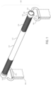
- the exercise bar 100 includes a handle tube 110 that is configured to accommodate hands of an end-user (e.g., end-user 610 of Figures 6 and 7 ).
- an end-user e.g., end-user 610 of Figures 6 and 7 .
- the handle tube 110 is about 30 centimeters (cm) in length. In some embodiments, the handle tube 110 is about 35 cm in length. In some embodiments, the handle tube 110 is about 40 cm in length. In some embodiments, the handle tube 110 is about 50 cm in length. In some embodiments, the handle tube 110 is about 53 cm in length. In some embodiments, the handle tube 110 is about 53.34 cm ( e.g ., about 21 inches) in length. In some embodiments, the handle tube 110 is about 54 cm in length. In some embodiments, the handle tube 110 is about 55 cm in length. In some embodiments, the handle tube 110 is about 60 cm in length. In some embodiments, the handle tube 110 is about 70 cm in length.
- the handle tube 110 is about 80 cm in length. In some embodiments, the handle tube 110 is about 90 cm in length. In some embodiments, the handle tube 110 is about 100 cm in length. In some embodiments, the handle tube 110 is about 110 cm in length. In some embodiments, the handle tube 110 is about 120 cm in length. In some embodiments, the handle tube 110 is about 130 cm in length. In some embodiments, the handle tube 110 is about 131 cm in length. In some embodiments, the handle tube 110 is about 140 cm in length. In some embodiments, the handle tube 110 is about 150 cm in length. In some embodiments, the exercise bar 100 is about 160 cm in length. In some embodiments, the handle tube 110 is about 170 cm in length.
- the handle tube 110 is about 180 cm in length. In some embodiments, the handle tube 110 is about 190 cm in length. In some embodiments, the handle tube 110 is about 200 cm in length. In some embodiments, the handle tube 110 is about 210 cm in length. In some embodiments, the handle tube 110 is about 220 cm in length ( e.g., approximately a length of an Olympic barbell). In some embodiments, the handle tube 110 is between 50 cm and 300 cm in length. In some embodiments, the handle tube 110 is between 100 cm and 250 cm in length. In some embodiments, the handle tube 110 is between 150 cm and 230 cm in length.
- a diameter of the handle tube 110 is 2.5 cm. In some embodiments, a diameter of the handle tube 110 is about 2.8 cm. In some embodiments, a diameter of the handle tube 110 is about 5 cm. In some embodiments, a diameter of the handle tube 110 is about 5.1 cm. In some embodiments, a diameter of the handle tube 110 is between 2.5 cm and 5.5 cm. In some embodiments, a diameter of the handle tube 110 is between 3.0 cm and 5.3 cm.
- the handle tube 110 includes one or more circumferential grip region types.
- the handle tube includes a first circumferential grip region type 112 and a second circumferential grip region type 114.
- the first circumferential grip region type 112 is a level (e.g., smooth) surface while the second circumferential grip region type 114 is characterized by a pattern of straight, angled, and/or crossed lines ( e.g., a result of being subjected to knurling).
- the handle tube 110 includes a first end portion and a second end portion (e.g., a right hand portion and a left hand portion).
- the second circumferential grip region type 114 is disposed at both the first end portion and the second end portion of the handle tube 110 while the first circumferential grip region is disposed on the handle tube 110 between the first and second end portions. Utilizing the circumferential grip regions at least improves the grip of an end-user while the user utilizes the exercise bar 100.
- the first and second end portions occupied by the second circumferential grip region type 114 are each between 10 cm and 30 cm in length.
- the first and second end portions occupied by the second circumferential grip region type 114 collectively occupy between 35 percent and 65 percent of the total length of the handle tube 110.
- the handle tube 110 includes a metal material such as a metal alloy (e.g., steel, iron, etc. ). In some embodiments, the handle tube 110 consists of metal or metal alloy ( e.g., steel, iron, etc .). In some embodiments the handle tube includes an austenite steel (e.g., AISI type no. 201, 202, 301, 302, 302B, 303, 303 (Se), 304, 304L, 305, 308, 309, 309S, 310, 310S, 314, 316, 317, 321, 347, or 348, etc .), a martensitic steel (e.g ., AISI type no.
- austenite steel e.g., AISI type no. 201, 202, 301, 302, 302B, 303, 303 (Se)
- the handle tube 110 includes a nickel alloy (e.g.
- handle tube 110 includes a high-strength low-alloy steel (HSLA).
- HSLA is a type of alloy steel that provides better mechanical properties or greater resistance to corrosion than carbon steel.
- the HSLA steel has a carbon content between 0.05-0.25%.
- the HSLA steel includes up to 2.0% manganese and small quantities of copper, nickel, niobium, nitrogen, vanadium, chromium, molybdenum, titanium, calcium, rare earth elements, or zirconium.
- HSLA steel that can be used to make the handle tube 100, see Degarmo et al., 2003, Materials and Processes in Manufacturing (9th ed.), Wiley, ISBN 0-471-65653-4 , and Oberg et al., 1996, Machinery's Handbook (25th ed.), Industrial Press Inc .
- Utilizing metal typically increases a load bearing capacity of the exercise bar 100.
- the present disclosure is not limited thereto.
- all or a portion of the handle tube 110 is coated with an elastomer (e.g., a rubberized coating).
- the handle tube 110 includes a grip disposed about a circumference thereof (e.g., a foam grip and/or a rubber grip, etc .).
- the handle tube 110 includes one or more circumferential grip region types.
- the handle tube includes a first circumferential grip region type 112 and a second circumferential grip region type 114.
- the first circumferential grip region type 112 is a level (e.g., smooth) uncoated surface while the second circumferential grip region type 114 is coated with an elastomer or a foam.
- the handle tube 110 includes a first end portion and a second end portion (e.g., a right hand portion and a left hand portion). Accordingly, in some such embodiments the second circumferential grip region type 114 is disposed at both the first end portion and the second end portion of the handle tube 110 while the first circumferential grip region is disposed on the handle tube 110 between the first and second end portions. Utilizing the circumferential grip regions at least improves the grip of an end-user while the user utilizes the exercise bar 100.
- the second circumferential grip region type 114 is coated with GR-S, neoprene, a nitrile rubber, a butyl rubber, a polysulfide rubber, or an ethylene-propylene rubber (e.g., ethylene propylene diene methylene (EPDM) rubber), a cyclized rubber (e.g. , Thermoprene).
- GR-S neoprene
- a nitrile rubber e.g., ethylene propylene diene methylene (EPDM) rubber
- EPDM ethylene propylene diene methylene
- a cyclized rubber e.g. , Thermoprene
- the handle tube 110 includes a longitudinal interior bore (e.g., longitudinal bore 202 of Figure 2 ). Further, in some embodiments the handle tube 110 includes a metal center shaft 150 that is fitted through the longitudinal interior bore 202. In some embodiments, the metal center shaft 150 is a solid rod ( e.g., a solid metal center shaft). In some embodiments, the metal center shaft 150 is a hollow rod. Moreover, in some embodiments the center shaft 150 includes a metal material ( e.g., steel, iron, etc. ) . In some embodiments, the center shaft 150 includes the same material as the handle tube 110. In some embodiments the center shaft 150 includes a material that is different than the handle tube 110.
- the center shaft 150 includes or consists of a metal or metal alloy (e.g ., steel, iron, etc .).
- the center shaft 150 includes an austenite steel (e.g ., AISI type no. 201, 202, 301, 302, 302B, 303, 303 (Se), 304, 304L, 305, 308, 309, 309S, 310, 310S, 314, 316, 317, 321, 347, or 348, etc .), a martensitic steel (e.g., AISI type no.
- the center shaft 150 includes a nickel alloy (e.g.
- the center shaft 150 includes a high-strength low-allow steel (HSLA).
- HSLA high-strength low-allow steel
- the length of the exposure of the first end portion and the second end portion of the center shaft 150 is about a length of a handle end cap ( e.g., end cap 130 of Figure 1 ).
- the center shaft 150 includes one or more tapers. For instance, in some embodiments the center shaft 150 is tapered from a first end portion to a middle portion of the center shaft. In some embodiments, the center shaft 150 is tapered from a second end portion to the middle portion of the center shaft. Tapering of the center shaft 150 allows for various components of the exercise bar 100 (e.g., a bearing 152, a washer 154, etc .) to be securely disposed on the center shaft.
- a respective band arm 140 is fitted onto a respective end portion of the center shaft 150.
- a first band arm 140 is fitted onto the first end of the center shaft 150 and, similarly, a second band arm 140 fitted onto the second end of the center shaft 150.
- Each respective band arm 140 is configured to accommodate a portion of an elastic band.
- the first band arm 140 is configured to accommodate a first portion of a first elastic band (e.g. , elastic band 190 of Figure 1 )
- the second band arm 140 is configured to accommodate a first portion of a second elastic band 190 (e.g., each respective band arm accommodates a respective elastic band.
- the present disclosure is not limited thereto.
- each respective band arm 140 accommodates a first portion of an elastic band 190 while the second band arm 140 accommodates a second portion of the elastic band. Additional details and information regarding configurations of one or more elastic bands will be described in more detail infra, with particular reference to at least Figures 6 and 7 .
- each respective band arm 140 is made of metal (e.g., steel, iron, etc. ).
- each respective band arm 140 is made of any of the materials disclosed above for the center shaft 150 and/or the handle tube 110.
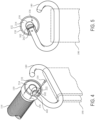
- each respective band arm 140 includes a hook region (e.g. , region 142 of Figure 1 ) that is configured to receive a respective end portion of an elastic band 190.
- Each hook region 142 provides a gap between the respective band arm 140 and the handle tube 110, allowing an elastic band 190 to be received through the gap by the band arm 140.
- the present disclosure is not limited thereto.
- each respective band arm 140 coupled to the handle tube 110 comprises two or more portions. Accordingly, in some embodiments, one or more of the two or more coupling portions is removably coupled to the handle tube 110, allowing for the elastic band 190 to be accommodated by the respective band arm 140.
- each band arm 140 includes a substantially level portion 144.
- the level portion 144 spans a length that is about a width of a corresponding elastic band 190.
- the level portion 144 allows for a respective elastic band 190 to rest in a state that provides an even distribution of resistance to the corresponding band arm 140 ( e.g., the respective band 190 lays flat against the corresponding band arm 140).
- the band 190 has a width of between 5 centimeters and 30 centimeters, and correspondingly, the level portion 144 is long enough to accommodate the full width of the band 190.
- the band 190 has a width of between 8 centimeters and 25 centimeters, and correspondingly, the level portion 144 is long enough to accommodate the full width of the band 190.
- the exercise bar 100 includes a corresponding handle end cap 130 for each respective end portion of the handle tube 110 (e.g., a first handle end cap 130 and a second handle end cap 130).
- Each respective end cap 130 includes a first end face (e.g., an interior face 212 of Figure 2 ) and a second end face ( e.g., an exterior face 214 of Figure 2 ).
- each respective handle end cap 130 includes a cylindrical exterior face ( e.g., exterior face 216 of Figure 2 ).
- each respective handle end cap 130 further includes a first bore hole 218 that is disposed along a central axis of the respective handle end cap between the first face 212 and second face 214 of the respective handle end cap. Accordingly, referring to Figure 3 , first and second respective end portions 302 of the center shaft 150 are fitted through the respective first bore hole of corresponding handle end caps 130 ( e.g., the first end portion 302a of the center shaft 150 is fitted through the first handle end cap 130 and the second end portion 302b of the center shaft is fitted through the second handle end cap 130).
- the exercise bar 100 includes a respective handle bearing (e.g. , bearing 152 of Figure 2 ) for each end portion 302 of the bar.
- Each handle bearing 152 includes a respective hollowed cylindrical piece that includes an inner circumferential surface and an outer circumferential surface (e.g., an inner diameter and an outer diameter).
- each handle bearing 152 is a bushing.
- each handle bearing 152 is made of a non-metallic material such as Nylon, polytetrafluoroethylene (PTFE), or another plastic material.
- PTFE polytetrafluoroethylene
- each handle bearing 152 is made of metal (e.g. , bronze).
- each handle bearing 152 is made of metal of sintered or otherwise porous constitution.
- each handle bearing 152 is lubricated with mineral oil, or similar lubricant such as water displacement lubricant.
- each handle bearing 152 is made of any of the materials disclosed above for the center shaft 150 or handle tube 110. While the handle bearing 152 can be made of any of the materials disclosed above for the center shaft 150 or handle tube 110, there is no requirement that the handle bearing 152 be made of the same material as the center shaft 150 or handle tube 110.
- each end portion 302 of the center shaft 150 is fitted through the respective cylindrical piece of the handle bearing 152, with the exterior circumferential surface of the respective cylindrical piece of the handle bearing 152 contacting, in turn, the inner circumferential surface of center shaft 150 as illustrated, for example, in Figure 3 .
- the handle bearing 152 includes a ball, needle, roller, or other bearing mechanism.
- the longitudinal interior bore of the handle tube 110 encapsulates and makes frictional contact with the outer surface of each handle bearing 152 as illustrated in Figure 3 . This frictional contact with the handle bearings 152 allows for the handle tube 110 to rotate independent from the handle end cap 130 and the center shaft 150, which improves at least a range of motion and/or a number of exercises capable of being performed by the bar 100.
- the exercise bar 100 includes a respective outer washer 154 that is fitted onto a corresponding end portion of the center shaft 150. Accordingly, a first face of each outer washer 154 is juxtaposed against an end face of the corresponding cylindrical piece 154, and a second face of the outer washer is juxtaposed against a first face of the corresponding handle end cap 130.
- each respective band arm 140 is fitted onto a respective end 302a of the center shaft 150 through attachment to the corresponding handle end cap 130.
- the details of such attachment in accordance with some embodiments, is shown in Figures 4 and 5 .
- the attachment of each respective band arm 140 to the corresponding handle end cap 130 includes a press fit attachment, a dowel and pin attachment (e.g., a first pin and a second pin), and other similar attachment mechanism capable of supporting a significant load (e.g ., such as 11,3 kg (25 pounds), 45,4 kg (100 pounds), 90,7 kg (200 pounds), 226,8 kg (500 pounds), 453,5 kg (1000 pounds), 680,3 kg (1500 pounds), etc. ) during operation.
- a significant load e.g ., such as 11,3 kg (25 pounds), 45,4 kg (100 pounds), 90,7 kg (200 pounds), 226,8 kg (500 pounds), 453,5 kg (1000 pounds), 680,3 kg (1500 pounds), etc.
- each respective handle end cap 130 includes a second bore hole (e.g., bore hole 442 of Figure 4 ) that is configured to accommodate a respective arm band 140.
- the second bore hole 442 is orthogonal to the first bore hole 218 ( e.g. , normal to a portion of the cylindrical exterior face 216 and extending to the central axis of the first cylindrical handle end cap 130 as illustrated in Figure 4 ). Accordingly, each respective arm band 140 is attached to the corresponding handle end cap by slotting a first end of the arm band 140 through the second bore hole 442 of the handle end cap.
- each respective end portion 302 of the center shaft 150 includes a notch ( e.g. , notch 502 of Figure 5 ) that receives the first end of a respective arm band 140.
- the first end portion 302a of the center shaft 150 includes a first notch 502 that receives the first end portion of the first arm band 140
- the second end portion 302b of the center shaft 150 includes a second notch 502 that receives the first end portion of the second arm band 140.
- the first notch 502 and the second notch 502 are disposed at a same side of the center shaft 150, which allows for each band arm 130 to be at a same level and/or orientation and provides an even distribution of resistance from the elastic bands 190 during operation of the exercise bar 100. Furthermore, the notch 502 allows for the respective band arm 140 to couple to the center shaft 150, allowing the center shaft to rotate within, and independent of, the handle tube 110.
- the exercise bar 100 includes a locking pin 134 for each respective end of the bar.
- each handle end cap 130 includes a third bore hole (e.g., bore hole 222 of Figure 4 and/or bore hole 136 of Figure 1 ).
- the third bore hole 222 is parallel to the first bore hole 218 between the first and second face of the respective handle end cap 130 while passing through, and orthogonal to, the second bore hole 442 of the handle end cap.
- the first end of each arm band 140 includes a corresponding bore hole 242 that is configured to receive the locking pin 134 when the locking pin 134 is slotted through the third bore hole 136/222.
- each locking pin 134 locks the first end of the respective arm band 140 to the corresponding handle end cap 130 by insertion of the locking pin 134 through both the third bore hole 222 of the handle end cap 130 and the bore hole 242 of the first arm band.
- the locking pin 134 does not interfere with a respective washer 154 ( e.g., the washer 154 is free to rotate).
- each respective handle end cap 130 includes a removably coupled cover 132.
- the cover 132 is coupled to the corresponding handle end cap 130 through the locking pin 134.
- the cover 132 is coupled to the corresponding handle end cap 130 through a press-fit (e.g. , snap) connection.
- the cover 132 includes each bore hole associated with the above described second end face 214.
- the cover 132 includes respective bore holes 136, 222, 442, etc.
- the cover 132 secures the pin 134 through a hole in the cover ( e.g., hole 222) while also, optionally, providing an aesthetic area to configure for a designer of the present disclosure.
- the cover 132 includes a graphic or an artwork such as a corporate logo.
- the cover 132 includes a soft material such as rubber, which prevents the exercise bar 100 from inadvertently damaging a surrounding environment and/or an end-user.
- the cover 132 does not include a bore hole associated with the above described second end face 214 ( e.g., bore hole 134 and 136).
- the third bore hole 222 penetrates the corresponding handle end cap 130 and the cover 132.
- the third bore hole 222 penetrates the corresponding handle end cap 130 but not the cover 132.
- the cover 132 is removably coupled to the second end face 214 and includes an uninterrupted face ( e.g. , there is no hole through the cover 132).
- the cover 132 is accommodated by the respective handle end cap 130 ( e.g., the cover fits into an end portion of the handle end cap).
- the respective handle end cap 130 is accommodated by the cover 132 (e.g., the handle end cap fits into an end portion of the cover).
- the present disclosure provides an exercise kit 600 for performing exercises.
- an end-user performs a curl from a first position (e.g., a first position depicted in Figure 6 ) to a second position ( e.g ., a second position depicted in Figure 7 ).
- the exercise kit includes an exercise bar 100, a base 650, and one or more elastic bands 190 that couple the exercise bar to the base.
- the base is made of CNC milled Marine Grade HDPE (high density polyethylene).
- each elastic band 190 in the one or more elastic bands has a unique elasticity, or similarly maximum resistance.
- the exercise kit 600 includes two elastic bands 190.
- the two elastic bands 190 include a first elastic band of a first maximum resistance (e.g. , a low maximum resistance such as 2,3 kg (5 pounds)) and a second band of a second maximum resistance different than the first maximum resistance (e.g. , a high resistance such as 45,4 kg (100 pounds)).
- the exercise kit 600 includes at least three exercise bands 190.
- the at least three exercise bands 190 of the exercise kit 600 include a first elastic band 190-1 characterized by a first maximum resistance, a second elastic band 190-2 characterized by a second maximum resistance that is greater than the first maximum resistance, and a third elastic band 190-3 having a third maximum resistance that is greater than the second maximum resistance.
- a respective maximum resistance of each band 190 is determined, at least in part, by a width and/or thickness of the band (e.g. , a lower resistance band includes a thinner width and/or thickness compared to a higher resistance band).
- the third band 190-3 has a width is about a same length as the level portion 144 of each band arm 140 ( e.g., the width of the third band is of from about 75% to about 100% the length of the level portion of the band arm).
- the second band 190-2 has a width is less than the length as the level portion 144 of each band arm 140 ( e.g., the width of the second band is of from about 40% to about 75% the length of the level portion of the band arm).
- the first band 190-1 has a width that is less than the length as the level portion 144 of each band arm 140 (e.g., the width of the first band is of from about 5% to about 40% the length of the level portion of the band arm).
- the one or more elastic bands 190 of the present disclosure includes a band that is a continuous flat loop ( e.g., a rehabilitation band and/or a fit loop band).
- the one or more elastic bands 190 of the present disclosure includes a band that has a handle (e.g., an ankle cuff, a hard handle such as plastic, a soft handle such as foam, etc .). Accordingly, in some embodiments a user utilizes their body ( e.g ., feet, back, etc .) to perform an exercise without the base 650.
- the elastic band 190 provides about 11,3 kg (25 lbs) of maximum resistance to an end user of the exercise bar 100. In some embodiments, the elastic band 190 provides about 22,7 kg (50 lbs) of maximum resistance to an end user of the exercise bar 100. In some embodiments, the elastic band 190 provides about 45,5 kg (100 lbs) of maximum resistance to an end user of the exercise bar 100. In some embodiments, the elastic band 190 provides about 68,0 kg (150 lbs) of maximum resistance to an end user of the exercise bar 100. In some embodiments, the elastic band 190 provides about 90,7 kg (200 lbs) of maximum resistance to an end user of the exercise bar 100.
- the elastic band 190 provides about 113,4 kg (250 lbs) of maximum resistance to an end user of the exercise bar 100. In some embodiments, the elastic band 190 provides about 136,1 kg (300 lbs) of maximum resistance to an end user of the exercise bar 100. In some embodiments, the elastic band 190 provides about 158,7 kg (350 lbs) of maximum resistance to an end user of the exercise bar 100. In some embodiments, the elastic band 190 provides about 181,4 kg (400 lbs) of maximum resistance to an end user of the exercise bar 100. In some embodiments, the elastic band 190 provides about 226,8 kg (500 lbs) of maximum resistance to an end user of the exercise bar 100. In some embodiments, the elastic band 190 provides about 272,1 kg (600 lbs) of maximum resistance to an end user of the exercise bar 100.
- the elastic band 190 provides between 9,1 kg and 27,2 kg (20 lbs and 60 lbs) of maximum resistance to an end user of the exercise bar 100. In some embodiments, the elastic band 190 provides between 11,3 kg and 40,8 kg (25 lbs and 90 lbs) of maximum resistance to an end user of the exercise bar 100. In some embodiments, the elastic band 190 provides between 34,0 kg and56,7 kg (75 lbs and 125 lbs) of maximum resistance to an end user of the exercise bar 100. In some embodiments, the elastic band 190 provides between 49,9 kg and 81,6 kg (110 lbs and 180 lbs) of maximum resistance to an end user of the exercise bar 100.
- the elastic band 190 provides between 79,4 kg and 108,8 kg (175 lbs and 240 lbs) of maximum resistance to an end user of the exercise bar 100. In some embodiments, the elastic band 190 provides between 104,3 kg and 127,0 kg (230 lbs and 280 lbs) of maximum resistance to an end user of the exercise bar 100. In some embodiments, the elastic band 190 provides between (124,7 kg and 147,4 kg (275 lbs and 325 lbs) of maximum resistance to an end user of the exercise bar 100. In some embodiments, the elastic band 190 provides between 147,4 kg and 170,1 kg (325 lbs and 375 lbs) of maximum resistance to an end user of the exercise bar 100.
- the elastic band 190 provides between 158,7 kg and 192,7 kg (350 lbs and 425 lbs) of maximum resistance to an end user of the exercise bar 100. In some embodiments, the elastic band 190 provides between 181,4 kg and 215,4 kg (400 lbs and 475 lbs) of maximum resistance to an end user of the exercise bar 100. In some embodiments, the elastic band 190 provides between 204,1 kg and 294,8 kg (450 lbs and 650 lbs) of maximum resistance to an end user of the exercise bar 100. In some embodiments, the elastic band 190 provides between 294,8 kg and 340,1 kg (650 lbs and 750 lbs) of maximum resistance to an end user of the exercise bar 100.
- the elastic band 190 provides between 10 kilograms and 30 kilograms of maximum resistance to an end user of the exercise bar 100. In some embodiments, the elastic band 190 provides between 13 kilograms and 45 kilograms of maximum resistance to an end user of the exercise bar 100. In some embodiments, the elastic band 190 provides between 35 kilograms and 63 kilograms of maximum resistance to an end user of the exercise bar 100. In some embodiments, the elastic band 190 provides between 55 kilograms and 90 kilograms of maximum resistance to an end user of the exercise bar 100. In some embodiments, the elastic band 190 provides between 80 kilograms and 120 kilograms of maximum resistance to an end user of the exercise bar 100. In some embodiments, the elastic band 190 provides between 130 kilograms and 140 kilograms of maximum resistance to an end user of the exercise bar 100.
- the elastic band 190 provides between 125 kilograms and 180 kilograms of maximum resistance to an end user of the exercise bar 100. In some embodiments, the elastic band 190 provides between 160 kilograms and 180 kilograms of maximum resistance to an end user of the exercise bar 100. In some embodiments, the elastic band 190 provides between 160 kilograms and 210 kilograms of maximum resistance to an end user of the exercise bar 100. In some embodiments, the elastic band 190 provides between 200 kilograms and 240 kilograms of maximum resistance to an end user of the exercise bar 100. In some embodiments, the elastic band 190 provides between 225 kilograms and 325 kilograms of maximum resistance to an end user of the exercise bar 100. In some embodiments, the elastic band 190 provides between 325 kilograms and 325 kilograms of maximum resistance to an end user of the exercise bar 100.
- each respective elastic band in the one or more elastic bands has a thickness of at least 1 cm and a length of between 180 centimeters and 220 centimeters when the respective elastic band is in an unextended state. In some embodiments each respective elastic band in the one or more elastic bands has a thickness of at least 1 cm, at least 1.5 cm, at least 2 cm, at least 2.5 cm, or at least 3.0 cm and a length of between 100 centimeters and 220 centimeters or between 100 centimeters and 280 centimeters when the respective elastic band is in an unextended state.
- the present disclosure provides a first band 190-1 that includes a thickness of about 5 mm, a width of about 2.1 cm (0.8125 inches), a length of about 104,1 cm (41 inches), and about a 45,4 kg (100 lbs) force production capacity.
- the present disclosure provides a second band 190-2 that includes a thickness of about 5 mm, a width of about 2.9 cm (1.125 inches), a length of about 104,1 cm (41 inches), and about a 72,6 kg (160 lbs) force production capacity.
- the present disclosure provides a third band 190-1 that includes a thickness of about 5 mm, a width of about 4,4 cm (1.75 inches), a length of about 104,1 cm (41 inches), and about a 108,8 kg (240 lbs) force production capacity.
- the present disclosure provides a fourth band 190-1 that includes a thickness of about 5 mm, a width of about 6.4 cm (2.5 inches), a length of about 104,1 cm (41 inches), and about a 136,1 kg (300 lbs) force production capacity.
- the disclosed exercise kit is a variable resistance device meaning that the further the elastic band 190 is extended by a user, the more resistance the device will exert. So, for instance, when the user extends a band a first distance beyond the relaxed state of the band 190, the band exerts a first resistance (e.g. , 36,3 kg (80 pounds)). When the user extends the band beyond the first distance to a second distance beyond the first state, the band exerts a second resistance that is greater than the first resistance (e.g. , 90,7 kg (200 pounds)). When the user extends the band beyond the second distance to a third distance beyond the first second distance, the band exerts a third resistance that is greater than the second resistance (e.g.
- the resistance (tension on the muscle) changes (varies) as the user performs an exercise.
- the resistance is less when the user starts to perform a repetition and it is most when the user is at the end of the repetition.
- the disclosed variable resistance exercised kit is different than free weights. Free weights, such as barbells and dumbbells, provide a constant resistance.
- the user performs an exercise in which the user initially exerts the exercise bar 100 across a full range of motion, for instance between (i) to the region in which the elastic band 190 exerts a high resistance (e.g. , the third resistance described above) and (ii) the relaxed state in which the elastic band 190 exerts no or minimal resistance, a series of times until the user can no longer exert the exercise bar 100 across the full range of motion of the elastic band.
- the user exerts the exercise bar 100 across an intermediate range of motion, for instance between (i) the region in which the elastic band 190 exerts less than the highest resistance (e.g.
- the user exerts the exercise bar 100 across minimal range of motion, for instance between (i) the region in which the elastic band 190 exerts less than the intermediate resistance (e.g. the first resistance described above) and (ii) the relaxed state in which the elastic band 190 exerts no or minimal resistance, a series of times until the user can no longer exert the exercise bar 100 through the minimal range of motion.
- the intermediate resistance e.g. the first resistance described above
- the relaxed state in which the elastic band 190 exerts no or minimal resistance a series of times until the user can no longer exert the exercise bar 100 through the minimal range of motion.
- the user can no longer exert the exercise bar through any of the above ranges of motion until a later time, that is, the user has achieved absolute fatigue. In this way, through such diminishing ranges of motion, osteogenic stimulus is achieved. As such, a program in which such an exercise is done on a regular basis leads to increased muscle strength.
Landscapes
- Health & Medical Sciences (AREA)
- Orthopedic Medicine & Surgery (AREA)
- General Health & Medical Sciences (AREA)
- Physical Education & Sports Medicine (AREA)
- Life Sciences & Earth Sciences (AREA)
- Biophysics (AREA)
- Rehabilitation Tools (AREA)
- Massaging Devices (AREA)
Priority Applications (1)
| Application Number | Priority Date | Filing Date | Title |
|---|---|---|---|
| EP25163415.0A EP4591953A3 (en) | 2019-02-22 | 2020-02-18 | Variable resistance exercise devices |
Applications Claiming Priority (2)
| Application Number | Priority Date | Filing Date | Title |
|---|---|---|---|
| US16/283,419 US11701539B2 (en) | 2019-02-22 | 2019-02-22 | Variable resistance exercise devices |
| PCT/US2020/018577 WO2020172127A1 (en) | 2019-02-22 | 2020-02-18 | Variable resistance exercise devices |
Related Child Applications (1)
| Application Number | Title | Priority Date | Filing Date |
|---|---|---|---|
| EP25163415.0A Division EP4591953A3 (en) | 2019-02-22 | 2020-02-18 | Variable resistance exercise devices |
Publications (3)
| Publication Number | Publication Date |
|---|---|
| EP3927439A1 EP3927439A1 (en) | 2021-12-29 |
| EP3927439A4 EP3927439A4 (en) | 2022-11-16 |
| EP3927439B1 true EP3927439B1 (en) | 2025-03-19 |
Family
ID=72142232
Family Applications (2)
| Application Number | Title | Priority Date | Filing Date |
|---|---|---|---|
| EP20759154.6A Active EP3927439B1 (en) | 2019-02-22 | 2020-02-18 | Variable resistance exercise devices |
| EP25163415.0A Pending EP4591953A3 (en) | 2019-02-22 | 2020-02-18 | Variable resistance exercise devices |
Family Applications After (1)
| Application Number | Title | Priority Date | Filing Date |
|---|---|---|---|
| EP25163415.0A Pending EP4591953A3 (en) | 2019-02-22 | 2020-02-18 | Variable resistance exercise devices |
Country Status (5)
| Country | Link |
|---|---|
| US (3) | US11701539B2 (da) |
| EP (2) | EP3927439B1 (da) |
| CN (2) | CN116764162B (da) |
| DK (1) | DK3927439T3 (da) |
| WO (1) | WO2020172127A1 (da) |
Families Citing this family (16)
| Publication number | Priority date | Publication date | Assignee | Title |
|---|---|---|---|---|
| USD887067S1 (en) | 2017-03-13 | 2020-06-09 | Buster And Punch Limited | Light fixture |
| USD914113S1 (en) | 2019-02-22 | 2021-03-23 | Jaquish Biomedical Corporation | Exercise apparatus |
| US11701539B2 (en) * | 2019-02-22 | 2023-07-18 | Jaquish Biomedical Corporation | Variable resistance exercise devices |
| US11033774B1 (en) * | 2020-01-24 | 2021-06-15 | Gerald M. Clarke | Exercise band bar |
| USD934355S1 (en) * | 2020-02-05 | 2021-10-26 | Interactive Strenght, Inc. | Long bar handle |
| USD934356S1 (en) * | 2020-02-05 | 2021-10-26 | Interactive Strength, Inc. | Short bar handle |
| USD979104S1 (en) | 2020-02-28 | 2023-02-21 | Buster And Punch Limited | Light fitting |
| US11701535B2 (en) | 2020-10-28 | 2023-07-18 | Arturo E. Holmes | Stretching apparatus |
| USD954858S1 (en) | 2020-11-30 | 2022-06-14 | Golden Gate Solutions, Inc. | Exercise bar with platform |
| US20220257992A1 (en) * | 2021-02-16 | 2022-08-18 | Floyd E. Reed, III | Universal exercise band retaining device |
| CN118234546A (zh) * | 2021-10-06 | 2024-06-21 | 贾奎什生物医学公司 | 提供感觉反馈的健身杆 |
| USD970654S1 (en) * | 2021-12-06 | 2022-11-22 | Xiaohuan Gu | Exercise device |
| USD1040945S1 (en) * | 2022-05-06 | 2024-09-03 | Hebei Zhangkong Barbell Manufacturing Co., Ltd. | Sliding barbell |
| USD988442S1 (en) * | 2022-09-20 | 2023-06-06 | Jaquish Biomedical Corporation | Exercise apparatus |
| US11833385B1 (en) * | 2023-03-24 | 2023-12-05 | Exemplar Design, Llc | Exercise bar for use with flexible resistance bands |
| DE202024105958U1 (de) | 2024-10-16 | 2024-10-25 | Ronald Brandl | Trainingsgerät mit verschiebbar gelagerten Griffen und Einhängemitteln |
Family Cites Families (141)
| Publication number | Priority date | Publication date | Assignee | Title |
|---|---|---|---|---|
| US825955A (en) * | 1905-09-02 | 1906-07-17 | Harry William Bohache | Attachment for indian clubs. |
| US1019861A (en) * | 1910-06-24 | 1912-03-12 | Henry W Titus | Exercising apparatus. |
| US1997139A (en) * | 1934-01-30 | 1935-04-09 | Gardener | Exercising device |
| US2470815A (en) * | 1948-03-10 | 1949-05-24 | Roosevelt W W Harvey | Athletic apparatus |
| US2637555A (en) * | 1950-07-07 | 1953-05-05 | Helmuth R Klaudt | Exercise bar |
| US3117781A (en) | 1961-12-21 | 1964-01-14 | Louis M Vargo | Isometric contraction exercise apparatus having a rotatable upper member for adjusting the length of the conecting cords |
| US3193288A (en) | 1962-09-11 | 1965-07-06 | Spain Le Vell De | Physical conditioning device having elastic strands |
| US3215429A (en) * | 1962-09-18 | 1965-11-02 | Joseph S Shaboo | Spring biased exercising apparatus |
| US3256015A (en) * | 1963-01-09 | 1966-06-14 | William E Perrin | Exercising apparatus |
| US3785644A (en) | 1971-11-02 | 1974-01-15 | R Bradley | Pull type exercising device having with frictional resistance to pulling |
| US3910573A (en) | 1974-09-03 | 1975-10-07 | Michael Jamba | Four piece isometric exerciser |
| US4200281A (en) | 1977-10-13 | 1980-04-29 | Clifford Wang | Elastic pull type exercising device |
| US4257592A (en) | 1978-11-29 | 1981-03-24 | Arthur Jones | Exercising apparatus with improvements in handle structure, rope arrangement, and clamping means |
| US4441707A (en) | 1981-07-15 | 1984-04-10 | Bosch Jack L | Isometric exerciser belt for joggers and the like |
| USD274829S (en) * | 1982-01-11 | 1984-07-24 | Bankier Jack O | Exercise bar or similar article |
| US4518162A (en) * | 1982-09-30 | 1985-05-21 | Oates William J | Weighted exercise bar |
| US4770414A (en) * | 1985-12-20 | 1988-09-13 | Eric Fredrickson | Body exercising device |
| US4893810A (en) * | 1986-07-21 | 1990-01-16 | Lee Scott H | Quick release collar |
| US5112287A (en) * | 1990-11-27 | 1992-05-12 | Brewer Aaron F | Exercising device |
| US5125649A (en) * | 1990-12-06 | 1992-06-30 | Conrad Fuller | Exercise apparatus utilizing a booster bar and shock cords |
| US5197934A (en) | 1991-01-17 | 1993-03-30 | Wirtz Donald E | Elastic exercise device |
| US5645511A (en) | 1991-11-21 | 1997-07-08 | Green Journal Ltd. | Exercise apparatus |
| US5178596A (en) | 1991-12-13 | 1993-01-12 | Mcintire Nora L | Exercise apparatus |
| USD353419S (en) | 1993-07-26 | 1994-12-13 | Sprague Edwin J | Aerobic exercise platform |
| US5540642A (en) | 1993-08-12 | 1996-07-30 | Sprague; Edwin J. | Aerobic exercise device |
| US5514058A (en) | 1995-01-13 | 1996-05-07 | Nick Buoni | Portable whole body exercise device |
| US5653665A (en) | 1995-08-24 | 1997-08-05 | Neeley; Michael Joseph | Apparatus to provide relief for back pain |
| US5746687A (en) | 1995-09-27 | 1998-05-05 | Vial; Silvano | Multi-purpose exercise device |
| US5885196A (en) | 1996-11-25 | 1999-03-23 | Kordun, Ltd. | Multiple elastic cable exercise device |
| US5776041A (en) | 1997-01-08 | 1998-07-07 | Fisher; Karol | Exercise device with an elastic member |
| US5904640A (en) * | 1997-02-14 | 1999-05-18 | Shahinian; Araz R. | Extended centripetal rotator exercise device |
| US5830110A (en) | 1997-07-28 | 1998-11-03 | Fielding; Rory F. | Spring-actuated, portable weight training device |
| US6203476B1 (en) | 1999-11-19 | 2001-03-20 | Allen Yin | Physical exercising apparatus |
| DE29922904U1 (de) | 1999-12-28 | 2000-02-17 | Hsieh, Jung-Pao, Chungli, Taoyuan | Mehrzweckgleitgerät |
| US20060019806A1 (en) * | 2000-01-05 | 2006-01-26 | Mikulski Walter J | Portable excercise assembly |
| US7601101B2 (en) | 2000-01-27 | 2009-10-13 | Powerbox Fitness, Llc | Exercise apparatus |
| US20020123416A1 (en) * | 2001-03-02 | 2002-09-05 | Huang Chin Chiu | Body building roller |
| US6544152B2 (en) | 2001-03-23 | 2003-04-08 | Frank Rosati | Exercise device |
| US6648804B2 (en) * | 2001-06-22 | 2003-11-18 | Ming Chin Chen | Exerciser combination for various kinds of exercises |
| US6837837B2 (en) * | 2001-11-19 | 2005-01-04 | Robert Lee Nethery | Exercise device |
| USD482748S1 (en) | 2002-04-05 | 2003-11-25 | Powerbase Fitness, Llc | Exercise platform |
| USD474818S1 (en) | 2002-04-29 | 2003-05-20 | Jao-Hsing Tsai | Pulling exerciser |
| US7090627B1 (en) * | 2002-09-26 | 2006-08-15 | Andre Laddarrel Walker | Device for exercising abdominal muscles |
| US7175574B2 (en) | 2003-02-07 | 2007-02-13 | Spri Products, Inc. | Exercise device |
| JP2005035682A (ja) | 2003-07-15 | 2005-02-10 | Komori Corp | チョッパテーブル |
| US20060276314A1 (en) * | 2003-10-22 | 2006-12-07 | Wilson Jeffrey D | Bar with sliding handgrips for resistance exercise devices |
| US20050113218A1 (en) * | 2003-11-21 | 2005-05-26 | Sewitch Stanley A.Jr. | Multipurpose martial arts training device |
| US20050113222A1 (en) * | 2003-11-24 | 2005-05-26 | Dovner Edward R. | Resistive elastic tube assembly for exercise device |
| US20050113221A1 (en) * | 2003-11-24 | 2005-05-26 | Dovner Edward R. | Tube connector for exercise device with elastic resistance |
| US20050113223A1 (en) * | 2003-11-24 | 2005-05-26 | Dovner Edward R. | Exercise device with elastic resistance |
| US7052449B2 (en) | 2004-03-18 | 2006-05-30 | Ping Chen | Gym board |
| US20050233877A1 (en) * | 2004-04-19 | 2005-10-20 | Chang-I Lin | Multifunction gymnastic apparatus |
| US20050239617A1 (en) * | 2004-04-22 | 2005-10-27 | Rosanna Tenaglia | Exercise equipment system |
| US20050245370A1 (en) * | 2004-04-28 | 2005-11-03 | Boland Kevin O | Powerwalk plus |
| US8025615B1 (en) * | 2004-05-15 | 2011-09-27 | Jim Wallace Sargent | Exercise roll bar device |
| US7175552B2 (en) * | 2004-07-20 | 2007-02-13 | Wilson Sporting Goods Co. | Ball bat formed of carburized steel |
| US7578775B2 (en) | 2004-09-03 | 2009-08-25 | Terry Douglas C | Personal exercise system |
| US7175573B1 (en) * | 2005-05-02 | 2007-02-13 | Chin-Chen Huang | Exercising device having multiple functions |
| USD526367S1 (en) * | 2005-05-25 | 2006-08-08 | Loccarini Darin A | Portable trainer |
| US20070197352A1 (en) * | 2006-02-23 | 2007-08-23 | Andrew-Bud Charniga | Barbell set and plates |
| US7740570B2 (en) | 2006-03-06 | 2010-06-22 | Edith Winston | Aquatic exercise device |
| US7922624B1 (en) | 2006-04-12 | 2011-04-12 | Fairhurst Productions, Inc. | Multi-function exercise platform |
| US7465259B2 (en) * | 2006-09-20 | 2008-12-16 | Harry Mok | Exercise apparatus |
| JP4834591B2 (ja) * | 2007-03-29 | 2011-12-14 | 日本発條株式会社 | ゴルフシャフト、ゴルフクラブ、および、ゴルフシャフトの製造方法 |
| US20080287272A1 (en) * | 2007-05-17 | 2008-11-20 | Gerald Luckadue | Exercise apparatus |
| US7387599B1 (en) * | 2007-07-03 | 2008-06-17 | Yan Hsu | Massaging body-gym apparatus |
| US7892158B2 (en) * | 2007-12-26 | 2011-02-22 | Varga Thomas A | Pushup apparatus |
| DE202008000763U1 (de) | 2008-01-18 | 2008-03-20 | Klein, Frank | Gymnastikgerät |
| US7833141B2 (en) * | 2008-01-28 | 2010-11-16 | J & M Medical Sales, Llc | Exercise apparatus and methods |
| USD604374S1 (en) | 2008-05-25 | 2009-11-17 | Edison Nation, Llc | Exercise assembly |
| USD590457S1 (en) | 2008-06-06 | 2009-04-14 | E. Mishan & Sons, Inc. | Exerciser platform |
| US20100152002A1 (en) * | 2008-12-11 | 2010-06-17 | Knight Mary Beth | Fitness training apparatus with weight and resistance features |
| US8142337B2 (en) * | 2009-01-04 | 2012-03-27 | Hall William B | Exercise pole device |
| US8142335B1 (en) * | 2009-03-30 | 2012-03-27 | Emberstone Technologies, LLC | Spring collars having permanent magnets for non-use storage |
| US8088050B2 (en) * | 2009-04-06 | 2012-01-03 | Aucamp Frederick P | Portable exercise equipment |
| US8702574B2 (en) * | 2009-05-01 | 2014-04-22 | Dama Claudy ABRANCHESS | Method and system for performing linear and circular movement patterns |
| US20100319814A1 (en) | 2009-06-17 | 2010-12-23 | Teresa Estela Perez | Bainitic steels with boron |
| USD633155S1 (en) | 2009-11-02 | 2011-02-22 | Larry Brun | Exercise tube |
| US8172734B2 (en) * | 2009-12-23 | 2012-05-08 | Ace Specialty, Inc. | Dumbbell with antimicrobial handle |
| US8721507B2 (en) * | 2010-04-13 | 2014-05-13 | Vaughan Martin Blancher | Multi-planar resistance band exercise system |
| US8033964B1 (en) * | 2010-06-08 | 2011-10-11 | Chin-Long Chen | Dumbbell assembly |
| USD682374S1 (en) | 2010-09-11 | 2013-05-14 | William T. Wilkinson | Exercise resistance device |
| AU2011312085A1 (en) * | 2010-10-05 | 2013-05-02 | Kiril Stefan Alexandrov | Portable doorway recreation apparatus |
| US20120094812A1 (en) * | 2010-10-19 | 2012-04-19 | Pec 1000, Llc | Exercise bar having sliding hand grips |
| US9254405B1 (en) * | 2010-11-29 | 2016-02-09 | Sammy Black Marji | Variable resistant exercise band, device containing same and exercise method |
| TWM410578U (en) * | 2011-03-04 | 2011-09-01 | Sports Ace Internat Co Ltd | rotating dumbbell |
| USD655356S1 (en) | 2011-05-11 | 2012-03-06 | Stefan Sandman | Training tool |
| US20130310233A1 (en) * | 2012-05-19 | 2013-11-21 | Kevin James Dahlquist | Tubular exercise device with selective foot and ankle mounting |
| US8936539B2 (en) * | 2012-09-26 | 2015-01-20 | Fit In Fitness, LLC | Balance board exercise apparatus |
| US9259606B2 (en) * | 2012-12-05 | 2016-02-16 | Edward Anthony Wolan | Portable resistance band exercise machine |
| US20140228183A1 (en) * | 2013-02-08 | 2014-08-14 | Dana Falconi | Elastic Flat Band |
| US9630048B2 (en) * | 2013-03-15 | 2017-04-25 | Arqex Outdoor Fitness Systems, Llc | Variable resistance band assembly and method of using the same |
| US9724553B2 (en) * | 2013-03-15 | 2017-08-08 | Arqex Outdoor Fitness Systems, Llc | Resistance band assembly and a method of varying a resistive force applied thereby |
| US9555278B2 (en) * | 2013-03-15 | 2017-01-31 | Arqfx Outdoor Fitness Systems, Llc | Strength training and stretching system and resistance band assembly for use therewith |
| US20140287889A1 (en) * | 2013-03-19 | 2014-09-25 | Grace Premier Fitness And Wellness Products, Inc. | Barbell |
| CA2816146A1 (en) | 2013-05-07 | 2014-11-07 | Giacomo Villella (Jack) | Exercise bar |
| US10843026B2 (en) * | 2013-05-23 | 2020-11-24 | B and A Health and Fitness, LLC | Exercise system and kit |
| US9352184B2 (en) * | 2013-05-23 | 2016-05-31 | B&A Health And Fitness, Llc | Exercise system and kit |
| US9533191B2 (en) * | 2013-07-03 | 2017-01-03 | Alison M. Carbone | Agility and strength improvement apparatus |
| USD724163S1 (en) | 2013-11-07 | 2015-03-10 | Jon Kelley | Exercise apparatus |
| US9808666B1 (en) * | 2014-04-21 | 2017-11-07 | Colin M. BURKINSHAW | Full body exercise apparatus |
| US9180335B1 (en) * | 2014-06-04 | 2015-11-10 | Yung-Cheng Wu | Exercise wheel |
| US9919176B2 (en) * | 2014-08-06 | 2018-03-20 | Rebar Llc | Exercise resistance device |
| USD748745S1 (en) * | 2014-08-29 | 2016-02-02 | Bhas Innovation As | Multibalance trainer |
| US9907993B2 (en) * | 2014-09-02 | 2018-03-06 | Gregory Alan Penney | Elastomeric hand grips |
| USD739481S1 (en) | 2014-09-18 | 2015-09-22 | Adam Sloan Glickfield | Press bench |
| US10940354B2 (en) * | 2014-09-26 | 2021-03-09 | Dennis Ross Oltorik Jr. | Portable resistance workout apparatuses and systems |
| US10220236B2 (en) * | 2014-09-26 | 2019-03-05 | Rhino Boss Llc | Portable resistance workout apparatuses and systems |
| US10486013B2 (en) * | 2014-11-24 | 2019-11-26 | John Wallander | Exercise bar |
| USD910124S1 (en) * | 2015-07-17 | 2021-02-09 | Jaquish Biomedical Corporation | Exercising apparatus |
| USD778374S1 (en) * | 2015-01-23 | 2017-02-07 | Jaquish Industrial Research LLC | Exercise platform with bar configured for use with resistance bands |
| US20160287929A1 (en) * | 2015-04-02 | 2016-10-06 | Bachar Corporation | Treadmill extender |
| US10022578B2 (en) * | 2015-07-23 | 2018-07-17 | Modern Hygiene, LLC | Muscle therapy device |
| US9925410B2 (en) * | 2015-09-24 | 2018-03-27 | James S Duffy | Exercise wedge |
| US9844696B2 (en) | 2015-10-13 | 2017-12-19 | Engine Fitness | Portable exercise device |
| WO2017075183A1 (en) * | 2015-10-28 | 2017-05-04 | Daniel Smith | Therapeutic stick and method of use |
| USD798396S1 (en) | 2015-11-02 | 2017-09-26 | Andre AGATE | Exercise bar |
| EP3397101A4 (en) * | 2016-01-04 | 2019-08-28 | Bell Sports, Inc. | HELMET WITH BORDER TOP AND ELASTOMER BRACKETS |
| US20170209730A1 (en) * | 2016-01-21 | 2017-07-27 | Brian Sise | Physical Exercise Assembly |
| US20170216650A1 (en) * | 2016-01-28 | 2017-08-03 | Louie Simmons | Plate loaded abduction-adduction press bar |
| US10245461B2 (en) * | 2016-03-16 | 2019-04-02 | Dave Peter Bruni | Strength training system and method of using same |
| US20170274239A1 (en) * | 2016-03-24 | 2017-09-28 | Edward M. Barella | Knotted Flat Elastic Stretch Band Exercise Bar |
| USD802153S1 (en) | 2016-06-28 | 2017-11-07 | Modern Hygiene, LLC | Muscle therapy device |
| TWI610702B (zh) * | 2016-08-03 | 2018-01-11 | 岱宇國際股份有限公司 | 多功能健力器 |
| US10245466B2 (en) * | 2016-10-19 | 2019-04-02 | Viktor Uygan | Foot stretching and strengthening apparatus |
| US11000447B2 (en) * | 2016-11-07 | 2021-05-11 | Koka Co., LLC | Portable modular fitness system |
| US10561889B2 (en) * | 2016-12-13 | 2020-02-18 | Dale Rossi | Physical therapy system |
| USD849857S1 (en) | 2016-12-15 | 2019-05-28 | Michael G. Tartell | Exercise platform |
| USD842940S1 (en) | 2017-01-24 | 2019-03-12 | Disruptive Force Llc | Exercise stick |
| CN206566424U (zh) * | 2017-02-23 | 2017-10-20 | 上海荻戴实业发展有限公司 | 一种多功能肌群训练器 |
| US20180236299A1 (en) * | 2017-02-23 | 2018-08-23 | Wesley Warriner | Sleeve Grip Applications |
| CN206934584U (zh) * | 2017-06-14 | 2018-01-30 | 南昌师范高等专科学校 | 一种腹部健身器材 |
| US11547890B2 (en) * | 2018-04-25 | 2023-01-10 | Christopher S. Stewart | Resistance-based exercise device |
| USD854635S1 (en) | 2018-05-10 | 2019-07-23 | Coulter Ventures, LLC | Pull up bar |
| CN110833673A (zh) * | 2018-08-16 | 2020-02-25 | 宁波睿特菲体育科技有限公司 | 穿戴式辅助件及其健身套装和应用 |
| US11701539B2 (en) * | 2019-02-22 | 2023-07-18 | Jaquish Biomedical Corporation | Variable resistance exercise devices |
| USD865084S1 (en) | 2019-03-28 | 2019-10-29 | Stephen N. Croxton | Exercise device |
| USD937369S1 (en) * | 2019-11-07 | 2021-11-30 | Jaquish Biomedical Corporation | Exercise apparatus |
| US11383120B2 (en) * | 2019-12-09 | 2022-07-12 | Elly Frymire Cone | Physical therapy and fitness device |
| USD902834S1 (en) | 2020-01-15 | 2020-11-24 | Brian Kern | Motorcycle engine clutch rod |
| USD954858S1 (en) * | 2020-11-30 | 2022-06-14 | Golden Gate Solutions, Inc. | Exercise bar with platform |
-
2019
- 2019-02-22 US US16/283,419 patent/US11701539B2/en active Active
-
2020
- 2020-02-18 WO PCT/US2020/018577 patent/WO2020172127A1/en not_active Ceased
- 2020-02-18 CN CN202310873511.3A patent/CN116764162B/zh active Active
- 2020-02-18 EP EP20759154.6A patent/EP3927439B1/en active Active
- 2020-02-18 EP EP25163415.0A patent/EP4591953A3/en active Pending
- 2020-02-18 DK DK20759154.6T patent/DK3927439T3/da active
- 2020-02-18 CN CN202080009182.2A patent/CN113301969B/zh active Active
-
2023
- 2023-05-26 US US18/324,606 patent/US20230330469A1/en active Pending
-
2024
- 2024-11-11 US US18/943,523 patent/US20250065175A1/en active Pending
Also Published As
| Publication number | Publication date |
|---|---|
| DK3927439T3 (da) | 2025-05-26 |
| US20200269080A1 (en) | 2020-08-27 |
| CN116764162B (zh) | 2026-04-21 |
| US20230330469A1 (en) | 2023-10-19 |
| EP4591953A3 (en) | 2025-10-29 |
| EP4591953A2 (en) | 2025-07-30 |
| WO2020172127A1 (en) | 2020-08-27 |
| CN113301969B (zh) | 2023-08-08 |
| CN116764162A (zh) | 2023-09-19 |
| EP3927439A4 (en) | 2022-11-16 |
| US11701539B2 (en) | 2023-07-18 |
| EP3927439A1 (en) | 2021-12-29 |
| US20250065175A1 (en) | 2025-02-27 |
| CN113301969A (zh) | 2021-08-24 |
Similar Documents
| Publication | Publication Date | Title |
|---|---|---|
| EP3927439B1 (en) | Variable resistance exercise devices | |
| US9375601B2 (en) | Exercise lifting bar with translating hand grips | |
| US9744394B2 (en) | Exercising device with multi-position handle and method therefore | |
| US5531657A (en) | Modular aquatic exercise equipment assembly | |
| US7314438B1 (en) | Hand-operable exercise bar | |
| US7244220B2 (en) | Exercise log | |
| US7794369B1 (en) | Jump rope with resistance hand grips | |
| US20150038302A1 (en) | Weightlifting Barbell | |
| US11324988B1 (en) | Weight modification clamp and method | |
| US20160325134A1 (en) | Cross training aerobic exercise bar | |
| US20130065740A1 (en) | Personal exercise device | |
| JP2007526004A (ja) | 運動用装置 | |
| US20180056120A1 (en) | Multi-Purpose Resistance-Free Exercise Wheel | |
| US20070027008A1 (en) | Abdominal exercise device | |
| US7628741B2 (en) | Exercise device and method | |
| US20070087917A1 (en) | Hand weight with contoured opposing weight protrusions | |
| US20250144467A1 (en) | Interchangeable fitness apparatus | |
| US12515093B2 (en) | Jump rope handle with ab roller and push-up disc | |
| US12161905B2 (en) | Weightlifting accessory | |
| US10384091B1 (en) | Hand, wrist and forearm exerciser | |
| US7601082B2 (en) | Lacrosse handle | |
| KR200456834Y1 (ko) | 회전식 아령 | |
| US20200197742A1 (en) | Exercise system and components thereof | |
| US12157030B1 (en) | Pivoting dumbbell | |
| US12383785B2 (en) | Exercise device targeting anterior tibialis muscles and method of use |
Legal Events
| Date | Code | Title | Description |
|---|---|---|---|
| STAA | Information on the status of an ep patent application or granted ep patent |
Free format text: STATUS: THE INTERNATIONAL PUBLICATION HAS BEEN MADE |
|
| PUAI | Public reference made under article 153(3) epc to a published international application that has entered the european phase |
Free format text: ORIGINAL CODE: 0009012 |
|
| STAA | Information on the status of an ep patent application or granted ep patent |
Free format text: STATUS: REQUEST FOR EXAMINATION WAS MADE |
|
| 17P | Request for examination filed |
Effective date: 20210915 |
|
| AK | Designated contracting states |
Kind code of ref document: A1 Designated state(s): AL AT BE BG CH CY CZ DE DK EE ES FI FR GB GR HR HU IE IS IT LI LT LU LV MC MK MT NL NO PL PT RO RS SE SI SK SM TR |
|
| DAV | Request for validation of the european patent (deleted) | ||
| DAX | Request for extension of the european patent (deleted) | ||
| A4 | Supplementary search report drawn up and despatched |
Effective date: 20221017 |
|
| RIC1 | Information provided on ipc code assigned before grant |
Ipc: A63B 21/055 20060101ALI20221011BHEP Ipc: A63B 21/02 20060101ALI20221011BHEP Ipc: A63B 23/12 20060101ALI20221011BHEP Ipc: A63B 21/00 20060101ALI20221011BHEP Ipc: A63B 21/04 20060101AFI20221011BHEP |
|
| P01 | Opt-out of the competence of the unified patent court (upc) registered |
Effective date: 20230512 |
|
| STAA | Information on the status of an ep patent application or granted ep patent |
Free format text: STATUS: EXAMINATION IS IN PROGRESS |
|
| 17Q | First examination report despatched |
Effective date: 20231201 |
|
| GRAP | Despatch of communication of intention to grant a patent |
Free format text: ORIGINAL CODE: EPIDOSNIGR1 |
|
| STAA | Information on the status of an ep patent application or granted ep patent |
Free format text: STATUS: GRANT OF PATENT IS INTENDED |
|
| INTG | Intention to grant announced |
Effective date: 20241009 |
|
| GRAS | Grant fee paid |
Free format text: ORIGINAL CODE: EPIDOSNIGR3 |
|
| GRAA | (expected) grant |
Free format text: ORIGINAL CODE: 0009210 |
|
| STAA | Information on the status of an ep patent application or granted ep patent |
Free format text: STATUS: THE PATENT HAS BEEN GRANTED |
|
| AK | Designated contracting states |
Kind code of ref document: B1 Designated state(s): AL AT BE BG CH CY CZ DE DK EE ES FI FR GB GR HR HU IE IS IT LI LT LU LV MC MK MT NL NO PL PT RO RS SE SI SK SM TR |
|
| REG | Reference to a national code |
Ref country code: GB Ref legal event code: FG4D |
|
| REG | Reference to a national code |
Ref country code: CH Ref legal event code: EP |
|
| REG | Reference to a national code |
Ref country code: IE Ref legal event code: FG4D |
|
| REG | Reference to a national code |
Ref country code: DE Ref legal event code: R096 Ref document number: 602020047951 Country of ref document: DE |
|
| REG | Reference to a national code |
Ref country code: DK Ref legal event code: T3 Effective date: 20250523 |
|
| REG | Reference to a national code |
Ref country code: SE Ref legal event code: TRGR |
|
| REG | Reference to a national code |
Ref country code: NL Ref legal event code: FP |
|
| PG25 | Lapsed in a contracting state [announced via postgrant information from national office to epo] |
Ref country code: RS Free format text: LAPSE BECAUSE OF FAILURE TO SUBMIT A TRANSLATION OF THE DESCRIPTION OR TO PAY THE FEE WITHIN THE PRESCRIBED TIME-LIMIT Effective date: 20250619 |
|
| PG25 | Lapsed in a contracting state [announced via postgrant information from national office to epo] |
Ref country code: FI Free format text: LAPSE BECAUSE OF FAILURE TO SUBMIT A TRANSLATION OF THE DESCRIPTION OR TO PAY THE FEE WITHIN THE PRESCRIBED TIME-LIMIT Effective date: 20250319 |
|
| REG | Reference to a national code |
Ref country code: LT Ref legal event code: MG9D |
|
| PG25 | Lapsed in a contracting state [announced via postgrant information from national office to epo] |
Ref country code: NO Free format text: LAPSE BECAUSE OF FAILURE TO SUBMIT A TRANSLATION OF THE DESCRIPTION OR TO PAY THE FEE WITHIN THE PRESCRIBED TIME-LIMIT Effective date: 20250619 |
|
| PG25 | Lapsed in a contracting state [announced via postgrant information from national office to epo] |
Ref country code: HR Free format text: LAPSE BECAUSE OF FAILURE TO SUBMIT A TRANSLATION OF THE DESCRIPTION OR TO PAY THE FEE WITHIN THE PRESCRIBED TIME-LIMIT Effective date: 20250319 |
|
| PG25 | Lapsed in a contracting state [announced via postgrant information from national office to epo] |
Ref country code: LV Free format text: LAPSE BECAUSE OF FAILURE TO SUBMIT A TRANSLATION OF THE DESCRIPTION OR TO PAY THE FEE WITHIN THE PRESCRIBED TIME-LIMIT Effective date: 20250319 |
|
| PG25 | Lapsed in a contracting state [announced via postgrant information from national office to epo] |
Ref country code: BG Free format text: LAPSE BECAUSE OF FAILURE TO SUBMIT A TRANSLATION OF THE DESCRIPTION OR TO PAY THE FEE WITHIN THE PRESCRIBED TIME-LIMIT Effective date: 20250319 Ref country code: GR Free format text: LAPSE BECAUSE OF FAILURE TO SUBMIT A TRANSLATION OF THE DESCRIPTION OR TO PAY THE FEE WITHIN THE PRESCRIBED TIME-LIMIT Effective date: 20250620 |
|
| REG | Reference to a national code |
Ref country code: AT Ref legal event code: MK05 Ref document number: 1776495 Country of ref document: AT Kind code of ref document: T Effective date: 20250319 |
|
| PG25 | Lapsed in a contracting state [announced via postgrant information from national office to epo] |
Ref country code: SM Free format text: LAPSE BECAUSE OF FAILURE TO SUBMIT A TRANSLATION OF THE DESCRIPTION OR TO PAY THE FEE WITHIN THE PRESCRIBED TIME-LIMIT Effective date: 20250319 |
|
| PG25 | Lapsed in a contracting state [announced via postgrant information from national office to epo] |
Ref country code: ES Free format text: LAPSE BECAUSE OF FAILURE TO SUBMIT A TRANSLATION OF THE DESCRIPTION OR TO PAY THE FEE WITHIN THE PRESCRIBED TIME-LIMIT Effective date: 20250319 Ref country code: PT Free format text: LAPSE BECAUSE OF FAILURE TO SUBMIT A TRANSLATION OF THE DESCRIPTION OR TO PAY THE FEE WITHIN THE PRESCRIBED TIME-LIMIT Effective date: 20250721 |
|
| PG25 | Lapsed in a contracting state [announced via postgrant information from national office to epo] |
Ref country code: PL Free format text: LAPSE BECAUSE OF FAILURE TO SUBMIT A TRANSLATION OF THE DESCRIPTION OR TO PAY THE FEE WITHIN THE PRESCRIBED TIME-LIMIT Effective date: 20250319 Ref country code: IT Free format text: LAPSE BECAUSE OF FAILURE TO SUBMIT A TRANSLATION OF THE DESCRIPTION OR TO PAY THE FEE WITHIN THE PRESCRIBED TIME-LIMIT Effective date: 20250319 |
|
| PG25 | Lapsed in a contracting state [announced via postgrant information from national office to epo] |
Ref country code: AT Free format text: LAPSE BECAUSE OF FAILURE TO SUBMIT A TRANSLATION OF THE DESCRIPTION OR TO PAY THE FEE WITHIN THE PRESCRIBED TIME-LIMIT Effective date: 20250319 |
|
| PG25 | Lapsed in a contracting state [announced via postgrant information from national office to epo] |
Ref country code: CZ Free format text: LAPSE BECAUSE OF FAILURE TO SUBMIT A TRANSLATION OF THE DESCRIPTION OR TO PAY THE FEE WITHIN THE PRESCRIBED TIME-LIMIT Effective date: 20250319 Ref country code: EE Free format text: LAPSE BECAUSE OF FAILURE TO SUBMIT A TRANSLATION OF THE DESCRIPTION OR TO PAY THE FEE WITHIN THE PRESCRIBED TIME-LIMIT Effective date: 20250319 |
|
| PG25 | Lapsed in a contracting state [announced via postgrant information from national office to epo] |
Ref country code: RO Free format text: LAPSE BECAUSE OF FAILURE TO SUBMIT A TRANSLATION OF THE DESCRIPTION OR TO PAY THE FEE WITHIN THE PRESCRIBED TIME-LIMIT Effective date: 20250319 |
|
| PG25 | Lapsed in a contracting state [announced via postgrant information from national office to epo] |
Ref country code: SK Free format text: LAPSE BECAUSE OF FAILURE TO SUBMIT A TRANSLATION OF THE DESCRIPTION OR TO PAY THE FEE WITHIN THE PRESCRIBED TIME-LIMIT Effective date: 20250319 |
|
| PG25 | Lapsed in a contracting state [announced via postgrant information from national office to epo] |
Ref country code: IS Free format text: LAPSE BECAUSE OF FAILURE TO SUBMIT A TRANSLATION OF THE DESCRIPTION OR TO PAY THE FEE WITHIN THE PRESCRIBED TIME-LIMIT Effective date: 20250719 |
|
| REG | Reference to a national code |
Ref country code: DE Ref legal event code: R097 Ref document number: 602020047951 Country of ref document: DE |
|
| PLBE | No opposition filed within time limit |
Free format text: ORIGINAL CODE: 0009261 |
|
| STAA | Information on the status of an ep patent application or granted ep patent |
Free format text: STATUS: NO OPPOSITION FILED WITHIN TIME LIMIT |
|
| REG | Reference to a national code |
Ref country code: CH Ref legal event code: L10 Free format text: ST27 STATUS EVENT CODE: U-0-0-L10-L00 (AS PROVIDED BY THE NATIONAL OFFICE) Effective date: 20260128 |
|
| 26N | No opposition filed |
Effective date: 20251222 |
|
| PGFP | Annual fee paid to national office [announced via postgrant information from national office to epo] |
Ref country code: GB Payment date: 20260128 Year of fee payment: 7 |
|
| PGFP | Annual fee paid to national office [announced via postgrant information from national office to epo] |
Ref country code: DK Payment date: 20260213 Year of fee payment: 7 Ref country code: DE Payment date: 20260128 Year of fee payment: 7 |
|
| PGFP | Annual fee paid to national office [announced via postgrant information from national office to epo] |
Ref country code: FR Payment date: 20260209 Year of fee payment: 7 |