EP3927468B1 - Dispositif de distribution de fluide et procédé pour effectuer des dosages chimiques ou biologiques - Google Patents
Dispositif de distribution de fluide et procédé pour effectuer des dosages chimiques ou biologiques Download PDFInfo
- Publication number
- EP3927468B1 EP3927468B1 EP19706940.4A EP19706940A EP3927468B1 EP 3927468 B1 EP3927468 B1 EP 3927468B1 EP 19706940 A EP19706940 A EP 19706940A EP 3927468 B1 EP3927468 B1 EP 3927468B1
- Authority
- EP
- European Patent Office
- Prior art keywords
- well
- fluid delivery
- delivery device
- support element
- pressurized gas
- Prior art date
- Legal status (The legal status is an assumption and is not a legal conclusion. Google has not performed a legal analysis and makes no representation as to the accuracy of the status listed.)
- Active
Links
Images




Classifications
-
- B—PERFORMING OPERATIONS; TRANSPORTING
- B01—PHYSICAL OR CHEMICAL PROCESSES OR APPARATUS IN GENERAL
- B01L—CHEMICAL OR PHYSICAL LABORATORY APPARATUS FOR GENERAL USE
- B01L3/00—Containers or dishes for laboratory use, e.g. laboratory glassware; Droppers
- B01L3/50—Containers for the purpose of retaining a material to be analysed, e.g. test tubes
- B01L3/502—Containers for the purpose of retaining a material to be analysed, e.g. test tubes with fluid transport, e.g. in multi-compartment structures
- B01L3/5025—Containers for the purpose of retaining a material to be analysed, e.g. test tubes with fluid transport, e.g. in multi-compartment structures for parallel transport of multiple samples
-
- B—PERFORMING OPERATIONS; TRANSPORTING
- B01—PHYSICAL OR CHEMICAL PROCESSES OR APPARATUS IN GENERAL
- B01L—CHEMICAL OR PHYSICAL LABORATORY APPARATUS FOR GENERAL USE
- B01L3/00—Containers or dishes for laboratory use, e.g. laboratory glassware; Droppers
- B01L3/02—Burettes; Pipettes
- B01L3/021—Pipettes, i.e. with only one conduit for withdrawing and redistributing liquids
- B01L3/0217—Pipettes, i.e. with only one conduit for withdrawing and redistributing liquids of the plunger pump type
-
- B—PERFORMING OPERATIONS; TRANSPORTING
- B01—PHYSICAL OR CHEMICAL PROCESSES OR APPARATUS IN GENERAL
- B01L—CHEMICAL OR PHYSICAL LABORATORY APPARATUS FOR GENERAL USE
- B01L3/00—Containers or dishes for laboratory use, e.g. laboratory glassware; Droppers
- B01L3/02—Burettes; Pipettes
- B01L3/021—Pipettes, i.e. with only one conduit for withdrawing and redistributing liquids
- B01L3/0217—Pipettes, i.e. with only one conduit for withdrawing and redistributing liquids of the plunger pump type
- B01L3/0237—Details of electronic control, e.g. relating to user interface
-
- B—PERFORMING OPERATIONS; TRANSPORTING
- B01—PHYSICAL OR CHEMICAL PROCESSES OR APPARATUS IN GENERAL
- B01L—CHEMICAL OR PHYSICAL LABORATORY APPARATUS FOR GENERAL USE
- B01L3/00—Containers or dishes for laboratory use, e.g. laboratory glassware; Droppers
- B01L3/02—Burettes; Pipettes
- B01L3/0289—Apparatus for withdrawing or distributing predetermined quantities of fluid
- B01L3/0293—Apparatus for withdrawing or distributing predetermined quantities of fluid for liquids
-
- G—PHYSICS
- G01—MEASURING; TESTING
- G01N—INVESTIGATING OR ANALYSING MATERIALS BY DETERMINING THEIR CHEMICAL OR PHYSICAL PROPERTIES
- G01N35/00—Automatic analysis not limited to methods or materials provided for in any single one of groups G01N1/00 - G01N33/00; Handling materials therefor
- G01N35/10—Devices for transferring samples or any liquids to, in, or from, the analysis apparatus, e.g. suction devices, injection devices
-
- B—PERFORMING OPERATIONS; TRANSPORTING
- B01—PHYSICAL OR CHEMICAL PROCESSES OR APPARATUS IN GENERAL
- B01L—CHEMICAL OR PHYSICAL LABORATORY APPARATUS FOR GENERAL USE
- B01L2200/00—Solutions for specific problems relating to chemical or physical laboratory apparatus
- B01L2200/02—Adapting objects or devices to another
- B01L2200/021—Adjust spacings in an array of wells, pipettes or holders, format transfer between arrays of different size or geometry
-
- B—PERFORMING OPERATIONS; TRANSPORTING
- B01—PHYSICAL OR CHEMICAL PROCESSES OR APPARATUS IN GENERAL
- B01L—CHEMICAL OR PHYSICAL LABORATORY APPARATUS FOR GENERAL USE
- B01L2200/00—Solutions for specific problems relating to chemical or physical laboratory apparatus
- B01L2200/02—Adapting objects or devices to another
- B01L2200/025—Align devices or objects to ensure defined positions relative to each other
-
- B—PERFORMING OPERATIONS; TRANSPORTING
- B01—PHYSICAL OR CHEMICAL PROCESSES OR APPARATUS IN GENERAL
- B01L—CHEMICAL OR PHYSICAL LABORATORY APPARATUS FOR GENERAL USE
- B01L2200/00—Solutions for specific problems relating to chemical or physical laboratory apparatus
- B01L2200/06—Fluid handling related problems
- B01L2200/0689—Sealing
-
- B—PERFORMING OPERATIONS; TRANSPORTING
- B01—PHYSICAL OR CHEMICAL PROCESSES OR APPARATUS IN GENERAL
- B01L—CHEMICAL OR PHYSICAL LABORATORY APPARATUS FOR GENERAL USE
- B01L2200/00—Solutions for specific problems relating to chemical or physical laboratory apparatus
- B01L2200/14—Process control and prevention of errors
- B01L2200/141—Preventing contamination, tampering
-
- B—PERFORMING OPERATIONS; TRANSPORTING
- B01—PHYSICAL OR CHEMICAL PROCESSES OR APPARATUS IN GENERAL
- B01L—CHEMICAL OR PHYSICAL LABORATORY APPARATUS FOR GENERAL USE
- B01L2200/00—Solutions for specific problems relating to chemical or physical laboratory apparatus
- B01L2200/14—Process control and prevention of errors
- B01L2200/143—Quality control, feedback systems
- B01L2200/146—Employing pressure sensors
-
- B—PERFORMING OPERATIONS; TRANSPORTING
- B01—PHYSICAL OR CHEMICAL PROCESSES OR APPARATUS IN GENERAL
- B01L—CHEMICAL OR PHYSICAL LABORATORY APPARATUS FOR GENERAL USE
- B01L2200/00—Solutions for specific problems relating to chemical or physical laboratory apparatus
- B01L2200/16—Reagents, handling or storing thereof
-
- B—PERFORMING OPERATIONS; TRANSPORTING
- B01—PHYSICAL OR CHEMICAL PROCESSES OR APPARATUS IN GENERAL
- B01L—CHEMICAL OR PHYSICAL LABORATORY APPARATUS FOR GENERAL USE
- B01L2300/00—Additional constructional details
- B01L2300/06—Auxiliary integrated devices, integrated components
- B01L2300/0609—Holders integrated in container to position an object
-
- B—PERFORMING OPERATIONS; TRANSPORTING
- B01—PHYSICAL OR CHEMICAL PROCESSES OR APPARATUS IN GENERAL
- B01L—CHEMICAL OR PHYSICAL LABORATORY APPARATUS FOR GENERAL USE
- B01L2300/00—Additional constructional details
- B01L2300/06—Auxiliary integrated devices, integrated components
- B01L2300/0627—Sensor or part of a sensor is integrated
- B01L2300/0663—Whole sensors
-
- B—PERFORMING OPERATIONS; TRANSPORTING
- B01—PHYSICAL OR CHEMICAL PROCESSES OR APPARATUS IN GENERAL
- B01L—CHEMICAL OR PHYSICAL LABORATORY APPARATUS FOR GENERAL USE
- B01L2300/00—Additional constructional details
- B01L2300/08—Geometry, shape and general structure
- B01L2300/0809—Geometry, shape and general structure rectangular shaped
- B01L2300/0829—Multi-well plates; Microtitration plates
-
- B—PERFORMING OPERATIONS; TRANSPORTING
- B01—PHYSICAL OR CHEMICAL PROCESSES OR APPARATUS IN GENERAL
- B01L—CHEMICAL OR PHYSICAL LABORATORY APPARATUS FOR GENERAL USE
- B01L2300/00—Additional constructional details
- B01L2300/14—Means for pressure control
-
- B—PERFORMING OPERATIONS; TRANSPORTING
- B01—PHYSICAL OR CHEMICAL PROCESSES OR APPARATUS IN GENERAL
- B01L—CHEMICAL OR PHYSICAL LABORATORY APPARATUS FOR GENERAL USE
- B01L2400/00—Moving or stopping fluids
- B01L2400/04—Moving fluids with specific forces or mechanical means
- B01L2400/0475—Moving fluids with specific forces or mechanical means specific mechanical means and fluid pressure
- B01L2400/0478—Moving fluids with specific forces or mechanical means specific mechanical means and fluid pressure pistons
-
- B—PERFORMING OPERATIONS; TRANSPORTING
- B01—PHYSICAL OR CHEMICAL PROCESSES OR APPARATUS IN GENERAL
- B01L—CHEMICAL OR PHYSICAL LABORATORY APPARATUS FOR GENERAL USE
- B01L2400/00—Moving or stopping fluids
- B01L2400/04—Moving fluids with specific forces or mechanical means
- B01L2400/0475—Moving fluids with specific forces or mechanical means specific mechanical means and fluid pressure
- B01L2400/0487—Moving fluids with specific forces or mechanical means specific mechanical means and fluid pressure fluid pressure, pneumatics
-
- B—PERFORMING OPERATIONS; TRANSPORTING
- B01—PHYSICAL OR CHEMICAL PROCESSES OR APPARATUS IN GENERAL
- B01L—CHEMICAL OR PHYSICAL LABORATORY APPARATUS FOR GENERAL USE
- B01L2400/00—Moving or stopping fluids
- B01L2400/06—Valves, specific forms thereof
- B01L2400/0622—Valves, specific forms thereof distribution valves, valves having multiple inlets and/or outlets, e.g. metering valves, multi-way valves
-
- B—PERFORMING OPERATIONS; TRANSPORTING
- B01—PHYSICAL OR CHEMICAL PROCESSES OR APPARATUS IN GENERAL
- B01L—CHEMICAL OR PHYSICAL LABORATORY APPARATUS FOR GENERAL USE
- B01L2400/00—Moving or stopping fluids
- B01L2400/06—Valves, specific forms thereof
- B01L2400/0688—Valves, specific forms thereof surface tension valves, capillary stop, capillary break
-
- G—PHYSICS
- G01—MEASURING; TESTING
- G01N—INVESTIGATING OR ANALYSING MATERIALS BY DETERMINING THEIR CHEMICAL OR PHYSICAL PROPERTIES
- G01N35/00—Automatic analysis not limited to methods or materials provided for in any single one of groups G01N1/00 - G01N33/00; Handling materials therefor
- G01N35/02—Automatic analysis not limited to methods or materials provided for in any single one of groups G01N1/00 - G01N33/00; Handling materials therefor using a plurality of sample containers moved by a conveyor system past one or more treatment or analysis stations
- G01N35/04—Details of the conveyor system
- G01N2035/0401—Sample carriers, cuvettes or reaction vessels
- G01N2035/0418—Plate elements with several rows of samples
Definitions
- the invention relates to a fluid delivery device as well as to a method for carrying out chemical or biological assay, especially with said fluid delivery device.
- Different devices for delivering fluids to wells are known in the art. Such devices are for example used in connection with automated devices for carrying out chemical or biological assays and according methods. After an assay has been carried out, the well(s) have to be emptied of at least a part of a fluid present therein. Usually, the fluid delivery device is also used to aspirate fluid from said well(s). However, this may cause problems in relation to contamination of neighbouring wells or in relation to carryover of certain fluids.
- WO 95/11262 discloses a synthesis apparatus having a head assembly comprising a plurality of nozzles mounted thereto.
- the apparatus further comprises a base assembly with at least one orifice extending into a well, said orifice having an entrance into the well and an exit out of the well, said orifice being dimensioned such as to form a capillary liquid seal to retain the reagent solution in the well.
- a pressure regulating device is provided for controlling a pressure differential such that upon the pressure differential exceeds a predetermined amount, a reagent solution is expelled from the well through the orifice.
- US 2009/0004754 A1 describes a method of using a multi-well reservoir plate for biological and chemical assays.
- Each well includes a lower wall having a passage for the discharge of a substance hold in said well.
- the substance is held within the well by means of the surface tension. Discharge of the substance happens upon application of an external force to the substance.
- the force may be a pressure applied to the surface of the substance or a vacuum pressure applied to the discharge opening.
- US 5,814,700 A1 discloses a device for polymer synthesis comprising an upper element with a multitude of nozzles which are connected with a fluid reservoir.
- the device further comprises a lower element with at least one well and with means to move the upper element relative to the lower element, so that a nozzle may be placed above a specific well.
- the upper element comprises a moveable sealing member which is arranged between the upper and the lower elements, so that a chamber is formed between said members.
- An inert gas flows through said chamber in order to protect the wells from oxygen and moisture.
- Each well comprises an internal space which is open towards the chamber and which includes a further opening at its bottom which is dimensioned such that it acts as capillary barrier. Liquids within the inner space may be pushed through the opening by providing a pressure difference.
- US 2014/0004552 A1 describes a device for the processing of biological samples.
- the device comprises a first stationary unit with more than one container with reagents as well as a second stationary unit with a carrier element.
- the device comprises a robotic system which may be moved in order to dispense reagents.
- the robotic system comprises a sampling element with a dispense opening and an intake opening, through which a liquid may be dispensed or aspirated, respectively, wherein both openings are connected to a pneumatic system.
- An overpressure or negative pressure may be generated by means of the pneumatic system.
- US 5,948,359 discloses a device for dyeing of samples on object holders.
- the device comprises a housing and a robotic arm, wherein liquids may be dispensed or aspirated by means of a multitude of pipettes.
- an object holder may be sprinkled with a washing solution and the washing solution sequentially removed.
- US 2010/0209298 A1 describes a system to handle samples in a reservoir.
- the system comprises a housing, in which a rack may be placed as well as a robotic arm with a sample dispensing unit.
- the sample dispensing unit includes a blowing element with which air or gas may be blown over the probe.
- the fluid delivery device comprises at least one area onto which at least one support element including at least one well may be placed in a defined position.
- the fluid delivery device further comprises at least one pipetting device, said at least one pipetting device including a connector to releasably connect said at least one pipetting device with a disposable tip as well as a fluid displacement element which allows the aspiration and ejection of a defined volume of liquid to or from said disposable tip.
- the at least one pipetting element is movable in a vertical and preferably in at least one horizontal direction.
- the fluid delivery device comprises a blowing element with more than one aperture coupled to a source of pressurized gas, said at least one blowing element being movable in a vertical and preferably at least one horizontal direction.
- blowing element which is separate from the pipetting device it is possible to increase the processing efficiency of the fluid delivery device, as it is possible to deliver fluid to a well and to empty another well by means of the pressurized gas at the same time. Further, as separate tools are used to deliver fluid and to supply pressurized air, the risk of cross-contamination and carryover is greatly reduced.
- the fluid delivery device according to the present invention is used for carrying out at least one chemical or biological assay.
- said at least one chemical or biological assay is used to detect the presence or absence of an analyte, protein, nucleic acid, infectious agent, etc. in a probe.
- analyte is understood to include any chemical compound, such as for example a carbohydrate chain, a mono- or polysaccharide, a carboxylic acid, etc.
- a compound may be a hormone, a hormone like substance, cholesterol or any other chemical compound found in blood.
- the probe is a liquid. More preferably, the probe is blood, urine or another bodily fluid from a human or animal.
- the probe preferably is whole blood.
- the probe is blood serum.
- the probe may comprise blood cells which have been separated from the blood serum, e.g. by means of centrifugation.
- the at least one area preferably is in the form of a recess into which the support element may be inserted and hold in a defined position.
- the at least one area may be in the form of a platform onto which the support element may be placed.
- said at least one area comprises means which allow the placement of the support element in a single orientation, e.g. in the form of form-fit elements or the like.
- the at least one area preferably comprises means to releasably couple the support element on said at least one area.
- the support element may firmly be hold on said at least one area, e.g. during the time required to perform a specific assay.
- said at least one area comprises a multitude of means to releasably couple a multitude of support elements on said at least one area.
- a well is understood as enclosed space having a surrounding wall and a top and bottom surface, of which at least the top surface is open or comprises means to insert a fluid or solid into the reaction well, within which at least a detection reaction is carried out in order to detect the presence or absence of an analyte, protein, nucleic acid, infectious agent, etc. in a probe.
- the at least one pipetting device preferably comprises a drive which allows the actuation of the fluid displacement element such as to allow an automated aspiration and ejection of the defined volume of liquid to or from the disposable tip.
- the liquid aspirated by and ejected from the disposable tip of the at least one pipetting device may be a probe, a reagent solution, wash solution and/or dilution solution. Hence, all liquids needed to carry out a specifc assay may be transferred into the at least one well by means of the at least one pipetting device.
- the fluid delivery device comprises at least one storage area where at least one container with disposable tips may be placed. Further, the fluid delivery device preferably also comprises a waste container into which used disposable tips may be disposed. In order to dispose of used disposable tips the pipetting device preferably comprises an ejection mechanism which allows ejecting used disposable tips automatically.
- the disposable tips used in connection with the fluid delivery device preferably are conical pipette tips as widely known in the art.
- disposable tips with different volumes may be used.
- the disposable tips used with the inventive fluid delivery device have volumes of 2 ⁇ l, 10 ⁇ l, 200 ⁇ l or 1000 ⁇ l.
- disposable tips with other smaller or higher volumes may be used.
- the fluid delivery device preferably comprises means for the automated movement of said at least one pipetting element at least in the vertical and preferably in one horizontal direction.
- said means for automated movement allow the movement of the at least one pipetting device in the vertical direction as well as in at least one horizontal direction, preferably in two horizontal directions.
- vertical and horizontal as used in the present application indicate the direction of a movement and are to be interpreted in the ordinary sense. I.e. the vertical direction means the direction which is parallel to the direction of gravity. Concurrently, the horizontal direction means a direction which is at a right angle to the direction of gravity.
- the movement in the vertical and horizontal direction(s) relates to the normal operation of the fluid delivery device, i.e. the case where the fluid delivery device is properly mounted on a support surface and properly oriented.
- the fluid delivery device comprises means for the automated movement of said at least one blowing element in the vertical and at least in one horizontal direction.
- said means for automated movement allow the movement of the at least one blowing element in the vertical direction as well as in at least one horizontal direction, preferably in two horizontal directions.
- the means for the automated movement of said at least one pipetting device and said at least one blowing device preferably move the at least one pipetting device or the at least one blowing device in a linear fashion in the vertical and preferably in the at least one horizontal direction.
- the means for automated movement of the at least one pipetting device and of the at least one blowing element allow the movement of the at least one pipetting device and of the at least one blowing element in the vertical direction and in at least one horizontal direction the means for automated motion need to have at least two degrees of freedom.
- the means of the automated movement of said at least one pipetting device and said at least one blowing element preferably comprise at least one electromechanical drive.
- Said at least one electromechanical drive preferably comprises at least one electrical motor, such as for example a stepper motor, as well as preferably at least one gearing which translates the rotational movement of the at least one electrical motor into a linear motion of the at least one pipetting device and the at least one blowing element.
- Said at least one gearing may be in the form of a rotating shaft, for example.
- the at least one blowing element preferably comprises at least one means for controlling the delivery of the pressurized gas from said source of pressurized gas to the at least one aperture.
- Said means for controlling the delivery of the pressurized gas may preferably be in the form of at least one valve, such as for example a solenoid valve.
- the fluid delivery device preferably comprises a control element which allows the control of the means for automated movement of said at least one pipetting device and said at least one blowing element as well as the drive for the actuation of the fluid displacement element of said at least one pipetting device and said ejection mechanism, if present.
- the pressurized gas which is supplied by the source of pressurized gas preferably is compressed air.
- the pressurized gas may be an inert gas, such as argon or helium, oxygen, nitrogen, carbon dioxide, or a mixture thereof.
- the type of pressurized gas delivered by the source of pressurized gas may be chosen depending on the type of assays which are to be carried out with the fluid delivery device.
- the source of pressurized gas may be realized as connection port for connecting the fluid delivery device with at least one gas cylinder comprising the pressurized gas.
- said fluid delivery device may comprise an optical reader in order to read information, such as an identification number, from a support device placed onto said at least one area.
- a sealing lip is arranged around said at least one aperture of said blowing element. Provision of a sealing lip allows the sealing engagement of the at least one blowing element with a top surface of the support element around the at least one well, such that almost all of the pressurized gas delivered through the at least one aperture enters into the at least one well.
- the fluid delivery device preferably comprises more than one pipetting device, preferably two, three, four or more pipetting devices. This allows to transfer a liquid or different liquids into different wells at the same time, thus allowing to carry out multiple assays at the same time.
- the more than one pipetting devices are all connected to the same means for the automated movement.
- the more than one pipetting devices are connected to more than one means for automated movement. For example, always a defined number of pipetting devices may be connected to a means for the automated movement.
- each pipetting device may be connected to a separate means for automated movement.
- the blowing element comprises more than one aperture, preferably between 4 and 12 apertures, more preferably 8 apertures. This allows delivering a defined volume of pressurized gas to multiple wells of a support element at the same time.
- the number of apertures of the at least one blowing element may vary depending on the kind of support element which is to be used in connection with the fluid delivery device.
- the number of apertures of the at least one blowing element corresponds to the number of wells of the support element intended for use in connection with the fluid delivery device.
- the number of apertures of the at least one blowing element is chosen to correspond the number of wells in one row or one column of the rectangular matrix.
- Each of the apertures of the at least one blowing element is connected by means of a tube to a common valve which is in turn connected to the source of pressurized gas, wherein each tube includes a pressure sensor.
- the configuration with separate tubes including a pressure sensor for each of the apertures of the at least one blowing element allows to monitor the pressure of the pressurized gas passing through each of the tube. Hence, it is possible to detect a pressure build-up caused by a clogged aperture or a loss of pressure caused by a miss-aligned or defect sealing lip. Further, by monitoring the pressure it is also possible to detect problems associated with an emptying of the at least one well by means of the pressurized gas.
- the blowing element may comprise at least one flow rate meter, preferably one flow rate meter for each aperture or for each tube, which allows to measure the flow rate of the pressurized gas supplied to the at least one aperture. By measuring the flow rate it is possible to detect any occlusion of the at least one aperture or any other disturbance of the pressurized gas which may have a negative influence to the delivery of the pressurized gas to the at least one well.
- the source of pressurized gas is an air compressor, preferably supplying air with a pressure of up to 5 bar.
- an air compressor makes the use of the fluid delivery device independent of an external supply of pressurized gas, such as a gas cylinder.
- the fluid delivery device preferably comprises an electro-pneumatic regulator arranged between said source of pressurized gas and said at least one aperture in order to regulate the pressure of the pressurized gas supplied from said source of pressurized gas to said at least one aperture.
- an electro-pneumatic regulator arranged between said source of pressurized gas and said at least one aperture in order to regulate the pressure of the pressurized gas supplied from said source of pressurized gas to said at least one aperture.
- the fluid delivery device comprises at least one actuator onto which said at least one pipetting device and said at least one blowing element are affixed. I.e. both the at least one pipetting device and the at least one blowing element are affixed to the same actuator.
- the fluid delivery device may comprise more than one actuator, wherein one or more pipetting device(s) and one blowing element are affixed to each actuator.
- the fluid delivery device comprises at least two actuators, wherein the at least one pipetting device is affixed to a first of said at least two actuators and said at least one blowing element is affixed to a second of said at least two actuators.
- the at least one pipetting device is affixed on an actuator which comprises only the at least one pipetting device, or, in certain embodiments, more than one pipetting device.
- the at least one blowing element is affixed to an actuator which comprises only the at least one blowing element, or, in certain embodiments, more than one blowing element. This allows a separation of the pipetting device or devices from the blowing element or blowing elements.
- the fluid delivery device may comprise more than one actuator to which only one or more than one pipetting devices are affixed to as well as more than one actuator to which only one or more blowing elements are affixed to.
- the at least one pipetting device and the at least one blowing element are affixed to an actuator each, the actuators moving the at least one pipetting device and the at least one blowing element in the vertical direction, wherein the actuators are attached to a head, the head being movable in the at least one horizontal direction by means of a gantry.
- the present application further concerns a system comprising a fluid delivery device as described above as well as at least one support element arranged on said at least one area.
- the at least one support element comprises at least one well with a bottom surface into which a liquid may be filled, as well as at least one waste tank arranged beneath said at least one well.
- the well further comprises at least one opening on said bottom surface, said opening connecting the at least one well with the at least one waste tank and being configured such that a liquid filled within said at least one well only flows through the opening into the waste tank when a pressurized gas is delivered into said at least one well.
- the support element comprises a separate waste tank for each well present on the support element.
- the support element comprises only one waste tank.
- the support element comprises several waste tanks, wherein several wells of the support element are connected to a single waste tank by means of their respective openings. This means that the total amount of wells is subdivided into a number of groups corresponding to the number of waste tanks present in the support element, wherein all wells belonging to the same group are connected to the same waste tank by means of their respective openings.
- a bottom surface of the at least one well is preferably coated with at least one chemical or biological binding agent suitable to bind to the analyte, protein, nucleic acid and/or infectious agent to assay its presence in a probe.
- infectious agent is understood to comprise bacteria, viruses, protozoa and any other agent which may cause a disease in a human being.
- the biological binding agent preferably is an enzyme, protein or antibody.
- the bottom surface of the at least one well is coated with an array of different biological binding agents, such as to allow the use of each well for an assay of the multiplex type.
- the at least one well may be coated with an array of antibodies specific for different antigens.
- each well may be coated with the same biological binding agent(s) or the same array of biological binding agents.
- each well of the support element has a bottom surface coated with different biological binding agents or a different array of biological binding agents.
- the support element is a microwell plate having several wells as known in the art.
- the plate comprises from 6 to 1536 wells, more preferably 48 or 96 wells.
- the number of wells may vary depending on the specific application the inventive fluid delivery device is used.
- the bottom surface of the at least one well comprises only one opening.
- the bottom surface may also comprise more than one opening, such as two, three, four or more openings.
- the number of openings provided on the bottom surface may be varied depending on the size and/or shape of the bottom surface.
- the bottom surface of the at least one well preferably is flat.
- said system further comprises an optical detector in order to detect an optical signal in the at least one well of the at least one support element or to make a picture of the at least one well.
- an optical detector By means of the optical detector, the result of any assay or assays carried out in said at least one well of the at least one support element.
- the at least one area comprises at least one heating element.
- Said at least one heating element is arranged in such a way on said at least one area that the at least one heating element contacts the at least one support element arranged on the at least one area over an entire side thereof. This allows to heat the at least one well as well as any liquid contained therein to a defined temperature, e.g. for incubation.
- the at least one well of the at least one support element is preferably shaped such as to have one surface of the surrounding wall parallel to the at least one heating element when the at least one support element is arranged on the at least one area.
- the at least one support element of the system further comprises at least one storage vessel comprising a reagent solution, wash solution and/or dilution solution.
- the at least one storage vessel comprises a reagent solution, wash solution and/or dilution solution used for a specific assay.
- the storage vessel comprises an enclosed space having a surrounding wall and a top and bottom surface, of which at least the top surface is open or comprises means to access a fluid or solid present in the storage vessel.
- the at least one storage vessel comprises a reagent solution, wash solution and/or dilution solution in a quantity which is sufficient to carry out the assay in each of the wells present on the support element.
- the volume of the solution contained in said at least one storage vessel is selected such as to allow carrying out an assay in the at least one well or in the case that the support element comprises more than one well, in each of said wells.
- the number of storage vessels is selected such that all solutions needed to carry out the assay(s) in all the wells of the support element are present in the storage vessels of the support element.
- the number of storage vessels and the volumes of solutions carried therein are selected such that a sufficient amount of the solutions needed for each specific assay is present.
- a support element with such a configuration may also be referred to as cartridge, since it comprises all the necessary elements to carry out a specific assay or assays, even including any waste liquid resulting from the assay or assays. After completion of the assay or assays the cartridge may be removed and discarded.
- the number of storage vessels of said support element are such that all reagent solutions, wash solutions and/or dilution solutions needed to carry out a specific assay in said at least one well are present in said support element.
- Such a cartridge solution offers the great advantage that all reagent solutions, wash solutions and/or dilution solutions used to carry out the assay or assays are each from a single, defined batch. Hence, the tracking and documentation of the solution batches used for each assay is greatly facilitated.
- the number of apertures of said blowing element corresponds to the number of wells of the support element.
- a sealing lip having a shape matching the shape of the at least one well is arranged around said at least one aperture. This allows a good sealing between the at least one blowing element and said at least one well.
- the at least one opening is dimensioned and formed such that water is prevented from flowing through the opening by its surface tension. Delivery of a pressurized gas into the well will however press the liquid through the opening and into the at least one waste tank arranged below the at least one well.
- a further object of the present invention is to provide a method for carrying out a chemical or biological assay with the fluid delivery device.
- the method comprises in a first step the arranging of a support element with at least one well on said at least one area.
- the at least one well has a bottom surface with an opening, said opening is configured such that a liquid filled within said at least one well only flows through the opening into a waste tank arranged in the support element beneath said at least one well when a pressurized gas is delivered into said at least one well.
- at least one liquid is delivered into the at least one well by means of the at least one pipetting device.
- said at least one blowing element is moved onto said support element such that the at least one aperture is positioned on said at least one well.
- a defined volume of pressurized gas is delivered through the at least one aperture in order to push the at least one liquid out through the opening into the waste tank.
- the defined time period is chosen such as to be optimal for the chemical or biological assay carried out.
- the defined time period preferably corresponds to an incubation period for a specific assay being carried out in the at least one well.
- more than one liquid is delivered to the at least one well by the at least one pipetting device.
- the delivering of different liquids to the at least one well by means of the at least one pipetting device is carried out in a sequence which is specific for the assay carried out in the at least one well.
- the delivery of any liquid is only carried out after a specific time period.
- Fig. 1 shows a schematic representation of a first embodiment of system S with a fluid delivery device 1 according to the present invention.
- the fluid delivery device 1 comprises an area 2 onto which a support element 3, which is a cartridge in the embodiment shown, may be arranged in a defined position.
- the support element 3 comprises multiple wells into which a liquid may be delivered.
- the fluid delivery device 1 comprises a pipetting device 4.
- the pipetting device 4 includes a connector 5 which allows connecting a disposable tip 6 in a releasable manner to the pipetting device 4.
- the pipetting device 4 comprises a fluid displacement device (not shown), e.g.
- the pipetting device also includes an ejection mechanism 26 with which the disposable tip 6 attached to the connector 5 may be automatically ejected therefrom.
- the ejection mechanism 26 is in the form of a peg which pushes onto an upper rim of the disposable tip 6 in order to slide the disposable tip 6 from the connector 5.
- the fluid delivery device 1 comprises a blowing element 7.
- the blowing element 7 comprises eight apertures 8 which are each surrounded by a sealing lip 9.
- the blowing element 7 is connected to an air compressor 10 which serves as source of pressurized gas by means of a tubing 11. Pressurized air is delivered by the air compressor 10 via the tubing 11 to the eight apertures 8 of the blowing element 7.
- Within the blowing element 7 tubes are provided which distribute the compressed air from the tubing 11 to the eight apertures 8.
- the fluid delivery device additionally comprises a first actuator 12.1 and a second actuator 12.2.
- the pipetting device 4 is connected to the first actuator 12.1 and the blowing element 7 is connected to the second actuator 12.2.
- Both actuators 12.1, 12.2 allow the movement of the pipetting device 4 and of the blowing element 7 in the vertical direction and in one horizontal direction, as is depicted by the broad arrows.
- the system S further includes one support element 3 with eight wells.
- the pipetting device 4 of the fluid delivery device 1 has been moved by the first actuator 12.1 such that the disposable tip 6 is inserted into a well of the support element 3, e.g. such as to aspirate or eject a volume of liquid from or into said well.
- Fig. 2 shows the system S as shown in Fig. 1 , wherein both the pipetting device 4 and the blowing element 7 have been moved by means of the actuators 12.1, 12.2.
- the pipetting device 4 has been moved by means of the first actuator 12.1 to a position above a waste container 14.
- the disposable tip 6 has been ejected from the connector 5 by means of the ejection mechanism 26.
- Fig. 3 shows a three-dimensional view of another embodiment of a system S with a fluid delivery device 1 according to the present invention.
- the fluid delivery device 1 comprises two areas 2.1, 2.2 onto which a multitude of support element 3.1 ... 3.n may be placed, each in a defined orientation and position.
- the fluid delivery device 1 includes three storage areas 13.1, 13.2, 13.3 where disposable tips 6 may be stored in appropriate racks.
- the fluid delivery device 1 comprises two pipetting devices 4.1, 4.2 as well as one blowing element 7. Both pipetting devices 4.1, 4.2 as well as the blowing element 7 are affixed to an actuator 12.1, 12.2, 12.3 with which the two pipetting devices 4.1, 4.2 as well as the blowing element 7 may be moved in the vertical direction. All three actuators 12.1, 12.2, 12.3 are attached to a head 14 which is itself connected to a gantry 15 such as to be movable linearly along said gantry 15 in a first horizontal direction.
- the gantry 15 is connected to two guide rails 16.1, 16.2 and may move in a linear fashion about a second horizontal direction along said guide rails 16.1, 16.2.
- the pipetting devices 4.1, 4.2 as well as the blowing element 7 may be moved in three spatial directions. It is to be noted that in the embodiment shown the two pipetting devices 4.1, 4.2 as well as the blowing element 7 may only independently move in the vertical direction, any movement of the head 14 along any of the two horizontal directions will concurrently move the two pipetting devices 4.1, 4.2 as well as the blowing element 7 together.
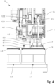
- Fig. 4 is a detailed and magnified partial view of the system S according to Fig. 3 , showing the interactions of the pipetting devices 4.1, 4.2 as well as of the blowing element 7 with a first support element 3.1.
- disposable tips 6.1, 6.2 are attached to the connectors 5.1, 5.2 of both pipetting devices 4.1, 4.2.
- the disposable tips 6.1, 6.2 of both pipetting devices 4.1, 4.2 are inserted into storage vessels of the first support element 3.1.
- the blowing element 7 is positioned on a top surface of the first support element 3.1, wherein each of the apertures of the blowing element 7 are aligned with a well of the first support element 3.1 (see Fig. 5 for details).
- Fig. 5 is a more detailed partial cut-away view of Fig. 4 focussing onto the first support element 3.1.
- the first support element 3.1 comprises a housing 22 and eight wells 17 (of which only one comprises reference numbers for representational reasons).
- Each well 17 has an opening 19 connecting the respective well 17 with a waste tank 18 located beneath the well 17.
- the opening 19 is shaped and dimensioned such that a flow of liquid through said opening 19 is prevented by the surface tension of the liquid.
- each opening 19 has an outlet 20 extending into the respective waste tank 18.
- the wells 17 are open on a top surface of the first support element 3.1. As shown, a probe 24 is present in each of the wells 17.
- the first support element 3.1 comprises five storage vessels 21 (of which only four are shown in the cut-away due to the selection of the cut-away plane).
- Each storage vessel 21 comprises a solution 23, such as a reagent solution, wash solution and/or dilution solution used for a specific assay.
- a support element 3 with such a configuration may also be referred to as cartridge, since it comprises all the necessary solutions as well as wells 17 to carry out a specific assay or assays, even including waste tanks 18 to hold waste liquid resulting from the assay or assays. After completion of the assay or assays the cartridge may be removed and discarded.
- a solution 23 present in the storage vessels 21 is being aspirated into the disposable tips 6.1, 6.2 of the pipetting devices 4.1, 4.2.
- the blowing element is in contact with an upper surface of the first support element 3.1 such that each of the eight apertures 8 is aligned with a well 17 of the first support element 3.1.
- a pressurized gas is being delivered through the apertures 8 into the wells 17, leading to an outflow of liquid through the apertures 19 into the respective waste tanks 18.
- Fig. 6 shows a top view of an embodiment of a support element 3 used in connection with a system S and a fluid delivery device 1 according to the present invention.
- the support element 3 comprises a housing 22 with a cuboid shape. Viewed from top, the housing 22 is of rectangular shape.
- Eight wells 17.1 - 17.8 are arranged in the housing 22 of the support element 3, each well 17.1 - 17.8 having a basic rectangular shape with one of the short sides being in the shape of a half-circle.
- Each well 17.1 - 17.8 comprises a flat bottom surface 25.1 - 25.8 onto which at least one biological binding agent, preferably a multiplicity of biological binding agents are arranged in a matrix.
- Each of the wells 17.1 - 17.8 comprises an aperture 8.1 - 8.8 which connects the respective well 17.1 - 17.8 to a waste tank.
- the support element 3 includes five storage vessels 21.1 - 21.5.
- a first storage vessel 21.1 has a larger size than the other four storage vessels 21.2 - 21.5.
- the first storage vessel 21.1 contains a wash solution which is used in greater quantity than any of the reagent solutions and/or dilutions solutions contained in the other four storage vessels 21.2 - 21.5.
Landscapes
- Chemical & Material Sciences (AREA)
- Health & Medical Sciences (AREA)
- Clinical Laboratory Science (AREA)
- Chemical Kinetics & Catalysis (AREA)
- Analytical Chemistry (AREA)
- General Health & Medical Sciences (AREA)
- Hematology (AREA)
- Human Computer Interaction (AREA)
- Engineering & Computer Science (AREA)
- Life Sciences & Earth Sciences (AREA)
- Biochemistry (AREA)
- General Physics & Mathematics (AREA)
- Immunology (AREA)
- Pathology (AREA)
- Physics & Mathematics (AREA)
- Automatic Analysis And Handling Materials Therefor (AREA)
Claims (16)
- Dispositif de distribution de fluide (1) comprenant au moins une zone (2) sur laquelle un élément de support (3) comprenant au moins un puits (17) peut être placé dans une position définie, le dispositif de distribution de fluide (1) comprenant en outre au moins un dispositif de pipetage (4), ledit au moins un dispositif de pipetage (4) comprenant un connecteur (5) pour connecter de manière amovible ledit au moins un dispositif de pipetage (4) à un embout jetable (6) ainsi qu'un élément de déplacement de fluide qui permet l'aspiration et l'éjection d'un volume défini de liquide vers ou depuis ledit embout jetable (6), ledit au moins un dispositif de pipetage (4) étant mobile dans une direction verticale et de préférence dans au moins une direction horizontale, dans lequel ledit dispositif de distribution de fluide (1) comprend en outre un élément de soufflage (7) avec plus d'une ouverture (8 ; 8.1 à 8.6) couplée à une source de gaz sous pression (10), ledit au moins un élément de soufflage (7) étant mobile dans une direction verticale et de préférence dans au moins une direction horizontale, caractérisé en ce que chacune des ouvertures (8 ; 8.1 à 8.6) est connectée au moyen d'un tube à une soupape courante qui à son tour est connectée à la source de gaz sous pression (10), dans lequel chaque tube comprend un capteur de pression.
- Dispositif de distribution de fluide (1) selon la revendication 1, caractérisé en ce qu'une lèvre d'étanchéité (9 ; 9.1 à 9.6) est disposée autour de ladite au moins une ouverture (8 ; 8.1 à 8.6) dudit élément de soufflage (7).
- Dispositif de distribution de fluide (1) selon l'une quelconque des revendications 1 ou 2, caractérisé en ce que ledit dispositif de distribution de fluide (1) comprend plus d'un dispositif de pipetage (4), de préférence deux, trois, quatre dispositifs de pipetage (4) ou plus.
- Dispositif de distribution de fluide (1) selon l'une quelconque des revendications 1 à 3, caractérisé en ce que ledit élément de soufflage (7) comprend entre 4 et 10 ouvertures (8 ; 8.1 à 8.6), plus préférablement 8 ouvertures (8 ; 8.1 à 8.6).
- Dispositif de distribution de fluide (1) selon l'une quelconque des revendications 1 à 4, caractérisé en ce que ladite source de gaz sous pression est un compresseur d'air (10), de préférence fournissant de l'air avec une pression allant jusqu'à 5 bars.
- Dispositif de distribution de fluide (1) selon l'une quelconque des revendications 1 à 5, caractérisé en ce que le dispositif de distribution de fluide (1) comprend un régulateur électropneumatique disposé entre ladite source de gaz sous pression (10) et ladite au moins une ouverture (8 ; 8.1 à 8.6) afin de réguler la pression du gaz sous pression fourni par ladite source de gaz sous pression (10) à ladite au moins une ouverture (8 ; 8.1 à 8.6).
- Dispositif de distribution de fluide (1) selon l'une quelconque des revendications 1 à 6, caractérisé en ce que le dispositif de distribution de fluide (1) comprend au moins un actionneur (12 ; 12.1 à 12.3) sur lequel ledit au moins un dispositif de pipetage (4) et ledit au moins un élément de soufflage (7) sont fixés.
- Dispositif de distribution de fluide (1) selon l'une quelconque des revendications 1 à 6, caractérisé en ce que le dispositif de distribution de fluide (1) comprend au moins deux actionneurs (12.1 à 12.3), dans lequel l'au moins un dispositif de pipetage (4) est fixé à un premier desdits au moins deux actionneurs (12.1 à 12.3) et ledit au moins un élément de soufflage (7) est fixé à un deuxième desdits au moins deux actionneurs (12.1 à 12.3).
- Dispositif de distribution de fluide (1) selon l'une quelconque des revendications 1 à 6, caractérisé en ce que l'au moins un dispositif de pipetage (4) et l'au moins un élément de soufflage (7) sont fixés chacun à un actionneur (12.1 12.3), lesdits actionneurs (12.1 à 12.3) déplaçant l'au moins un dispositif de pipetage (4) et l'au moins un élément de soufflage (7) dans la direction verticale, dans lequel les actionneurs (12.1 à 12.3) sont fixés à une tête (14), la tête (14) étant mobile dans l'au moins une direction horizontale au moyen d'un portique (15).
- Système comprenant un dispositif de distribution de fluide (1) selon l'une quelconque des revendications 1 à 9 ainsi qu'au moins un élément de support (3) disposé sur ladite au moins une zone (2), ledit au moins un élément de support (3) comprenant au moins un puits (17) avec une surface inférieure dans laquelle un liquide peut être introduit, ainsi qu'au moins un réservoir de déchets (18) disposé sous ledit au moins un puits (17), dans lequel le puits (17) comprend au moins une ouverture (19) sur ladite surface inférieure connectant l'au moins un puits (17) à l'au moins un réservoir de déchets (18), ladite ouverture (19) étant configurée de telle sorte qu'un liquide introduit dans ledit au moins un puits (17) s'écoule uniquement à travers l'ouverture (19) dans le réservoir de déchets (18) lorsqu'un gaz sous pression est distribué dans ledit au moins un puits (17).
- Système selon la revendication 10, caractérisé en ce que ledit au moins un élément de support (3) comprend en outre au moins un récipient de stockage (21) comprenant une solution de réactif, une solution de lavage et/ou une solution de dilution.
- Système selon la revendication 11, caractérisé en ce que le nombre de récipients de stockage (21) dudit élément de support (3) est tel que toutes les solutions de réactif, solutions de lavage et/ou solutions de dilution nécessaires pour réaliser un dosage spécifique dans ledit au moins un puits (17) sont présentes dans ledit élément de support (3).
- Système selon l'une quelconque des revendications 10 à 11, caractérisé en ce que le nombre d'ouvertures (8 ; 8.1 à 8.6) dudit élément de soufflage (7) correspond au nombre de puits (17) de l'élément de support (3).
- Système selon l'une quelconque des revendications 10 à 13, caractérisé en ce qu'une lèvre d'étanchéité (9 ; 9.1 à 9.6) ayant une forme épousant la forme de l'au moins un puits (17) est disposée autour de ladite au moins une ouverture (8 ; 8.1 à 8.6).
- Système selon l'une quelconque des revendications 10 à 14, caractérisé en ce que ladite au moins une ouverture (19) a une dimension et une forme qui sont telles qu'un écoulement d'un liquide présent dans le puits (17) à travers ladite ouverture (19) est empêché par une tension de surface dudit liquide.
- Procédé de réalisation d'un dosage chimique ou biologique avec un système selon l'une quelconque des revendications 10 à 15, comprenant les étapes suivantes :a) disposer un élément de support (3) avec au moins un puits (17) sur ladite au moins une zone (2), ledit au moins un puits (17) ayant une surface inférieure avec une ouverture (19), ladite ouverture (19) étant configurée de telle sorte qu'un liquide introduit dans ledit au moins un puits (17) s'écoule uniquement à travers l'ouverture (19) dans le réservoir de déchets (18) disposé dans l'élément de support (3) sous ledit au moins un puits (17) lorsqu'un gaz sous pression est délivré dans ledit au moins un puits (17) ;b) délivrer au moins un liquide dans ledit au moins un puits (17) au moyen de l'au moins un dispositif de pipetage (4) ;c) déplacer l'élément de soufflage (7) sur ledit élément de support (3) de telle sorte que l'au moins une ouverture (8; 8.1 à 8.6) est positionnée sur ledit au moins un puits (17) après une période de temps définie ;d) délivrer un volume défini de gaz sous pression à travers ladite au moins une ouverture (8 ; 8.1 à 8.6) afin de pousser l'au moins un liquide à travers l'ouverture (19) dans l'au moins un réservoir de déchets (18).
Applications Claiming Priority (1)
| Application Number | Priority Date | Filing Date | Title |
|---|---|---|---|
| PCT/EP2019/053995 WO2020169176A1 (fr) | 2019-02-18 | 2019-02-18 | Dispositif de distribution de fluide et procédé pour effectuer des dosages chimiques ou biologiques |
Publications (3)
| Publication Number | Publication Date |
|---|---|
| EP3927468A1 EP3927468A1 (fr) | 2021-12-29 |
| EP3927468C0 EP3927468C0 (fr) | 2025-05-07 |
| EP3927468B1 true EP3927468B1 (fr) | 2025-05-07 |
Family
ID=65520256
Family Applications (1)
| Application Number | Title | Priority Date | Filing Date |
|---|---|---|---|
| EP19706940.4A Active EP3927468B1 (fr) | 2019-02-18 | 2019-02-18 | Dispositif de distribution de fluide et procédé pour effectuer des dosages chimiques ou biologiques |
Country Status (3)
| Country | Link |
|---|---|
| US (1) | US12172154B2 (fr) |
| EP (1) | EP3927468B1 (fr) |
| WO (1) | WO2020169176A1 (fr) |
Families Citing this family (2)
| Publication number | Priority date | Publication date | Assignee | Title |
|---|---|---|---|---|
| WO2024082187A1 (fr) * | 2022-10-19 | 2024-04-25 | 深圳华大生命科学研究院 | Système de pipetage pour puce fluidique, et procédé de pipetage pour puce fluidique |
| EP4713143A1 (fr) * | 2023-05-19 | 2026-03-25 | Opentrons Labworks Inc. | Système et procédé d'étalonnage de détection de surface |
Family Cites Families (14)
| Publication number | Priority date | Publication date | Assignee | Title |
|---|---|---|---|---|
| US4090850A (en) | 1976-11-01 | 1978-05-23 | E. R. Squibb & Sons, Inc. | Apparatus for use in radioimmunoassays |
| US5472672A (en) | 1993-10-22 | 1995-12-05 | The Board Of Trustees Of The Leland Stanford Junior University | Apparatus and method for polymer synthesis using arrays |
| US5948359A (en) | 1997-03-21 | 1999-09-07 | Biogenex Laboratories | Automated staining apparatus |
| JP2007526479A (ja) * | 2004-03-02 | 2007-09-13 | ダコ デンマーク アクティーゼルスカブ | 生物学的染色装置のための試薬送達システム、分配デバイスおよび容器 |
| US7455814B2 (en) | 2004-04-23 | 2008-11-25 | Giblin Leonard J | Metered dispenser and aspirator device |
| AU2005252242A1 (en) * | 2004-06-07 | 2005-12-22 | Irm Llc | Dispensing systems, software, and related methods |
| US9551635B2 (en) | 2006-03-09 | 2017-01-24 | Biogenex Laboratories Inc. | Sample processing system |
| US20090004754A1 (en) | 2007-06-26 | 2009-01-01 | Oldenburg Kevin R | Multi-well reservoir plate and methods of using same |
| CA3138078C (fr) | 2007-10-02 | 2024-02-13 | Labrador Diagnostics Llc | Dispositifs modulaires a utiliser sur place et leurs utilisations |
| CN102483424B (zh) | 2009-06-26 | 2014-11-05 | 哈佛学院院长等 | 用于流体操作的方法以及微流体装置 |
| JP5646196B2 (ja) * | 2010-03-30 | 2014-12-24 | 武蔵エンジニアリング株式会社 | 吐出装置および液体分注装置並びに液体分注方法 |
| WO2017027425A1 (fr) * | 2015-08-10 | 2017-02-16 | Counsyl, Inc. | Système modulaire de manipulation de liquides |
| US10864515B2 (en) * | 2016-11-11 | 2020-12-15 | Walid Habbal | Automated pipette manipulation system |
| ES2781880T3 (es) | 2017-08-18 | 2020-09-08 | Ctc Analytics Ag | Cartucho para ensayos químicos o biológicos |
-
2019
- 2019-02-18 EP EP19706940.4A patent/EP3927468B1/fr active Active
- 2019-02-18 WO PCT/EP2019/053995 patent/WO2020169176A1/fr not_active Ceased
- 2019-02-18 US US17/431,518 patent/US12172154B2/en active Active
Also Published As
| Publication number | Publication date |
|---|---|
| EP3927468C0 (fr) | 2025-05-07 |
| US12172154B2 (en) | 2024-12-24 |
| EP3927468A1 (fr) | 2021-12-29 |
| US20220126285A1 (en) | 2022-04-28 |
| WO2020169176A1 (fr) | 2020-08-27 |
Similar Documents
| Publication | Publication Date | Title |
|---|---|---|
| US7159740B2 (en) | Method and apparatus for parallel dispensing of defined volumes of solid particles | |
| EP1434055B1 (fr) | Système de distribution de billes | |
| US11524287B2 (en) | Automatic pipetting device for transferring samples and/or reagents and method for transferring liquid samples and/or reagents | |
| EP1256808B1 (fr) | Systeme de transfert et de traitement de receptacles | |
| US8142719B2 (en) | Analysis device | |
| AU578123B2 (en) | Automated assay machine and assay tray | |
| US20030026732A1 (en) | Continuous processing automated workstation | |
| US9095833B2 (en) | System for performing automated solid phase extractions | |
| EP0589899A1 (fr) | Appareil et procede ameliores permettant la distribution de serum sanguin ou de plasma sanguin | |
| EP2058666A1 (fr) | Separateur de microplaque et procede de separation de microplaque | |
| EP3444033B1 (fr) | Cartouche pour des dosages chimiques ou biologiques | |
| US8029744B2 (en) | Method of liquid droplet formation and transport apparatus therefor and particle manipulating apparatus | |
| JP2004513761A (ja) | 自動計量分配貯蔵装置 | |
| EP3927468B1 (fr) | Dispositif de distribution de fluide et procédé pour effectuer des dosages chimiques ou biologiques | |
| US5322192A (en) | Pipetting apparatus | |
| WO2003035260A1 (fr) | Procede et appareil a haut rendement pour chaine de traitement de manipulation d'echantillons | |
| AU2002348095A1 (en) | Method and apparatus for parallel dispensing of defined volumes of solid particles | |
| AU2002342186A1 (en) | Method and apparatus for high-throughput sample handling process line |
Legal Events
| Date | Code | Title | Description |
|---|---|---|---|
| STAA | Information on the status of an ep patent application or granted ep patent |
Free format text: STATUS: UNKNOWN |
|
| STAA | Information on the status of an ep patent application or granted ep patent |
Free format text: STATUS: THE INTERNATIONAL PUBLICATION HAS BEEN MADE |
|
| PUAI | Public reference made under article 153(3) epc to a published international application that has entered the european phase |
Free format text: ORIGINAL CODE: 0009012 |
|
| STAA | Information on the status of an ep patent application or granted ep patent |
Free format text: STATUS: REQUEST FOR EXAMINATION WAS MADE |
|
| 17P | Request for examination filed |
Effective date: 20210816 |
|
| AK | Designated contracting states |
Kind code of ref document: A1 Designated state(s): AL AT BE BG CH CY CZ DE DK EE ES FI FR GB GR HR HU IE IS IT LI LT LU LV MC MK MT NL NO PL PT RO RS SE SI SK SM TR |
|
| DAV | Request for validation of the european patent (deleted) | ||
| DAX | Request for extension of the european patent (deleted) | ||
| P01 | Opt-out of the competence of the unified patent court (upc) registered |
Effective date: 20230515 |
|
| STAA | Information on the status of an ep patent application or granted ep patent |
Free format text: STATUS: EXAMINATION IS IN PROGRESS |
|
| 17Q | First examination report despatched |
Effective date: 20240717 |
|
| GRAP | Despatch of communication of intention to grant a patent |
Free format text: ORIGINAL CODE: EPIDOSNIGR1 |
|
| STAA | Information on the status of an ep patent application or granted ep patent |
Free format text: STATUS: GRANT OF PATENT IS INTENDED |
|
| INTG | Intention to grant announced |
Effective date: 20250108 |
|
| GRAS | Grant fee paid |
Free format text: ORIGINAL CODE: EPIDOSNIGR3 |
|
| GRAA | (expected) grant |
Free format text: ORIGINAL CODE: 0009210 |
|
| STAA | Information on the status of an ep patent application or granted ep patent |
Free format text: STATUS: THE PATENT HAS BEEN GRANTED |
|
| AK | Designated contracting states |
Kind code of ref document: B1 Designated state(s): AL AT BE BG CH CY CZ DE DK EE ES FI FR GB GR HR HU IE IS IT LI LT LU LV MC MK MT NL NO PL PT RO RS SE SI SK SM TR |
|
| REG | Reference to a national code |
Ref country code: GB Ref legal event code: FG4D |
|
| REG | Reference to a national code |
Ref country code: CH Ref legal event code: EP |
|
| REG | Reference to a national code |
Ref country code: DE Ref legal event code: R096 Ref document number: 602019069585 Country of ref document: DE |
|
| REG | Reference to a national code |
Ref country code: IE Ref legal event code: FG4D |
|
| P04 | Withdrawal of opt-out of the competence of the unified patent court (upc) registered |
Free format text: CASE NUMBER: APP_23854/2025 Effective date: 20250519 |
|
| U01 | Request for unitary effect filed |
Effective date: 20250516 |
|
| U07 | Unitary effect registered |
Designated state(s): AT BE BG DE DK EE FI FR IT LT LU LV MT NL PT RO SE SI Effective date: 20250522 |
|
| PG25 | Lapsed in a contracting state [announced via postgrant information from national office to epo] |
Ref country code: ES Free format text: LAPSE BECAUSE OF FAILURE TO SUBMIT A TRANSLATION OF THE DESCRIPTION OR TO PAY THE FEE WITHIN THE PRESCRIBED TIME-LIMIT Effective date: 20250507 |
|
| PG25 | Lapsed in a contracting state [announced via postgrant information from national office to epo] |
Ref country code: NO Free format text: LAPSE BECAUSE OF FAILURE TO SUBMIT A TRANSLATION OF THE DESCRIPTION OR TO PAY THE FEE WITHIN THE PRESCRIBED TIME-LIMIT Effective date: 20250807 Ref country code: GR Free format text: LAPSE BECAUSE OF FAILURE TO SUBMIT A TRANSLATION OF THE DESCRIPTION OR TO PAY THE FEE WITHIN THE PRESCRIBED TIME-LIMIT Effective date: 20250808 |
|
| PG25 | Lapsed in a contracting state [announced via postgrant information from national office to epo] |
Ref country code: PL Free format text: LAPSE BECAUSE OF FAILURE TO SUBMIT A TRANSLATION OF THE DESCRIPTION OR TO PAY THE FEE WITHIN THE PRESCRIBED TIME-LIMIT Effective date: 20250507 |
|
| PG25 | Lapsed in a contracting state [announced via postgrant information from national office to epo] |
Ref country code: HR Free format text: LAPSE BECAUSE OF FAILURE TO SUBMIT A TRANSLATION OF THE DESCRIPTION OR TO PAY THE FEE WITHIN THE PRESCRIBED TIME-LIMIT Effective date: 20250507 |
|
| PG25 | Lapsed in a contracting state [announced via postgrant information from national office to epo] |
Ref country code: RS Free format text: LAPSE BECAUSE OF FAILURE TO SUBMIT A TRANSLATION OF THE DESCRIPTION OR TO PAY THE FEE WITHIN THE PRESCRIBED TIME-LIMIT Effective date: 20250807 |
|
| PG25 | Lapsed in a contracting state [announced via postgrant information from national office to epo] |
Ref country code: IS Free format text: LAPSE BECAUSE OF FAILURE TO SUBMIT A TRANSLATION OF THE DESCRIPTION OR TO PAY THE FEE WITHIN THE PRESCRIBED TIME-LIMIT Effective date: 20250907 |
|
| PG25 | Lapsed in a contracting state [announced via postgrant information from national office to epo] |
Ref country code: SM Free format text: LAPSE BECAUSE OF FAILURE TO SUBMIT A TRANSLATION OF THE DESCRIPTION OR TO PAY THE FEE WITHIN THE PRESCRIBED TIME-LIMIT Effective date: 20250507 |
|
| PG25 | Lapsed in a contracting state [announced via postgrant information from national office to epo] |
Ref country code: CZ Free format text: LAPSE BECAUSE OF FAILURE TO SUBMIT A TRANSLATION OF THE DESCRIPTION OR TO PAY THE FEE WITHIN THE PRESCRIBED TIME-LIMIT Effective date: 20250507 |
|
| PG25 | Lapsed in a contracting state [announced via postgrant information from national office to epo] |
Ref country code: SK Free format text: LAPSE BECAUSE OF FAILURE TO SUBMIT A TRANSLATION OF THE DESCRIPTION OR TO PAY THE FEE WITHIN THE PRESCRIBED TIME-LIMIT Effective date: 20250507 |
|
| REG | Reference to a national code |
Ref country code: CH Ref legal event code: U11 Free format text: ST27 STATUS EVENT CODE: U-0-0-U10-U11 (AS PROVIDED BY THE NATIONAL OFFICE) Effective date: 20260301 |
|
| PLBE | No opposition filed within time limit |
Free format text: ORIGINAL CODE: 0009261 |
|
| STAA | Information on the status of an ep patent application or granted ep patent |
Free format text: STATUS: NO OPPOSITION FILED WITHIN TIME LIMIT |
|
| REG | Reference to a national code |
Ref country code: CH Ref legal event code: L10 Free format text: ST27 STATUS EVENT CODE: U-0-0-L10-L00 (AS PROVIDED BY THE NATIONAL OFFICE) Effective date: 20260318 |
|
| U20 | Renewal fee for the european patent with unitary effect paid |
Year of fee payment: 8 Effective date: 20260225 |
|
| 26N | No opposition filed |
Effective date: 20260210 |
|
| PGFP | Annual fee paid to national office [announced via postgrant information from national office to epo] |
Ref country code: CH Payment date: 20260301 Year of fee payment: 8 |