EP3928034B1 - Chambre de combustion pour une turbomachine - Google Patents
Chambre de combustion pour une turbomachine Download PDFInfo
- Publication number
- EP3928034B1 EP3928034B1 EP20721283.8A EP20721283A EP3928034B1 EP 3928034 B1 EP3928034 B1 EP 3928034B1 EP 20721283 A EP20721283 A EP 20721283A EP 3928034 B1 EP3928034 B1 EP 3928034B1
- Authority
- EP
- European Patent Office
- Prior art keywords
- injection system
- combustion chamber
- sleeve
- bottom wall
- baffle
- Prior art date
- Legal status (The legal status is an assumption and is not a legal conclusion. Google has not performed a legal analysis and makes no representation as to the accuracy of the status listed.)
- Active
Links
Images



Classifications
-
- F—MECHANICAL ENGINEERING; LIGHTING; HEATING; WEAPONS; BLASTING
- F23—COMBUSTION APPARATUS; COMBUSTION PROCESSES
- F23R—GENERATING COMBUSTION PRODUCTS OF HIGH PRESSURE OR HIGH VELOCITY, e.g. GAS-TURBINE COMBUSTION CHAMBERS
- F23R3/00—Continuous combustion chambers using liquid or gaseous fuel
- F23R3/28—Continuous combustion chambers using liquid or gaseous fuel characterised by the fuel supply
- F23R3/283—Attaching or cooling of fuel injecting means including supports for fuel injectors, stems, or lances
-
- F—MECHANICAL ENGINEERING; LIGHTING; HEATING; WEAPONS; BLASTING
- F02—COMBUSTION ENGINES; HOT-GAS OR COMBUSTION-PRODUCT ENGINE PLANTS
- F02C—GAS-TURBINE PLANTS; AIR INTAKES FOR JET-PROPULSION PLANTS; CONTROLLING FUEL SUPPLY IN AIR-BREATHING JET-PROPULSION PLANTS
- F02C3/00—Gas-turbine plants characterised by the use of combustion products as the working fluid
-
- F—MECHANICAL ENGINEERING; LIGHTING; HEATING; WEAPONS; BLASTING
- F23—COMBUSTION APPARATUS; COMBUSTION PROCESSES
- F23R—GENERATING COMBUSTION PRODUCTS OF HIGH PRESSURE OR HIGH VELOCITY, e.g. GAS-TURBINE COMBUSTION CHAMBERS
- F23R3/00—Continuous combustion chambers using liquid or gaseous fuel
- F23R3/42—Continuous combustion chambers using liquid or gaseous fuel characterised by the arrangement or form of the flame tubes or combustion chambers
- F23R3/50—Combustion chambers comprising an annular flame tube within an annular casing
-
- F—MECHANICAL ENGINEERING; LIGHTING; HEATING; WEAPONS; BLASTING
- F23—COMBUSTION APPARATUS; COMBUSTION PROCESSES
- F23R—GENERATING COMBUSTION PRODUCTS OF HIGH PRESSURE OR HIGH VELOCITY, e.g. GAS-TURBINE COMBUSTION CHAMBERS
- F23R3/00—Continuous combustion chambers using liquid or gaseous fuel
- F23R3/42—Continuous combustion chambers using liquid or gaseous fuel characterised by the arrangement or form of the flame tubes or combustion chambers
- F23R3/60—Support structures; Attaching or mounting means
-
- F—MECHANICAL ENGINEERING; LIGHTING; HEATING; WEAPONS; BLASTING
- F05—INDEXING SCHEMES RELATING TO ENGINES OR PUMPS IN VARIOUS SUBCLASSES OF CLASSES F01-F04
- F05D—INDEXING SCHEME FOR ASPECTS RELATING TO NON-POSITIVE-DISPLACEMENT MACHINES OR ENGINES, GAS-TURBINES OR JET-PROPULSION PLANTS
- F05D2220/00—Application
- F05D2220/30—Application in turbines
- F05D2220/32—Application in turbines in gas turbines
-
- F—MECHANICAL ENGINEERING; LIGHTING; HEATING; WEAPONS; BLASTING
- F05—INDEXING SCHEMES RELATING TO ENGINES OR PUMPS IN VARIOUS SUBCLASSES OF CLASSES F01-F04
- F05D—INDEXING SCHEME FOR ASPECTS RELATING TO NON-POSITIVE-DISPLACEMENT MACHINES OR ENGINES, GAS-TURBINES OR JET-PROPULSION PLANTS
- F05D2230/00—Manufacture
- F05D2230/60—Assembly methods
-
- F—MECHANICAL ENGINEERING; LIGHTING; HEATING; WEAPONS; BLASTING
- F05—INDEXING SCHEMES RELATING TO ENGINES OR PUMPS IN VARIOUS SUBCLASSES OF CLASSES F01-F04
- F05D—INDEXING SCHEME FOR ASPECTS RELATING TO NON-POSITIVE-DISPLACEMENT MACHINES OR ENGINES, GAS-TURBINES OR JET-PROPULSION PLANTS
- F05D2240/00—Components
- F05D2240/35—Combustors or associated equipment
-
- F—MECHANICAL ENGINEERING; LIGHTING; HEATING; WEAPONS; BLASTING
- F16—ENGINEERING ELEMENTS AND UNITS; GENERAL MEASURES FOR PRODUCING AND MAINTAINING EFFECTIVE FUNCTIONING OF MACHINES OR INSTALLATIONS; THERMAL INSULATION IN GENERAL
- F16B—DEVICES FOR FASTENING OR SECURING CONSTRUCTIONAL ELEMENTS OR MACHINE PARTS TOGETHER, e.g. NAILS, BOLTS, CIRCLIPS, CLAMPS, CLIPS OR WEDGES; JOINTS OR JOINTING
- F16B5/00—Joining sheets or plates, e.g. panels, to one another or to strips or bars parallel to them
- F16B5/10—Joining sheets or plates, e.g. panels, to one another or to strips or bars parallel to them by means of bayonet connections
-
- F—MECHANICAL ENGINEERING; LIGHTING; HEATING; WEAPONS; BLASTING
- F23—COMBUSTION APPARATUS; COMBUSTION PROCESSES
- F23R—GENERATING COMBUSTION PRODUCTS OF HIGH PRESSURE OR HIGH VELOCITY, e.g. GAS-TURBINE COMBUSTION CHAMBERS
- F23R2900/00—Special features of, or arrangements for continuous combustion chambers; Combustion processes therefor
- F23R2900/00005—Preventing fatigue failures or reducing mechanical stress in gas turbine components
-
- F—MECHANICAL ENGINEERING; LIGHTING; HEATING; WEAPONS; BLASTING
- F23—COMBUSTION APPARATUS; COMBUSTION PROCESSES
- F23R—GENERATING COMBUSTION PRODUCTS OF HIGH PRESSURE OR HIGH VELOCITY, e.g. GAS-TURBINE COMBUSTION CHAMBERS
- F23R2900/00—Special features of, or arrangements for continuous combustion chambers; Combustion processes therefor
- F23R2900/00017—Assembling combustion chamber liners or subparts
Definitions
- the invention relates to a combustion chamber for a turbomachine, such as an aircraft turbojet or turboprop.
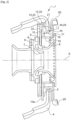
- FIG. 1 represents part of an annular combustion chamber 1 of a turbomachine such as a turbojet or an airplane turboprop, in accordance with the prior art.
- Combustion chamber 1 is arranged at the outlet of a diffuser, not shown, itself located at the outlet of a compressor.
- Chamber 1 comprises an internal wall of revolution 2 and an external wall of revolution 3, connected upstream by an annular wall at the bottom of the chamber 4.
- the chamber bottom wall 4 has openings 5 in which are mounted systems 6 for injecting a mixture of air and fuel into the chamber 1, the air coming from the diffuser and the fuel being supplied by injectors (not shown) regularly distributed over the circumference of the combustion chamber 1.
- Each injector comprises a fuel injection head aligned on the axis A of the corresponding opening 5.
- Part of the air flow supplied by the compressor and leaving the diffuser feeds internal and external annular ducts for bypassing the combustion chamber.
- the other part of the air flow enters the injection system and is then mixed with the fuel supplied by the injectors before being sprayed into the combustion chamber 1.
- a central fuel injector is surrounded by an annular wall 7 of said injection system 6 forming a venturi.
- a bowl 8 surrounds the annular wall, said bowl 8 widening out downstream.
- the injection system 6 conventionally comprises fins 9 intended to impart to the flow of air passing through it a gyration movement favoring the homogenization of the mixture of air and fuel.
- the radially outer periphery of the bowl has a radial rim 10 movably mounted in a radial groove 11 delimited by a sleeve 12 welded to the bottom wall 4 of the combustion chamber 1 and by a closing ring 13 welded to the sleeve 12.
- the radial displacement of the flange 10 in the groove 11 makes it possible to compensate for the relative displacements between the injectors and the casing of the turbomachine on which they are fixed, on the one hand, and the combustion chamber 1, on the other hand. Such displacements appear in operation due to the differential expansions between the various elements of the turbomachine.
- a deflector 14 is also mounted downstream of the bottom wall 4, the deflector 14 comprising a cylindrical part 15 mounted inside a cylindrical part 16 of the sleeve 12 and fixed by brazing or welding to said cylindrical part 16 of the scabbard 12.
- the deflector and the injection system thus comprise a bayonet-type system allowing the injection system to be mounted in the deflector, in the first angular position, and maintaining the deflector axially with respect to the injection system, in the second position. angular.
- the deflector remains held axially by the projecting part, so that there is no no risk of damaging elements of the turbomachine which are located downstream.
- upstream and downstream are defined with respect to the flow of gas circulating in the combustion chamber.
- radial, axial and circumferential are defined with respect to the axis of the injection system.
- the combustion chamber may comprise means for maintaining in position able to maintain the injection system in its second position with respect to the deflector
- the projecting part can extend radially from the downstream end of the injection system, the recessed part being formed in the deflector.
- the projecting part is for example formed by a lug or a lug extending radially outwards.
- the recessed part is for example formed by a groove or a notch in the deflector.
- the number of projecting parts and recessed parts is for example equal to three.
- the protruding and recessed parts can then be evenly distributed over the circumference.
- the injection system may include a rotation locking lug maintained or immobilized in rotation by circumferential stops of the sheath and/or of the closure ring.
- the sheath may comprise a first circumferential stop and a second circumferential stop, the rotation-blocking lug being able to bear against the first circumferential stop in the first angular position of the injection system, the rotation-blocking lug being able to bear against the second circumferential stop in the second angular position of the injection system.
- the circumferential stops thus form limit stops, authorizing and limiting the angular movement of the injection system with respect to the deflector.
- Such a structure facilitates assembly of the assembly.
- the closure ring may include a third circumferential stop, the lug being capable of being held in position between the second and third circumferential stops, so as to hold the injection system in its second angular position.
- the second and third circumferential stops thus form the aforementioned means for holding in position, with the lug for holding in position.
- the sheath may comprise a radially internal cylindrical part, mounted in the opening of the bottom wall and fixed to the periphery of said opening.
- the corresponding fixing is for example ensured by brazing or welding.
- the deflector may comprise a cylindrical part mounted in the radially internal cylindrical part of the sheath and fixed to said radially internal cylindrical part.
- the corresponding fixing is for example ensured by brazing or welding.
- the sheath may comprise a radially outer cylindrical part, located axially upstream of the radially inner cylindrical part, the closure ring being mounted radially inside the radially outer cylindrical part.
- the combustion chamber may comprise an injector comprising an injection head mounted in the injection system, the injection system comprising means for supplying air and means for forming a mixture of air with the fuel from the injector.
- the invention also relates to a turbomachine comprising a combustion chamber of the aforementioned type.
- THE figures 2 to 8 illustrate part of a combustion chamber 1 according to one embodiment of the invention, intended to equip a turbomachine, such as a turbojet or an airplane turboprop.
- a turbomachine such as a turbojet or an airplane turboprop.
- Chamber 1 comprises an internal wall of revolution and an external wall of revolution, connected upstream by an annular wall at the bottom of chamber 4.
- the chamber bottom wall 4 has openings 5 in which are mounted systems 6 for injecting a mixture of air and fuel into the chamber 1, the air coming from the diffuser and the fuel being supplied by injectors (not shown) regularly distributed over the circumference of the combustion chamber 1.
- Each injector comprises a fuel injection head aligned on the axis A of the corresponding opening 5.
- Part of the air flow supplied by the compressor and leaving the diffuser feeds internal and external annular ducts for bypassing the combustion chamber.
- the other part of the air flow enters the injection system and is then mixed with the fuel supplied by the injectors before being sprayed into the combustion chamber 1.
- a central fuel injector is surrounded by an annular wall 7 of said injection system 6 forming a venturi.
- a bowl 8 surrounds the annular wall, said bowl 8 widening out downstream.
- the downstream end of bowl 8 has an annular rim 17 extending radially outwards.
- lugs or lugs 18 extend radially outwards from the radially outer periphery of the annular flange 17.
- the lugs here are three in number and are regularly distributed over the circumference, that is to say are staggered angularly relative to each other by an angle of 120°.
- the injection system 6 also conventionally comprises fins 9 intended to impart to the flow of air entering through the channel delimited between the bowl 8 and the annular wall a gyration movement favoring the homogenization of the mixture of air and fuel. .
- the radially outer periphery of the bowl has a radial rim 10 connected to the rim 17 by a cylindrical part 19.
- the rim 10 is located axially upstream of the rim 17.
- the rim 10 is movably mounted in a radial groove 11 delimited by a sheath 12 welded to the bottom wall 4 of the combustion chamber 1 and by a closure ring 13 welded to the sheath 12.
- the flange 10 includes a tab 10a extending radially outwards from the radially outer end of the flange 10 .
- the radial displacement of the flange 10 in the groove 11 makes it possible to compensate for the relative displacements between the injectors and the casing of the turbomachine on which they are fixed, on the one hand, and the combustion chamber 1, on the other hand. Such displacements appear in operation due to the differential expansions between the various elements of the turbomachine,
- sleeve 12 comprises, from upstream to downstream, a cylindrical part 20, a radially extending annular part 21 and a cylindrical part 16.
- the cylindrical part 20 has a larger diameter than the cylindrical part 16.
- cylindrical 16 is mounted in the opening 5 of the bottom wall and is fixed to said bottom wall 4 by welding or brazing.
- the radially inner zone of the radial part 21 includes a downstream bearing surface bearing against the bottom wall 4.
- the cylindrical part 20 extends over only part of the circumference.
- the sheath comprises an angular sector devoid of a cylindrical part 20, as is better visible at the figure 7 , this angular sector here extends over 120°.
- the extremities circumferential 20a, 20b of the cylindrical part 20 are able to form abutments for the tab 10a which is housed in said angular sector devoid of cylindrical part 20.
- the closure ring 13 has a general T-shaped section, comprising a radial part 22 and a cylindrical part 23 which are annular.
- the downstream end of the cylindrical part 23 bears against the radial part 21 of the sleeve 12.
- Said radial part 21 of the sleeve 12 and the radial part 22 of the closure ring 23 are thus spaced axially from each other. and delimit the groove 11 between them.
- the downstream end of the cylindrical part 23 has a notch 23a ( figure 8 ) whose function is explained below.
- a deflector 14 is also mounted downstream of the bottom wall 4.
- the deflector 14 comprises, from upstream to downstream, a cylindrical part 15, a radial part 24 having the shape of a ring sector, and flanges 25 extending axially downstream at the level of the radially internal edges and external part of radial part 24.
- Cylindrical part 15 is mounted inside cylindrical part 16 of sheath 12 and fixed by brazing or welding to said cylindrical part 16.
- the cylindrical part 16 further comprises grooves 26, here three in number, regularly distributed over the circumference.
- the sleeve 12, in particular the cylindrical part 16, is firstly mounted in the opening 5 of the bottom wall 4.
- the deflector 14, in particular the cylindrical part 15, is mounted in the cylindrical part 16 of the sleeve.
- the cylindrical part 16, the cylindrical part 15 and the bottom wall are then assembled together by welding or brazing.
- the injection system is then mounted in the opening 5 of the bottom wall, through the sheath 12 and the deflector 14.
- the injection system is positioned in a first angular position so that the lugs 18 of the injection system 6 are located opposite the grooves 26 of the deflector 14.
- the injection system is then moved in translation downstream, until the rim 10 bears against the radial part 21 of the sheath.
- the lugs 18 are then located just downstream of the radial part 24 of the deflector and the lug 10a is housed in the zone of the sheath 12 devoid of cylindrical rim 20.
- the injection system 16 is then pivoted into a second angular position, illustrated in figures 6 to 8 .
- the injection system is pivoted through an angle of 60° between the first and second angular positions, this angle corresponding to half the angular spacing between two grooves 26 or between two lugs 18.
- the lug 10a of the injection system 6 bears against the circumferential stop 20a, so as to facilitate assembly.
- the lugs 18 are offset from the grooves 26 and are able to bear against the radial part 24 of the deflector 14, so as to prevent the axial displacement of the injection system 6.
- the closure ring 13 is mounted in the cylindrical part 20 of the sheath 10, so that the lug 10a is housed and held in position in the notch 23a.
- the closure ring 13 is then fixed by welding or brazing to the sheath 12.
- the injection system 6 is thus immobilized in rotation.
- Such a structure makes it possible to ensure simple assembly of the assembly while preventing the removal of the deflector 14 in the event of unsoldering or desoldering of the cylindrical part 15. This avoids degradation of the parts of the turbomachine which are located downstream of the bottom wall 4 or the combustion chamber 1.
Landscapes
- Engineering & Computer Science (AREA)
- Chemical & Material Sciences (AREA)
- Combustion & Propulsion (AREA)
- Mechanical Engineering (AREA)
- General Engineering & Computer Science (AREA)
- Fuel-Injection Apparatus (AREA)
- Combustion Methods Of Internal-Combustion Engines (AREA)
Description
- L'invention concerne une chambre de combustion pour une turbomachine, telle qu'un turboréacteur ou un turbopropulseur d'avion.
- La
figure 1 représente une partie d'une chambre de combustion annulaire 1 d'une turbomachine telle qu'un turboréacteur ou un turbopropulseur d'avion, conformément à l'art antérieur. - La chambre de combustion 1 est agencée en sortie d'un diffuseur non représenté, lui-même situé à la sortie d'un compresseur. La chambre 1 comporte une paroi de révolution interne 2 et une paroi de révolution externe 3, reliées en amont par une paroi annulaire de fond de chambre 4.
- La paroi de fond de chambre 4 comporte des ouvertures 5 dans lesquelles sont montés des systèmes d'injection 6 d'un mélange d'air et de carburant dans la chambre 1, l'air provenant du diffuseur et le carburant étant amené par des injecteurs (non représentés) régulièrement répartis sur la circonférence de la chambre de combustion 1. Chaque injecteur comprend une tête d'injection de carburant aligné sur l'axe A de l'ouverture 5 correspondante.
- Une partie du débit d'air fourni par le compresseur et sortant du diffuseur alimente des conduits annulaires interne et externe de contournement de la chambre de combustion. L'autre partie du débit d'air pénètre dans les système d'injection et est ensuite mélangée au carburant amené par les injecteurs avant d'être pulvérisée dans la chambre de combustion 1.
- Pour chaque système d'injection 6, un injecteur de carburant central est entouré par une paroi annulaire 7 dudit système d'injection 6 formant un venturi. Un bol 8 entoure la paroi annulaire, ledit bol 8 s'évasant vers l'aval. Le système d'injection 6 comporte classiquement des ailettes 9 destinées à imprimer au flux d'air le traversant un mouvement de giration favorisant l'homogénéisation du mélange d'air et de carburant.
- La périphérie radialement externe du bol comporte un rebord radial 10 monté de façon mobile dans une gorge radiale 11 délimitée par un fourreau 12 soudé sur la paroi de fond 4 de la chambre de combustion 1 et par une bague de fermeture 13 soudée au fourreau 12.
- Le déplacement radial du rebord 10 dans la gorge 11 permet de compenser les déplacements relatifs entre les injecteurs et le carter de la turbomachine sur lequel ils sont fixés, d'une part, et la chambre de combustion 1, d'autre part. De tels déplacements apparaissent en fonctionnement en raison des dilatations différentielles entre les divers éléments de la turbomachine.
- Un déflecteur 14 est par ailleurs monté en aval de la paroi de fond 4, le déflecteur 14 comportant une partie cylindrique 15 montée à l'intérieur d'une partie cylindrique 16 du fourreau 12 et fixée par brasage ou soudage à ladite partie cylindrique 16 du fourreau 12.
- Il existe un risque que le déflecteur 14 se détache du fourreau 12, et provoque un endommagement des éléments situés en aval, notamment la turbine.
- Le document
US 2019/003711 A1 divulgue une chambre de combustion de l'art antérieur. L'invention vise à éviter un tel endommagement, de manière simple, fiable et peu onéreuse. - A cet effet, l'invention concerne une chambre de combustion de turbomachine, comportant
- une paroi de fond comportant au moins une ouverture,
- au moins un fourreau monté en amont de la paroi de fond et fixé à la paroi de fond,
- une bague de fermeture délimitant une gorge annulaire avec le fourreau et fixée au fourreau,
- au moins un système d'injection d'air et de carburant, présentant un axe, monté dans l'ouverture de la paroi de fond, le système d'injection comprenant un rebord annulaire s'étendant radialement par rapport audit axe, monté dans ladite gorge avec un jeu radial,
- un déflecteur situé en aval de la paroi de fond, fixé au fourreau et/ou à la paroi de fond, comportant une partie radialement interne située axialement entre la paroi de fond et une extrémité aval du système d'injection, le système d'injection comportant au moins une partie en saillie apte à être introduite dans une partie en creux du déflecteur, ou inversement, dans une première position angulaire de montage du système d'injection par rapport au déflecteur, ladite partie en saillie étant apte à venir axialement en butée sur une face radiale du déflecteur, ou respectivement, du système d'injection, dans une seconde position angulaire de maintien du système d'injection par rapport au déflecteur, ladite partie en saillie étant décalée angulairement de la partie en creux dans ladite seconde position.
- Le déflecteur et le système d'injection comportent ainsi un système de type baïonnette permettant le montage de système d'injection dans le déflecteur, dans la première position angulaire, et maintenant axialement le déflecteur par rapport au système d'injection, dans la seconde position angulaire. En cas de séparation du déflecteur, d'une part et du fourreau et/ou de la paroi de fond, d'autre part, le déflecteur reste maintenu axialement par la partie en saille, de façon à ce qu'il n'y ait pas de risque d'endommager des éléments de la turbomachine qui sont situés en aval.
- Les termes amont et aval sont définis par rapport au flux de gaz circulant dans la chambre de combustion.
- Les termes radial, axial et circonférentiel sont définis par rapport à l'axe du système d'injection.
- La chambre de combustion peut comporter des moyens de maintien en position aptes à maintenir le système d'injection dans sa seconde position par rapport au déflecteur
- La partie en saillie peut s'étendre radialement depuis l'extrémité aval du système d'injection, la partie en creux étant formée dans le déflecteur.
- La partie en saillie est par exemple formé par un ergot ou une patte s'étendant radialement vers l'extérieur. La partie en creux est par exemple formée par une rainure ou une encoche du déflecteur.
- Le nombre de parties en saillie et de parties en creux est par exemple égal à trois. Les parties en saillie et en creux peuvent alors être régulièrement réparties sur la circonférence.
- Le système d'injection peut comporter une patte de blocage en rotation maintenue ou immobilisée en rotation par des butées circonférentielles du fourreau et/ou de la bague de fermeture.
- Le fourreau peut comporter une première butée circonférentielle et une deuxième butée circonférentielle, la patte de blocage en rotation étant apte à venir en appui sur la première butée circonférentielle dans la première position angulaire du système d'injection, la patte de blocage en rotation étant apte à venir en appui sur la deuxième butée circonférentielle dans la seconde position angulaire du système d'injection.
- Les butées circonférentielles forment ainsi des butées de fin de course, autorisant et limitant le débattement angulaire du système d'injection par rapport au déflecteur. Une telle structure permet de faciliter le montage de l'ensemble.
- La bague de fermeture peut comporter une troisième butée circonférentielle, la patte étant apte à être maintenue en position entre les deuxième et troisième butées circonférentielles, de façon à maintenir le système d'injection dans sa seconde position angulaire.
- Les deuxième et troisième butées circonférentielles forment ainsi les moyens de maintien en position précités, avec la patte de maintien en position.
- Le fourreau peut comporter une partie cylindrique radialement interne, montée dans l'ouverture de la paroi de fond et fixée à la périphérie de ladite ouverture.
- La fixation correspondante est par exemple assurée par brasage ou soudage.
- Le déflecteur peut comporter une partie cylindrique montée dans la partie cylindrique radialement interne du fourreau et fixée à ladite partie cylindrique radialement interne.
- La fixation correspondante est par exemple assurée par brasage ou soudage.
- Le fourreau peut comporter une partie cylindrique radialement externe, située axialement en amont de la partie cylindrique radialement interne, la bague de fermeture étant montée radialement à l'intérieur de la partie cylindrique radialement externe.
- La chambre de combustion peut comporter un injecteur comportant une tête d'injection montée dans le système d'injection, le système d'injection comportant des moyens d'amenée d'air et des moyens de formation d'un mélange de l'air avec le carburant issu de l'injecteur. L'invention concerne également une turbomachine comportant une chambre de combustion du type précité.
- L'invention concerne de plus un procédé de montage d'une chambre de combustion du type précité, caractérisé en ce qu'il comporte les étapes consistant à :
- fixer le fourreau et le déflecteur sur la paroi de fond,
- positionner le système d'injection dans la première position angulaire et introduire le système d'injection dans l'ouverture de la paroi de fond, au travers du fourreau et du déflecteur, par translation suivant l'axe du système d'injection et de ladite ouverture, la partie en saillie traversant la partie en creux,
- faire pivoter le système d'injection dans sa seconde position angulaire de façon à ce que la partie en saillie soit apte à former une butée axiale avec le déflecteur,
- monter la bague de fermeture de façon à maintenir axialement le rebord annulaire du système d'injection dans la gorge délimitée par la bague de fermeture et le fourreau et immobiliser en rotation le système d'injection,
-
- [
Fig. 1 ] est une vue en coupe d'une partie d'une chambre de combustion selon l'art antérieur, - [
Fig. 2 ] est une vue correspondant à lafigure 1 , illustrant une chambre de combustion selon une forme de réalisation de l'invention, - [
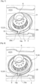
Fig. 3 ] est une vue en perspective du système d'injection, - [
Fig. 4 ] est une vue en perspective du système d'injection, - [
Fig. 5 ] est une vue en perspective du déflecteur, - [
Fig. 6 ] est une vue en perspective d'une partie de la chambre de combustion selon l'invention, le système d'injection étant dans sa seconde position angulaire par rapport au déflecteur, [Fig. 7 ] est une vue en perspective illustrant le fourreau, le fond de chambre et le système d'injection, dans la seconde position angulaire du système d'injection, - [
Fig. 8 ] est une vue correspondant à lafigure 7 , dans laquelle la bague de fermeture a été ajoutée. - Les
figures 2 à 8 illustrent une partie d'une chambre de combustion 1 selon une forme de réalisation de l'invention, destinée à équiper une turbomachine, telle qu'un turboréacteur ou un turbopropulseur d'avion. - La chambre 1 comporte une paroi de révolution interne et une paroi de révolution externe, reliées en amont par une paroi annulaire de fond de chambre 4.
- La paroi de fond de chambre 4 comporte des ouvertures 5 dans lesquelles sont montés des systèmes d'injection 6 d'un mélange d'air et de carburant dans la chambre 1, l'air provenant du diffuseur et le carburant étant amené par des injecteurs (non représentés) régulièrement répartis sur la circonférence de la chambre de combustion 1. Chaque injecteur comprend une tête d'injection de carburant aligné sur l'axe A de l'ouverture 5 correspondante.
- Une partie du débit d'air fourni par le compresseur et sortant du diffuseur alimente des conduits annulaires interne et externe de contournement de la chambre de combustion. L'autre partie du débit d'air pénètre dans les système d'injection et est ensuite mélangée au carburant amené par les injecteurs avant d'être pulvérisée dans la chambre de combustion 1.
- Pour chaque système d'injection 6, un injecteur de carburant central est entouré par une paroi annulaire 7 dudit système d'injection 6 formant un venturi. Un bol 8 entoure la paroi annulaire, ledit bol 8 s'évasant vers l'aval.
- L'extrémité aval du bol 8 comporte un rebord annulaire 17 s'étendant radialement vers l'extérieur. Comme cela est mieux visible aux
figures 3 et 4 , des ergots ou des pattes 18 s'étendent radialement vers l'extérieur depuis la périphérie radialement externe du rebord annulaire 17. Les ergots sont ici au nombre de trois et sont régulièrement répartis sur la circonférence, c'est-à-dire sont décalés angulairement les uns par rapport aux autre d'un angle de 120°. - Le système d'injection 6 comporte en outre classiquement des ailettes 9 destinées à imprimer au flux d'air entrant par le canal délimité entre le bol 8 et la paroi annulaire un mouvement de giration favorisant l'homogénéisation du mélange d'air et de carburant.
- La périphérie radialement externe du bol comporte un rebord radial 10 relié au rebord 17 par une partie cylindrique 19. Le rebord 10 est situé axialement en amont du rebord 17. Le rebord 10 est monté de façon mobile dans une gorge radiale 11 délimitée par un fourreau 12 soudé sur la paroi de fond 4 de la chambre de combustion 1 et par une bague de fermeture 13 soudée au fourreau 12. Le rebord 10 comporte une patte 10a s'étendant radialement vers l'extérieur depuis l'extrémité radialement externe du rebord 10.
- Le déplacement radial du rebord 10 dans la gorge 11 permet de compenser les déplacements relatifs entre les injecteurs et le carter de la turbomachine sur lequel ils sont fixés, d'une part, et la chambre de combustion 1, d'autre part. De tels déplacements apparaissent en fonctionnement en raison des dilatations différentielles entre les divers éléments de la turbomachine,
- Plus particulièrement, le fourreau 12 comporte, d'amont en aval, une partie cylindrique 20, une partie annulaire s'étendant radialement 21 et une partie cylindrique 16. La partie cylindrique 20 présente une diamètre plus importante que la partie cylindrique 16. La partie cylindrique 16 est montée dans l'ouverture 5 de la paroi de fond et est fixée à ladite paroi de fond 4 par soudage ou brasage. La zone radialement interne de la partie radiale 21 comporte une surface d'appui aval venant en appui sur la paroi de fond 4.
- La partie cylindrique 20 s'étend sur une partie seulement de la circonférence. En particulier, le fourreau comporte un secteur angulaire dépourvu de partie cylindrique 20, comme cela est mieux visible à la
figure 7 , ce secteur angulaire s'étend ici sur 120°. Les extrémités circonférentielles 20a, 20b de la partie cylindrique 20 sont aptes à former des butées pour la patte 10a qui est logée dans ledit secteur angulaire dépourvu de partie cylindrique 20. - La bague de fermeture 13 présente une section générale en T, comportant une partie radiale 22 et une partie cylindrique 23 annulaires. L'extrémité aval de la partie cylindrique 23 vient en appui sur la partie radiale 21 du fourreau 12. Ladite partie radiale 21 du fourreau 12 et la partie radiale 22 de la bague de fermeture 23 sont ainsi écartées axialement l'une de l'autre et délimitent entre elle la gorge 11.
- L'extrémité aval de la partie cylindrique 23 comporte une encoche 23a (
figure 8 ) dont la fonction est expliquée après. - Un déflecteur 14 est par ailleurs monté en aval de la paroi de fond 4.
- Le déflecteur 14 comporte, d'amont vers l'aval, une partie cylindrique 15, une partie radiale 24 présentant une forme de secteur d'anneau, et des rebords 25 s'étendant axialement vers l'aval au niveau des bords radialement interne et externe de la partie radiale 24. La partie cylindrique 15 est montée à l'intérieur de la partie cylindrique 16 du fourreau 12 et fixée par brasage ou soudage à ladite partie cylindrique 16.
- La partie cylindrique 16 comporte en outre des rainures 26, ici au nombre de trois, régulièrement réparties sur la circonférence.
- Le montage d'une telle chambre de combustion est réalisé de la manière suivante.
- Le fourreau 12, en particulier la partie cylindrique 16, est tout d'abord monté dans l'ouverture 5 de la paroi de fond 4. Le déflecteur 14, en particulier la partie cylindrique 15, est montée dans la partie cylindrique 16 du fourreau. La partie cylindrique 16, la partie cylindrique 15 et la paroi de fond sont alors assemblées les unes aux autres par soudage ou brasage.
- Le système d'injection est ensuite monté dans l'ouverture 5 de la paroi de fond, au travers du fourreau 12 et du déflecteur 14. En particulier, le système d'injection est positionné dans une première position angulaire de façon à ce que les ergots 18 du système d'injection 6 soit situés en regard des rainures 26 du déflecteur 14. Le système d'injection est ensuite déplacé en translation vers l'aval, jusqu'à ce que le rebord 10 soit en appui sur la partie radiale 21 du fourreau. Les ergots 18 sont alors situés juste en aval de la partie radiale 24 du déflecteur et la patte 10a est logée dans la zone du fourreau 12 dépourvue de rebord cylindrique 20.
- Le système d'injection 16 est ensuite pivoté dans une seconde position angulaire, illustrée aux
figures 6 à 8 . En particulier le système d'injection est pivoté d'un angle de 60° entre les première et seconde positions angulaires, cet angle correspondant à la moitié de l'écartement angulaire entre deux rainures 26 ou entre deux ergots 18. - Dans la seconde position angulaire, la patte 10a du système d'injection 6 vient en appui sur la butée circonférentielle 20a, de façon à faciliter le montage.
- Dans la seconde position angulaire, les ergots 18 sont décalés des rainures 26 et sont aptes à venir en appui sur la partie radiale 24 du déflecteur 14, de façon à empêcher le déplacement axial du système d'injection 6.
- La bague de fermeture 13 est montée dans la partie cylindrique 20 du fourreau 10, de façon à ce que la patte 10a soit logée et maintenue en position dans l'encoche 23a. La bague de fermeture 13 est ensuite fixée par soudage ou brasage au fourreau 12. Le système d'injection 6 est ainsi immobilisé en rotation.
- Une telle structure permet d'assurer un montage simple de l'ensemble tout en empêchant le retrait du déflecteur 14 en cas de débrasage ou dessoudage de la partie cylindrique 15. On évite ainsi une dégradation des parties de la turbomachine qui sont situées en aval de la paroi de fond 4 ou de la chambre de combustion 1.
Claims (10)
- Chambre de combustion (1) de turbomachine, comportant- une paroi de fond (4) comportant au moins une ouverture (5),- au moins un fourreau (12) monté en amont de la paroi de fond (4) et fixé à la paroi de fond (4),- une bague de fermeture (13) délimitant une gorge annulaire (11) avec le fourreau (12) et fixée au fourreau (12),- au moins un système (6) d'injection d'air et de carburant, présentant un axe (A), monté dans l'ouverture (5) de la paroi de fond (4), le système d'injection (6) comprenant un rebord annulaire (10) s'étendant radialement par rapport audit axe (A), monté dans ladite gorge (11) avec un jeu radial,- un déflecteur (14) situé en aval de la paroi de fond (4), fixé au fourreau (12) et/ou à la paroi de fond (4), comportant une partie radialement interne située axialement entre la paroi de fond (4) et une extrémité aval du système d'injection (6), le système d'injection (6) comportant au moins une partie en saillie (18) s'étendant radialement apte à être introduite dans une partie en creux (16) du déflecteur (14), ou inversement le déflecteur (14) comporte au moins une partie en saillie (18) s'étendant radialement apte à être introduite dans une partie en creux (16) du système d'injection (6), dans une première position angulaire de montage du système d'injection (6) par rapport au déflecteur (14), ladite partie en saillie (18) étant apte à venir axialement en butée sur une face radiale du déflecteur (14), ou respectivement du système d'injection (6), dans une seconde position angulaire de maintien du système d'injection (6) par rapport au déflecteur (14), ladite partie en saillie (18) étant décalée angulairement de la partie en creux (16) dans ladite seconde position.
- Chambre de combustion (1) selon la revendication 1, caractérisé en ce qu'elle comporte des moyens de maintien en position (10a, 23a) aptes à maintenir le système d'injection (6) dans sa seconde position par rapport au déflecteur (14).
- Chambre de combustion (1) selon la revendication 1, caractérisée en ce que la partie en saillie (18) s'étend radialement depuis l'extrémité aval du système d'injection (6), la partie en creux (16) étant formée dans le déflecteur (14).
- Chambre de combustion (1) selon la revendication 1 ou 2, caractérisée en ce que le système d'injection (6) comporte une patte (10a) de blocage en rotation immobilisée en rotation par des butées circonférentielles (20a, 23a) du fourreau (12) et/ou de la bague de fermeture (13).
- Chambre de combustion (1) selon la revendication 4, caractérisée en ce que le fourreau (12) comporte une première butée circonférentielle (20b) et une deuxième butée circonférentielle (20a), la patte de blocage en rotation (10a) étant apte à venir en appui sur la première butée circonférentielle (20b) dans la première position angulaire du système d'injection (6), la patte de blocage en rotation (10a) étant apte à venir en appui sur la deuxième butée circonférentielle (20a) dans la seconde position angulaire du système d'injection (6).
- Chambre de combustion (1) selon la revendication 5, caractérisée en ce que la bague de fermeture (13) comporte une troisième butée circonférentielle (23a), la patte (10a) étant apte à être maintenue en position entre les deuxième et troisième butées circonférentielles (20a, 23a), de façon à maintenir le système d'injection (6) dans sa seconde position angulaire.
- Chambre de combustion (1) selon l'une des revendications 1 à 5, caractérisée en ce que le fourreau (12) comporte une partie cylindrique radialement interne (16), montée dans l'ouverture (5) de la paroi de fond (4) et fixée à la périphérie de ladite ouverture (5).
- Chambre de combustion (1) selon la revendication 6, caractérisée en ce que le déflecteur (14) comporte une partie cylindrique (15) montée dans la partie cylindrique radialement interne (16) du fourreau (12) et fixée à ladite partie cylindrique radialement interne (16).
- Chambre de combustion (1) selon l'une des revendications 1 à 7, caractérisée en ce que le fourreau (12) comporte une partie cylindrique radialement externe (20), située axialement en amont de la partie cylindrique radialement interne (16), la bague de fermeture (13) étant montée radialement à l'intérieur de la partie cylindrique radialement externe (20).
- Procédé de montage d'une chambre de combustion (1) selon l'une des revendications 1 à 9, caractérisé en ce qu'il comporte les étapes consistant à :- fixer le fourreau (12) et le déflecteur (14) sur la paroi de fond (4),- positionner le système d'injection (6) dans la première position angulaire et introduire le système d'injection (6) dans l'ouverture de la paroi de fond (4), au travers du fourreau (12) et du déflecteur (14), par translation suivant l'axe (A) du système d'injection (6) et de ladite ouverture (5), la partie en saillie (18) traversant la partie en creux (26)- faire pivoter le système d'injection (6) dans sa seconde position angulaire de façon à ce que la partie en saillie (18) soit apte à former une butée axiale avec le déflecteur (14),- monter la bague de fermeture (13) de façon à maintenir axialement le rebord annulaire (10) du système d'injection (6) dans la gorge (11) délimitée par la bague de fermeture (13) et le fourreau (12) et immobiliser en rotation le système d'injection (6).
Applications Claiming Priority (2)
| Application Number | Priority Date | Filing Date | Title |
|---|---|---|---|
| FR1901635A FR3084731B1 (fr) | 2019-02-19 | 2019-02-19 | Chambre de combustion pour une turbomachine |
| PCT/FR2020/000037 WO2020169894A1 (fr) | 2019-02-19 | 2020-02-19 | Chambre de combustion pour une turbomachine |
Publications (2)
| Publication Number | Publication Date |
|---|---|
| EP3928034A1 EP3928034A1 (fr) | 2021-12-29 |
| EP3928034B1 true EP3928034B1 (fr) | 2023-06-28 |
Family
ID=67185315
Family Applications (1)
| Application Number | Title | Priority Date | Filing Date |
|---|---|---|---|
| EP20721283.8A Active EP3928034B1 (fr) | 2019-02-19 | 2020-02-19 | Chambre de combustion pour une turbomachine |
Country Status (6)
| Country | Link |
|---|---|
| US (1) | US11808456B2 (fr) |
| EP (1) | EP3928034B1 (fr) |
| CN (1) | CN113454391B (fr) |
| CA (1) | CA3129695A1 (fr) |
| FR (1) | FR3084731B1 (fr) |
| WO (1) | WO2020169894A1 (fr) |
Families Citing this family (1)
| Publication number | Priority date | Publication date | Assignee | Title |
|---|---|---|---|---|
| FR3108162B1 (fr) * | 2020-03-10 | 2023-01-13 | Safran Aircraft Engines | Système d’injection pour une chambre annulaire de combustion de turbomachine |
Family Cites Families (33)
| Publication number | Priority date | Publication date | Assignee | Title |
|---|---|---|---|---|
| US3742704A (en) * | 1971-07-13 | 1973-07-03 | Westinghouse Electric Corp | Combustion chamber support structure |
| JPS58138927A (ja) * | 1982-02-15 | 1983-08-18 | Nissan Motor Co Ltd | 燃焼器の支持装置 |
| DE19515537A1 (de) * | 1995-04-27 | 1996-10-31 | Bmw Rolls Royce Gmbh | Kopfteil einer Gasturbinen-Ringbrennkammer |
| US6415610B1 (en) * | 2000-08-18 | 2002-07-09 | Siemens Westinghouse Power Corporation | Apparatus and method for replacement of combustor basket swirlers |
| FR2825785B1 (fr) * | 2001-06-06 | 2004-08-27 | Snecma Moteurs | Liaison de chambre de combustion cmc de turbomachine en deux parties |
| US7310952B2 (en) * | 2003-10-17 | 2007-12-25 | General Electric Company | Methods and apparatus for attaching swirlers to gas turbine engine combustors |
| US7690207B2 (en) * | 2004-08-24 | 2010-04-06 | Pratt & Whitney Canada Corp. | Gas turbine floating collar arrangement |
| FR2886714B1 (fr) * | 2005-06-07 | 2007-09-07 | Snecma Moteurs Sa | Systeme d'injection anti-rotatif pour turbo-reacteur |
| US20070144180A1 (en) * | 2005-12-22 | 2007-06-28 | Honeywell International, Inc. | Dual bayonet engagement and method of assembling a combustor liner in a gas turbine engine |
| FR2897922B1 (fr) * | 2006-02-27 | 2008-10-10 | Snecma Sa | Agencement pour une chambre de combustion de turboreacteur |
| FR2903171B1 (fr) * | 2006-06-29 | 2008-10-17 | Snecma Sa | Agencement a liaison par crabot pour chambre de combustion de turbomachine |
| FR2921464B1 (fr) * | 2007-09-24 | 2014-03-28 | Snecma | Agencement de systemes d'injection dans un fond de chambre de combustion d'un moteur d'aeronef |
| JP4475324B2 (ja) * | 2007-12-21 | 2010-06-09 | 株式会社デンソー | 燃料噴射ポンプ |
| JP4885118B2 (ja) * | 2007-12-21 | 2012-02-29 | 三菱重工業株式会社 | 可変ノズル機構を備えた可変容量型排気ターボ過給機 |
| FR2932251B1 (fr) * | 2008-06-10 | 2011-09-16 | Snecma | Chambre de combustion de moteur a turbine a gaz comportant des deflecteurs en cmc |
| GB0920371D0 (en) * | 2009-11-23 | 2010-01-06 | Rolls Royce Plc | Combustor system |
| US8607577B2 (en) * | 2009-11-24 | 2013-12-17 | United Technologies Corporation | Attaching ceramic matrix composite to high temperature gas turbine structure |
| FR2986856B1 (fr) * | 2012-02-15 | 2018-05-04 | Safran Aircraft Engines | Dispositif d'injection d'air et de carburant pour une chambre de combustion d'une turbomachine |
| CN108953025B (zh) * | 2013-10-01 | 2021-01-15 | 恩普乐斯股份有限公司 | 燃料喷射装置用喷嘴板的安装构造 |
| FR3015640B1 (fr) * | 2013-12-20 | 2015-12-25 | Snecma | Chambre annulaire de combustion dans une turbomachine |
| DE102014215034A1 (de) * | 2014-07-31 | 2016-02-04 | Siemens Aktiengesellschaft | Abdeckkappe für eine Durchgriffsbohrung in einem Hitzeschild und ein in der Durchgriffsbohrung positionierbares Fixierelement sowie Hitzeschild mit einer Abdeckkappe |
| FR3029980B1 (fr) * | 2014-12-15 | 2017-01-13 | Snecma | Systeme de reparation d'une attache equipant une paroi de reacteur |
| CN204351443U (zh) | 2015-01-12 | 2015-05-27 | 中山市西区青原贸易代理服务部 | 儿童椅 |
| FR3031799B1 (fr) * | 2015-01-19 | 2017-02-17 | Snecma | Dispositif d'etancheite ameliore entre un systeme d'injection et un nez d'injecteur de carburant de turbomachine d'aeronef |
| US10041679B2 (en) * | 2015-06-24 | 2018-08-07 | Delavan Inc | Combustion systems |
| FR3042588B1 (fr) * | 2015-10-16 | 2017-11-10 | Snecma | Dispositif d'injection pour une chambre de combustion d'une turbomachine |
| US10429073B2 (en) * | 2015-12-21 | 2019-10-01 | General Electric Company | Combustor cap module and retention system therefor |
| US10539328B2 (en) * | 2016-07-27 | 2020-01-21 | Honda Motor Co., Ltd. | Structure for supporting nozzle guide of gas turbine engine |
| US10876477B2 (en) * | 2016-09-16 | 2020-12-29 | Delavan Inc | Nozzles with internal manifolding |
| US10690347B2 (en) * | 2017-02-01 | 2020-06-23 | General Electric Company | CMC combustor deflector |
| KR102095034B1 (ko) * | 2018-02-09 | 2020-03-30 | 두산중공업 주식회사 | 연소기 및 이를 포함하는 가스터빈 |
| US11035296B2 (en) * | 2018-07-10 | 2021-06-15 | Delavan Inc. | Internal manifold for multipoint injection |
| FR3091574B1 (fr) * | 2019-01-08 | 2020-12-11 | Safran Aircraft Engines | Systeme d’injection pour turbomachine, comprenant une vrille et des trous tourbillonnaires de bol melangeur |
-
2019
- 2019-02-19 FR FR1901635A patent/FR3084731B1/fr active Active
-
2020
- 2020-02-19 WO PCT/FR2020/000037 patent/WO2020169894A1/fr not_active Ceased
- 2020-02-19 EP EP20721283.8A patent/EP3928034B1/fr active Active
- 2020-02-19 CN CN202080014221.8A patent/CN113454391B/zh active Active
- 2020-02-19 US US17/431,254 patent/US11808456B2/en active Active
- 2020-02-19 CA CA3129695A patent/CA3129695A1/fr active Pending
Also Published As
| Publication number | Publication date |
|---|---|
| FR3084731B1 (fr) | 2020-07-03 |
| US11808456B2 (en) | 2023-11-07 |
| WO2020169894A1 (fr) | 2020-08-27 |
| FR3084731A1 (fr) | 2020-02-07 |
| CN113454391A (zh) | 2021-09-28 |
| US20220018543A1 (en) | 2022-01-20 |
| EP3928034A1 (fr) | 2021-12-29 |
| CN113454391B (zh) | 2023-10-03 |
| CA3129695A1 (fr) | 2020-08-27 |
Similar Documents
| Publication | Publication Date | Title |
|---|---|---|
| EP1862644B1 (fr) | Dispositif de guidage d'un flux d'air pour turbomachine, et turbomachine et diffuseur associés | |
| EP2071242B1 (fr) | Système d'injection d'un mélange d'air et de carburant dans une chambre de combustion de turbomachine | |
| EP3569929B1 (fr) | Ensemble pour une chambre de combustion de turbomachine | |
| FR2935777A1 (fr) | Chambre de combustion de turbomachine | |
| EP3201531B1 (fr) | Chambre de combustion de turbomachine | |
| EP3371445B1 (fr) | Tube de dégazage et cône d'éjection pour une turbomachine, ainsi que leur outillage de montage | |
| EP3784958B1 (fr) | Système d'injection pour une chambre annulaire de combustion de turbomachine | |
| EP3928034B1 (fr) | Chambre de combustion pour une turbomachine | |
| FR3099801A1 (fr) | Ensemble pour une turbine de turbomachine | |
| EP3710679B1 (fr) | Dispositif de maintien d'un organe de prelevement d'air radial centripete | |
| EP3824221A1 (fr) | Ensemble pour une turbomachine | |
| EP4179256B1 (fr) | Chambre annulaire de combustion pour une turbomachine d'aéronef | |
| WO2022096825A1 (fr) | Fixation d'un cône d'éjection au carter d'échappement d'une turbomachine | |
| FR2952704A1 (fr) | Guidage rotulant d'une bougie d'allumage dans une chambre de combustion d'une turbomachine | |
| EP3969814B1 (fr) | Turbomachine â gaz avec fixation de chambre de combustion | |
| EP3568638B1 (fr) | Chambre de combustion pour turbomachine | |
| FR3144858A1 (fr) | Système d’injection de carburant pour turbomachine | |
| FR3107107A1 (fr) | Chambre de combustion pour turbomachine | |
| FR2893389A1 (fr) | Paroi transversale de chambre de combustion munie de trous de multiperforation |
Legal Events
| Date | Code | Title | Description |
|---|---|---|---|
| STAA | Information on the status of an ep patent application or granted ep patent |
Free format text: STATUS: UNKNOWN |
|
| STAA | Information on the status of an ep patent application or granted ep patent |
Free format text: STATUS: THE INTERNATIONAL PUBLICATION HAS BEEN MADE |
|
| PUAI | Public reference made under article 153(3) epc to a published international application that has entered the european phase |
Free format text: ORIGINAL CODE: 0009012 |
|
| STAA | Information on the status of an ep patent application or granted ep patent |
Free format text: STATUS: REQUEST FOR EXAMINATION WAS MADE |
|
| 17P | Request for examination filed |
Effective date: 20210824 |
|
| AK | Designated contracting states |
Kind code of ref document: A1 Designated state(s): AL AT BE BG CH CY CZ DE DK EE ES FI FR GB GR HR HU IE IS IT LI LT LU LV MC MK MT NL NO PL PT RO RS SE SI SK SM TR |
|
| DAV | Request for validation of the european patent (deleted) | ||
| DAX | Request for extension of the european patent (deleted) | ||
| STAA | Information on the status of an ep patent application or granted ep patent |
Free format text: STATUS: EXAMINATION IS IN PROGRESS |
|
| 17Q | First examination report despatched |
Effective date: 20220804 |
|
| GRAP | Despatch of communication of intention to grant a patent |
Free format text: ORIGINAL CODE: EPIDOSNIGR1 |
|
| STAA | Information on the status of an ep patent application or granted ep patent |
Free format text: STATUS: GRANT OF PATENT IS INTENDED |
|
| INTG | Intention to grant announced |
Effective date: 20230124 |
|
| RIN1 | Information on inventor provided before grant (corrected) |
Inventor name: VILLENAVE, BENJAMIN, FRANTZ, KARL Inventor name: DOUSSE, WILLIAM,LOUIS, RODOLPHE Inventor name: BUNEL, JACQUES, MARCEL, ARTHUR |
|
| GRAS | Grant fee paid |
Free format text: ORIGINAL CODE: EPIDOSNIGR3 |
|
| GRAA | (expected) grant |
Free format text: ORIGINAL CODE: 0009210 |
|
| STAA | Information on the status of an ep patent application or granted ep patent |
Free format text: STATUS: THE PATENT HAS BEEN GRANTED |
|
| AK | Designated contracting states |
Kind code of ref document: B1 Designated state(s): AL AT BE BG CH CY CZ DE DK EE ES FI FR GB GR HR HU IE IS IT LI LT LU LV MC MK MT NL NO PL PT RO RS SE SI SK SM TR |
|
| REG | Reference to a national code |
Ref country code: CH Ref legal event code: EP |
|
| REG | Reference to a national code |
Ref country code: AT Ref legal event code: REF Ref document number: 1582985 Country of ref document: AT Kind code of ref document: T Effective date: 20230715 |
|
| REG | Reference to a national code |
Ref country code: IE Ref legal event code: FG4D Free format text: LANGUAGE OF EP DOCUMENT: FRENCH |
|
| REG | Reference to a national code |
Ref country code: DE Ref legal event code: R096 Ref document number: 602020013023 Country of ref document: DE |
|
| REG | Reference to a national code |
Ref country code: LT Ref legal event code: MG9D |
|
| PG25 | Lapsed in a contracting state [announced via postgrant information from national office to epo] |
Ref country code: SE Free format text: LAPSE BECAUSE OF FAILURE TO SUBMIT A TRANSLATION OF THE DESCRIPTION OR TO PAY THE FEE WITHIN THE PRESCRIBED TIME-LIMIT Effective date: 20230628 Ref country code: NO Free format text: LAPSE BECAUSE OF FAILURE TO SUBMIT A TRANSLATION OF THE DESCRIPTION OR TO PAY THE FEE WITHIN THE PRESCRIBED TIME-LIMIT Effective date: 20230928 |
|
| REG | Reference to a national code |
Ref country code: NL Ref legal event code: MP Effective date: 20230628 |
|
| REG | Reference to a national code |
Ref country code: AT Ref legal event code: MK05 Ref document number: 1582985 Country of ref document: AT Kind code of ref document: T Effective date: 20230628 |
|
| PG25 | Lapsed in a contracting state [announced via postgrant information from national office to epo] |
Ref country code: RS Free format text: LAPSE BECAUSE OF FAILURE TO SUBMIT A TRANSLATION OF THE DESCRIPTION OR TO PAY THE FEE WITHIN THE PRESCRIBED TIME-LIMIT Effective date: 20230628 Ref country code: NL Free format text: LAPSE BECAUSE OF FAILURE TO SUBMIT A TRANSLATION OF THE DESCRIPTION OR TO PAY THE FEE WITHIN THE PRESCRIBED TIME-LIMIT Effective date: 20230628 Ref country code: LV Free format text: LAPSE BECAUSE OF FAILURE TO SUBMIT A TRANSLATION OF THE DESCRIPTION OR TO PAY THE FEE WITHIN THE PRESCRIBED TIME-LIMIT Effective date: 20230628 Ref country code: LT Free format text: LAPSE BECAUSE OF FAILURE TO SUBMIT A TRANSLATION OF THE DESCRIPTION OR TO PAY THE FEE WITHIN THE PRESCRIBED TIME-LIMIT Effective date: 20230628 Ref country code: HR Free format text: LAPSE BECAUSE OF FAILURE TO SUBMIT A TRANSLATION OF THE DESCRIPTION OR TO PAY THE FEE WITHIN THE PRESCRIBED TIME-LIMIT Effective date: 20230628 Ref country code: GR Free format text: LAPSE BECAUSE OF FAILURE TO SUBMIT A TRANSLATION OF THE DESCRIPTION OR TO PAY THE FEE WITHIN THE PRESCRIBED TIME-LIMIT Effective date: 20230929 |
|
| PG25 | Lapsed in a contracting state [announced via postgrant information from national office to epo] |
Ref country code: FI Free format text: LAPSE BECAUSE OF FAILURE TO SUBMIT A TRANSLATION OF THE DESCRIPTION OR TO PAY THE FEE WITHIN THE PRESCRIBED TIME-LIMIT Effective date: 20230628 |
|
| PG25 | Lapsed in a contracting state [announced via postgrant information from national office to epo] |
Ref country code: SK Free format text: LAPSE BECAUSE OF FAILURE TO SUBMIT A TRANSLATION OF THE DESCRIPTION OR TO PAY THE FEE WITHIN THE PRESCRIBED TIME-LIMIT Effective date: 20230628 |
|
| PG25 | Lapsed in a contracting state [announced via postgrant information from national office to epo] |
Ref country code: ES Free format text: LAPSE BECAUSE OF FAILURE TO SUBMIT A TRANSLATION OF THE DESCRIPTION OR TO PAY THE FEE WITHIN THE PRESCRIBED TIME-LIMIT Effective date: 20230628 |
|
| PG25 | Lapsed in a contracting state [announced via postgrant information from national office to epo] |
Ref country code: IS Free format text: LAPSE BECAUSE OF FAILURE TO SUBMIT A TRANSLATION OF THE DESCRIPTION OR TO PAY THE FEE WITHIN THE PRESCRIBED TIME-LIMIT Effective date: 20231028 |
|
| PG25 | Lapsed in a contracting state [announced via postgrant information from national office to epo] |
Ref country code: SM Free format text: LAPSE BECAUSE OF FAILURE TO SUBMIT A TRANSLATION OF THE DESCRIPTION OR TO PAY THE FEE WITHIN THE PRESCRIBED TIME-LIMIT Effective date: 20230628 Ref country code: SK Free format text: LAPSE BECAUSE OF FAILURE TO SUBMIT A TRANSLATION OF THE DESCRIPTION OR TO PAY THE FEE WITHIN THE PRESCRIBED TIME-LIMIT Effective date: 20230628 Ref country code: RO Free format text: LAPSE BECAUSE OF FAILURE TO SUBMIT A TRANSLATION OF THE DESCRIPTION OR TO PAY THE FEE WITHIN THE PRESCRIBED TIME-LIMIT Effective date: 20230628 Ref country code: PT Free format text: LAPSE BECAUSE OF FAILURE TO SUBMIT A TRANSLATION OF THE DESCRIPTION OR TO PAY THE FEE WITHIN THE PRESCRIBED TIME-LIMIT Effective date: 20231030 Ref country code: IS Free format text: LAPSE BECAUSE OF FAILURE TO SUBMIT A TRANSLATION OF THE DESCRIPTION OR TO PAY THE FEE WITHIN THE PRESCRIBED TIME-LIMIT Effective date: 20231028 Ref country code: ES Free format text: LAPSE BECAUSE OF FAILURE TO SUBMIT A TRANSLATION OF THE DESCRIPTION OR TO PAY THE FEE WITHIN THE PRESCRIBED TIME-LIMIT Effective date: 20230628 Ref country code: EE Free format text: LAPSE BECAUSE OF FAILURE TO SUBMIT A TRANSLATION OF THE DESCRIPTION OR TO PAY THE FEE WITHIN THE PRESCRIBED TIME-LIMIT Effective date: 20230628 Ref country code: CZ Free format text: LAPSE BECAUSE OF FAILURE TO SUBMIT A TRANSLATION OF THE DESCRIPTION OR TO PAY THE FEE WITHIN THE PRESCRIBED TIME-LIMIT Effective date: 20230628 Ref country code: AT Free format text: LAPSE BECAUSE OF FAILURE TO SUBMIT A TRANSLATION OF THE DESCRIPTION OR TO PAY THE FEE WITHIN THE PRESCRIBED TIME-LIMIT Effective date: 20230628 |
|
| PG25 | Lapsed in a contracting state [announced via postgrant information from national office to epo] |
Ref country code: PL Free format text: LAPSE BECAUSE OF FAILURE TO SUBMIT A TRANSLATION OF THE DESCRIPTION OR TO PAY THE FEE WITHIN THE PRESCRIBED TIME-LIMIT Effective date: 20230628 |
|
| REG | Reference to a national code |
Ref country code: DE Ref legal event code: R097 Ref document number: 602020013023 Country of ref document: DE |
|
| PG25 | Lapsed in a contracting state [announced via postgrant information from national office to epo] |
Ref country code: DK Free format text: LAPSE BECAUSE OF FAILURE TO SUBMIT A TRANSLATION OF THE DESCRIPTION OR TO PAY THE FEE WITHIN THE PRESCRIBED TIME-LIMIT Effective date: 20230628 |
|
| PLBE | No opposition filed within time limit |
Free format text: ORIGINAL CODE: 0009261 |
|
| STAA | Information on the status of an ep patent application or granted ep patent |
Free format text: STATUS: NO OPPOSITION FILED WITHIN TIME LIMIT |
|
| PG25 | Lapsed in a contracting state [announced via postgrant information from national office to epo] |
Ref country code: IT Free format text: LAPSE BECAUSE OF FAILURE TO SUBMIT A TRANSLATION OF THE DESCRIPTION OR TO PAY THE FEE WITHIN THE PRESCRIBED TIME-LIMIT Effective date: 20230628 |
|
| 26N | No opposition filed |
Effective date: 20240402 |
|
| PG25 | Lapsed in a contracting state [announced via postgrant information from national office to epo] |
Ref country code: SI Free format text: LAPSE BECAUSE OF FAILURE TO SUBMIT A TRANSLATION OF THE DESCRIPTION OR TO PAY THE FEE WITHIN THE PRESCRIBED TIME-LIMIT Effective date: 20230628 |
|
| PG25 | Lapsed in a contracting state [announced via postgrant information from national office to epo] |
Ref country code: MC Free format text: LAPSE BECAUSE OF FAILURE TO SUBMIT A TRANSLATION OF THE DESCRIPTION OR TO PAY THE FEE WITHIN THE PRESCRIBED TIME-LIMIT Effective date: 20230628 |
|
| REG | Reference to a national code |
Ref country code: CH Ref legal event code: PL |
|
| PG25 | Lapsed in a contracting state [announced via postgrant information from national office to epo] |
Ref country code: LU Free format text: LAPSE BECAUSE OF NON-PAYMENT OF DUE FEES Effective date: 20240219 |
|
| PG25 | Lapsed in a contracting state [announced via postgrant information from national office to epo] |
Ref country code: CH Free format text: LAPSE BECAUSE OF NON-PAYMENT OF DUE FEES Effective date: 20240229 |
|
| PG25 | Lapsed in a contracting state [announced via postgrant information from national office to epo] |
Ref country code: LU Free format text: LAPSE BECAUSE OF NON-PAYMENT OF DUE FEES Effective date: 20240219 Ref country code: CH Free format text: LAPSE BECAUSE OF NON-PAYMENT OF DUE FEES Effective date: 20240229 |
|
| PG25 | Lapsed in a contracting state [announced via postgrant information from national office to epo] |
Ref country code: BG Free format text: LAPSE BECAUSE OF FAILURE TO SUBMIT A TRANSLATION OF THE DESCRIPTION OR TO PAY THE FEE WITHIN THE PRESCRIBED TIME-LIMIT Effective date: 20230628 |
|
| PG25 | Lapsed in a contracting state [announced via postgrant information from national office to epo] |
Ref country code: BG Free format text: LAPSE BECAUSE OF FAILURE TO SUBMIT A TRANSLATION OF THE DESCRIPTION OR TO PAY THE FEE WITHIN THE PRESCRIBED TIME-LIMIT Effective date: 20230628 |
|
| REG | Reference to a national code |
Ref country code: BE Ref legal event code: MM Effective date: 20240229 |
|
| PG25 | Lapsed in a contracting state [announced via postgrant information from national office to epo] |
Ref country code: BE Free format text: LAPSE BECAUSE OF NON-PAYMENT OF DUE FEES Effective date: 20240229 |
|
| PG25 | Lapsed in a contracting state [announced via postgrant information from national office to epo] |
Ref country code: IE Free format text: LAPSE BECAUSE OF NON-PAYMENT OF DUE FEES Effective date: 20240219 |
|
| PG25 | Lapsed in a contracting state [announced via postgrant information from national office to epo] |
Ref country code: IE Free format text: LAPSE BECAUSE OF NON-PAYMENT OF DUE FEES Effective date: 20240219 Ref country code: BE Free format text: LAPSE BECAUSE OF NON-PAYMENT OF DUE FEES Effective date: 20240229 |
|
| PG25 | Lapsed in a contracting state [announced via postgrant information from national office to epo] |
Ref country code: CY Free format text: LAPSE BECAUSE OF FAILURE TO SUBMIT A TRANSLATION OF THE DESCRIPTION OR TO PAY THE FEE WITHIN THE PRESCRIBED TIME-LIMIT; INVALID AB INITIO Effective date: 20200219 |
|
| PG25 | Lapsed in a contracting state [announced via postgrant information from national office to epo] |
Ref country code: HU Free format text: LAPSE BECAUSE OF FAILURE TO SUBMIT A TRANSLATION OF THE DESCRIPTION OR TO PAY THE FEE WITHIN THE PRESCRIBED TIME-LIMIT; INVALID AB INITIO Effective date: 20200219 |
|
| PG25 | Lapsed in a contracting state [announced via postgrant information from national office to epo] |
Ref country code: TR Free format text: LAPSE BECAUSE OF FAILURE TO SUBMIT A TRANSLATION OF THE DESCRIPTION OR TO PAY THE FEE WITHIN THE PRESCRIBED TIME-LIMIT Effective date: 20230628 |
|
| PGFP | Annual fee paid to national office [announced via postgrant information from national office to epo] |
Ref country code: GB Payment date: 20260219 Year of fee payment: 7 |
|
| PGFP | Annual fee paid to national office [announced via postgrant information from national office to epo] |
Ref country code: DE Payment date: 20260217 Year of fee payment: 7 |
|
| PGFP | Annual fee paid to national office [announced via postgrant information from national office to epo] |
Ref country code: FR Payment date: 20260219 Year of fee payment: 7 |