EP3928066B1 - Capteur à distance actif multispectral - Google Patents
Capteur à distance actif multispectral Download PDFInfo
- Publication number
- EP3928066B1 EP3928066B1 EP21703393.5A EP21703393A EP3928066B1 EP 3928066 B1 EP3928066 B1 EP 3928066B1 EP 21703393 A EP21703393 A EP 21703393A EP 3928066 B1 EP3928066 B1 EP 3928066B1
- Authority
- EP
- European Patent Office
- Prior art keywords
- radiation
- wavelength
- narrow band
- arrangement according
- optical
- Prior art date
- Legal status (The legal status is an assumption and is not a legal conclusion. Google has not performed a legal analysis and makes no representation as to the accuracy of the status listed.)
- Active
Links
Images




Classifications
-
- G—PHYSICS
- G01—MEASURING; TESTING
- G01J—MEASUREMENT OF INTENSITY, VELOCITY, SPECTRAL CONTENT, POLARISATION, PHASE OR PULSE CHARACTERISTICS OF INFRARED, VISIBLE OR ULTRAVIOLET LIGHT; COLORIMETRY; RADIATION PYROMETRY
- G01J3/00—Spectrometry; Spectrophotometry; Monochromators; Measuring colours
- G01J3/28—Investigating the spectrum
- G01J3/30—Measuring the intensity of spectral lines directly on the spectrum itself
- G01J3/32—Investigating bands of a spectrum in sequence by a single detector
-
- G—PHYSICS
- G01—MEASURING; TESTING
- G01J—MEASUREMENT OF INTENSITY, VELOCITY, SPECTRAL CONTENT, POLARISATION, PHASE OR PULSE CHARACTERISTICS OF INFRARED, VISIBLE OR ULTRAVIOLET LIGHT; COLORIMETRY; RADIATION PYROMETRY
- G01J3/00—Spectrometry; Spectrophotometry; Monochromators; Measuring colours
- G01J3/02—Details
- G01J3/0205—Optical elements not provided otherwise, e.g. optical manifolds, diffusers, windows
- G01J3/0227—Optical elements not provided otherwise, e.g. optical manifolds, diffusers, windows using notch filters
-
- G—PHYSICS
- G01—MEASURING; TESTING
- G01J—MEASUREMENT OF INTENSITY, VELOCITY, SPECTRAL CONTENT, POLARISATION, PHASE OR PULSE CHARACTERISTICS OF INFRARED, VISIBLE OR ULTRAVIOLET LIGHT; COLORIMETRY; RADIATION PYROMETRY
- G01J3/00—Spectrometry; Spectrophotometry; Monochromators; Measuring colours
- G01J3/02—Details
- G01J3/0205—Optical elements not provided otherwise, e.g. optical manifolds, diffusers, windows
- G01J3/0237—Adjustable, e.g. focussing
-
- G—PHYSICS
- G01—MEASURING; TESTING
- G01J—MEASUREMENT OF INTENSITY, VELOCITY, SPECTRAL CONTENT, POLARISATION, PHASE OR PULSE CHARACTERISTICS OF INFRARED, VISIBLE OR ULTRAVIOLET LIGHT; COLORIMETRY; RADIATION PYROMETRY
- G01J3/00—Spectrometry; Spectrophotometry; Monochromators; Measuring colours
- G01J3/28—Investigating the spectrum
-
- G—PHYSICS
- G01—MEASURING; TESTING
- G01J—MEASUREMENT OF INTENSITY, VELOCITY, SPECTRAL CONTENT, POLARISATION, PHASE OR PULSE CHARACTERISTICS OF INFRARED, VISIBLE OR ULTRAVIOLET LIGHT; COLORIMETRY; RADIATION PYROMETRY
- G01J3/00—Spectrometry; Spectrophotometry; Monochromators; Measuring colours
- G01J3/28—Investigating the spectrum
- G01J3/2823—Imaging spectrometer
-
- G—PHYSICS
- G01—MEASURING; TESTING
- G01S—RADIO DIRECTION-FINDING; RADIO NAVIGATION; DETERMINING DISTANCE OR VELOCITY BY USE OF RADIO WAVES; LOCATING OR PRESENCE-DETECTING BY USE OF THE REFLECTION OR RERADIATION OF RADIO WAVES; ANALOGOUS ARRANGEMENTS USING OTHER WAVES
- G01S17/00—Systems using the reflection or reradiation of electromagnetic waves other than radio waves, e.g. lidar systems
- G01S17/88—Lidar systems specially adapted for specific applications
- G01S17/89—Lidar systems specially adapted for specific applications for mapping or imaging
-
- G—PHYSICS
- G01—MEASURING; TESTING
- G01S—RADIO DIRECTION-FINDING; RADIO NAVIGATION; DETERMINING DISTANCE OR VELOCITY BY USE OF RADIO WAVES; LOCATING OR PRESENCE-DETECTING BY USE OF THE REFLECTION OR RERADIATION OF RADIO WAVES; ANALOGOUS ARRANGEMENTS USING OTHER WAVES
- G01S7/00—Details of systems according to groups G01S13/00, G01S15/00, G01S17/00
- G01S7/48—Details of systems according to groups G01S13/00, G01S15/00, G01S17/00 of systems according to group G01S17/00
- G01S7/4802—Details of systems according to groups G01S13/00, G01S15/00, G01S17/00 of systems according to group G01S17/00 using analysis of echo signal for target characterisation; Target signature; Target cross-section
-
- G—PHYSICS
- G01—MEASURING; TESTING
- G01S—RADIO DIRECTION-FINDING; RADIO NAVIGATION; DETERMINING DISTANCE OR VELOCITY BY USE OF RADIO WAVES; LOCATING OR PRESENCE-DETECTING BY USE OF THE REFLECTION OR RERADIATION OF RADIO WAVES; ANALOGOUS ARRANGEMENTS USING OTHER WAVES
- G01S7/00—Details of systems according to groups G01S13/00, G01S15/00, G01S17/00
- G01S7/48—Details of systems according to groups G01S13/00, G01S15/00, G01S17/00 of systems according to group G01S17/00
- G01S7/481—Constructional features, e.g. arrangements of optical elements
- G01S7/4816—Constructional features, e.g. arrangements of optical elements of receivers alone
-
- G—PHYSICS
- G01—MEASURING; TESTING
- G01S—RADIO DIRECTION-FINDING; RADIO NAVIGATION; DETERMINING DISTANCE OR VELOCITY BY USE OF RADIO WAVES; LOCATING OR PRESENCE-DETECTING BY USE OF THE REFLECTION OR RERADIATION OF RADIO WAVES; ANALOGOUS ARRANGEMENTS USING OTHER WAVES
- G01S7/00—Details of systems according to groups G01S13/00, G01S15/00, G01S17/00
- G01S7/48—Details of systems according to groups G01S13/00, G01S15/00, G01S17/00 of systems according to group G01S17/00
- G01S7/481—Constructional features, e.g. arrangements of optical elements
- G01S7/4817—Constructional features, e.g. arrangements of optical elements relating to scanning
-
- G—PHYSICS
- G01—MEASURING; TESTING
- G01J—MEASUREMENT OF INTENSITY, VELOCITY, SPECTRAL CONTENT, POLARISATION, PHASE OR PULSE CHARACTERISTICS OF INFRARED, VISIBLE OR ULTRAVIOLET LIGHT; COLORIMETRY; RADIATION PYROMETRY
- G01J3/00—Spectrometry; Spectrophotometry; Monochromators; Measuring colours
- G01J3/12—Generating the spectrum; Monochromators
- G01J2003/1226—Interference filters
- G01J2003/1247—Tuning
-
- G—PHYSICS
- G01—MEASURING; TESTING
- G01J—MEASUREMENT OF INTENSITY, VELOCITY, SPECTRAL CONTENT, POLARISATION, PHASE OR PULSE CHARACTERISTICS OF INFRARED, VISIBLE OR ULTRAVIOLET LIGHT; COLORIMETRY; RADIATION PYROMETRY
- G01J3/00—Spectrometry; Spectrophotometry; Monochromators; Measuring colours
- G01J3/12—Generating the spectrum; Monochromators
- G01J2003/1269—Electrooptic filter
-
- G—PHYSICS
- G01—MEASURING; TESTING
- G01J—MEASUREMENT OF INTENSITY, VELOCITY, SPECTRAL CONTENT, POLARISATION, PHASE OR PULSE CHARACTERISTICS OF INFRARED, VISIBLE OR ULTRAVIOLET LIGHT; COLORIMETRY; RADIATION PYROMETRY
- G01J3/00—Spectrometry; Spectrophotometry; Monochromators; Measuring colours
- G01J3/28—Investigating the spectrum
- G01J3/2823—Imaging spectrometer
- G01J2003/2826—Multispectral imaging, e.g. filter imaging
Definitions
- the invention relates to multispectral active remote sensing, and more particularly, to multispectral LiDAR devices acquiring data at different wavelengths to allow a recording of a diversity of spectral reflectance from objects.
- Multispectral active remote sensors include one or more illumination sources producing a radiation with multiple wavelengths to illuminate an object, one or more sensors to measure the backscattered radiation and analyze the spectral response of the object. Such systems can be configured to scan multiple points in a 2D or 3D space to generate a frame, an image or a sequence of frames or images. When a large number of wavelengths are analyzed, these multispectral active remote sensors may be referred to as hyperspectral sensors.
- US2019/306386A1 is about an optical filter for a camera which is switchable between a reflection state and a transmission state.
- the optical filter includes a plurality of liquid crystals.
- WO2019/180019A1 is about a scanning device for laser detection and ranging (Li DAR).
- US6101034A is about a tunable multispectral optical apparatus.
- wavelengths are transmitted and received. Detecting the variety of wavelengths is performed either sequentially, with a single receiver, or in parallel, with the number of receivers equal to the number of wavelengths.
- An object of embodiments of the invention is to improve both the spatial information and the spectral information in a multispectral active remote sensing system.
- the target is illuminated with broadband radiations.
- the spectral profile of the illumination radiations is analyzed using inverse narrowband filters.
- a "notch" filter is used to remove a single wavelength band from the broadband spectrum.
- the sequence of measurements is similar to the direct filtering method with the exception that a measurement using the full spectrum is taken which provides the total return energy. Then, measurements are taken sequentially with one spectral band removed from the sequential transmissions each time (e.g., by sequentially adjusting the frequency of the notch filter).
- a distinct advantage to this technique is that nearly all the broadband radiation energy is available for range measurements. For example, in the direct filtering approach with 10 narrow bands, only -1/10 th of the total energy is available for range measurements. In the inverse approach it is -9/10 ths of the energy.
- the disclosure provides a radiation arrangement for a multispectral active remote sensing device, comprising:
- the radiation arrangement may be configured to scan the whole spectral range, in an inverse way, i.e. by successively blocking narrow bands within the whole spectral range.
- a direct filtering refers to scanning the whole spectral range, in an direct way, i.e. by successively transmitting narrow bands within the whole spectral range.
- a reflected part of the radiation beam refers to either backscattered or specular reflection of the transmitted part or combination thereof.
- multispectral active remote sensing devices may comprise an arrangement such as the arrangement hereinabove described.
- the multispectral active remote sensing device may be a radar or a LiDAR.
- the radiation arrangement can be applied to multispectral imaging systems in astronomy, agriculture, autonomous driving, geosciences, geophysics, physics and surveillance such as multispectral LiDAR systems, laser-based telescope (e.g. with a laser guide star).
- multispectral imaging systems in molecular biology, in vivo non-contact imaging and biomedical imaging such as multispectral microscopy systems, imaging spectrometer, imaging spectroscope and diagnostic tools.
- Embodiments can be applied to multispectral systems for purpose of finding objects, identifying materials based on a spectral signature, or detecting processes. Thanks to the inverse way of spectrally scanning, the presence of far field objects may be detected
- spectral active remote sensing systems work for a relatively short range.
- System according to embodiments of the invention can work at a much longer range for detection purposes.
- the spectral signature information may be available beyond a certain range (or will be noisy), but the system will at least be able to detect.
- Such an arrangement may comprise one or more of the following features or combination thereof.
- the wavelength-adjustable narrow band stopper is arranged on a radiation path of the radiation beam from the radiation source to the transceiver.
- the wavelength-adjustable narrow band stopper is arranged on the transmission side of the multispectral active remote sensing.
- the wavelength-adjustable narrow band stopper is arranged on a radiation path of the radiation beam from transceiver to the detector.
- the wavelength-adjustable narrow band stopper is arranged on the receiving side of the multispectral LiDAR.
- the wavelength-adjustable narrow band stopper is further configured to sequentially select a number N of selected wavelength, wherein N is comprised between 4 and 6.
- the multispectral active remote sensing device is a multispectral LiDAR, wherein:
- the technique can be implemented with a multispectral LiDAR comprising a broadband laser source and single receiver. It can be advantageously applied to multispectral LiDAR for far field / long range detection: indeed, the special configuration of the LiDAR makes it possible to detect target located to a larger range compared to the prior art. Indeed, distinct advantage of such a configuration is that nearly all the broadband laser energy is available for range measurements.
- the performances are similar to a multispectral LiDAR comprising a laser source which includes a tunable laser, while retaining the simplicity and low cost of a broadband source.
- the spectral range could be basically anything from the UV to the far IR, for instance as broad as 200 -10000 nm.
- the spectral range could be basically anything from the UV to the far IR, for instance as broad as 200 -10000 nm.
- the spectral range of the laser beam is about 300nm, between 1400nm and 1700 nm.
- the wavelength-adjustable narrow band stopper comprises a filter per selected wavelength, wherein the filter is a notch filter having a narrow band value comprised between 9nm and 20nm, centered on said selected wavelength.
- wavelength-adjustable narrow band stopper comprises a filter per selected wavelength, wherein the filter is selected in the list consisting in:
- Hard Coated OD 4 Bandpass Filters are ideal for eliminating unwanted background noise and enhancing the signal to noise ratio for a range of imaging applications.
- these hard-coated filters are fabricated using only a single substrate.
- Dichroic filters are typically used in reflection that means reflecting unwanted wavelenghts, while transmitting the desired portion of the spectrum. These filters are designed to work at a determined angle of incidence. In such a scenario, specific wavelengths range are reflected while transmitting others.
- the wavelength-adjustable narrow band stopper comprises a wavelength-tunable notch filter configured to block the narrow band centered on a notch wavelength, wherein the notch filter is controlled such as to tune the notch wavelength on the selected wavelength value.
- the wavelength-tunable notch filter is based on liquid crystal modulators.
- the wavelength-adjustable narrow band stopper comprises volume holographic notch filters.
- the transceiver has a spatial scanning function.
- the detector comprises a single radiation power sensor.
- the disclosure also provides a multispectral active remote sensing device comprising an arrangement as described hereinabove, further comprising the radiation source.
- the broadband laser source can be a solid-state laser source for instance.
- the broadband laser source is not limited to a supercontinuum source. It could be any spectrally broadband light such as Raman lasers for instance.
- the disclosure also provides a method for operating: an arrangement as described hereinabove, or the multispectral active remote sensing device comprising the same, the method comprising:
- the disclosure further provides a vehicle comprising an arrangement as described hereinabove.
- Figure 1 represents two schematics of broadband spectra.
- the schematics 10 on the left corresponds to a spectrum in the case where a filtering is performed to only transmit a narrowband part of the spectrum, as traditionally configured for instance in multispectral LiDARs.
- spectral information which are Time-of-flight ToF and optical power
- a spectral filtering is performed, wherein the filtering has a bandwidth corresponding to the narrowband part of the spectrum and is centered on the specific wavelength.
- a measured signal 12 in this case is narrowband, centered on the specific wavelength ⁇ k . Therefore, the total energy measured is low because most of the light is rejected light 13.
- the schematics 11 on the right corresponds to a spectrum in the case where the filtering is performed to only block a narrowband part of the spectrum, centered on the specific wavelength ⁇ k , while transmitting the rest of the broadband spectrum.
- a measured signal 12 in this case is broadband. Therefore, the total energy measured is high because the rejected light 13 in this case is narrowband.
- any kind of narrowband blocker can be used to perform such an inverse filtering.
- a narrowband blocker can for instance being also referred to as a band-stop filter or band-rejection filter, and is a filter that passes most frequencies unaltered, but attenuates those in a specific range to very low levels.
- a notch filter is a band-stop filter with a narrow stopband, i.e. a high Q factor.
- Figure 2 schematically illustrates the spectral transmission of a tunable notch filter that can be used in optical arrangements for multispectral LiDARs, in order to perform the narrowband blocking as described above.
- a tunable filter is a filter wherein certain filter parameters are tunable, either manually or with an electronic control system. Applied to notch filters, the tunable parameters may specifically be:
- the transmission is low on the narrowband part of the spectrum which centered on the specific wavelength ⁇ k .
- the attenuation is high on said narrowband part of the spectrum.
- such a narrowband may be also referred to as stop-band, or as "notch", and the center wavelength of the narrowband may also be referred to as a blocked wavelength.
- a second stop-band centered on a second wavelength ⁇ k+1 is illustrated for clarification.
- the spectral blocking may be shifted from the first wavelength ⁇ k to the second wavelength ⁇ k+1 by operating the tunable notch filter to set the blocked wavelength from the first wavelength ⁇ k to the second wavelength ⁇ k+1 .
- tunable notch filters There are different types of tunable notch filters that can be used for multispectral LiDAR application. For instance, one kind is tunable notch filters based on liquid crystal modulators - kind of optical modulators which are based on liquid crystals.
- Liquid crystals are substances which are liquid but not optically isotropic - which is unusual for liquids. They contain long molecules which have a tendency to get aligned to each other, and that preferential orientation leads to anisotropic optical properties. The orientation of those molecules can be manipulated with an applied electric field: they tend to get aligned in a direction parallel to the field lines.
- the advantage is to make possible the live adjustment of the filtered wavelength on a broad spectral region (typically visible plus infrared, as 300 to 1000 nm range).
- a broad spectral region typically visible plus infrared, as 300 to 1000 nm range.
- Liquid crystal tunable notch filters are available from Kent Optronics: http://www.kentoptronics.com/nptnf.html.
- a first multispectral LiDAR 1 operating according to the principle of inverse filtering and comprising a tunable notch filter as described hereinabove is schematically pictured on Figure 3 .
- the multispectral LiDAR 1 comprises a laser source 2 configured to transmit a broadband laser beam 15 as pictured by the spectrum 7.
- the multispectral LiDAR 1 further comprises an optical transceiver 3 arranged for receiving the broadband laser beam 15 from the laser source 2.
- the optical beam transceiver 3 comprises an optical transmitter for outputting the received broadband laser beam 15. More specifically, the optical beam transceiver 3 comprises a spatial scanning unit for directing the received broadband laser beam 15 onto a target 6 on a selected direction. Then, the laser beam 15 is reflected, or back scattered, by the target 6.
- the optical transceiver 3 further comprises an optical receiver being configured to receive a reflected and/or back scattered part of the laser beam 15 from the target 6. In the following, said reflected and/or back scattered part will be referred to as a return signal 16. As represented by the arrow 8, the optical receiver is configured to transmit all the return signal 16 to a tunable notch filter 5.
- the multispectral LiDAR 1 further comprises the tunable notch filter 5.
- the tunable notch filter 5 is configured to set successively the blocked wavelength to 5 pre-defined values spectrally spaced from each other by 60nm. Therefore, the return signal 16 is successively filtered to remove block bands corresponding to the blocked wavelength.
- the multispectral LiDAR 1 further comprises a broadband optical sensor 4, which is arranged to integrate the optical power of the filtered return signal 9, for each of the successive blocked wavelength.
- the multispectral LiDAR 1 is further configured to synchronize the broadband optical sensor 4 with the laser source 2 in order to detect a TOF.
- the multispectral LiDAR 1 is further configured to compare the integrated optical power of the filtered return signal 9 to an integrated optical power of the unfiltered broadband laser beam 15.
- Such a multispectral LiDAR has several advantages compared to traditional multispectral LiDARs. Namely, thanks to the inverse filtering, the optical power detected being higher, it is possible to detect objects in spatial ranges that were unavailable while keeping the simplicity and cost of a single broadband laser source and a single broadband optical sensor.
- a second multispectral LiDAR which is a variant of the first multispectral LiDAR 1 pictured on Figure 3 , is schematically pictured on Figure 4 .
- a major difference between the first and the second multispectral LiDAR 1 is that the tunable notch filter 5 is arranged on the receiving optical path on the first multispectral LiDAR 1, whereas the tunable notch filter 5 is arranged on the transmitting optical path on the second multispectral LiDAR 1.
- the broadband laser beam 15 emitted from the laser source 2 is filtered by the tunable notch filter 5, and the filtered beam 17 is transmitted by the optical transceiver 3 to the target 6.
- the reflected filtered beam 18 is received by the optical transceiver 3, and transmitted to the broadband optical sensor 4.
- thin film bandpass filters used in reflection can be for instance selected in those available from Edmund Optics: https://www.edmundoptics.com/f/hard-coated-od-4-50nm-bandpass-filters/14321 /.
- Thin bandpass filters are designed to selectively transmit a portion of the spectrum while rejecting other wavelengths.
- Optical bandpass filters are ideal for a variety of applications, such as fluorescence microscopy, spectroscopy, clinical chemistry, or imaging. These filters are typically used in the life science, industrial, or R&D industries. These filters offer narrow rejection bands with great reflection of the designated laser wavelength.
- Hard Coated OD 4 Bandpass Filters are ideal for eliminating unwanted background noise and enhancing the signal to noise ratio for a range of imaging applications. Unlike traditional filters, which require multiple substrates and coatings, these hard-coated filters are fabricated using only a single substrate.
- Dichroic filters are typically used in reflection that means reflecting unwanted wavelengths, while transmitting the desired portion of the spectrum. These filters are designed to work at a determined angle of incidence. In such a scenario, specific wavelengths range are reflected while transmitting others as described in the following picture.
- dichroic filters are extremely angle sensitive. When used for any angle(s) outside of their intended design, dichroic filters cannot meet the transmission and wavelength specifications originally indicated.
- a notch filter also known as a band-stop filter or band-rejection filter.
- These filters reject / attenuate signals in a specific frequency band called the stop band frequency range and pass the signals above and below this band. They can be viewed as an inverse of a bandpass filter.
- a notch filter is a band-stop filter with a narrow stopband, such as in the figure below.
- Optical notch filters enable narrow stopband, that's why they can aid in the measurement of biomass concentration, growth of a culture of microorganisms, and other analytical techniques within the life science industry.
- Optical density plays an important role in determining the strength of a notch filter. Indeed, like other filters, a notch filter can also be designed for various rejection levels, which is typically specified in terms of optical density.
- the optical density is defined by a numerical value that coincides with a % transmission through a given medium. With high optical density, there is almost full blocking on the designated stopband.
- volume holographic notch filters such as for example those available from Kaiser Optical Systems: https://www.kosi.com/na_en/products/holographic-filters/notch-filters/standard-products.php
- a holographic optical element is an optical element (such as a lens, filter, beam splitter, or diffraction grating) that is produced using holographic imaging processes or principles.
- optical element such as a lens, filter, beam splitter, or diffraction grating
- holographic imaging processes or principles There are commonly used in optoelectronics applications.
- holographic notch filters are replacing dielectric filters in certain optical systems that incorporate single line laser sources.
- Holographic notch filters are manufactured by illuminating a dichromated gelatin film with two laser beams forming an interference pattern.
- Dielectric notch filters are made by depositing two components in alternating layers.
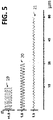
- the refractive index n variation profile over film thickness ( ⁇ m) is different in function of the filter:
- holographic filters are free from extraneous reflection bands and provide significantly higher laser damage thresholds.
- Figures 6 to 10 picture a qualitative analysis in order to explain a simulation method followed to simulate the performance of the inverse filtering applied to multispectral LiDARs.
- spectral channels 22, 23 and 24 defined by perfect rectangular bandpass filters, within a defined spectral range.
- the filters are traditional filters, that is to say, the filters transmit only a defined spectral band while block the rest of the spectral range.
- the respective total energy A1, B1 and C1 of the respective spectral channel 22, 23 and 24 is assumed to be measured at an equal energy value 25, each with a noise incertitude.
- the noise is depicted by a rectangle 27 and represents, for the sake of realism, some measurement uncertainty, which is assumed to be purely statistical. One can therefore depict for each channel an equal noise value 26. Therefore, the noise doesn't depend on the signal intensity, which is realistic for distant targets measurements
- Figure 7 represents the total energy A1, B1 and C1 reflected by the first target, and total energy A2, B2 and C2 reflected by the second target under the same assumptions.
- the difference ⁇ A of energy value in any of the spectral channels needs to be larger than the noise value 26.
- the optical power measured for the first spectral channel is equal to B1+C1, because it transmits all the spectrum but the spectral blocked channel 22. Therefore, the optical power A1 is blocked. Same reasoning is performed for spectral blocked channels 23 and 24.
- Figure 10 pictures the results following the same assumptions for the traditional filters 29 and for the block band filters 30.
- the schematics of the optical powers in the case of the traditional filters 29 are reiterated above the schematics corresponding to the block band filters 30.
- the uncertainty 28 on the difference ⁇ (B+C) on a single spectral channel 22 with a blocking filtering is the same as the uncertainty of the difference ⁇ A on the same single channel 22 with a traditional filtering.
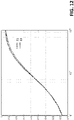
- Figures 11 and 12 picture graphs of results of two simulations, showing the true positive ratio over the signal noise ratio SNR, for the traditional filtering 31, in transmission, and for the notch filtering 32, by blocking a band.
- a spectral angle mapper was used for identifying the spectra. Indeed, a spectral angle mapper is robust, repeatable and fast and enables to compare the performance of filters. The identification rates would get higher with some other classification method.
- TPR true positive ratio
- Spectral identification distance remains similar for bandpass and notch filters, when constant noise is taken into account. Intensity-dependent noise favors bandpass.
- Competing lidars specify measurement distance (e.g. 100 m) and object identification distance (e.g. 60 m). In our case measurement distance and identification distance will also be different.
Landscapes
- Physics & Mathematics (AREA)
- Spectroscopy & Molecular Physics (AREA)
- Engineering & Computer Science (AREA)
- General Physics & Mathematics (AREA)
- Computer Networks & Wireless Communication (AREA)
- Radar, Positioning & Navigation (AREA)
- Remote Sensing (AREA)
- Electromagnetism (AREA)
- Investigating Or Analysing Materials By Optical Means (AREA)
- Measurement Of The Respiration, Hearing Ability, Form, And Blood Characteristics Of Living Organisms (AREA)
Claims (15)
- Agencement de rayonnement pour un dispositif de télédétection active multispectrale, comprenant :un émetteur-récepteur (3) configuré pour recevoir un faisceau de rayonnement en provenance d'une source de rayonnement (2) ; l'émetteur-récepteur (3) étant configuré en outre pour délivrer une partie émise du faisceau de rayonnement sur une cible (6), et configuré en outre pour recevoir une partie réfléchie du faisceau de rayonnement en provenance de la cible (6) ; dans lequel le faisceau de rayonnement présente une plage spectrale à large bande,un détecteur (4) configuré pour détecter un temps de vol et une puissance de rayonnement de la partie réfléchie du faisceau de rayonnement ; etcaractérisé en ce quel'agencement de rayonnement comprend en outre un dispositif d'arrêt à bande étroite réglable en longueur d'onde (5) agencé sur un trajet de rayonnement allant de la source de rayonnement (2) jusqu'au détecteur (4),dans lequelle dispositif d'arrêt à bande étroite réglable en longueur d'onde (5) est configuré pour transmettre le faisceau de rayonnement dans toute la plage spectrale sauf une bande étroite centrée sur une longueur d'onde sélectionnée (λ_k), dans lequel le dispositif d'arrêt à bande étroite réglable en longueur d'onde (5) est configuré en outre pour régler séquentiellement la longueur d'onde sélectionnée (λ_k) sur une autre longueur d'onde (λ_k+1), de la plage spectrale, de sorte que le détecteur (4) reçoit une puissance partielle de rayonnement (11), qui est la puissance de rayonnement de la réflexion reçue du faisceau de rayonnement dans toute la plage spectrale sans la bande étroite centrée sur ladite longueur d'onde sélectionnée,dans lequel le détecteur optique (4) est configuré en outre pour détecter séquentiellement la puissance partielle de rayonnement en association avec la longueur d'onde sélectionnée.
- Agencement de rayonnement selon la revendication 1, dans lequel le dispositif d'arrêt à bande étroite réglable en longueur d'onde (5) est agencé sur un trajet de rayonnement du faisceau de rayonnement allant de la source de rayonnement (2) jusqu'à l'émetteur-récepteur (3).
- Agencement de rayonnement selon la revendication 1, dans lequel le dispositif d'arrêt à bande étroite réglable en longueur d'onde (5) est agencé sur un trajet de rayonnement du faisceau de rayonnement allant de l'émetteur-récepteur (3) jusqu'au détecteur (4).
- Agencement selon l'une des revendications 1 à 3, dans lequel le dispositif d'arrêt à bande étroite réglable en longueur d'onde (5) est configuré en outre pour sélectionner séquentiellement un nombre N de longueurs d'onde sélectionnées, dans lequel N est compris entre 4 et 6.
- Agencement selon l'une des revendications 1 à 4, dans lequel le dispositif de télédétection active multispectrale est un LiDAR multispectral (1), dans lequel :l'agencement de rayonnement est un agencement optique, etla source de rayonnement est une source laser (2), le faisceau de rayonnement étant un faisceau laser,l'émetteur-récepteur est un émetteur-récepteur optique (3),le détecteur étant un détecteur optique (4), la puissance de rayonnement étant une puissance optique, et la puissance partielle de rayonnement étant une puissance optique partielle.
- Agencement selon la revendication 5, dans lequel la plage spectrale du faisceau laser est d'environ 300 nm, entre 1400 nm et 1700 nm.
- Agencement selon la revendication 5 ou 6, en combinaison avec la revendication 2, dans lequel le dispositif d'arrêt à bande étroite réglable en longueur d'onde (5) comprend un filtre par longueur d'onde sélectionnée, dans lequel le filtre est un filtre coupe-bande ayant une valeur de bande étroite comprise entre 9 nm et 20 nm, centrée sur ladite longueur d'onde sélectionnée.
- Agencement selon la revendication 5 ou 6, en combinaison avec la revendication 3, dans lequel le dispositif d'arrêt à bande étroite réglable en longueur d'onde (5) comprend un filtre par longueur d'onde sélectionnée, dans lequel le filtre est sélectionné dans la liste consistant en :- un filtre passe-bande à revêtement dur ayant une valeur de densité optique de 4,0, et une valeur de bande étroite de 45 ou 50 nm centrée sur ladite longueur d'onde sélectionnée, ou- des filtres dichroïques.
- Agencement selon la revendication 5 ou 6, dans lequel le dispositif d'arrêt à bande étroite réglable en longueur d'onde (5) comprend un filtre coupe-bande accordable en longueur d'onde configuré pour bloquer la bande étroite centrée sur une longueur d'onde coupe-bande, dans lequel le filtre coupe-bande est commandé de manière à accorder la longueur d'onde coupe-bande sur la valeur de longueur d'onde sélectionnée.
- Agencement selon la revendication 9, dans lequel le filtre coupe-bande accordable en longueur d'onde est basé sur des modulateurs à cristaux liquides.
- Agencement selon la revendication 5 ou 6, dans lequel le dispositif d'arrêt à bande étroite réglable en longueur d'onde (5) comprend des filtres coupe-bande holographiques en volume.
- Agencement selon l'une des revendications 1 à 11, dans lequel l'émetteur-récepteur présente une fonction de balayage spatial.
- Agencement selon l'une des revendications 1 à 12, dans lequel le détecteur (4) comprend un seul capteur de puissance de rayonnement.
- Dispositif de télédétection active multispectrale comprenant un agencement selon l'une des revendications 1 à 13, comprenant en outre la source de rayonnement (2).
- Procédé pour faire fonctionner : un agencement selon l'une des revendications 1 à 13, ou le dispositif de télédétection active multispectrale selon la revendication 14, le procédé comprenant :- la détection, par le détecteur (4), d'une puissance totale de rayonnement, qui est la puissance optique de la partie réfléchie du faisceau de rayonnement sur toute la plage spectrale, et- la détection, par le détecteur (4), de la puissance partielle de rayonnement associée à une longueur d'onde sélectionnée (λ_k), puisle calcul d'une puissance de rayonnement de bande associée à ladite longueur d'onde sélectionnée (λ_k), par comparaison de la puissance totale de rayonnement et de la puissance partielle de rayonnement.
Applications Claiming Priority (2)
| Application Number | Priority Date | Filing Date | Title |
|---|---|---|---|
| US202062968090P | 2020-01-30 | 2020-01-30 | |
| PCT/EP2021/052273 WO2021152168A1 (fr) | 2020-01-30 | 2021-02-01 | Capteur à distance actif multispectral |
Publications (2)
| Publication Number | Publication Date |
|---|---|
| EP3928066A1 EP3928066A1 (fr) | 2021-12-29 |
| EP3928066B1 true EP3928066B1 (fr) | 2022-11-30 |
Family
ID=74553799
Family Applications (1)
| Application Number | Title | Priority Date | Filing Date |
|---|---|---|---|
| EP21703393.5A Active EP3928066B1 (fr) | 2020-01-30 | 2021-02-01 | Capteur à distance actif multispectral |
Country Status (5)
| Country | Link |
|---|---|
| US (1) | US20230053187A1 (fr) |
| EP (1) | EP3928066B1 (fr) |
| ES (1) | ES2935543T3 (fr) |
| FI (1) | FI3928066T3 (fr) |
| WO (1) | WO2021152168A1 (fr) |
Family Cites Families (15)
| Publication number | Priority date | Publication date | Assignee | Title |
|---|---|---|---|---|
| US6101034A (en) * | 1996-02-09 | 2000-08-08 | Cox; James Allen | Tunable multispectral optical filter and imaging apparatus |
| US7601946B2 (en) * | 2006-09-12 | 2009-10-13 | Ravenbrick, Llc | Electromagnetic sensor incorporating quantum confinement structures |
| US20100110515A1 (en) * | 2007-03-08 | 2010-05-06 | Photon Etc., Inc. | Notch filter system |
| EP2607889A4 (fr) * | 2010-08-18 | 2016-11-09 | Nanoentek Inc | Microscope à fluorescence pour observation d'image à fluorescence multiple, procédé d'observation d'image à fluorescence l'utilisant, et système d'observation d'image à fluorescence multiple |
| US10587938B2 (en) * | 2015-02-27 | 2020-03-10 | University Of Georgia Research Foundation, Inc. | Ultra high-speed photonics based radio frequency switching |
| GB201604995D0 (en) * | 2016-03-24 | 2016-05-11 | Bae Systems Plc | Filter |
| US10761195B2 (en) * | 2016-04-22 | 2020-09-01 | OPSYS Tech Ltd. | Multi-wavelength LIDAR system |
| US10331003B2 (en) * | 2016-09-26 | 2019-06-25 | Heliotrope Technologies, Inc. | Electrochromic privacy window |
| CA3093512A1 (fr) * | 2018-03-19 | 2019-09-26 | Outsight | Procedes et systemes pour identifier une composition de materiau d'objets |
| US10972643B2 (en) * | 2018-03-29 | 2021-04-06 | Microsoft Technology Licensing, Llc | Camera comprising an infrared illuminator and a liquid crystal optical filter switchable between a reflection state and a transmission state for infrared imaging and spectral imaging, and method thereof |
| SG11202111153YA (en) * | 2019-06-07 | 2021-11-29 | Basf Coatings Gmbh | System and method for object recognition under natural and/or artificial light |
| US10802120B1 (en) * | 2019-08-20 | 2020-10-13 | Luminar Technologies, Inc. | Coherent pulsed lidar system |
| US20240201337A1 (en) * | 2019-08-20 | 2024-06-20 | Luminar, Llc | Coherent pulsed lidar system |
| CN112578390A (zh) * | 2019-09-29 | 2021-03-30 | 睿镞科技(北京)有限责任公司 | 激光雷达及生成激光点云数据的方法 |
| US20230057064A1 (en) * | 2020-01-24 | 2023-02-23 | Outsight | A laser detection and ranging (lidar) device |
-
2021
- 2021-02-01 EP EP21703393.5A patent/EP3928066B1/fr active Active
- 2021-02-01 ES ES21703393T patent/ES2935543T3/es active Active
- 2021-02-01 US US17/796,566 patent/US20230053187A1/en active Pending
- 2021-02-01 WO PCT/EP2021/052273 patent/WO2021152168A1/fr not_active Ceased
- 2021-02-01 FI FIEP21703393.5T patent/FI3928066T3/fi active
Also Published As
| Publication number | Publication date |
|---|---|
| ES2935543T3 (es) | 2023-03-07 |
| WO2021152168A1 (fr) | 2021-08-05 |
| EP3928066A1 (fr) | 2021-12-29 |
| FI3928066T3 (fi) | 2023-01-31 |
| US20230053187A1 (en) | 2023-02-16 |
Similar Documents
| Publication | Publication Date | Title |
|---|---|---|
| EP2021748B1 (fr) | Spectromètre et procédé interférométrique | |
| EP0746746B1 (fr) | Analyse multispectrale d'une image | |
| US7599055B2 (en) | Swept wavelength imaging optical interrogation system and method for using same | |
| US7652765B1 (en) | Hyper-spectral imaging methods and devices | |
| CN104040309B (zh) | 用于最终使用者食品分析的低成本光谱测定系统 | |
| US20050270528A1 (en) | Hyper-spectral imaging methods and devices | |
| US8860942B1 (en) | Apparatus for multi-spectral imaging of point event detection | |
| Li et al. | A liquid crystal tunable filter-based hyperspectral LiDAR system and its application on vegetation red edge detection | |
| US7414717B2 (en) | System and method for detection and identification of optical spectra | |
| KR102381930B1 (ko) | 광학 간섭 장치 | |
| EP2414794A1 (fr) | Système et procédé pour la mesure optique d'une cible | |
| US10156523B2 (en) | Optical measuring system based on Raman scattering | |
| WO2005088264A1 (fr) | Procedes et dispositifs d'imagerie hyperspectrale | |
| US10830890B1 (en) | Multispectral LADAR using temporal dispersion | |
| US9476827B2 (en) | System and method of multitechnique imaging for the chemical biological or biochemical analysis of a sample | |
| US20020135770A1 (en) | Hybrid-imaging spectrometer | |
| EP3928066B1 (fr) | Capteur à distance actif multispectral | |
| CN108872703A (zh) | 快速复合制造的高速低噪处理中超频谱无损评估的系统和方法 | |
| EP3404380B1 (fr) | Procédé et dispositif d'étalonnage d'un module de microspectromètre | |
| US20080130001A1 (en) | Hybrid-imaging spectrometer | |
| CN111380816B (zh) | 用于分析目标物的化学成分的方法和系统 | |
| EP3444578B1 (fr) | Procédé et système d'analyse de la composition chimique d'un echantillon | |
| US11698303B2 (en) | Method and system for analysing a chemical composition of a target using a Fabry-Perot interferometer | |
| JP2021071302A (ja) | 物体検査装置および物体検査方法 | |
| WO2026054743A1 (fr) | Procédé de traitement d'image spectroscopique et systèmes de spectromètre à double canal pour analyses médico-légales et de marqueur |
Legal Events
| Date | Code | Title | Description |
|---|---|---|---|
| STAA | Information on the status of an ep patent application or granted ep patent |
Free format text: STATUS: UNKNOWN |
|
| STAA | Information on the status of an ep patent application or granted ep patent |
Free format text: STATUS: THE INTERNATIONAL PUBLICATION HAS BEEN MADE |
|
| PUAI | Public reference made under article 153(3) epc to a published international application that has entered the european phase |
Free format text: ORIGINAL CODE: 0009012 |
|
| STAA | Information on the status of an ep patent application or granted ep patent |
Free format text: STATUS: REQUEST FOR EXAMINATION WAS MADE |
|
| 17P | Request for examination filed |
Effective date: 20210923 |
|
| AK | Designated contracting states |
Kind code of ref document: A1 Designated state(s): AL AT BE BG CH CY CZ DE DK EE ES FI FR GB GR HR HU IE IS IT LI LT LU LV MC MK MT NL NO PL PT RO RS SE SI SK SM TR |
|
| GRAP | Despatch of communication of intention to grant a patent |
Free format text: ORIGINAL CODE: EPIDOSNIGR1 |
|
| STAA | Information on the status of an ep patent application or granted ep patent |
Free format text: STATUS: GRANT OF PATENT IS INTENDED |
|
| DAV | Request for validation of the european patent (deleted) | ||
| DAX | Request for extension of the european patent (deleted) | ||
| INTG | Intention to grant announced |
Effective date: 20220805 |
|
| GRAS | Grant fee paid |
Free format text: ORIGINAL CODE: EPIDOSNIGR3 |
|
| GRAA | (expected) grant |
Free format text: ORIGINAL CODE: 0009210 |
|
| STAA | Information on the status of an ep patent application or granted ep patent |
Free format text: STATUS: THE PATENT HAS BEEN GRANTED |
|
| AK | Designated contracting states |
Kind code of ref document: B1 Designated state(s): AL AT BE BG CH CY CZ DE DK EE ES FI FR GB GR HR HU IE IS IT LI LT LU LV MC MK MT NL NO PL PT RO RS SE SI SK SM TR |
|
| REG | Reference to a national code |
Ref country code: CH Ref legal event code: EP Ref country code: GB Ref legal event code: FG4D |
|
| REG | Reference to a national code |
Ref country code: AT Ref legal event code: REF Ref document number: 1535010 Country of ref document: AT Kind code of ref document: T Effective date: 20221215 Ref country code: DE Ref legal event code: R096 Ref document number: 602021000889 Country of ref document: DE |
|
| REG | Reference to a national code |
Ref country code: IE Ref legal event code: FG4D |
|
| REG | Reference to a national code |
Ref country code: FI Ref legal event code: FGE |
|
| REG | Reference to a national code |
Ref country code: ES Ref legal event code: FG2A Ref document number: 2935543 Country of ref document: ES Kind code of ref document: T3 Effective date: 20230307 |
|
| REG | Reference to a national code |
Ref country code: LT Ref legal event code: MG9D |
|
| REG | Reference to a national code |
Ref country code: NL Ref legal event code: MP Effective date: 20221130 |
|
| PG25 | Lapsed in a contracting state [announced via postgrant information from national office to epo] |
Ref country code: SE Free format text: LAPSE BECAUSE OF FAILURE TO SUBMIT A TRANSLATION OF THE DESCRIPTION OR TO PAY THE FEE WITHIN THE PRESCRIBED TIME-LIMIT Effective date: 20221130 Ref country code: PT Free format text: LAPSE BECAUSE OF FAILURE TO SUBMIT A TRANSLATION OF THE DESCRIPTION OR TO PAY THE FEE WITHIN THE PRESCRIBED TIME-LIMIT Effective date: 20230331 Ref country code: NO Free format text: LAPSE BECAUSE OF FAILURE TO SUBMIT A TRANSLATION OF THE DESCRIPTION OR TO PAY THE FEE WITHIN THE PRESCRIBED TIME-LIMIT Effective date: 20230228 Ref country code: LT Free format text: LAPSE BECAUSE OF FAILURE TO SUBMIT A TRANSLATION OF THE DESCRIPTION OR TO PAY THE FEE WITHIN THE PRESCRIBED TIME-LIMIT Effective date: 20221130 |
|
| REG | Reference to a national code |
Ref country code: AT Ref legal event code: MK05 Ref document number: 1535010 Country of ref document: AT Kind code of ref document: T Effective date: 20221130 |
|
| PG25 | Lapsed in a contracting state [announced via postgrant information from national office to epo] |
Ref country code: RS Free format text: LAPSE BECAUSE OF FAILURE TO SUBMIT A TRANSLATION OF THE DESCRIPTION OR TO PAY THE FEE WITHIN THE PRESCRIBED TIME-LIMIT Effective date: 20221130 Ref country code: PL Free format text: LAPSE BECAUSE OF FAILURE TO SUBMIT A TRANSLATION OF THE DESCRIPTION OR TO PAY THE FEE WITHIN THE PRESCRIBED TIME-LIMIT Effective date: 20221130 Ref country code: LV Free format text: LAPSE BECAUSE OF FAILURE TO SUBMIT A TRANSLATION OF THE DESCRIPTION OR TO PAY THE FEE WITHIN THE PRESCRIBED TIME-LIMIT Effective date: 20221130 Ref country code: IS Free format text: LAPSE BECAUSE OF FAILURE TO SUBMIT A TRANSLATION OF THE DESCRIPTION OR TO PAY THE FEE WITHIN THE PRESCRIBED TIME-LIMIT Effective date: 20230330 Ref country code: HR Free format text: LAPSE BECAUSE OF FAILURE TO SUBMIT A TRANSLATION OF THE DESCRIPTION OR TO PAY THE FEE WITHIN THE PRESCRIBED TIME-LIMIT Effective date: 20221130 Ref country code: GR Free format text: LAPSE BECAUSE OF FAILURE TO SUBMIT A TRANSLATION OF THE DESCRIPTION OR TO PAY THE FEE WITHIN THE PRESCRIBED TIME-LIMIT Effective date: 20230301 |
|
| PG25 | Lapsed in a contracting state [announced via postgrant information from national office to epo] |
Ref country code: NL Free format text: LAPSE BECAUSE OF FAILURE TO SUBMIT A TRANSLATION OF THE DESCRIPTION OR TO PAY THE FEE WITHIN THE PRESCRIBED TIME-LIMIT Effective date: 20221130 |
|
| PG25 | Lapsed in a contracting state [announced via postgrant information from national office to epo] |
Ref country code: SM Free format text: LAPSE BECAUSE OF FAILURE TO SUBMIT A TRANSLATION OF THE DESCRIPTION OR TO PAY THE FEE WITHIN THE PRESCRIBED TIME-LIMIT Effective date: 20221130 Ref country code: RO Free format text: LAPSE BECAUSE OF FAILURE TO SUBMIT A TRANSLATION OF THE DESCRIPTION OR TO PAY THE FEE WITHIN THE PRESCRIBED TIME-LIMIT Effective date: 20221130 Ref country code: EE Free format text: LAPSE BECAUSE OF FAILURE TO SUBMIT A TRANSLATION OF THE DESCRIPTION OR TO PAY THE FEE WITHIN THE PRESCRIBED TIME-LIMIT Effective date: 20221130 Ref country code: DK Free format text: LAPSE BECAUSE OF FAILURE TO SUBMIT A TRANSLATION OF THE DESCRIPTION OR TO PAY THE FEE WITHIN THE PRESCRIBED TIME-LIMIT Effective date: 20221130 Ref country code: CZ Free format text: LAPSE BECAUSE OF FAILURE TO SUBMIT A TRANSLATION OF THE DESCRIPTION OR TO PAY THE FEE WITHIN THE PRESCRIBED TIME-LIMIT Effective date: 20221130 Ref country code: AT Free format text: LAPSE BECAUSE OF FAILURE TO SUBMIT A TRANSLATION OF THE DESCRIPTION OR TO PAY THE FEE WITHIN THE PRESCRIBED TIME-LIMIT Effective date: 20221130 |
|
| PG25 | Lapsed in a contracting state [announced via postgrant information from national office to epo] |
Ref country code: SK Free format text: LAPSE BECAUSE OF FAILURE TO SUBMIT A TRANSLATION OF THE DESCRIPTION OR TO PAY THE FEE WITHIN THE PRESCRIBED TIME-LIMIT Effective date: 20221130 Ref country code: AL Free format text: LAPSE BECAUSE OF FAILURE TO SUBMIT A TRANSLATION OF THE DESCRIPTION OR TO PAY THE FEE WITHIN THE PRESCRIBED TIME-LIMIT Effective date: 20221130 |
|
| REG | Reference to a national code |
Ref country code: DE Ref legal event code: R097 Ref document number: 602021000889 Country of ref document: DE |
|
| PG25 | Lapsed in a contracting state [announced via postgrant information from national office to epo] |
Ref country code: MC Free format text: LAPSE BECAUSE OF FAILURE TO SUBMIT A TRANSLATION OF THE DESCRIPTION OR TO PAY THE FEE WITHIN THE PRESCRIBED TIME-LIMIT Effective date: 20221130 |
|
| PLBE | No opposition filed within time limit |
Free format text: ORIGINAL CODE: 0009261 |
|
| STAA | Information on the status of an ep patent application or granted ep patent |
Free format text: STATUS: NO OPPOSITION FILED WITHIN TIME LIMIT |
|
| REG | Reference to a national code |
Ref country code: GB Ref legal event code: 732E Free format text: REGISTERED BETWEEN 20230914 AND 20230920 |
|
| REG | Reference to a national code |
Ref country code: FI Ref legal event code: PCE Owner name: IRIDESENSE |
|
| REG | Reference to a national code |
Ref country code: BE Ref legal event code: MM Effective date: 20230228 |
|
| REG | Reference to a national code |
Ref country code: DE Ref legal event code: R082 Ref document number: 602021000889 Country of ref document: DE |
|
| RAP2 | Party data changed (patent owner data changed or rights of a patent transferred) |
Owner name: IRIDESENSE |
|
| PG25 | Lapsed in a contracting state [announced via postgrant information from national office to epo] |
Ref country code: LU Free format text: LAPSE BECAUSE OF NON-PAYMENT OF DUE FEES Effective date: 20230201 |
|
| 26N | No opposition filed |
Effective date: 20230831 |
|
| PG25 | Lapsed in a contracting state [announced via postgrant information from national office to epo] |
Ref country code: SI Free format text: LAPSE BECAUSE OF FAILURE TO SUBMIT A TRANSLATION OF THE DESCRIPTION OR TO PAY THE FEE WITHIN THE PRESCRIBED TIME-LIMIT Effective date: 20221130 |
|
| REG | Reference to a national code |
Ref country code: DE Ref legal event code: R081 Ref document number: 602021000889 Country of ref document: DE Owner name: IRIDESENSE, FR Free format text: FORMER OWNER: OUTSIGHT, PARIS, FR |
|
| REG | Reference to a national code |
Ref country code: IE Ref legal event code: MM4A |
|
| PG25 | Lapsed in a contracting state [announced via postgrant information from national office to epo] |
Ref country code: IE Free format text: LAPSE BECAUSE OF NON-PAYMENT OF DUE FEES Effective date: 20230201 |
|
| PG25 | Lapsed in a contracting state [announced via postgrant information from national office to epo] |
Ref country code: BE Free format text: LAPSE BECAUSE OF NON-PAYMENT OF DUE FEES Effective date: 20230228 |
|
| REG | Reference to a national code |
Ref country code: CH Ref legal event code: PL |
|
| PG25 | Lapsed in a contracting state [announced via postgrant information from national office to epo] |
Ref country code: CH Free format text: LAPSE BECAUSE OF NON-PAYMENT OF DUE FEES Effective date: 20240229 |
|
| PG25 | Lapsed in a contracting state [announced via postgrant information from national office to epo] |
Ref country code: CH Free format text: LAPSE BECAUSE OF NON-PAYMENT OF DUE FEES Effective date: 20240229 |
|
| PG25 | Lapsed in a contracting state [announced via postgrant information from national office to epo] |
Ref country code: BG Free format text: LAPSE BECAUSE OF FAILURE TO SUBMIT A TRANSLATION OF THE DESCRIPTION OR TO PAY THE FEE WITHIN THE PRESCRIBED TIME-LIMIT Effective date: 20221130 |
|
| PG25 | Lapsed in a contracting state [announced via postgrant information from national office to epo] |
Ref country code: BG Free format text: LAPSE BECAUSE OF FAILURE TO SUBMIT A TRANSLATION OF THE DESCRIPTION OR TO PAY THE FEE WITHIN THE PRESCRIBED TIME-LIMIT Effective date: 20221130 |
|
| PGFP | Annual fee paid to national office [announced via postgrant information from national office to epo] |
Ref country code: ES Payment date: 20250331 Year of fee payment: 5 |
|
| PG25 | Lapsed in a contracting state [announced via postgrant information from national office to epo] |
Ref country code: CY Free format text: LAPSE BECAUSE OF FAILURE TO SUBMIT A TRANSLATION OF THE DESCRIPTION OR TO PAY THE FEE WITHIN THE PRESCRIBED TIME-LIMIT; INVALID AB INITIO Effective date: 20210201 |
|
| PG25 | Lapsed in a contracting state [announced via postgrant information from national office to epo] |
Ref country code: HU Free format text: LAPSE BECAUSE OF FAILURE TO SUBMIT A TRANSLATION OF THE DESCRIPTION OR TO PAY THE FEE WITHIN THE PRESCRIBED TIME-LIMIT; INVALID AB INITIO Effective date: 20210201 |
|
| PG25 | Lapsed in a contracting state [announced via postgrant information from national office to epo] |
Ref country code: TR Free format text: LAPSE BECAUSE OF FAILURE TO SUBMIT A TRANSLATION OF THE DESCRIPTION OR TO PAY THE FEE WITHIN THE PRESCRIBED TIME-LIMIT Effective date: 20221130 |
|
| PGFP | Annual fee paid to national office [announced via postgrant information from national office to epo] |
Ref country code: GB Payment date: 20260220 Year of fee payment: 6 |
|
| PGFP | Annual fee paid to national office [announced via postgrant information from national office to epo] |
Ref country code: DE Payment date: 20260218 Year of fee payment: 6 |
|
| PGFP | Annual fee paid to national office [announced via postgrant information from national office to epo] |
Ref country code: FI Payment date: 20260226 Year of fee payment: 6 Ref country code: IT Payment date: 20260224 Year of fee payment: 6 |
|
| PGFP | Annual fee paid to national office [announced via postgrant information from national office to epo] |
Ref country code: FR Payment date: 20260219 Year of fee payment: 6 |