EP3929079B1 - Fallschirmvorrichtung, fluggerät und flugkörperausstossmechanismus - Google Patents
Fallschirmvorrichtung, fluggerät und flugkörperausstossmechanismus Download PDFInfo
- Publication number
- EP3929079B1 EP3929079B1 EP19915908.8A EP19915908A EP3929079B1 EP 3929079 B1 EP3929079 B1 EP 3929079B1 EP 19915908 A EP19915908 A EP 19915908A EP 3929079 B1 EP3929079 B1 EP 3929079B1
- Authority
- EP
- European Patent Office
- Prior art keywords
- section
- parachute
- flying body
- ejection
- flying
- Prior art date
- Legal status (The legal status is an assumption and is not a legal conclusion. Google has not performed a legal analysis and makes no representation as to the accuracy of the status listed.)
- Active
Links
Images



Classifications
-
- B—PERFORMING OPERATIONS; TRANSPORTING
- B64—AIRCRAFT; AVIATION; COSMONAUTICS
- B64D—EQUIPMENT FOR FITTING IN OR TO AIRCRAFT; FLIGHT SUITS; PARACHUTES; ARRANGEMENT OR MOUNTING OF POWER PLANTS OR PROPULSION TRANSMISSIONS IN AIRCRAFT
- B64D17/00—Parachutes
- B64D17/80—Parachutes in association with aircraft, e.g. for braking thereof
-
- B—PERFORMING OPERATIONS; TRANSPORTING
- B64—AIRCRAFT; AVIATION; COSMONAUTICS
- B64D—EQUIPMENT FOR FITTING IN OR TO AIRCRAFT; FLIGHT SUITS; PARACHUTES; ARRANGEMENT OR MOUNTING OF POWER PLANTS OR PROPULSION TRANSMISSIONS IN AIRCRAFT
- B64D17/00—Parachutes
- B64D17/62—Deployment
- B64D17/72—Deployment by explosive or inflatable means
-
- B—PERFORMING OPERATIONS; TRANSPORTING
- B64—AIRCRAFT; AVIATION; COSMONAUTICS
- B64D—EQUIPMENT FOR FITTING IN OR TO AIRCRAFT; FLIGHT SUITS; PARACHUTES; ARRANGEMENT OR MOUNTING OF POWER PLANTS OR PROPULSION TRANSMISSIONS IN AIRCRAFT
- B64D17/00—Parachutes
- B64D17/62—Deployment
- B64D17/72—Deployment by explosive or inflatable means
- B64D17/725—Deployment by explosive or inflatable means by explosive means
-
- B—PERFORMING OPERATIONS; TRANSPORTING
- B64—AIRCRAFT; AVIATION; COSMONAUTICS
- B64U—UNMANNED AERIAL VEHICLES [UAV]; EQUIPMENT THEREFOR
- B64U30/00—Means for producing lift; Empennages; Arrangements thereof
- B64U30/20—Rotors; Rotor supports
- B64U30/26—Ducted or shrouded rotors
-
- B—PERFORMING OPERATIONS; TRANSPORTING
- B64—AIRCRAFT; AVIATION; COSMONAUTICS
- B64U—UNMANNED AERIAL VEHICLES [UAV]; EQUIPMENT THEREFOR
- B64U50/00—Propulsion; Power supply
- B64U50/10—Propulsion
- B64U50/18—Thrust vectoring
-
- B—PERFORMING OPERATIONS; TRANSPORTING
- B64—AIRCRAFT; AVIATION; COSMONAUTICS
- B64U—UNMANNED AERIAL VEHICLES [UAV]; EQUIPMENT THEREFOR
- B64U70/00—Launching, take-off or landing arrangements
- B64U70/80—Vertical take-off or landing, e.g. using rockets
- B64U70/83—Vertical take-off or landing, e.g. using rockets using parachutes, balloons or the like
-
- B—PERFORMING OPERATIONS; TRANSPORTING
- B64—AIRCRAFT; AVIATION; COSMONAUTICS
- B64U—UNMANNED AERIAL VEHICLES [UAV]; EQUIPMENT THEREFOR
- B64U10/00—Type of UAV
- B64U10/10—Rotorcrafts
- B64U10/13—Flying platforms
-
- B—PERFORMING OPERATIONS; TRANSPORTING
- B64—AIRCRAFT; AVIATION; COSMONAUTICS
- B64U—UNMANNED AERIAL VEHICLES [UAV]; EQUIPMENT THEREFOR
- B64U2201/00—UAVs characterised by their flight controls
-
- B—PERFORMING OPERATIONS; TRANSPORTING
- B64—AIRCRAFT; AVIATION; COSMONAUTICS
- B64U—UNMANNED AERIAL VEHICLES [UAV]; EQUIPMENT THEREFOR
- B64U50/00—Propulsion; Power supply
- B64U50/10—Propulsion
- B64U50/13—Propulsion using external fans or propellers
Definitions
- the present invention relates to a parachute device, a flight device, and a flying body ejection mechanism, and relates to, for example, a parachute device attached to a flight device being of the multi-rotor rotary wing aircraft type capable of remote control and autonomous flight.
- a rotary wing aircraft for transport has an autonomous flight function of flying while identifying an own position by global positioning system (GPS) signals or the like.
- GPS global positioning system
- the inventors of the present application have investigated attaching a parachute used for a flying body as disclosed in, for example, the following Patent Literature, to a rotary wing aircraft in order to improve the safety of the rotary wing aircraft.
- the publication WO 2018/190319 discloses a flight device fitted with a deployable parachute which deploys on the basis of a fall detection signal.
- a further deploying apparatus is disclosed US 2016/0251083 which utilizes a pressurized gas to propel a plurality of projectiles which are connected to the parachute to cause the parachute to become deployed.
- JP2018193055A and JP2018168927A offer similar solution storing the parachute in a cup like device Twin deployment.
- JP2019014320A teaches a similar deployment device were the launcher is provided with a support part for supporting the parachute.
- Patent Document JP 4785084 B discloses a parachute attachment apparatus for attaching to a transported article.
- the present invention has been made in view of the problem described above, and an object of the present invention is to provide a parachute device capable of quickly and reliably opening a parachute even when an airflow effect during flying or falling of a flight device cannot be immediately obtained.
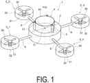
- FIG. 1 is a diagram schematically illustrating an appearance of a flight device equipped with a parachute device, helpful for understanding features of the presently claimed invention.
- a flight device 1 illustrated in FIG. 1 is, for example, a flight device being of the multi-rotor rotary wing aircraft type equipped with three or more rotors, and is a so-called drone.
- the flight device 1 includes an aircraft body unit 2, thrust force generation sections 3_1 to 3_n (n being an integer equal to or greater than 3), a parachute device 4, a notification device 5, and arm sections 6.
- the aircraft body unit 2 is a main body portion of the flight device 1. As will be described below, the aircraft body unit 2 accommodates various functional sections for controlling flying of the flight device 1. Note that in FIG. 1 , the aircraft body unit 2 having a cylindrical shape is illustrated as an example, but a shape of the aircraft body unit 2 is not particularly limited.
- the thrust force generation sections 3_1 to 3_n are rotors configured to generate a thrust force. Note that, in the following description, when each of the thrust force generation sections 3_1 to 3_n is not specifically distinguished, each of the thrust force generation sections is simply referred to as a "thrust force generation section 3".
- the number of the thrust force generation sections 3 provided in the flight device 1 is not particularly limited, but is preferably three or more.
- the flight device 1 may be any of a tricopter provided with three thrust force generation sections 3, a quadcopter provided with four thrust force generation sections 3, a hexacopter provided with six thrust force generation sections3, and an octocopter provided with eight thrust force generation sections 3.
- the thrust force generation section 3 has, for example, a structure where a propeller 30, and a motor 31 configured to rotate the propeller 30, are accommodated in a case 32 having a tube shape.
- a net for example, a resin material, a metal material (stainless steel, or the like), or the like) for preventing contact with the propeller 30 may be provided in an opening portion of the case 32 having the tube shape.
- the notification device 5 is a device for notifying the outside of the flight device 1 of danger.
- the notification device 5 is configured by including a light source formed of, for example, a light emitting diode (LED) or the like, or a sound generation device (an amplifier, a speaker, and the like).
- a light source formed of, for example, a light emitting diode (LED) or the like
- a sound generation device an amplifier, a speaker, and the like.
- the notification device 5 may be exposed to the outside of the aircraft body unit 2, or may be accommodated in the interior of the aircraft body unit 2 in a form capable of outputting light generated from a light source, sound generated from a speaker, or the like to the outside.
- the parachute device 4 is a device for slowing the falling speed of the flight device 1 and causing the flight device 1 to fall in a safe manner when an abnormality occurs in the flight device 1 and there is a risk of falling.
- the parachute device 4 is installed on the aircraft body unit 2. Note that the specific configuration of the parachute device 4 will be described later.
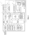
- the aircraft body unit 2 includes a power supply section 11, a sensor section 12, motor drive sections 13_1 to 13_n (n being an integer equal to or greater than 3), a flight control section 14, an abnormality detection section 15, a fall control section 16, a communication section 17, and a storage section 18.
- the flight control section 14, the abnormality detection section 15, and the fall control section 16 are achieved by, for example, cooperation between program processing by a program processing device such as a microcontroller including a central processing unit (CPU) and a storage device such as a memory and peripheral circuits (hardware resources).
- a program processing device such as a microcontroller including a central processing unit (CPU) and a storage device such as a memory and peripheral circuits (hardware resources).
- the power supply section 11 includes a battery 22 and a power supply circuit 23.
- the battery 22 is, for example, a secondary battery (for example, a lithium-ion secondary battery).
- the power supply circuit 23 is a circuit configured to generate a power supply voltage based on an output voltage of the battery 22 to supply the power supply voltage to each hardware implementing the above-described functional sections.
- the power supply circuit 23 includes, for example, a plurality of regulator circuits, and supplies a power supply voltage having an appropriate magnitude for each hardware described above.
- the sensor section 12 is a functional section for detecting a state of the flight device 1.
- the sensor section 12 detects an inclination of the aircraft body of the flight device 1.
- the sensor section 12 includes an angular velocity sensor 24, an acceleration sensor 25, a magnetic sensor 26, and an angle calculation section 27.
- the angular velocity sensor 24 is a sensor for detecting an angular velocity (rotational velocity).
- the angular velocity sensor 24 is a triaxial gyro sensor configured to detect an angular velocity based on three reference axes of an x-axis, a y-axis, and a z-axis.
- the acceleration sensor 25 is a sensor for detecting an acceleration.
- the acceleration sensor 25 is a triaxial acceleration sensor for detecting an acceleration based on three reference axes of the x-axis, the y-axis, and the z-axis.
- the magnetic sensor 26 is a sensor for detecting terrestrial magnetism.
- the magnetic sensor 26 is a triaxial geomagnetic sensor (electronic compass) for detecting an azimuth (absolute direction) based on three reference axes of the x-axis, the y-axis, and the z-axis.
- the angle calculation section 27 calculates an inclination of the aircraft body of the flight device 1 based on a detection result of at least one of the angular velocity sensor 24 and the acceleration sensor 25.
- the inclination of the aircraft body of the flight device 1 is an angle of the aircraft body (the aircraft body unit 2) with respect to the ground (horizontal direction).
- the angle calculation section 27 may calculate an angle of the aircraft body with respect to the ground based on a detection result of the angular velocity sensor 24, or may calculate an angle of the aircraft body with respect to the ground based on detection results of the angular velocity sensor 24 and the acceleration sensor 25. Note that, as a method of calculating an angle by using detection results of the angular velocity sensor 24 and the acceleration sensor 25, a known calculation equation may be used.
- the angle calculation section 27 may correct, based on a detection result of the magnetic sensor 26, the angle calculated based on the detection result of at least one of the angular velocity sensor 24 and the acceleration sensor 25.
- the sensor section 12 may include, for example, an air pressure sensor, an air volume (wind direction) sensor, an ultrasonic sensor, a GPS receiver, a camera, and the like.
- the communication section 17 is a functional section for communicating with an external device 9.
- the external device 9 is a transmitter, a server, or the like configured to control an operation of the flight device 1 and to monitor a status of the flight device 1.
- the communication section 17 is configured by, for example, a radio frequency (RF) circuit and the like. Communication between the communication section 17 and the external device 9 is achieved, for example, by wireless communication in an ISM band (2.4 GHz band).
- RF radio frequency
- the communication section 17 receives operation information of the flight device 1 transmitted from the external device 9 to output the operation information to the flight control section 14, and transmits various measurement data and the like measured by the sensor section 12 to the external device 9. In addition, when an abnormality of the flight device 1 is detected by the abnormality detection section 15, the communication section 17 transmits, to the external device 9, information indicating that an abnormality has occurred in the flight device 1. Furthermore, the communication section 17 transmits, to the external device 9, information indicating that the flight device 1 has fallen when the flight device 1 falls to the ground.
- the motor drive sections 13_1 to 13_n are provided for the respective thrust force generation sections 3, and are functional sections for driving the motors 31 to be driven in accordance with an instruction from the flight control section 14.
- each of the motor drive sections 13_1 to 13_n is simply referred to as a "motor drive section 13".
- the motor drive section 13 drives the motor 31 such that the motor 31 rotates at the number of rotations instructed from the flight control section 14.
- the motor drive section 13 is an electronic speed controller (ESC).
- the flight control section 14 is a functional section for comprehensively controlling the respective functional sections of the flight device 1.
- the flight control section 14 controls the thrust force generation sections 3 so that the flight device 1 stably flies. Specifically, the flight control section 14 calculates the appropriate number of rotations of the motor 31 of each thrust force generation section 3 so that the aircraft body stably flies in a desired direction, based on operation information received by the communication section 17 from the external device 9 (instructions for ascending, descending, advancing, retreating, and the like), and detection results of the sensor section 12, and instructs the calculated number of rotations to each motor drive section 13.
- the flight control section 14 calculates the appropriate number of rotations of the motor 31 of each thrust force generation section 3 such that the aircraft body becomes horizontal, based on a detection result of the angular velocity sensor 24 when a posture of the aircraft body is disturbed, for example, due to an external influence such as wind, and instructs the calculated number of rotations to each motor drive section 13.
- the flight control section 14 calculates the appropriate number of rotations of the motor 31 of each thrust force generation section 3 based on a detection result of the acceleration sensor 25 in order to prevent drift of the flight device 1 during hovering of the flight device 1, and instructs the calculated number of rotations to each motor drive section 13.
- flight control section 14 controls the communication section 17 to achieve transmission and reception of the various data described above to and from the external device 9.
- the storage section 18 is a functional section for storing various programs, parameters, and the like for controlling operations of the flight device 1.
- the storage section 18 is configured of a non-volatile memory such as a flash memory and a ROM, a RAM, and the like.
- the above-described parameters stored in the storage section 18 are, for example, a remaining capacity threshold value 28, an inclination threshold value 29, and the like to be described below.
- the abnormality detection section 15 is a functional section for detecting an abnormality during flying. Specifically, the abnormality detection section 15 monitors detection results of the sensor section 12, a state of the battery 22, and operation states of the thrust force generation sections 3, and determines whether the flight device 1 is in an abnormal state or not.
- the abnormal state refers to a state where autonomous flight of the flight device 1 may become impossible.
- a state where at least one of a case where the thrust force generation section 3 has broken down, a case where a remaining capacity of the battery 22 has dropped below a predetermined threshold value, and a case where the aircraft body (the aircraft body unit 2) is abnormally inclined occurs is referred to as the abnormal state.
- the abnormality detection section 15 determines that the flight device 1 is in the abnormal state.
- the "failure of the thrust force generation section 3" refers to, for example, a case where the motor 31 does not rotate at the number of rotations specified by the flight control section 14, a case where the propeller 30 does not rotate, a case where the propeller 30 has broken down, and the like.
- the abnormality detection section 15 determines that the flight device 1 is in the abnormal state.
- the remaining capacity threshold value 28 may be such a capacity value that the motor cannot rotate at the number of rotations instructed by the flight control section 14, for example.
- the remaining capacity threshold value 28 is stored in advance in the storage section 18, for example.
- the abnormality detection section 15 determines that the flight device 1 is abnormal. For example, the abnormality detection section 15 determines that the flight device 1 is in the abnormal state when a state where an angle calculated by the angle calculation section 27 exceeds a predetermined threshold value (hereinafter, also referred to as the "inclination threshold value") 29 continues for a predetermined period of time.
- a predetermined threshold value hereinafter, also referred to as the "inclination threshold value"
- An angle (pitch angle) of movement of the flight device 1 in a front and rear direction and an angle (roll angle) of movement of the flight device 1 in a left and right direction are obtained in advance by an experiment, and then, the inclination threshold value 29 may be set to a value larger than these angles.
- the inclination threshold value 29 is stored in advance in the storage section 18, for example.
- a fall control section (one example of a parachute control section) 16 is a functional section for controlling falling of the flight device 1. Specifically, when the abnormality detection section 15 detects that the flight device 1 is in the abnormal state, the fall control section 16 performs fall preparation processing for causing the flight device 1 to fall in a safe manner.
- the fall control section 16 performs the following processing as the fall preparation processing.
- the fall control section 16 controls the notification device 5 in response to the detection of the abnormality by the abnormality detection section 15, and notifies the outside of a dangerous state.
- the fall control section 16 controls the respective motor drive sections 13 in response to the detection of the abnormality by the abnormality detection section 15 to stop the rotation of each motor 31.
- the fall control section 16 outputs a control signal indicating opening of a parachute to the parachute device 4 to open a parachute 400.
- FIG. 3 is a diagram schematically illustrating a configuration of the parachute device 4 according to a first example not covered by the presently claimed invention.
- a side cross section of the parachute device 4 is illustrated in the same figure.
- the parachute device 4 includes a parachute 400, a parachute accommodation section 40, ejection sections 41, an ejection control section 42, and flying bodies 43.
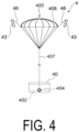
- FIG. 4 is a diagram schematically illustrating a state with the parachute 400 being open.
- the parachute 400 includes a parachute body (canopy) 406, and a hanging line 407 connecting the parachute body 406 and the parachute accommodation section 40 (a parachute attachment section 404).
- the parachute body 406 is connected to the flying bodies 43 by the connection lines 46.
- the connection line 46 is connected to the parachute body 406 at an edge (peripheral edge) side from an apex of the parachute body 406. More specifically, the respective connection lines 46 are connected to a peripheral edge portion of the parachute 400 in a separated manner from one another.
- each connection line 46 is connected along the circumferential direction of the peripheral edge portion of the parachute 400 at equal intervals.
- connection line 46 may be connected to the peripheral edge portion of the parachute 400.
- positions at the peripheral edge portion of the parachute 400 connected with the connection lines 46 are not particularly limited.
- connection line 46 is formed of, for example, a metal material (for example, stainless steel) or a fiber material (for example, a nylon string).
- a diameter D of the parachute body 406 required to cause the flight device 1 to fall at a low speed can be calculated based on the following Equation (1).
- Equation (1) m is a total weight of the flight device 1
- v is a falling speed of the flight device 1
- ⁇ is an air density
- Cd is a resistance coefficient.
- D 2 v 2 mg ⁇ ⁇ Cd
- a diameter D of the parachute body 406 required to make the falling speed v of the flight device 1 be 5 (m/s) is calculated to be 14.6 (m) from Equation (1).
- the parachute 400 is accommodated in the parachute accommodation section 40 with the parachute body 406 folded before its use.
- the parachute accommodation section 40 is a container configured to accommodate the parachute 400.
- the parachute accommodation section 40 is configured of, for example, resin.
- the parachute accommodation section 40 is set on an upper surface of the aircraft body unit 2, that is, on a surface at an opposite side to the ground during flying of the flight device 1.
- the parachute accommodation section 40 is preferably installed such that the central axis O of the aircraft body unit 2 and a central axis P of the parachute accommodation section 40 overlap with each other on the upper surface of the aircraft body unit.
- the parachute accommodation section 40 has, for example, a cylindrical shape having an opening at one end and having a bottom at the other end.
- the parachute accommodation section 40 includes a side wall portion 401 having a tube shape (for example, a cylindrical shape) and a bottom portion 402 formed so as to close an opening at one end side of the side wall portion 401.
- a side wall portion 401 having a tube shape (for example, a cylindrical shape) and a bottom portion 402 formed so as to close an opening at one end side of the side wall portion 401.
- the side wall portion 401 and the bottom portion 402 define an accommodation space 403 for accommodating the parachute 400. Note that the side wall portion 401 and the bottom portion 402 may be individually formed and then joined, or may be integrally formed.
- the bottom portion 402 is provided with the parachute attachment section 404 for connecting the parachute accommodation section 40 and the parachute 400.
- the parachute 400 and the parachute accommodation section 40 are connected.
- parachute accommodation section 40 may be provided with a lid covering the opened one end side of the side wall portion 401 in a state with the parachute 400 accommodated in the accommodation space 403.
- the flying body 43 is a device configured to discharge the parachute 400 to the outside of the parachute accommodation section 40 to assist the opening (deployment) of the parachute 400.
- the flying body 43 obtains a thrust force, for example, by spraying gas.
- the flying body 43 is connected to the parachute 400 through the connection line 46 as described above.
- the parachute device 4 includes at least one flying body 43.
- the parachute device 4 preferably includes three or more flying bodies 43.
- a case of the parachute device 4 including three flying bodies will be exemplified and described. Note that a specific configuration of the flying body 43 will be described below.
- the ejection section 41 is a device configured to hold the flying body 43 to eject the held flying body 43.
- the ejection section 41 is provided for each flying body 43.
- the parachute device 4 according to the present embodiment includes three ejection sections 41 for separately accommodating three flying bodies 43.
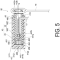
- FIG. 5 is a diagram illustrating a configuration of a flying body ejection mechanism according to a first example not covered by the presently claimed invention.
- the ejection section 41 is formed in a tube shape (for example, a cylindrical shape) having an opening at one end and having a bottom at the other end.
- the ejection section 41 includes, for example, a side wall portion 411 having a cylindrical shape and a bottom portion 412 covering one end of the side wall portion 411.
- the side wall portion 411 and the bottom portion 412 define an accommodation space for accommodating the flying body 43.
- the side wall portion 411 and the bottom portion 412 are formed of, for example, resin.
- Each ejection section 41 is provided in the parachute accommodation section 40. Specifically, as illustrated in FIG. 1 and the like, each ejection section 41 is joined to an outer peripheral surface of the parachute accommodation section 40 such that an ejection port 413 being an opening portion formed at an end portion at an opposite side to the bottom portion 412 in the side wall portion 411 faces the opened one end side of the parachute accommodation section 40.
- each of the ejection sections 41 is disposed at equal intervals in a rotational direction with the central axis P of the parachute accommodation section 40 as a center.
- a position on the outer peripheral surface of the parachute accommodation section 40 joined with the ejection section 41 is not particularly limited.
- the flying body 43 includes a gas generating device 45 and a flying body main body section 44. As illustrated in FIG. 5 , the flying body 43 is disposed such that the flying body main body section 44 is inserted in an interior of the ejection section 41 at one end side, and the gas generating device 45 faces the bottom portion 412 (a bottom surface 412a) of the ejection section 41 in the interior of the ejection section 41.
- the gas generating device 45 is a device configured to generate gas serving as a base of a thrust force for ejecting the flying body 43 to the outside from the ejection port 413 of the ejection section 41.
- the gas generating device 45 includes a housing 451, a sealing member 452, an ignition agent 453, a gas generating agent 454, and an ignition section (not illustrated).
- the ignition section is electrically connected to the ejection control section 42 to be described later through a lead wire (conductive wire) 47.
- the ignition section ignites the ignition agent 453 in response to an ignition signal output from the ejection control section 42, and causes the gas generating agent 454 to chemically react to generate gas.
- the housing 451 is a housing including a gas discharge chamber 455 configured to house the ignition agent 453 and the gas generating agent 454 and to discharge the gas generated from the gas generating agent 454.
- the housing 451 has a dome shape.
- the housing 451 is configured of, for example, resin.
- the housing 451 is configured of fiber-reinforced plastics (FRP) or the like. Note that the housing 451 is not limited to being made of resin, and may be configured of metal.
- the gas discharge chamber 455 is filled with the gas generating agent 454.
- a gas discharge hole 456 for discharging gas generated from the gas generating agent 454 is formed in the gas discharge chamber 455.
- the gas discharge chamber 455 is provided with the sealing member 452 covering the gas discharge hole 456 to seal the gas generating agent 454 in the gas discharge chamber 455.
- the sealing member 452 is configured of a material to be easily destroyed by a pressure of the generated gas.
- the sealing member 452 is, for example, a thin film such as polyester.
- the gas generating device 45 is disposed in an internal space 440 defined by the ejection section 41 and the flying body main body section 44.
- the flying body main body section 44 is a component configured to hold the gas generating device 45 and connected to the connection line 46.
- the flying body main body section 44 is formed, for example, in a bar shape. More specifically, the flying body main body section 44 is formed in a partially hollow cylindrical shape, for example.
- the flying body main body section 44 is engaged with the ejection section 41.
- the flying body main body section 44 has the gas generating device 45 at one end, and is connected to the connection line 46 at the other end.
- the flying body main body section 44 is separated into two functional sections of a holding section 441 configured to hold the gas generating device 45 in the axis Q direction of the flying body main body section 44, and a connection section 442 for connecting with the connection line 46.
- the flying body main body section 44 is configured of, for example, resin.
- the holding section 441 and the connection section 442 may be integrally formed, for example, as a resin molded article, or may be formed as separated components and then joined to each other.
- the flying body main body section 44 will be described as a component integrally molded with the holding section 441 and the connection section 442.
- the holding section 441 houses and holds the gas generating device 45 in the interior. Specifically, the holding section 441 holds the gas generating device 45 in the interior of the ejection section 41 such that the gas discharge side of the gas generating device 45, that is, the gas discharge hole 456 (sealing member 452) side of the housing 451, faces the bottom portion 412 (bottom surface 412a) of the ejection section 41.
- the holding section 441 includes a hole 441a formed so as to correspond to the shape of the gas generating device 45. For example, by press-fitting or adhering the gas generating device 45 to the hole 441a, the holding section 441 holds the gas generating device 45.
- connection section 442 is formed so as to protrude to a side opposite to the holding section 441 in a direction parallel to the axis Q of the flying body main body section 44.
- the connection section 442 is formed in a tube shape (for example, a cylindrical shape).
- the connection section 442 includes a locking section 442a for locking the connection line 46 at an end portion at an opposite side to the holding section 441.
- the locking section 442a is, for example, a through hole.
- the connection line 46 is locked to the locking section 442a while being inserted through the through hole as the locking section 442a.
- the lead wire 47 extends in an interior of the connection section 442 having a tube shape.
- the lead wire 47 is configured of, for example, a vinyl wire, a tin-plated wire, an enamel wire, or the like.
- the lead wire 47 is routed in the internal space 442b of the connection section 442, and is connected to the gas generating device 45 held by the holding section 441 through a through hole 441b formed at the bottom surface of the holding section 441 of the flying body main body section 44.
- the flying body 43 may be secured to the ejection section 41 by using a pin (shear pin) 48.
- a pin shear pin
- a through hole 480 is formed at the side wall portion 411 of the ejection section 41, and a hole (for example, a non-through hole) is formed at the flying body main body section 44 of the flying body 43.
- the pin 48 is inserted into the through hole 480 at the side wall portion 411 side and the hole at the flying body main body section 44 side. Due to this, the flying body 43 is secured to the ejection section 41 when the parachute device 4 is not in use.
- the pin 48 is configured to be destructive by a force applied to the pin 48 in the axis Q direction of the flying body main body section 44 when the flying body 43 is ejected. This may not disturb the ejection of the flying body 43 due to the pin 48.
- aluminum alloys, resin, and the like may be preferably used for the pin 48.
- the flying body 43 is disposed in the interior of the ejection section 41 with the gas generating device 45 (sealing member 452) spaced apart from and facing the bottom portion 412 (bottom surface 412a) of the ejection section 41. This forms a space 418 between the gas generating device 45 of the flying body 43 and the bottom portion 412 of the ejection section 41.
- a distance between the gas generating device 45 of the flying body 43 and the bottom portion 412 of the ejection section 41 can be changed as appropriate so that a pressure of gas for ejecting the flying body 43 is appropriate.
- the ejection control section 42 is a functional section configured to perform control for ejecting the flying body 43 from the ejection section 41.
- the ejection control section 42 outputs an ignition signal when a control signal indicating the opening of the parachute 400 is output from the fall control section 16, for example.
- the ignition signal is input to an ignition section (not illustrated) of the gas generating device 45 provided in each flying body 43 through the lead wire 47, and the ignition section ignites the ignition agent 453 in response to the input ignition signal.
- the fall control section 16 at the flight device 1 side or the fall control section 16A at the parachute device 4 side transmits a control signal indicating the opening of the parachute 400 to the ejection control section 42 of the parachute device 4.
- the ejection control section 42 of the parachute device 4 outputs an ignition signal when the control signal indicating the opening of the parachute 400 is received.
- the ignition signal is transmitted to the ignition section (not illustrated) of the gas generating device 45 through the lead wire 47.
- the ignition section of the gas generating device 45 ignites the ignition agent 453 and causes the gas generating agent 454 to chemically react, and gas is generated in the gas discharge chamber 455.
- the sealing member 452 covering the gas discharge hole 456 is broken. This causes the gas in the gas discharge chamber 455 to be discharged from the gas discharge hole 456 into the space 418 in the ejection section 41, and the space 418 is filled with the gas.
- the flying body 43 is moved toward the ejection port 413 side due to the pressure of the gas, and is ejected from the ejection port 413 of the ejection section 41.
- each flying body 43 When the flying body 43 is ejected from each ejection section 41, each flying body 43 pulls the parachute 400 through the connection line 46. This causes the parachute 400 to be discharged from the parachute accommodation section 40. After that, for the parachute 400 further pulled by each flying body 43, the parachute body 406 is expanded by the air entering in the interior of the parachute body 406 in the folded state. This causes the parachute 400 to open.
- FIG. 6 is a diagram schematically illustrating a state with the parachute 400 of the flight device 1 according to the presently claimed invention being opened.
- each flying body 43 pulls the parachute body 406 of the discharged parachute 400 from its apex portion toward the edge (peripheral edge) side. This allows the parachute body 406 to be expanded and easily filled with the air, and thus, allows the parachute 400 to be immediately opened.
- the parachute device 4 includes at least one flying body 43 connected to the parachute 400, and the flying body 43 includes the flying body main body section 44 engaged with the ejection section 41, and the gas generating device 45 disposed in the internal space 440 defined by the ejection section 41 and the flying body main body section 44.
- the flying body 43 can be made to fly from the ejection section 41.
- the flight of the flying body 43 allows the parachute body 406 of the parachute 400 connected to the flying body 43 to be pulled from its apex portion to the edge (peripheral edge) side, allowing the parachute body 406 to be more easily filled with the air and allowing the parachute 400 to be immediately opened.
- the parachute can be quickly and reliably opened by attaching the parachute device 4 according to the present embodiment.
- the flying body 43 itself is provided with the gas generating device 45 as a thrust force generation device. This makes it possible to suppress an increase in the weight of the parachute device 4 as it is not necessary to provide the thrust force generation device in the parachute device 4 separately from the flying body 43, and makes it possible to reduce the cost.
- each flying body 43 includes the gas generating device 45, it is easy to control the ejection timing for each flying body 43.
- a single gas generating device is provided as the thrust force generation device in the parachute device 4 and the gas generated from the gas generating device is discharged to the flying bodies, all of the flying bodies can only be simultaneously ejected.
- the parachute device 4 according to the present embodiment it is easy to change the timing of ejecting the plurality of flying bodies 43.
- the degree of freedom of control of the parachute device 4 can be increased.
- the flying body 43 is disposed in a state with the flying body main body section 44 holding the gas generating device 45 inserted in the interior of the ejection section 41 at one end, and with the gas generating device 45 facing the bottom portion 412 of the ejection section 41 in the interior of the ejection section 41.
- the gas generating device 45 is housed in the interior of the ejection section 41, and thus, it is possible to prevent degradation or the like of the gas generating device 45 due to rainwater or foreign matter being exposed to the gas generating device 45.
- the flying body 43 is accommodated in the ejection section 41, when the gas generating device 45 is ignited, gas generated from the gas generating device 45 is stored in the ejection section 41 to increase a gas pressure, the flying body 43 can be vigorously ejected.
- the inner peripheral surface of the ejection section 41 formed in a tube shape functions as a guide mechanism configured to guide movement of the flying body 43 at the time of ejection, allowing the flying body 43 to more linearly fly.
- the flying body main body section 44 includes the holding section 441 configured to hold the gas generating device 45, and the connection section 442 connected to the connection line 46 and formed so as to protrude to a side opposite to the holding section 441 in the axis Q direction of the flying body main body section 44.
- connection line 46 can easily achieve connection of the flying body 43 and the parachute 400 by using the connection line 46 while stably holding the flying body 43 by the ejection section 41.
- connection section 442 is formed in a tube shape, and at least a part of the lead wire 47 for igniting the gas generating device 45 is routed in the interior of the connection section 442.
- the weight of the parachute device 4 can be reduced by configuring the parachute accommodation section 40, the ejection section 41, the flying body main body section 44, and the like by using resin (for example, synthetic resin).
- FIG. 7 is a diagram schematically illustrating a configuration of a parachute device 4A according to the presently claimed invention. A side cross section of the parachute device 4A is illustrated in the same figure.
- the parachute device 4A according to the presently claimed invention differs from the parachute device 4 according to the first example in the structures of the flying body and the ejection section, and is similar to the parachute device 4 according to the first example in other respects.
- FIG. 8 is a diagram illustrating a configuration of a flying body ejection mechanism 50A including a flying body 43A and an ejection section 41A according to the presently claimed invention.
- the flying body 43A is disposed on the ejection section 41A so as to cover at least a part of an outer peripheral surface of the ejection section 41A. Specifically, as illustrated in FIG. 8 , the flying body 43A is supported on the ejection section 41A with at least a part of the ejection section 41A inserted in an interior of a flying body main body section 44A and with the gas generating device 45 facing a tip end portion 414A of the ejection section 41A.
- the flying body 43A includes the gas generating device 45 and the flying body main body section 44A.
- the gas generating device 45 is disposed in an internal space 440A defined by the ejection section 41A and the flying body main body section 44A.
- the flying body main body section 44A is formed into a tube shape (for example, a cylindrical shape) having an opening at one end and having a bottom at the other end.
- the flying body main body section 44A is configured of resin, for example.
- the gas generating device 45 is provided in the interior of the flying body main body section 44A.
- the flying body main body section 44A is inserted through the ejection section 41A at the opening portion side of the tube, holds the gas generating device 45 at the bottom portion side of the tube, and is connected to the connection line 46 at an end portion at an opposite side to the opening portion with the bottom portion interposed.
- the flying body main body section 44A is divided into three functional sections of a supporting section 443A for supporting the flying body 43A at the ejection section 41A along the axis Q of the flying body main body section 44A, a holding section 441A for holding the gas generating device 45, and a connection section 442A for connecting with the connection line 46.
- the supporting section 443A, the holding section 441A, and the connection section 442A may be integrally formed, for example, as a resin molded article, or may be formed as separated components and joined to each other.
- the flying body main body section 44A will be described as a component integrally molded with the supporting section 443A, the holding section 441A, and the connection section 442A.
- the supporting section 443A is formed in a tube shape (for example, a cylindrical shape).
- An inner diameter of the supporting section 443A has a size corresponding to an outer diameter of the ejection section 41A.
- At least a part of the ejection section 41A is inserted into the supporting section 443A from one end side.
- the tip end portion 414A of the ejection section 41A is inserted into the interior of the supporting section 443A from one end side of the supporting section 443A.
- the holding section 441A includes, for example, a hole 441Aa formed so as to correspond to the shape of the gas generating device 45.
- the holding section 441A holds the gas generating device 45 by, for example, press-fitting or adhering the gas generating device 45 to the hole 441Aa.
- the holding section 441A holds the gas generating device 45 at the other end side of the supporting section 443A with the holding section 441A facing the tip end portion 414A of the ejection section 41A inserted from one end side of the supporting section 443A. That is, the gas generating device 45 is disposed such that the gas discharge side of the gas generating device 45, that is, the gas discharge hole 456 (sealing member 452) side of the housing 451 faces the tip end portion 414A of the ejection section 41A.
- the flying body 43A is disposed with the gas generating device 45 (sealing member 452) spaced apart from and facing the tip end portion 414A (tip end surface 414Aa) of the ejection section 41A. This forms a space 418A between the gas generating device 45 of the flying body 43A and the tip end portion 414A of the ejection section 41A.
- a distance between the gas generating device 45 of the flying body 43A and the tip end portion 414A of the ejection section 41A can be changed as appropriate so that the pressure of gas for ejecting the flying body 43A becomes appropriate.
- connection section 442A is formed so as to protrude from the holding section 441A to a side opposite to the supporting section 443A in a direction parallel to the axis Q of the flying body main body section 44A.
- the connection section 442A is formed, for example, in a tube shape (for example, a cylindrical shape) having an opening at one end and having a bottom at the other end.
- connection section 442A is connected to the connection line 46.
- connection section 442A has the locking section 442Aa for locking the connection line 46 at an end portion at an opposite side to the supporting section 443A.
- the locking section 442Aa is, for example, a through hole.
- the connection line 46 is locked to the locking section 442Aa while being inserted through the through hole serving as the locking section 442Aa.
- the lead wire 47 extends in the interior of the connection section 442A having a tube shape.
- the lead wire 47 is routed in the internal space 442Ab of the connection section 442A, and is connected to the gas generating device 45 held by the holding section 441A through a through hole 441Ab formed at the bottom surface of the holding section 441A of the flying body main body section 44A.
- the flying body 43A is supported on the ejection section 41A with at least a part of the ejection section 41A formed in a bar shape inserted in the interior of the flying body main body section 44A and with the gas generating device 45 facing the tip end portion 414A of the ejection section 41A.
- the gas generating device 45 is sealed by the ejection section 41A with the gas generating device 45 accommodated in the interior of the flying body main body section 44A, it is possible for the gas generating device 45 to prevent degradation of the gas generating device 45 due to exposure to rainwater or foreign matter.
- the flying body main body section 44A is disposed so as to cover (so as to put on a lid over) the ejection section 41A having a bar shape, even when the flying body 43A is exposed to rain or wind when the parachute device 4Ais disposed in the flight device 1, it is difficult for rainwater or foreign matter to enter in the interior of the flying body main body section 44A.
- the gas generated by the gas generating device 45 is stored in a space defined by the inner wall surface of the supporting section 443A and the tip end surface 414Aa of the ejection section 41A to increase the gas pressure, and as a result, the flying body 43A can be vigorously ejected.
- a side surface 41Aa of the ejection section 41A functions as a guide mechanism configured to guide movement of the flying body 43A at the time of ejection, allowing the flying body 43A to more linearly fly.
- the gas generating device 45 is provided at the other end side (at the holding section 441A side) of the supporting section 443A having a tube shape, the gas generated by the gas generating device 45 continues to be discharged from the one end side through the interior of the supporting section 443A even after the flying body 43A is ejected from the ejection section 41A. This allows the flying body 43A to linearly fly after the ejection of the flying body 43A.
- the flying body 43A is designed to have the same outer diameter dimension as that of the flying body 43 according to the first example, a weight of the flying body 43A is larger than that of the flying body 43, so that an inertial force when the flying body 43A is ejected is larger than that of the flying body 43. As a result, the parachute 400 is more easily opened.
- connection section 442A of the flying body 43A is formed in a cylindrical shape, and at least a part of the lead wire 47 for igniting the gas generating device 45 is routed in the interior of the connection section 442A.
- the ejection control section 42 is provided in the parachute device 4, 4A, but the present invention is not limited to this.
- the ejection control section 42 may be provided in the flight device 1.
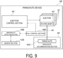
- a parachute device 4B may include an abnormal state detection mechanism including a sensor section 12B, an abnormality detection section 15B, and a fall control section 16B.
- the sensor section 12B, the abnormality detection section 15B, and the fall control section 16B respectively have similar functions to those of the sensor section 12, the abnormality detection section 15, and the fall control section 16. This allows the parachute device 4, 4B itself to detect an abnormal state to eject the flying body 43, 43A.
- the aircraft body unit 2 may or may not have an abnormal state detection mechanism including the sensor section 12, the abnormality detection section 15, and the fall control section 16.
- Both of the aircraft body unit 2 and the parachute device 4B have an abnormal state detection mechanism, and thus, even when one abnormal state detection mechanism cannot detect an abnormal state due to some causes, it is possible to detect the abnormal state by the other abnormal state detection mechanism to more reliably open the parachute 400.
- the parachute accommodation section 40 may have a space for accommodating the parachute 400 in the interior, and may be formed, for example, in a polygonal column (for example, quadrangular prism) shape.
- the flying body 43, 43A is disposed such that a space 418 is formed between the gas generating device 45 and the ejection section 41, 41A, but the present invention is not limited to this. That is, when sufficient gas pressure can be obtained in order to eject the flying body 43, 43A, the gas generating device 45 may be disposed in contact with the ejection section 41, 41A (the bottom surface 412a, the tip end surface 414Aa).
- the examples have been given that the outer shape of the ejection section 41, 41A is cylindrical, but the present invention is not limited to this. That is, the ejection section 41 may have a structure accommodating the flying body 43 in the interior, and being capable of ejecting the flying body 43, for example, the outer shape may be a polygonal column (for example, quadrangular prism) shape, and the internal space accommodating the flying body 43 may be cylindrical. Similarly, the ejection section 41A may have a structure that the flying body 43A is disposed outside and the flying body 43A can be ejected, and for example, the outer shape may be a polygonal column (for example, quadrangular prism) shape. However, in that case, the internal shape of the flying body 43A needs to be matched to the ejection section 41A.
- the parachute device 4, 4A may be provided with a mechanism for preventing incorrect ejection of the flying body 43, 43A.
- a safety pin is provided in the parachute device 4, 4A, and when the safety pin is inserted, the parachute device 4, 4A may not operate, and when the safety pin is detached, the parachute device 4, 4A may become operable.
- the flight control section 14 and the like serving as functional sections for controlling flying in a normal state
- the abnormality detection section 15, the fall control section 16, and the storage section 18 serving as functional sections for performing fall control at the time of occurrence of an abnormality are operated by power supply from the same battery 22, but the present invention is not limited this.
- a battery for a functional section for controlling flying in a normal state and a battery for a functional section for performing fall control at the time of occurrence of an abnormality may be separately prepared. According to this, even when an abnormality occurs in the battery for the functional section for controlling flying in the normal state and power cannot be supplied, the fall control processing can be performed.
- the functional section for performing fall control at the time of occurrence of an abnormality may be configured such that the power supply from the two batteries described above can be selected. This enables the fall control processing to be reliably performed because even when an abnormality occurs in one battery, power can be supplied from the other battery.
- a shock absorbing member such as an airbag may be provided at the lower surface of the aircraft body unit 2. In this way, the safety of the flight device 1 during falling can be further improved.
Landscapes
- Engineering & Computer Science (AREA)
- Aviation & Aerospace Engineering (AREA)
- Chemical & Material Sciences (AREA)
- Combustion & Propulsion (AREA)
- Mechanical Engineering (AREA)
- Toys (AREA)
Claims (6)
- Flugkörper-Auswurfmechanismus (50A), umfassend:
einen Flugkörper (43A), der dazu in der Lage ist, mit einem Fallschirm (400) verbunden zu sein;und einen Auswurfabschnitt (41A), der dazu konfiguriert ist, den Flugkörper zu halten und den gehaltenen Flugkörper auszuwerfen, wobei der Flugkörper einen Flugkörper-Hauptkörperabschnitt (44A) umfasst, der mit dem Auswurfabschnitt im Eingriff ist, undeine Gaserzeugungsvorrichtung (45), die in einem Innenraum (440A), der durch den Auswurfabschnitt und den Flugkörper-Hauptkörperabschnitt definiert ist, angeordnet ist und dazu konfiguriert ist, Gas zu erzeugen, gekennzeichnet dadurch, dassder Auswurfabschnitt stabförmig ausgebildet ist,der Flugkörper-Hauptkörperabschnitt rohrförmig ausgebildet ist und eine Öffnung an einem Ende aufweist und einen Boden an einem anderen Ende aufweist,die Gaserzeugungsvorrichtung in einem Inneren des Flugkörper-Hauptkörperabschnitts bereitgestellt ist, undder Flugkörper auf dem Auswurfabschnitt so getragen wird, dass zumindest ein Teil des Auswurfabschnitts in ein Inneres des Flugkörper-Hauptkörperabschnitts hineingesteckt ist und die Gaserzeugungsvorrichtung einem Spitzenendbereich (414A) des Auswurfabschnitts zugewandt ist. - Fallschirmvorrichtung (4A), umfassend:einen Fallschirm (400);einen Fallschirm-Unterbringungsabschnitt (40), der dazu konfiguriert ist, den Fallschirm unterzubringen;den Flugkörper-Auswurfmechanismus nach Anspruch 1, wobei der Flugkörper mit dem Fallschirm verbunden ist.
- Fallschirmvorrichtung nach Anspruch 2, ferner umfassend:eine Verbindungsleine (46), die den Fallschirm und den Flugkörper verbindet, wobei der Flugkörper-Hauptkörperabschnitt Folgendes beinhaltet: einen Trägerabschnitt (443A), der rohrförmig ausgebildet und in den zumindest ein Teil des Auswurfabschnitts von einer Endseite aus hineingesteckt ist, einen Halteabschnitt (441A), der dazu konfiguriert ist, die Gaserzeugungsvorrichtung an einer anderen Endseite des Trägerabschnitts so zu halten, dass die Gaserzeugungsvorrichtung einem Spitzenendbereich (414A) des Auswurfabschnitts, der von der einen Endseite des Trägerabschnitts aus hineingesteckt ist, zugewandt ist, undeinen Verbindungsabschnitt (442A), der so ausgebildet ist, dass er von dem Halteabschnitt zu einer dem Trägerabschnitt gegenüberliegenden Seite hin vorsteht, und mit der Verbindungsleine verbunden ist.
- Fallschirmvorrichtung nach Anspruch 3, ferner umfassend:
einen Leitungsdraht (47), der dazu konfiguriert ist, die Gaserzeugungsvorrichtung zu entzünden, wobei der Verbindungsabschnitt rohrförmig ausgebildet ist und zumindest ein Teil des Leitungsdrahtes in einem Inneren des Verbindungsabschnitts verläuft. - Fallschirmvorrichtung nach einem der Ansprüche 2 bis 4, ferner umfassend:einen Unregelmäßigkeitenerkennungsabschnitt (15B), der dazu konfiguriert ist, eine Unregelmäßigkeit während des Fliegens zu erkennen; undeinen Fallschirmsteuerabschnitt (16B), der dazu konfiguriert ist, den Flugkörper dazu zu veranlassen, als Reaktion auf die Erkennung der Unregelmäßigkeit durch den Unregelmäßigkeitenerkennungsabschnitt von dem Auswurfabschnitt ausgeworfen zu werden.
- Flugvorrichtung (1), umfassend:
eine Flugzeugkörpereinheit (2)einen Schubkrafterzeugungsabschnitt (3, 3_1 bis 3_n), der mit der Flugzeugkörpereinheit verbunden ist und dazu konfiguriert ist, eine Schubkraft zu erzeugen;einen Flugsteuerabschnitt (14), der dazu konfiguriert ist, den Schubkrafterzeugungsabschnitt zu steuern;einen Unregelmäßigkeitenerkennungsabschnitt (15B), der dazu konfiguriert ist, eine Unregelmäßigkeit während des Fliegens zu erkennen;die Fallschirmvorrichtung nach einem der Ansprüche 2 bis 5; undeinen Fallschirmsteuerabschnitt (16B), der dazu konfiguriert ist, den Flugkörper dazu zu veranlassen, als Reaktion auf die Erkennung der Unregelmäßigkeit durch den Unregelmäßigkeitenerkennungsabschnitt von dem Auswurfabschnitt ausgeworfen zu werden.
Applications Claiming Priority (2)
| Application Number | Priority Date | Filing Date | Title |
|---|---|---|---|
| JP2019027795A JP7128131B2 (ja) | 2019-02-19 | 2019-02-19 | パラシュート装置、飛行装置、飛翔体射出機構 |
| PCT/JP2019/050809 WO2020170603A1 (ja) | 2019-02-19 | 2019-12-25 | パラシュート装置、飛行装置、飛翔体射出機構 |
Publications (3)
| Publication Number | Publication Date |
|---|---|
| EP3929079A1 EP3929079A1 (de) | 2021-12-29 |
| EP3929079A4 EP3929079A4 (de) | 2022-10-19 |
| EP3929079B1 true EP3929079B1 (de) | 2024-06-26 |
Family
ID=72144059
Family Applications (1)
| Application Number | Title | Priority Date | Filing Date |
|---|---|---|---|
| EP19915908.8A Active EP3929079B1 (de) | 2019-02-19 | 2019-12-25 | Fallschirmvorrichtung, fluggerät und flugkörperausstossmechanismus |
Country Status (5)
| Country | Link |
|---|---|
| US (1) | US11753173B2 (de) |
| EP (1) | EP3929079B1 (de) |
| JP (1) | JP7128131B2 (de) |
| CN (1) | CN113453983B (de) |
| WO (1) | WO2020170603A1 (de) |
Families Citing this family (4)
| Publication number | Priority date | Publication date | Assignee | Title |
|---|---|---|---|---|
| JP7128155B2 (ja) * | 2019-07-24 | 2022-08-30 | ミネベアミツミ株式会社 | パラシュート装置および飛行装置 |
| JP1714249S (ja) | 2021-09-03 | 2022-05-09 | ドローン用パラシュート格納器 | |
| CN114671022A (zh) * | 2022-04-01 | 2022-06-28 | 深圳市瑞源精密工业有限公司 | 一种具有降落缓冲装置的无人机 |
| CN116477056B (zh) * | 2023-03-13 | 2023-10-27 | 中国气象局广州热带海洋气象研究所(广东省气象科学研究所) | 基于无人机的大气黑碳垂直廓线监测装置 |
Family Cites Families (14)
| Publication number | Priority date | Publication date | Assignee | Title |
|---|---|---|---|---|
| US2924409A (en) * | 1956-12-06 | 1960-02-09 | Experiment Inc | Parachute device |
| JPS63220100A (ja) * | 1987-03-10 | 1988-09-13 | 株式会社東芝 | 発射装置の飛翔体固定装置 |
| JP4785084B2 (ja) | 2008-06-09 | 2011-10-05 | 防衛省技術研究本部長 | パラシュート取付装置 |
| IL229068A (en) * | 2013-10-24 | 2016-06-30 | Amir Tsaliah | Facility and method for rapid parachute deployment |
| CN104326086B (zh) * | 2014-10-22 | 2016-07-06 | 襄阳宏伟航空器有限责任公司 | 降落伞快速开伞装置 |
| US10106264B1 (en) | 2016-08-26 | 2018-10-23 | Kitty Hawk Corporation | Rocket-based inverted parachute deployment system |
| CN106428575B (zh) * | 2016-11-24 | 2019-05-21 | 江苏飞图智能控制技术有限公司 | 一种小型降落伞的发射系统 |
| JP6866143B2 (ja) | 2016-12-12 | 2021-04-28 | 株式会社自律制御システム研究所 | 無人航空機 |
| JP6797057B2 (ja) | 2017-03-29 | 2020-12-09 | 日本化薬株式会社 | パラシュート展開装置 |
| JP7046923B2 (ja) * | 2017-04-11 | 2022-04-04 | 日本化薬株式会社 | 飛行体および飛行体の制御方法 |
| JP7062495B2 (ja) | 2017-05-16 | 2022-05-06 | 日本化薬株式会社 | パラシュートまたはパラグライダー展開装置およびこれを備えた飛行体 |
| JP2019014320A (ja) | 2017-07-04 | 2019-01-31 | 日本化薬株式会社 | パラシュート又はパラグライダー展開装置およびこれを備える無人航空機 |
| CN107933933A (zh) * | 2017-11-26 | 2018-04-20 | 合肥赛为智能有限公司 | 一种无人机降落伞新型弹射结构装置 |
| EP3858737A4 (de) * | 2018-09-28 | 2022-06-08 | Nipponkayaku Kabushikikaisha | Mit einem zu entfaltenden körper ausgestatteter flugkörper |
-
2019
- 2019-02-19 JP JP2019027795A patent/JP7128131B2/ja active Active
- 2019-12-25 US US17/429,056 patent/US11753173B2/en active Active
- 2019-12-25 EP EP19915908.8A patent/EP3929079B1/de active Active
- 2019-12-25 WO PCT/JP2019/050809 patent/WO2020170603A1/ja not_active Ceased
- 2019-12-25 CN CN201980092380.7A patent/CN113453983B/zh active Active
Also Published As
| Publication number | Publication date |
|---|---|
| CN113453983A (zh) | 2021-09-28 |
| WO2020170603A1 (ja) | 2020-08-27 |
| CN113453983B (zh) | 2024-11-19 |
| US20220127006A1 (en) | 2022-04-28 |
| EP3929079A1 (de) | 2021-12-29 |
| US11753173B2 (en) | 2023-09-12 |
| JP2020131917A (ja) | 2020-08-31 |
| JP7128131B2 (ja) | 2022-08-30 |
| EP3929079A4 (de) | 2022-10-19 |
Similar Documents
| Publication | Publication Date | Title |
|---|---|---|
| US11820522B2 (en) | Parachute device, flight device, and flying body ejection mechanism | |
| US11745873B2 (en) | Flying apparatus | |
| EP3929079B1 (de) | Fallschirmvorrichtung, fluggerät und flugkörperausstossmechanismus | |
| EP3611096A1 (de) | Luftfahrzeug und verfahren zur steuerung eines luftfahrzeugs | |
| US11884407B2 (en) | Parachute device, flight device, and flying body ejection mechanism | |
| JP7237028B2 (ja) | 飛行装置、およびバラシュート装置 | |
| US20240262513A1 (en) | Safety device and flight vehicle provided with safety device | |
| JP7360921B2 (ja) | パラシュート装置及び飛行装置 | |
| US11772803B2 (en) | Parachute device, flight device, and flying body ejection mechanism | |
| JP7599385B2 (ja) | パラシュート装置、射出装置及び飛行装置 | |
| JP7154963B2 (ja) | パラシュート装置及びこれを用いた無人浮遊機 | |
| JP7104662B2 (ja) | パラシュート装置および飛行装置 |
Legal Events
| Date | Code | Title | Description |
|---|---|---|---|
| STAA | Information on the status of an ep patent application or granted ep patent |
Free format text: STATUS: THE INTERNATIONAL PUBLICATION HAS BEEN MADE |
|
| PUAI | Public reference made under article 153(3) epc to a published international application that has entered the european phase |
Free format text: ORIGINAL CODE: 0009012 |
|
| STAA | Information on the status of an ep patent application or granted ep patent |
Free format text: STATUS: REQUEST FOR EXAMINATION WAS MADE |
|
| 17P | Request for examination filed |
Effective date: 20210806 |
|
| AK | Designated contracting states |
Kind code of ref document: A1 Designated state(s): AL AT BE BG CH CY CZ DE DK EE ES FI FR GB GR HR HU IE IS IT LI LT LU LV MC MK MT NL NO PL PT RO RS SE SI SK SM TR |
|
| DAV | Request for validation of the european patent (deleted) | ||
| DAX | Request for extension of the european patent (deleted) | ||
| A4 | Supplementary search report drawn up and despatched |
Effective date: 20220919 |
|
| RIC1 | Information provided on ipc code assigned before grant |
Ipc: B64C 39/00 20060101ALI20220913BHEP Ipc: B64C 27/20 20060101ALI20220913BHEP Ipc: B64C 27/08 20060101ALI20220913BHEP Ipc: B64D 17/80 20060101ALI20220913BHEP Ipc: B64D 17/72 20060101ALI20220913BHEP Ipc: B64C 39/02 20060101AFI20220913BHEP |
|
| REG | Reference to a national code |
Ref country code: DE Ref legal event code: R079 Free format text: PREVIOUS MAIN CLASS: B64C0039020000 Ipc: B64U0030260000 Ref document number: 602019054411 Country of ref document: DE |
|
| GRAP | Despatch of communication of intention to grant a patent |
Free format text: ORIGINAL CODE: EPIDOSNIGR1 |
|
| STAA | Information on the status of an ep patent application or granted ep patent |
Free format text: STATUS: GRANT OF PATENT IS INTENDED |
|
| RIC1 | Information provided on ipc code assigned before grant |
Ipc: B64U 50/13 20230101ALN20240207BHEP Ipc: B64U 10/13 20230101ALN20240207BHEP Ipc: B64D 17/80 20060101ALI20240207BHEP Ipc: B64D 17/72 20060101ALI20240207BHEP Ipc: B64U 70/83 20230101ALI20240207BHEP Ipc: B64U 50/18 20230101ALI20240207BHEP Ipc: B64U 30/26 20230101AFI20240207BHEP |
|
| RIC1 | Information provided on ipc code assigned before grant |
Ipc: B64U 50/13 20230101ALN20240219BHEP Ipc: B64U 10/13 20230101ALN20240219BHEP Ipc: B64D 17/80 20060101ALI20240219BHEP Ipc: B64D 17/72 20060101ALI20240219BHEP Ipc: B64U 70/83 20230101ALI20240219BHEP Ipc: B64U 50/18 20230101ALI20240219BHEP Ipc: B64U 30/26 20230101AFI20240219BHEP |
|
| INTG | Intention to grant announced |
Effective date: 20240304 |
|
| GRAS | Grant fee paid |
Free format text: ORIGINAL CODE: EPIDOSNIGR3 |
|
| GRAA | (expected) grant |
Free format text: ORIGINAL CODE: 0009210 |
|
| STAA | Information on the status of an ep patent application or granted ep patent |
Free format text: STATUS: THE PATENT HAS BEEN GRANTED |
|
| AK | Designated contracting states |
Kind code of ref document: B1 Designated state(s): AL AT BE BG CH CY CZ DE DK EE ES FI FR GB GR HR HU IE IS IT LI LT LU LV MC MK MT NL NO PL PT RO RS SE SI SK SM TR |
|
| REG | Reference to a national code |
Ref country code: GB Ref legal event code: FG4D |
|
| REG | Reference to a national code |
Ref country code: CH Ref legal event code: EP |
|
| REG | Reference to a national code |
Ref country code: DE Ref legal event code: R096 Ref document number: 602019054411 Country of ref document: DE |
|
| PG25 | Lapsed in a contracting state [announced via postgrant information from national office to epo] |
Ref country code: BG Free format text: LAPSE BECAUSE OF FAILURE TO SUBMIT A TRANSLATION OF THE DESCRIPTION OR TO PAY THE FEE WITHIN THE PRESCRIBED TIME-LIMIT Effective date: 20240626 |
|
| PG25 | Lapsed in a contracting state [announced via postgrant information from national office to epo] |
Ref country code: FI Free format text: LAPSE BECAUSE OF FAILURE TO SUBMIT A TRANSLATION OF THE DESCRIPTION OR TO PAY THE FEE WITHIN THE PRESCRIBED TIME-LIMIT Effective date: 20240626 Ref country code: HR Free format text: LAPSE BECAUSE OF FAILURE TO SUBMIT A TRANSLATION OF THE DESCRIPTION OR TO PAY THE FEE WITHIN THE PRESCRIBED TIME-LIMIT Effective date: 20240626 |
|
| REG | Reference to a national code |
Ref country code: LT Ref legal event code: MG9D |
|
| PG25 | Lapsed in a contracting state [announced via postgrant information from national office to epo] |
Ref country code: GR Free format text: LAPSE BECAUSE OF FAILURE TO SUBMIT A TRANSLATION OF THE DESCRIPTION OR TO PAY THE FEE WITHIN THE PRESCRIBED TIME-LIMIT Effective date: 20240927 |
|
| PG25 | Lapsed in a contracting state [announced via postgrant information from national office to epo] |
Ref country code: LV Free format text: LAPSE BECAUSE OF FAILURE TO SUBMIT A TRANSLATION OF THE DESCRIPTION OR TO PAY THE FEE WITHIN THE PRESCRIBED TIME-LIMIT Effective date: 20240626 |
|
| REG | Reference to a national code |
Ref country code: NL Ref legal event code: MP Effective date: 20240626 |
|
| PG25 | Lapsed in a contracting state [announced via postgrant information from national office to epo] |
Ref country code: NO Free format text: LAPSE BECAUSE OF FAILURE TO SUBMIT A TRANSLATION OF THE DESCRIPTION OR TO PAY THE FEE WITHIN THE PRESCRIBED TIME-LIMIT Effective date: 20240926 Ref country code: LV Free format text: LAPSE BECAUSE OF FAILURE TO SUBMIT A TRANSLATION OF THE DESCRIPTION OR TO PAY THE FEE WITHIN THE PRESCRIBED TIME-LIMIT Effective date: 20240626 Ref country code: HR Free format text: LAPSE BECAUSE OF FAILURE TO SUBMIT A TRANSLATION OF THE DESCRIPTION OR TO PAY THE FEE WITHIN THE PRESCRIBED TIME-LIMIT Effective date: 20240626 Ref country code: GR Free format text: LAPSE BECAUSE OF FAILURE TO SUBMIT A TRANSLATION OF THE DESCRIPTION OR TO PAY THE FEE WITHIN THE PRESCRIBED TIME-LIMIT Effective date: 20240927 Ref country code: FI Free format text: LAPSE BECAUSE OF FAILURE TO SUBMIT A TRANSLATION OF THE DESCRIPTION OR TO PAY THE FEE WITHIN THE PRESCRIBED TIME-LIMIT Effective date: 20240626 Ref country code: BG Free format text: LAPSE BECAUSE OF FAILURE TO SUBMIT A TRANSLATION OF THE DESCRIPTION OR TO PAY THE FEE WITHIN THE PRESCRIBED TIME-LIMIT Effective date: 20240626 Ref country code: RS Free format text: LAPSE BECAUSE OF FAILURE TO SUBMIT A TRANSLATION OF THE DESCRIPTION OR TO PAY THE FEE WITHIN THE PRESCRIBED TIME-LIMIT Effective date: 20240926 |
|
| P01 | Opt-out of the competence of the unified patent court (upc) registered |
Free format text: CASE NUMBER: APP_52558/2024 Effective date: 20240919 |
|
| PG25 | Lapsed in a contracting state [announced via postgrant information from national office to epo] |
Ref country code: NL Free format text: LAPSE BECAUSE OF FAILURE TO SUBMIT A TRANSLATION OF THE DESCRIPTION OR TO PAY THE FEE WITHIN THE PRESCRIBED TIME-LIMIT Effective date: 20240626 |
|
| REG | Reference to a national code |
Ref country code: AT Ref legal event code: MK05 Ref document number: 1697529 Country of ref document: AT Kind code of ref document: T Effective date: 20240626 |
|
| PG25 | Lapsed in a contracting state [announced via postgrant information from national office to epo] |
Ref country code: NL Free format text: LAPSE BECAUSE OF FAILURE TO SUBMIT A TRANSLATION OF THE DESCRIPTION OR TO PAY THE FEE WITHIN THE PRESCRIBED TIME-LIMIT Effective date: 20240626 |
|
| PG25 | Lapsed in a contracting state [announced via postgrant information from national office to epo] |
Ref country code: PT Free format text: LAPSE BECAUSE OF FAILURE TO SUBMIT A TRANSLATION OF THE DESCRIPTION OR TO PAY THE FEE WITHIN THE PRESCRIBED TIME-LIMIT Effective date: 20241028 |
|
| PG25 | Lapsed in a contracting state [announced via postgrant information from national office to epo] |
Ref country code: PT Free format text: LAPSE BECAUSE OF FAILURE TO SUBMIT A TRANSLATION OF THE DESCRIPTION OR TO PAY THE FEE WITHIN THE PRESCRIBED TIME-LIMIT Effective date: 20241028 |
|
| PG25 | Lapsed in a contracting state [announced via postgrant information from national office to epo] |
Ref country code: PL Free format text: LAPSE BECAUSE OF FAILURE TO SUBMIT A TRANSLATION OF THE DESCRIPTION OR TO PAY THE FEE WITHIN THE PRESCRIBED TIME-LIMIT Effective date: 20240626 |
|
| PG25 | Lapsed in a contracting state [announced via postgrant information from national office to epo] |
Ref country code: EE Free format text: LAPSE BECAUSE OF FAILURE TO SUBMIT A TRANSLATION OF THE DESCRIPTION OR TO PAY THE FEE WITHIN THE PRESCRIBED TIME-LIMIT Effective date: 20240626 |
|
| PG25 | Lapsed in a contracting state [announced via postgrant information from national office to epo] |
Ref country code: AT Free format text: LAPSE BECAUSE OF FAILURE TO SUBMIT A TRANSLATION OF THE DESCRIPTION OR TO PAY THE FEE WITHIN THE PRESCRIBED TIME-LIMIT Effective date: 20240626 Ref country code: IS Free format text: LAPSE BECAUSE OF FAILURE TO SUBMIT A TRANSLATION OF THE DESCRIPTION OR TO PAY THE FEE WITHIN THE PRESCRIBED TIME-LIMIT Effective date: 20241026 |
|
| PG25 | Lapsed in a contracting state [announced via postgrant information from national office to epo] |
Ref country code: CZ Free format text: LAPSE BECAUSE OF FAILURE TO SUBMIT A TRANSLATION OF THE DESCRIPTION OR TO PAY THE FEE WITHIN THE PRESCRIBED TIME-LIMIT Effective date: 20240626 |
|
| PG25 | Lapsed in a contracting state [announced via postgrant information from national office to epo] |
Ref country code: RO Free format text: LAPSE BECAUSE OF FAILURE TO SUBMIT A TRANSLATION OF THE DESCRIPTION OR TO PAY THE FEE WITHIN THE PRESCRIBED TIME-LIMIT Effective date: 20240626 Ref country code: SK Free format text: LAPSE BECAUSE OF FAILURE TO SUBMIT A TRANSLATION OF THE DESCRIPTION OR TO PAY THE FEE WITHIN THE PRESCRIBED TIME-LIMIT Effective date: 20240626 |
|
| PG25 | Lapsed in a contracting state [announced via postgrant information from national office to epo] |
Ref country code: SM Free format text: LAPSE BECAUSE OF FAILURE TO SUBMIT A TRANSLATION OF THE DESCRIPTION OR TO PAY THE FEE WITHIN THE PRESCRIBED TIME-LIMIT Effective date: 20240626 Ref country code: ES Free format text: LAPSE BECAUSE OF FAILURE TO SUBMIT A TRANSLATION OF THE DESCRIPTION OR TO PAY THE FEE WITHIN THE PRESCRIBED TIME-LIMIT Effective date: 20240626 |
|
| PG25 | Lapsed in a contracting state [announced via postgrant information from national office to epo] |
Ref country code: SM Free format text: LAPSE BECAUSE OF FAILURE TO SUBMIT A TRANSLATION OF THE DESCRIPTION OR TO PAY THE FEE WITHIN THE PRESCRIBED TIME-LIMIT Effective date: 20240626 Ref country code: SK Free format text: LAPSE BECAUSE OF FAILURE TO SUBMIT A TRANSLATION OF THE DESCRIPTION OR TO PAY THE FEE WITHIN THE PRESCRIBED TIME-LIMIT Effective date: 20240626 Ref country code: RO Free format text: LAPSE BECAUSE OF FAILURE TO SUBMIT A TRANSLATION OF THE DESCRIPTION OR TO PAY THE FEE WITHIN THE PRESCRIBED TIME-LIMIT Effective date: 20240626 Ref country code: PL Free format text: LAPSE BECAUSE OF FAILURE TO SUBMIT A TRANSLATION OF THE DESCRIPTION OR TO PAY THE FEE WITHIN THE PRESCRIBED TIME-LIMIT Effective date: 20240626 Ref country code: IS Free format text: LAPSE BECAUSE OF FAILURE TO SUBMIT A TRANSLATION OF THE DESCRIPTION OR TO PAY THE FEE WITHIN THE PRESCRIBED TIME-LIMIT Effective date: 20241026 Ref country code: ES Free format text: LAPSE BECAUSE OF FAILURE TO SUBMIT A TRANSLATION OF THE DESCRIPTION OR TO PAY THE FEE WITHIN THE PRESCRIBED TIME-LIMIT Effective date: 20240626 Ref country code: EE Free format text: LAPSE BECAUSE OF FAILURE TO SUBMIT A TRANSLATION OF THE DESCRIPTION OR TO PAY THE FEE WITHIN THE PRESCRIBED TIME-LIMIT Effective date: 20240626 Ref country code: CZ Free format text: LAPSE BECAUSE OF FAILURE TO SUBMIT A TRANSLATION OF THE DESCRIPTION OR TO PAY THE FEE WITHIN THE PRESCRIBED TIME-LIMIT Effective date: 20240626 Ref country code: AT Free format text: LAPSE BECAUSE OF FAILURE TO SUBMIT A TRANSLATION OF THE DESCRIPTION OR TO PAY THE FEE WITHIN THE PRESCRIBED TIME-LIMIT Effective date: 20240626 |
|
| PG25 | Lapsed in a contracting state [announced via postgrant information from national office to epo] |
Ref country code: IT Free format text: LAPSE BECAUSE OF FAILURE TO SUBMIT A TRANSLATION OF THE DESCRIPTION OR TO PAY THE FEE WITHIN THE PRESCRIBED TIME-LIMIT Effective date: 20240626 |
|
| REG | Reference to a national code |
Ref country code: DE Ref legal event code: R097 Ref document number: 602019054411 Country of ref document: DE |
|
| PG25 | Lapsed in a contracting state [announced via postgrant information from national office to epo] |
Ref country code: DK Free format text: LAPSE BECAUSE OF FAILURE TO SUBMIT A TRANSLATION OF THE DESCRIPTION OR TO PAY THE FEE WITHIN THE PRESCRIBED TIME-LIMIT Effective date: 20240626 |
|
| PLBE | No opposition filed within time limit |
Free format text: ORIGINAL CODE: 0009261 |
|
| STAA | Information on the status of an ep patent application or granted ep patent |
Free format text: STATUS: NO OPPOSITION FILED WITHIN TIME LIMIT |
|
| 26N | No opposition filed |
Effective date: 20250327 |
|
| PG25 | Lapsed in a contracting state [announced via postgrant information from national office to epo] |
Ref country code: MC Free format text: LAPSE BECAUSE OF FAILURE TO SUBMIT A TRANSLATION OF THE DESCRIPTION OR TO PAY THE FEE WITHIN THE PRESCRIBED TIME-LIMIT Effective date: 20240626 |
|
| REG | Reference to a national code |
Ref country code: CH Ref legal event code: PL |
|
| PG25 | Lapsed in a contracting state [announced via postgrant information from national office to epo] |
Ref country code: LU Free format text: LAPSE BECAUSE OF NON-PAYMENT OF DUE FEES Effective date: 20241225 |
|
| PG25 | Lapsed in a contracting state [announced via postgrant information from national office to epo] |
Ref country code: SE Free format text: LAPSE BECAUSE OF FAILURE TO SUBMIT A TRANSLATION OF THE DESCRIPTION OR TO PAY THE FEE WITHIN THE PRESCRIBED TIME-LIMIT Effective date: 20240626 |
|
| REG | Reference to a national code |
Ref country code: BE Ref legal event code: MM Effective date: 20241231 |
|
| PG25 | Lapsed in a contracting state [announced via postgrant information from national office to epo] |
Ref country code: BE Free format text: LAPSE BECAUSE OF NON-PAYMENT OF DUE FEES Effective date: 20241231 |
|
| PG25 | Lapsed in a contracting state [announced via postgrant information from national office to epo] |
Ref country code: CH Free format text: LAPSE BECAUSE OF NON-PAYMENT OF DUE FEES Effective date: 20241231 |
|
| PG25 | Lapsed in a contracting state [announced via postgrant information from national office to epo] |
Ref country code: IE Free format text: LAPSE BECAUSE OF NON-PAYMENT OF DUE FEES Effective date: 20241225 |
|
| PGFP | Annual fee paid to national office [announced via postgrant information from national office to epo] |
Ref country code: DE Payment date: 20251211 Year of fee payment: 7 |
|
| PGFP | Annual fee paid to national office [announced via postgrant information from national office to epo] |
Ref country code: GB Payment date: 20251219 Year of fee payment: 7 |
|
| PGFP | Annual fee paid to national office [announced via postgrant information from national office to epo] |
Ref country code: FR Payment date: 20251229 Year of fee payment: 7 |