EP3929366B1 - Drain valve switch having clutch structure, and drain valve - Google Patents
Drain valve switch having clutch structure, and drain valve Download PDFInfo
- Publication number
- EP3929366B1 EP3929366B1 EP20758677.7A EP20758677A EP3929366B1 EP 3929366 B1 EP3929366 B1 EP 3929366B1 EP 20758677 A EP20758677 A EP 20758677A EP 3929366 B1 EP3929366 B1 EP 3929366B1
- Authority
- EP
- European Patent Office
- Prior art keywords
- linkage
- thread member
- thread
- switch body
- flushing valve
- Prior art date
- Legal status (The legal status is an assumption and is not a legal conclusion. Google has not performed a legal analysis and makes no representation as to the accuracy of the status listed.)
- Active
Links
Images




Classifications
-
- E—FIXED CONSTRUCTIONS
- E03—WATER SUPPLY; SEWERAGE
- E03D—WATER-CLOSETS OR URINALS WITH FLUSHING DEVICES; FLUSHING VALVES THEREFOR
- E03D5/00—Special constructions of flushing devices, e.g. closed flushing system
- E03D5/02—Special constructions of flushing devices, e.g. closed flushing system operated mechanically or hydraulically (or pneumatically) also details such as push buttons, levers and pull-card therefor
- E03D5/09—Special constructions of flushing devices, e.g. closed flushing system operated mechanically or hydraulically (or pneumatically) also details such as push buttons, levers and pull-card therefor directly by the hand
-
- E—FIXED CONSTRUCTIONS
- E03—WATER SUPPLY; SEWERAGE
- E03D—WATER-CLOSETS OR URINALS WITH FLUSHING DEVICES; FLUSHING VALVES THEREFOR
- E03D5/00—Special constructions of flushing devices, e.g. closed flushing system
- E03D5/02—Special constructions of flushing devices, e.g. closed flushing system operated mechanically or hydraulically (or pneumatically) also details such as push buttons, levers and pull-card therefor
-
- E—FIXED CONSTRUCTIONS
- E03—WATER SUPPLY; SEWERAGE
- E03D—WATER-CLOSETS OR URINALS WITH FLUSHING DEVICES; FLUSHING VALVES THEREFOR
- E03D1/00—Water flushing devices with cisterns ; Setting up a range of flushing devices or water-closets; Combinations of several flushing devices
- E03D1/30—Valves for high or low level cisterns; Their arrangement ; Flushing mechanisms in the cistern, optionally with provisions for a pre-or a post- flushing and for cutting off the flushing mechanism in case of leakage
- E03D1/34—Flushing valves for outlets; Arrangement of outlet valves
-
- G—PHYSICS
- G05—CONTROLLING; REGULATING
- G05G—CONTROL DEVICES OR SYSTEMS INSOFAR AS CHARACTERISED BY MECHANICAL FEATURES ONLY
- G05G1/00—Controlling members, e.g. knobs or handles; Assemblies or arrangements thereof; Indicating position of controlling members
- G05G1/02—Controlling members for hand actuation by linear movement, e.g. push buttons
Definitions
- the present disclosure relates to a flushing valve actuator with a clutch structure, and a flushing valve.
- the switch (button switch or wrench switch) of the flushing valve for the existing toilet is directly locked on the water tank cover through thread connection, and can be directly disassembled simply by rotating the switch body without the aid of special tools.
- US 2014/165280 A1 relates to an actuating device for a drain fitting, disclosing a clutch mechanism that allows the orientation of the button of a toilet flush to be adjusted.
- ES 2117903 A1 relates to a height adjustable uploader for toilet cisterns.
- a flushing valve actuator including a switch body, a switch mounted in the switch body, a thread member, and a clutch structure comprising a linkage member movable between a first position and a second position; when the linkage member is located at the first position, the switch body drives the thread member to rotate through the linkage member, thus allowing locking or unlocking of the entire flushing valve actuator on an installation position of a water tank or another device; when the linkage member is located at the second position, the linkage member disconnects the linkage between the switch body and the thread member, the thread member cannot be driven to screw out of the installation position even if the switch body is rotated.
- the linkage member When the flushing valve actuator is assembled or disassembled, the linkage member is first placed at the first position, the switch body is made to link the thread member through the linkage member, and the thread member is driven to rotate when the switch body is rotated, thus locking or unlocking the entire flushing valve actuator on an installation position of a water tank or another device.
- the linkage member In normal use, the linkage member is adjusted to the second position. At this time, the linkage between the switch body and the thread member is disconnected, and the thread member cannot be driven to screw out of the installation position even if the switch body is rotated.
- the disassembly method for the flushing valve actuator is unique and is different from the assembly method for the flushing valve actuator available on the market, thus ensuring that the flushing valve actuator is unlikely to be disassembled.
- the thread member and the switch body are rotatably mounted together, and the linkage member is movably mounted on the switch body or on the thread member.
- the linkage member includes a driving portion, and when the switch is located in an initial position, the switch covers the driving portion; the switch leaves the initial position after being driven and exposes the driving portion for driving, so that the linkage member moves between the first position and the second position.
- the linkage member is set in a hidden position, making it more difficult for a person who does not know the corresponding structure to completely disassemble the flushing valve actuator.
- the thread member is provided with a linkage fitting portion
- the linkage member is provided with a corresponding linkage portion; when the linkage member is located at the first position, the linkage portion and the linkage fitting portion are in circumferential transmission fit; when the linkage member is located at the second position, the linkage portion is separated from the linkage fitting portion.
- the switch is a button
- the switch body is a button body
- an inner cavity with a top opening is formed inside the button body, and the bottom of the inner cavity is provided with a through hole; both the button and the linkage member are movably installed in the inner cavity, and the thread member rotatably penetrates through the through hole and is capable of being axially limited, and the linkage fitting portion on the thread member is located in the inner cavity, and a thread portion on the thread member is located outside the button body.
- the linkage member moves between the first position and the second position along the axial direction of the thread member; when the thread member is rotated, on a plane perpendicular to the axis of the thread member, a projection trajectory drawn by the linkage fitting portion partially overlaps with a projection of the linkage portion; when the linkage member is located at the first position, the linkage portion and the linkage fitting portion align in the axial direction of the thread member, and when the switch body is rotated, the linkage portion abuts against the linkage fitting portion to form circumferential transmission fit; when the linkage member is located at the second position, the linkage portion and the linkage fitting portion misalign in the axial direction of the thread member, and the thread member is able to rotate freely relative to the linkage member.
- the linkage member includes an adjusting piece and a spring pin, and the spring pin forms the linkage portion; a periphery of a portion of the thread member located inside the switch body is provided with a boss, and the boss forms the linkage fitting portion.
- the adjusting piece is movably mounted inside a strip groove formed in the switch body, and the length direction of the strip groove is parallel to the axis of the thread member, the spring pin is elastically supported between the adjusting piece and the switch body through an elastic member; the adjusting piece and a side wall of the strip groove are respectively provided with a retaining protrusion and a retaining groove; when the linkage member is located at the first position, the adjusting piece is located at a position where the retaining protrusion and the retaining groove are separated from each other, and the spring pin and the boss are in circumferential transmission fit under the influence of the elastic member, when the linkage member is located at the second position, the adjusting piece is located at a position where the retaining protrusion and the retaining groove are in retaining fit, and the adjusting piece overcomes the elastic force of the elastic member so that the spring pin and the boss misalign in the axial direction of the thread member; and a driving portion for manual or tool driving is disposed on a position of the adjusting piece close
- the thread member has an end located in the inner cavity and having an end diameter greater than a diameter of the through hole; and the flushing valve actuator further includes a thread member retaining cover, where the thread member retaining cover is provided with a thread hole corresponding to a thread of the thread member, the thread member retaining cover is screwed into a portion of the thread member extending out of the switch body, and the thread member is relatively rotatably mounted on the switch body through the thread member retaining cover and the end of the thread member located in the inner cavity.
- the thread member is a hollow structure open at both ends; a transmission rod penetrates through the thread member and has an end connected to the switch.
- a flushing valve actuator and a flushing valve of the present disclosure both include a switch, a switch body, a thread member and a clutch structure comprising a linkage member with a linkage function; a connection relationship between the switch body and the thread member can be switched by changing a position of the linkage member; when the linkage member is located at a first position so that the switch body and the thread member are in a linkage relationship, the thread member is driven by rotating the switch body, thus allowing locking or unlocking of the entire flushing valve actuator on an installation position of a water tank or another device; when the linkage member is at a second position so that the linkage relationship between the switch body and the thread member is disconnected, the switch body and the thread member are relatively independent of each other, and the installed thread member cannot be screwed out even if the switch body is rotated, ensuring that the entire flushing valve actuator cannot be easily removed and taken away.
- FIGs. 1-7 respectively indicate: 10-button, 20-button body, 21-inner cavity, 30-thread member, 31-boss, 40-linkage member, 41-adjusting piece, 42-spring pin, 43-driving portion, 44-elastic member, 50-transmission rod, 60-thread member retaining cover.
- a flushing valve actuator includes a switch body, a switch mounted in the switch body, a thread member 30, and a linkage member 40 movable between a first position and a second position; when the linkage member 40 is located at the first position, the switch body drives the thread member 30 to rotate through the linkage member, and the switch body is locked or unlocked through the thread member 30; when the linkage member 40 is located at the second position, the linkage member 40 disconnects the linkage between the switch body and the thread member 30, and the switch body cannot be locked or unlocked through the thread member 30.
- the flushing valve actuator of the present disclosure may be installed on a water tank, a toilet or the like that contains a drain valve. When the switch body is rotated forward, the switch body can be locked on the water tank or the toilet through the thread member 30, and when the switch body is rotated backward, the switch body can be unlocked from the water tank or the toilet through the thread member 30.
- Embodiment 2 referring to FIG. 1 , on the basis of Embodiment 1, in this embodiment, the thread member 30 and the switch body are rotatably mounted together, and the linkage member 40 is movably mounted on the switch body. It is easy to understand that the linkage member 40 can also be movably mounted on the thread member 30.
- the switch is a button 10
- the button 10 includes a button decorative piece
- the switch body is a button body 20
- the thread member 30 is a hollow structure open at both ends; a transmission rod 50 penetrates through the thread member 30, and one end of the transmission rod 50 is connected to the switch.
- the flushing valve actuator also includes a button elastic member. After an external force pressing the button 10 is removed, under the influence of the button elastic member, the button 10 drives the transmission rod 50 to reset to initial positions together.
- an inner cavity 21 with a top opening is formed inside the button body 20, and the bottom of the inner cavity 21 is provided with a through hole.
- Both the button 10 and the linkage member 40 are movably installed in the inner cavity 21, and the thread member 30 rotatably penetrates through the through hole and is capable of being axially limited.
- a linkage fitting member on the thread member 30 described below is located in the inner cavity 21, and a threaded portion on the threaded member is located outside the button body 20.
- One end of the thread member 30 extends through the through hole into the inner cavity 21 and is close to the linkage member 40, and an end diameter of the thread member 30 at this end is greater than a diameter of the through hole to ensure that the thread member 30 will not fall off from the through hole.
- the linkage portion and the linkage fitting portion align in the axial direction of the thread member 30, and when the thread member 30 is rotated, the linkage portion abuts against the linkage fitting portion to form circumferential transmission fit.
- the linkage member 40 is located at the second position, the linkage portion and the linkage fitting portion misalign in the axial direction of the thread member 30, and the thread member 30 can rotate freely relative to the linkage member 40.
- the linkage member 40 includes an adjusting piece 41 and a spring pin 42, the spring pin 42 forms the linkage portion; a periphery of a portion of the thread member 30 located inside the inner cavity 21 of the switch body 20 is provided with a boss 31, and the boss 31 forms the linkage fitting portion.
- the flushing valve actuator further includes a thread member retaining cover 60.
- the bottom of the thread member retaining cover 60 is provided with a thread hole corresponding to a thread of the thread member 30, and the thread member retaining cover 60 is screwed into a portion of the thread member 30 extending out of the switch body, and the thread member 30 is rotatably mounted on the switch body through the thread member retaining cover 60 and an end of the thread member 30 located in the inner cavity 21.
- the adjusting piece 41 is toggled downward so that the adjusting piece 41 is located at a position where the retaining protrusion and the retaining groove are in retaining fit, and the adjusting piece 41 overcomes the elastic force of the elastic member so that the spring pin 42 and the boss 31 misalign in the axial direction of the thread member 30 (referring to FIG. 6 ), thereby releasing a linkage relationship between the button body 20 and the thread member 30.
- Embodiment 3 a flushing valve actuator with a clutch structure in the foregoing embodiment.
- a flushing valve actuator comprising a clutch structure, and a flushing valve of the present disclosure both include a switch, a switch body, a thread member and a clutch structure comprising a linkage member with a linkage function; a connection relationship between the switch body and the thread member can be switched by changing a position of the linkage member; when the linkage member is located at a first position, the switch body and the thread member are in a linkage relationship, the thread member is driven by rotating the switch body, to lock or unlock the thread member, thereby realizing the locking or unlocking of the switch body; when the linkage member is at a second position so that the linkage relationship between the switch body and the thread member is disconnected, the switch body and the thread member are relatively independent of each other, that is, the switch body cannot be locked or unlocked through the thread member, and the installed thread member cannot be screwed out even if the switch body is rotated, ensuring that the entire drain valve switch
Landscapes
- Engineering & Computer Science (AREA)
- Mechanical Engineering (AREA)
- Aviation & Aerospace Engineering (AREA)
- Health & Medical Sciences (AREA)
- Life Sciences & Earth Sciences (AREA)
- Hydrology & Water Resources (AREA)
- Public Health (AREA)
- Water Supply & Treatment (AREA)
- Sink And Installation For Waste Water (AREA)
- Mechanically-Actuated Valves (AREA)
- Sanitary Device For Flush Toilet (AREA)
Description
- The present disclosure relates to a flushing valve actuator with a clutch structure, and a flushing valve.
- The switch (button switch or wrench switch) of the flushing valve for the existing toilet is directly locked on the water tank cover through thread connection, and can be directly disassembled simply by rotating the switch body without the aid of special tools.
- The drain valve switch used at home is safe and will not be disassembled and taken away at will. However, the switch installed in the public place is likely to be damaged or unscrewed and taken away by someone as it is very simple and easy to disassemble it, making it impossible to drive the drain valve in the water tank, and thereby resulting in the problem of extremely poor public health due to the toilet failure.
US 2014/165280 A1 relates to an actuating device for a drain fitting, disclosing a clutch mechanism that allows the orientation of the button of a toilet flush to be adjusted.ES 2117903 A1 - To resolve the foregoing technical problem, the present disclosure provides a flushing valve actuator, including a switch body, a switch mounted in the switch body, a thread member, and a clutch structure comprising a linkage member movable between a first position and a second position; when the linkage member is located at the first position, the switch body drives the thread member to rotate through the linkage member, thus allowing locking or unlocking of the entire flushing valve actuator on an installation position of a water tank or another device; when the linkage member is located at the second position, the linkage member disconnects the linkage between the switch body and the thread member, the thread member cannot be driven to screw out of the installation position even if the switch body is rotated.
- When the flushing valve actuator is assembled or disassembled, the linkage member is first placed at the first position, the switch body is made to link the thread member through the linkage member, and the thread member is driven to rotate when the switch body is rotated, thus locking or unlocking the entire flushing valve actuator on an installation position of a water tank or another device. In normal use, the linkage member is adjusted to the second position. At this time, the linkage between the switch body and the thread member is disconnected, and the thread member cannot be driven to screw out of the installation position even if the switch body is rotated. As the disassembly method for the flushing valve actuator is unique and is different from the assembly method for the flushing valve actuator available on the market, thus ensuring that the flushing valve actuator is unlikely to be disassembled.
- Optionally, the thread member and the switch body are rotatably mounted together, and the linkage member is movably mounted on the switch body or on the thread member.
- Optionally, the linkage member includes a driving portion, and when the switch is located in an initial position, the switch covers the driving portion; the switch leaves the initial position after being driven and exposes the driving portion for driving, so that the linkage member moves between the first position and the second position. In this way, the linkage member is set in a hidden position, making it more difficult for a person who does not know the corresponding structure to completely disassemble the flushing valve actuator.
- Optionally, the thread member is provided with a linkage fitting portion, and the linkage member is provided with a corresponding linkage portion; when the linkage member is located at the first position, the linkage portion and the linkage fitting portion are in circumferential transmission fit; when the linkage member is located at the second position, the linkage portion is separated from the linkage fitting portion.
- Optionally, the switch is a button, and the switch body is a button body; an inner cavity with a top opening is formed inside the button body, and the bottom of the inner cavity is provided with a through hole; both the button and the linkage member are movably installed in the inner cavity, and the thread member rotatably penetrates through the through hole and is capable of being axially limited, and the linkage fitting portion on the thread member is located in the inner cavity, and a thread portion on the thread member is located outside the button body.
- Optionally, the linkage member moves between the first position and the second position along the axial direction of the thread member; when the thread member is rotated, on a plane perpendicular to the axis of the thread member, a projection trajectory drawn by the linkage fitting portion partially overlaps with a projection of the linkage portion; when the linkage member is located at the first position, the linkage portion and the linkage fitting portion align in the axial direction of the thread member, and when the switch body is rotated, the linkage portion abuts against the linkage fitting portion to form circumferential transmission fit; when the linkage member is located at the second position, the linkage portion and the linkage fitting portion misalign in the axial direction of the thread member, and the thread member is able to rotate freely relative to the linkage member.
- Optionally, the linkage member includes an adjusting piece and a spring pin, and the spring pin forms the linkage portion; a periphery of a portion of the thread member located inside the switch body is provided with a boss, and the boss forms the linkage fitting portion.
- Optionally, the adjusting piece is movably mounted inside a strip groove formed in the switch body, and the length direction of the strip groove is parallel to the axis of the thread member, the spring pin is elastically supported between the adjusting piece and the switch body through an elastic member; the adjusting piece and a side wall of the strip groove are respectively provided with a retaining protrusion and a retaining groove; when the linkage member is located at the first position, the adjusting piece is located at a position where the retaining protrusion and the retaining groove are separated from each other, and the spring pin and the boss are in circumferential transmission fit under the influence of the elastic member, when the linkage member is located at the second position, the adjusting piece is located at a position where the retaining protrusion and the retaining groove are in retaining fit, and the adjusting piece overcomes the elastic force of the elastic member so that the spring pin and the boss misalign in the axial direction of the thread member; and a driving portion for manual or tool driving is disposed on a position of the adjusting piece close to the button.
- Optionally, the thread member has an end located in the inner cavity and having an end diameter greater than a diameter of the through hole; and the flushing valve actuator further includes a thread member retaining cover, where the thread member retaining cover is provided with a thread hole corresponding to a thread of the thread member, the thread member retaining cover is screwed into a portion of the thread member extending out of the switch body, and the thread member is relatively rotatably mounted on the switch body through the thread member retaining cover and the end of the thread member located in the inner cavity.
- Optionally, the thread member is a hollow structure open at both ends; a transmission rod penetrates through the thread member and has an end connected to the switch.
- Correspondingly, a flushing valve includes the flushing valve actuator.
- It can be seen from the foregoing description of the present disclosure that, compared with the prior art, a flushing valve actuator and a flushing valve of the present disclosure both include a switch, a switch body, a thread member and a clutch structure comprising a linkage member with a linkage function; a connection relationship between the switch body and the thread member can be switched by changing a position of the linkage member; when the linkage member is located at a first position so that the switch body and the thread member are in a linkage relationship, the thread member is driven by rotating the switch body, thus allowing locking or unlocking of the entire flushing valve actuator on an installation position of a water tank or another device; when the linkage member is at a second position so that the linkage relationship between the switch body and the thread member is disconnected, the switch body and the thread member are relatively independent of each other, and the installed thread member cannot be screwed out even if the switch body is rotated, ensuring that the entire flushing valve actuator cannot be easily removed and taken away.
- The accompanying drawings described here are intended to provide a further understanding of the present disclosure and constitute a part of the present disclosure. The exemplary embodiments of the present disclosure and the description thereof are intended to explain the present disclosure and do not impose improper limitation on the present disclosure.
- Where:
-
FIG. 1 is a schematic structural diagram (axial side view) of a flushing valve actuator according to the present disclosure; -
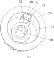
FIG. 2 is a schematic structural diagram (axial side view) of a button body and an internal structure of a flushing valve actuator according to the present disclosure; -
FIG. 3 is a schematic structural diagram (top view) of a button body and an internal structure of a flushing valve actuator according to the present disclosure; -
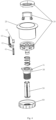
FIG. 4 is a schematic structural diagram (exploded view) of a flushing valve actuator according to the present disclosure; -
FIG. 5 is a schematic structural diagram (section view) of a linkage member of a flushing valve actuator of the present disclosure at a first position; -
FIG. 6 is a schematic structural diagram (section view) of a linkage member of a flushing valve actuator of the present disclosure at a second position; and -
FIG. 7 is a schematic structural diagram (section view) of a flushing valve actuator of the present disclosure when its button is pressed. - The reference signs in
FIGs. 1-7 respectively indicate: 10-button, 20-button body, 21-inner cavity, 30-thread member, 31-boss, 40-linkage member, 41-adjusting piece, 42-spring pin, 43-driving portion, 44-elastic member, 50-transmission rod, 60-thread member retaining cover. - To make the technical problem to be solved by the present disclosure, the technical solution and beneficial effects more comprehensible, the present disclosure will be further described in detail below with reference to the accompanying drawings and embodiments. It should be understood that the specific embodiments described herein are merely intended to explain the present disclosure, rather than to limit the present disclosure.
- Embodiment 1: a flushing valve actuator includes a switch body, a switch mounted in the switch body, a
thread member 30, and alinkage member 40 movable between a first position and a second position; when thelinkage member 40 is located at the first position, the switch body drives thethread member 30 to rotate through the linkage member, and the switch body is locked or unlocked through thethread member 30; when thelinkage member 40 is located at the second position, thelinkage member 40 disconnects the linkage between the switch body and thethread member 30, and the switch body cannot be locked or unlocked through thethread member 30. The flushing valve actuator of the present disclosure may be installed on a water tank, a toilet or the like that contains a drain valve. When the switch body is rotated forward, the switch body can be locked on the water tank or the toilet through thethread member 30, and when the switch body is rotated backward, the switch body can be unlocked from the water tank or the toilet through thethread member 30. - When the flushing valve actuator is assembled, the
linkage member 40 is placed at the first position first, and the switch body links thethread member 30 through thelinkage member 40. When the switch body is rotated, thethread member 30 is driven to rotate, thus locking the entire flushing valve actuator on the water tank, toilet or another device. After the installation is completed, thelinkage member 40 is adjusted to the second position. At this time, the linkage between the switch body and thethread member 30 is disconnected, and thethread member 30 cannot be driven to screw out of the installation position even if the switch body is rotated, thereby ensuring uneasy assembly of the flushing valve actuator. - Embodiment 2: referring to
FIG. 1 , on the basis of Embodiment 1, in this embodiment, thethread member 30 and the switch body are rotatably mounted together, and thelinkage member 40 is movably mounted on the switch body. It is easy to understand that thelinkage member 40 can also be movably mounted on thethread member 30. Specifically, the switch is abutton 10, thebutton 10 includes a button decorative piece, the switch body is abutton body 20, and thethread member 30 is a hollow structure open at both ends; atransmission rod 50 penetrates through thethread member 30, and one end of thetransmission rod 50 is connected to the switch. When thebutton 10 is pressed down, thebutton 10 drives thetransmission rod 50 to move downward, and the lower end of thetransmission rod 50 actuates an activation assembly (not shown) of the drain valve, thus opening the drain valve to drain water. The flushing valve actuator also includes a button elastic member. After an external force pressing thebutton 10 is removed, under the influence of the button elastic member, thebutton 10 drives thetransmission rod 50 to reset to initial positions together. - In this embodiment, the linkage member includes a
driving portion 43. When thebutton 10 is in an initial position, thebutton 10 covers thedriving portion 43; thebutton 10 leaves the initial position after being driven and exposes thedriving portion 43 for driving, so that the linkage member moves between the first position and the second position. - Refer to
FIG. 2 , aninner cavity 21 with a top opening is formed inside thebutton body 20, and the bottom of theinner cavity 21 is provided with a through hole. Both thebutton 10 and thelinkage member 40 are movably installed in theinner cavity 21, and thethread member 30 rotatably penetrates through the through hole and is capable of being axially limited. A linkage fitting member on thethread member 30 described below is located in theinner cavity 21, and a threaded portion on the threaded member is located outside thebutton body 20. - One end of the
thread member 30 extends through the through hole into theinner cavity 21 and is close to thelinkage member 40, and an end diameter of thethread member 30 at this end is greater than a diameter of the through hole to ensure that thethread member 30 will not fall off from the through hole. - A portion of the
thread member 30 located in theinner cavity 21 is provided with a linkage fitting portion, and thelinkage member 40 is provided with a corresponding linkage portion. When thelinkage member 40 is located at the first position, the linkage portion and the linkage fitting portion are in circumferential transmission fit; when thelinkage member 40 is located at the second position, the linkage portion is separated from the linkage fitting portion. Specifically, thelinkage member 40 moves between the first position and the second position along the axial direction of thethread member 30. When thethread member 30 is rotated, on a plane perpendicular to the axis of thethread member 30, a projection trajectory drawn by the linkage fitting portion partially overlaps with a projection of the linkage portion (referring toFIG. 3 ). When thelinkage member 40 is located at the first position, the linkage portion and the linkage fitting portion align in the axial direction of thethread member 30, and when thethread member 30 is rotated, the linkage portion abuts against the linkage fitting portion to form circumferential transmission fit. When thelinkage member 40 is located at the second position, the linkage portion and the linkage fitting portion misalign in the axial direction of thethread member 30, and thethread member 30 can rotate freely relative to thelinkage member 40. - In this embodiment, referring to
FIGs. 2 to 6 , thelinkage member 40 includes an adjustingpiece 41 and aspring pin 42, thespring pin 42 forms the linkage portion; a periphery of a portion of thethread member 30 located inside theinner cavity 21 of theswitch body 20 is provided with aboss 31, and theboss 31 forms the linkage fitting portion. The adjusting piece 41 is movably mounted inside a strip groove formed in an inner wall of the inner cavity 21, the length direction of the strip groove is parallel to the axis of the thread member 30, the spring pin 42 is elastically supported between the bottom of the adjusting piece 41 and the bottom wall of the inner cavity 21 through an elastic member 44, and the elastic member 44 is preferably a compression spring; the adjusting piece 41 and a side wall of the strip groove are respectively provided with a retaining protrusion and a retaining groove; when the linkage member 40 is located at the first position, the adjusting piece 41 is located at a position where the retaining protrusion and the retaining groove are separated from each other, the spring pin 42 and the boss 31 are in circumferential transmission fit under the influence of the elastic member 44; when the linkage member 40 is at the second position, the adjusting piece 41 is located at a position where the retaining protrusion and the retaining groove are in retaining fit, and the adjusting piece 41 overcomes the elastic force of the elastic member 44 so that the spring pin 42 and the boss 31 misalign in the axial direction of the thread member 30; and a driving portion 43 for manual or tool driving is disposed at a position of the adjusting piece 41 close to the button 10. Specifically, the drivingportion 43 is a toggle groove. During installation or assembly, a position of the adjustingpiece 41 is toggled by using the toggle groove, thereby changing the position of thespring pin 42 so that thespring pin 42 moves between positions corresponding to and misalign with theboss 31. Referring toFIGs. 5 and6 , when thebutton 10 is in an initial position, thebutton 10 covers the drivingportion 43 of thelinkage member 40; in order to toggle the adjustingpiece 41 in the switch body, thebutton 10 needs to be driven so that thebutton 10 leaves the initial position (as shown inFIG. 7 ), thereby exposing the drivingportion 43 of thelinkage member 40. In this way, as a position of thelinkage member 40 is hidden, a person who does not know the corresponding structure is unable to completely disassemble the flushing valve actuator. - The flushing valve actuator further includes a thread
member retaining cover 60. The bottom of the threadmember retaining cover 60 is provided with a thread hole corresponding to a thread of thethread member 30, and the threadmember retaining cover 60 is screwed into a portion of thethread member 30 extending out of the switch body, and thethread member 30 is rotatably mounted on the switch body through the threadmember retaining cover 60 and an end of thethread member 30 located in theinner cavity 21. - When the flushing valve actuator is assembled, the switch is placed to expose a driving portion of the adjusting
piece 41, and the adjustingpiece 41 is toggled upward so that the adjustingpiece 41 is located at a position where the retaining protrusion and the retaining groove are separated from each other. Thespring pin 42 moves upward under the influence of the elastic member to circumferentially transmission-fit with the boss 31 (referring toFIG. 5 ). At this time, thebutton body 20 is rotated to drive thethread member 30 through the adjustingpiece 41, thespring pin 42 and theboss 31, thus assembling or disassembling the flushing valve actuator, that is, locking or unlocking the drain switch. After the installation is complete, the adjustingpiece 41 is toggled downward so that the adjustingpiece 41 is located at a position where the retaining protrusion and the retaining groove are in retaining fit, and the adjustingpiece 41 overcomes the elastic force of the elastic member so that thespring pin 42 and theboss 31 misalign in the axial direction of the thread member 30 (referring toFIG. 6 ), thereby releasing a linkage relationship between thebutton body 20 and thethread member 30. - Embodiment 3: a flushing valve actuator with a clutch structure in the foregoing embodiment.
- It can be seen from the foregoing description of the present disclosure that, compared with the prior art, a flushing valve actuator comprising a clutch structure, and a flushing valve of the present disclosure both include a switch, a switch body, a thread member and a clutch structure comprising a linkage member with a linkage function; a connection relationship between the switch body and the thread member can be switched by changing a position of the linkage member; when the linkage member is located at a first position, the switch body and the thread member are in a linkage relationship, the thread member is driven by rotating the switch body, to lock or unlock the thread member, thereby realizing the locking or unlocking of the switch body; when the linkage member is at a second position so that the linkage relationship between the switch body and the thread member is disconnected, the switch body and the thread member are relatively independent of each other, that is, the switch body cannot be locked or unlocked through the thread member, and the installed thread member cannot be screwed out even if the switch body is rotated, ensuring that the entire drain valve switch cannot be easily removed and taken away.
Claims (11)
- A flushing valve actuator comprising a switch body (20), a switch (10) mounted in the switch body (20), a thread member (30), and a clutch structure comprising a linkage member (40), characterised in that in use the linkage member (40) is movable between a first position and a second position; when the linkage member (40) is located at the first position, the switch body (20) drives the thread member (30) to rotate through the linkage member (40), thus allowing locking or unlocking of the entire flushing valve actuator on an installation position of a water tank or another device; when the linkage member (40) is located at the second position, the linkage member (40) disconnects the linkage between the switch body (20) and the thread member (30), thus the thread member (30) cannot be driven to screw out of the installation position even if the switch body (20) is rotated.
- The flushing valve actuator according to claim 1, characterized in that the thread member (30) and the switch body (20) are rotatably mounted together, and the linkage member (40) is movably mounted on the switch body (20) or on the thread member (30).
- The flushing valve actuator according to claim 1, characterized in that the linkage member (40) comprises a driving portion (43), and when the switch (10) is located in an initial position, the switch (10) covers the driving portion (43); the switch (10) leaves the initial position after being driven and exposes the driving portion (43) for driving, so that the linkage member (40) moves between the first position and the second position.
- The flushing valve actuator according to any one of claims 1 to 3, characterized in that the thread member (30) is provided with a linkage fitting portion, and the linkage member (40) is provided with a corresponding linkage portion; when the linkage member (40) is located at the first position, the linkage portion and the linkage fitting portion are in circumferential transmission fit; when the linkage member (40) is located at the second position, the linkage portion is separated from the linkage fitting portion.
- The flushing valve actuator according to claim 4, characterized in that the switch (10) is a button, and the switch body (20) is a button body; an inner cavity (21) with a top opening is formed inside the button body (20), and a bottom of the inner cavity is provided with a through hole; both the button (10) and the linkage member (40) are movably installed in the inner cavity (21), and the thread member (30) rotatably penetrates through the through hole and is capable of being axially limited, and the linkage fitting portion on the thread member (30) is located in the inner cavity (21), and a thread portion on the thread member (30) is located outside the button body (20).
- The flushing valve actuator according to claim 4, characterized in that the linkage member (40) moves between the first position and the second position along an axial direction of the thread member (30); when the thread member (30) is rotated, on a plane perpendicular to an axis of the thread member (30), a projection trajectory drawn by the linkage fitting portion partially overlaps with a projection of the linkage portion; when the linkage member (40) is located at the first position, the linkage portion and the linkage fitting portion align in the axial direction of the thread member (30), and when the switch body (20) is rotated, the linkage portion abuts against the linkage fitting portion to form circumferential transmission fit; when the linkage member (40) is located at the second position, the linkage portion and the linkage fitting portion misalign in the axial direction of the thread member (30), and the thread member (30) is able to rotate freely relative to the linkage member (40).
- The flushing valve actuator according to claim 5, characterized in that the linkage member (40) comprises an adjusting piece (41) and a spring pin (42), and the spring pin (42) forms the linkage portion; a periphery of a portion of the thread member (30) located inside the switch body (20) is provided with a boss (31), and the boss (31) forms the linkage fitting portion.
- The flushing valve actuator according to claim 7, characterized in that the adjusting piece (41) is movably mounted inside a strip groove formed in the switch body (20), and a length direction of the strip groove is parallel to the axis of the thread member (30), the spring pin (42) is elastically supported between the adjusting piece (41) and the switch body (20) through an elastic member (44); the adjusting piece (41) and a side wall of the strip groove are respectively provided with a retaining protrusion and a retaining groove; when the linkage member (40) is located at the first position, the adjusting piece (41) is located at a position where the retaining protrusion and the retaining groove are separated from each other, and the spring pin (42) and the boss (31) are in circumferential transmission fit under the influence of the elastic member (44), when the linkage member (40) is located at the second position, the adjusting piece (41) is located at a position where the retaining protrusion and the retaining groove are in retaining fit, and the adjusting piece overcomes the elastic force of the elastic member so that the spring pin (42) and the boss (31) misalign in the axial direction of the thread member (30); and a driving portion (43) for manual or tool driving is disposed on a position of the adjusting piece (41) close to the button.
- The flushing valve actuator according to claim 5, characterized in that the thread member (30) has an end located in the inner cavity (21) and having an end diameter greater than a diameter of the through hole; and the drain valve switch further comprises a thread member retaining cover (60), wherein the thread member retaining cover (60) is provided with a thread hole corresponding to a thread of the thread member (30), the thread member retaining cover (60) is screwed into a portion of the thread member (30) extending out of the switch body (20), and the thread member (30) is relatively rotatably mounted on the switch body (20) through the thread member retaining cover (60) and the end of the thread member (30) located in the inner cavity (21).
- The flushing valve actuator according to claim 1, characterized in that the thread member (30) is a hollow structure open at both ends; a transmission rod (50) penetrates through the thread member (30) and has an end connected to the switch (10).
- A flushing valve, comprising the flushing valve actuator according to any one of claims 1 to 10.
Applications Claiming Priority (2)
| Application Number | Priority Date | Filing Date | Title |
|---|---|---|---|
| CN201920214862.2U CN210066925U (en) | 2019-02-20 | 2019-02-20 | Take separation and reunion structure's drainage valve switch and drain valve |
| PCT/CN2020/075634 WO2020169007A1 (en) | 2019-02-20 | 2020-02-18 | Drain valve switch having clutch structure, and drain valve |
Publications (4)
| Publication Number | Publication Date |
|---|---|
| EP3929366A1 EP3929366A1 (en) | 2021-12-29 |
| EP3929366A4 EP3929366A4 (en) | 2022-03-30 |
| EP3929366C0 EP3929366C0 (en) | 2025-04-02 |
| EP3929366B1 true EP3929366B1 (en) | 2025-04-02 |
Family
ID=69432628
Family Applications (1)
| Application Number | Title | Priority Date | Filing Date |
|---|---|---|---|
| EP20758677.7A Active EP3929366B1 (en) | 2019-02-20 | 2020-02-18 | Drain valve switch having clutch structure, and drain valve |
Country Status (6)
| Country | Link |
|---|---|
| EP (1) | EP3929366B1 (en) |
| CN (1) | CN210066925U (en) |
| ES (1) | ES3025658T3 (en) |
| MA (1) | MA55035A (en) |
| PL (1) | PL3929366T3 (en) |
| WO (1) | WO2020169007A1 (en) |
Families Citing this family (2)
| Publication number | Priority date | Publication date | Assignee | Title |
|---|---|---|---|---|
| CN210066925U (en) * | 2019-02-20 | 2020-02-14 | 厦门瑞尔特卫浴科技股份有限公司 | Take separation and reunion structure's drainage valve switch and drain valve |
| CN116220160B (en) * | 2023-03-14 | 2025-07-01 | 箭牌家居集团股份有限公司 | Knob devices and water equipment |
Family Cites Families (10)
| Publication number | Priority date | Publication date | Assignee | Title |
|---|---|---|---|---|
| ES2117903B1 (en) * | 1992-11-12 | 1999-03-16 | Agullo Pablo Fominaya | IMPROVEMENTS INTRODUCED IN THE PATENT OF INVENTION NO. P-9202287/1, FOR: IMPROVEMENTS IN TOILET UNLOADERS FOR TOILETS. |
| KR20110003864U (en) * | 2009-10-13 | 2011-04-20 | 주식회사 루트싸이언스 | Toilet Bowl Drain Valve |
| EP2746472B1 (en) * | 2012-12-18 | 2015-09-16 | Geberit International AG | Actuation device for a discharge fitting |
| CN205189086U (en) * | 2015-12-04 | 2016-04-27 | 厦门立业卫浴工业有限公司 | General exchange device of drain valve key -holder |
| CN206080379U (en) * | 2016-06-28 | 2017-04-12 | 厦门康谱卫浴科技有限公司 | Luminous flush tank button of intelligence |
| CN106195295B (en) * | 2016-08-29 | 2018-08-28 | 张玉莲 | Clutch structure |
| CN206512804U (en) * | 2017-02-24 | 2017-09-22 | 九牧厨卫股份有限公司 | Quick disassembly device for drain valve and drain valve |
| CN107237911B (en) * | 2017-06-23 | 2023-08-18 | 厦门瑞尔特卫浴科技股份有限公司 | Connection structure of drain valve |
| CN207109967U (en) * | 2017-07-18 | 2018-03-16 | 厦门瑞尔特卫浴科技股份有限公司 | A kind of attachment structure of draining valve |
| CN210066925U (en) * | 2019-02-20 | 2020-02-14 | 厦门瑞尔特卫浴科技股份有限公司 | Take separation and reunion structure's drainage valve switch and drain valve |
-
2019
- 2019-02-20 CN CN201920214862.2U patent/CN210066925U/en active Active
-
2020
- 2020-02-18 ES ES20758677T patent/ES3025658T3/en active Active
- 2020-02-18 PL PL20758677.7T patent/PL3929366T3/en unknown
- 2020-02-18 MA MA055035A patent/MA55035A/en unknown
- 2020-02-18 EP EP20758677.7A patent/EP3929366B1/en active Active
- 2020-02-18 WO PCT/CN2020/075634 patent/WO2020169007A1/en not_active Ceased
Also Published As
| Publication number | Publication date |
|---|---|
| CN210066925U (en) | 2020-02-14 |
| EP3929366A4 (en) | 2022-03-30 |
| WO2020169007A1 (en) | 2020-08-27 |
| PL3929366T3 (en) | 2025-08-11 |
| MA55035A (en) | 2022-03-30 |
| ES3025658T3 (en) | 2025-06-09 |
| EP3929366C0 (en) | 2025-04-02 |
| EP3929366A1 (en) | 2021-12-29 |
Similar Documents
| Publication | Publication Date | Title |
|---|---|---|
| US4052092A (en) | Latch operating device including operating and latch connection improvements | |
| US9816258B2 (en) | Drain control assembly | |
| US9982455B2 (en) | Side mounted privacy lock for a residential door | |
| US9032560B2 (en) | Multi-flush mode toilet | |
| JPH0796864B2 (en) | Latch structure for mounting in doors and the like | |
| US8382621B2 (en) | Electrical drive apparatus for valves | |
| EP3929366A1 (en) | Drain valve switch having clutch structure, and drain valve | |
| US20110099711A1 (en) | Driving construction for driving washbasin, Bidet, kitchen sink, bath tub, shower draining systems | |
| EP3804594A1 (en) | Rotary control quick-dismounting hinge and toilet cover plate having same | |
| RU2406905C2 (en) | System of manual and automatic drive for valve and complete set to it | |
| KR101759733B1 (en) | A body for using push and pull door lock | |
| CN214999735U (en) | Valve switch boosters and valve assemblies | |
| JP2560776Y2 (en) | Operation part structure of drain tank for water tank | |
| CN103210156A (en) | Toilet trip lever assembly | |
| CN2916293Y (en) | Valve with coded lock | |
| KR200196289Y1 (en) | Electromotion ball valve | |
| KR20180032858A (en) | Actuators for disk valve | |
| JP3089656U (en) | Improved lock structure | |
| KR200393331Y1 (en) | A driver for a electric valve using cooling and heating pipe | |
| JP7813055B2 (en) | Water stop valve opening and closing device | |
| JP2005299766A (en) | Valve device with lock mechanism | |
| CN111623165B (en) | Waterway control box and shower | |
| CN216689624U (en) | Water inlet fitting quick assembly disassembly device of water tank | |
| KR101697047B1 (en) | Valve driver | |
| JP3481332B2 (en) | Manual operation unit mounting structure |
Legal Events
| Date | Code | Title | Description |
|---|---|---|---|
| STAA | Information on the status of an ep patent application or granted ep patent |
Free format text: STATUS: THE INTERNATIONAL PUBLICATION HAS BEEN MADE |
|
| PUAI | Public reference made under article 153(3) epc to a published international application that has entered the european phase |
Free format text: ORIGINAL CODE: 0009012 |
|
| STAA | Information on the status of an ep patent application or granted ep patent |
Free format text: STATUS: REQUEST FOR EXAMINATION WAS MADE |
|
| 17P | Request for examination filed |
Effective date: 20210920 |
|
| AK | Designated contracting states |
Kind code of ref document: A1 Designated state(s): AL AT BE BG CH CY CZ DE DK EE ES FI FR GB GR HR HU IE IS IT LI LT LU LV MC MK MT NL NO PL PT RO RS SE SI SK SM TR |
|
| RIN1 | Information on inventor provided before grant (corrected) |
Inventor name: ZHANG, RONGYU Inventor name: HONG, QICHENG Inventor name: WANG, XINGDONG |
|
| A4 | Supplementary search report drawn up and despatched |
Effective date: 20220225 |
|
| RIC1 | Information provided on ipc code assigned before grant |
Ipc: E03D 1/34 20060101ALN20220221BHEP Ipc: E03D 5/09 20060101ALI20220221BHEP Ipc: G05G 1/02 20060101ALI20220221BHEP Ipc: F16K 31/44 20060101ALI20220221BHEP Ipc: E03D 5/02 20060101AFI20220221BHEP |
|
| DAX | Request for extension of the european patent (deleted) | ||
| RAV | Requested validation state of the european patent: fee paid |
Extension state: MA Effective date: 20210920 |
|
| REG | Reference to a national code |
Ref country code: DE Ref legal event code: R079 Free format text: PREVIOUS MAIN CLASS: E03D0001340000 Ipc: E03D0005020000 Ref country code: DE Ref legal event code: R079 Ref document number: 602020048748 Country of ref document: DE Free format text: PREVIOUS MAIN CLASS: E03D0001340000 Ipc: E03D0005020000 |
|
| GRAP | Despatch of communication of intention to grant a patent |
Free format text: ORIGINAL CODE: EPIDOSNIGR1 |
|
| STAA | Information on the status of an ep patent application or granted ep patent |
Free format text: STATUS: GRANT OF PATENT IS INTENDED |
|
| RIC1 | Information provided on ipc code assigned before grant |
Ipc: E03D 1/34 20060101ALN20240919BHEP Ipc: E03D 5/09 20060101ALI20240919BHEP Ipc: G05G 1/02 20060101ALI20240919BHEP Ipc: F16K 31/44 20060101ALI20240919BHEP Ipc: E03D 5/02 20060101AFI20240919BHEP |
|
| INTG | Intention to grant announced |
Effective date: 20241011 |
|
| GRAS | Grant fee paid |
Free format text: ORIGINAL CODE: EPIDOSNIGR3 |
|
| GRAA | (expected) grant |
Free format text: ORIGINAL CODE: 0009210 |
|
| STAA | Information on the status of an ep patent application or granted ep patent |
Free format text: STATUS: THE PATENT HAS BEEN GRANTED |
|
| AK | Designated contracting states |
Kind code of ref document: B1 Designated state(s): AL AT BE BG CH CY CZ DE DK EE ES FI FR GB GR HR HU IE IS IT LI LT LU LV MC MK MT NL NO PL PT RO RS SE SI SK SM TR |
|
| REG | Reference to a national code |
Ref country code: GB Ref legal event code: FG4D |
|
| REG | Reference to a national code |
Ref country code: CH Ref legal event code: EP |
|
| REG | Reference to a national code |
Ref country code: IE Ref legal event code: FG4D |
|
| REG | Reference to a national code |
Ref country code: DE Ref legal event code: R096 Ref document number: 602020048748 Country of ref document: DE |
|
| REG | Reference to a national code |
Ref country code: ES Ref legal event code: FG2A Ref document number: 3025658 Country of ref document: ES Kind code of ref document: T3 Effective date: 20250609 |
|
| U01 | Request for unitary effect filed |
Effective date: 20250430 |
|
| U07 | Unitary effect registered |
Designated state(s): AT BE BG DE DK EE FI FR IT LT LU LV MT NL PT RO SE SI Effective date: 20250508 |
|
| PG25 | Lapsed in a contracting state [announced via postgrant information from national office to epo] |
Ref country code: GR Free format text: LAPSE BECAUSE OF FAILURE TO SUBMIT A TRANSLATION OF THE DESCRIPTION OR TO PAY THE FEE WITHIN THE PRESCRIBED TIME-LIMIT Effective date: 20250703 Ref country code: NO Free format text: LAPSE BECAUSE OF FAILURE TO SUBMIT A TRANSLATION OF THE DESCRIPTION OR TO PAY THE FEE WITHIN THE PRESCRIBED TIME-LIMIT Effective date: 20250702 |
|
| PG25 | Lapsed in a contracting state [announced via postgrant information from national office to epo] |
Ref country code: HR Free format text: LAPSE BECAUSE OF FAILURE TO SUBMIT A TRANSLATION OF THE DESCRIPTION OR TO PAY THE FEE WITHIN THE PRESCRIBED TIME-LIMIT Effective date: 20250402 |
|
| PG25 | Lapsed in a contracting state [announced via postgrant information from national office to epo] |
Ref country code: RS Free format text: LAPSE BECAUSE OF FAILURE TO SUBMIT A TRANSLATION OF THE DESCRIPTION OR TO PAY THE FEE WITHIN THE PRESCRIBED TIME-LIMIT Effective date: 20250702 |
|
| PG25 | Lapsed in a contracting state [announced via postgrant information from national office to epo] |
Ref country code: IS Free format text: LAPSE BECAUSE OF FAILURE TO SUBMIT A TRANSLATION OF THE DESCRIPTION OR TO PAY THE FEE WITHIN THE PRESCRIBED TIME-LIMIT Effective date: 20250802 |
|
| PG25 | Lapsed in a contracting state [announced via postgrant information from national office to epo] |
Ref country code: SM Free format text: LAPSE BECAUSE OF FAILURE TO SUBMIT A TRANSLATION OF THE DESCRIPTION OR TO PAY THE FEE WITHIN THE PRESCRIBED TIME-LIMIT Effective date: 20250402 |
|
| PG25 | Lapsed in a contracting state [announced via postgrant information from national office to epo] |
Ref country code: SK Free format text: LAPSE BECAUSE OF FAILURE TO SUBMIT A TRANSLATION OF THE DESCRIPTION OR TO PAY THE FEE WITHIN THE PRESCRIBED TIME-LIMIT Effective date: 20250402 |
|
| PLBE | No opposition filed within time limit |
Free format text: ORIGINAL CODE: 0009261 |
|
| STAA | Information on the status of an ep patent application or granted ep patent |
Free format text: STATUS: NO OPPOSITION FILED WITHIN TIME LIMIT |
|
| REG | Reference to a national code |
Ref country code: CH Ref legal event code: L10 Free format text: ST27 STATUS EVENT CODE: U-0-0-L10-L00 (AS PROVIDED BY THE NATIONAL OFFICE) Effective date: 20260211 |
|
| 26N | No opposition filed |
Effective date: 20260105 |
|
| U20 | Renewal fee for the european patent with unitary effect paid |
Year of fee payment: 7 Effective date: 20260212 |
|
| PGFP | Annual fee paid to national office [announced via postgrant information from national office to epo] |
Ref country code: GB Payment date: 20260213 Year of fee payment: 7 |
|
| PGFP | Annual fee paid to national office [announced via postgrant information from national office to epo] |
Ref country code: ES Payment date: 20260305 Year of fee payment: 7 |
|
| VS25 | Lapsed in a validation state [announced via postgrant information from nat. office to epo] |
Ref country code: MA Free format text: LAPSE BECAUSE OF FAILURE TO SUBMIT A TRANSLATION OF THE DESCRIPTION OR TO PAY THE FEE WITHIN THE PRESCRIBED TIME-LIMIT Effective date: 20250402 |
|
| PGFP | Annual fee paid to national office [announced via postgrant information from national office to epo] |
Ref country code: TR Payment date: 20260209 Year of fee payment: 7 |
|
| PGFP | Annual fee paid to national office [announced via postgrant information from national office to epo] |
Ref country code: PL Payment date: 20260215 Year of fee payment: 7 |
|
| PGFP | Annual fee paid to national office [announced via postgrant information from national office to epo] |
Ref country code: CZ Payment date: 20260430 Year of fee payment: 7 |