EP3929385A1 - Chariot pour une porte coulissante - Google Patents
Chariot pour une porte coulissante Download PDFInfo
- Publication number
- EP3929385A1 EP3929385A1 EP21174981.7A EP21174981A EP3929385A1 EP 3929385 A1 EP3929385 A1 EP 3929385A1 EP 21174981 A EP21174981 A EP 21174981A EP 3929385 A1 EP3929385 A1 EP 3929385A1
- Authority
- EP
- European Patent Office
- Prior art keywords
- control element
- strip
- support part
- roller holder
- trolley according
- Prior art date
- Legal status (The legal status is an assumption and is not a legal conclusion. Google has not performed a legal analysis and makes no representation as to the accuracy of the status listed.)
- Granted
Links
Images


Classifications
-
- E—FIXED CONSTRUCTIONS
- E05—LOCKS; KEYS; WINDOW OR DOOR FITTINGS; SAFES
- E05D—HINGES OR SUSPENSION DEVICES FOR DOORS, WINDOWS OR WINGS
- E05D15/00—Suspension arrangements for wings
- E05D15/56—Suspension arrangements for wings with successive different movements
- E05D15/565—Suspension arrangements for wings with successive different movements for raising wings before sliding
-
- E—FIXED CONSTRUCTIONS
- E05—LOCKS; KEYS; WINDOW OR DOOR FITTINGS; SAFES
- E05Y—INDEXING SCHEME ASSOCIATED WITH SUBCLASSES E05D AND E05F, RELATING TO CONSTRUCTION ELEMENTS, ELECTRIC CONTROL, POWER SUPPLY, POWER SIGNAL OR TRANSMISSION, USER INTERFACES, MOUNTING OR COUPLING, DETAILS, ACCESSORIES, AUXILIARY OPERATIONS NOT OTHERWISE PROVIDED FOR, APPLICATION THEREOF
- E05Y2201/00—Constructional elements; Accessories therefor
- E05Y2201/60—Suspension or transmission members; Accessories therefor
- E05Y2201/622—Suspension or transmission members elements
- E05Y2201/638—Cams; Ramps
-
- E—FIXED CONSTRUCTIONS
- E05—LOCKS; KEYS; WINDOW OR DOOR FITTINGS; SAFES
- E05Y—INDEXING SCHEME ASSOCIATED WITH SUBCLASSES E05D AND E05F, RELATING TO CONSTRUCTION ELEMENTS, ELECTRIC CONTROL, POWER SUPPLY, POWER SIGNAL OR TRANSMISSION, USER INTERFACES, MOUNTING OR COUPLING, DETAILS, ACCESSORIES, AUXILIARY OPERATIONS NOT OTHERWISE PROVIDED FOR, APPLICATION THEREOF
- E05Y2201/00—Constructional elements; Accessories therefor
- E05Y2201/60—Suspension or transmission members; Accessories therefor
- E05Y2201/622—Suspension or transmission members elements
- E05Y2201/682—Pins
-
- E—FIXED CONSTRUCTIONS
- E05—LOCKS; KEYS; WINDOW OR DOOR FITTINGS; SAFES
- E05Y—INDEXING SCHEME ASSOCIATED WITH SUBCLASSES E05D AND E05F, RELATING TO CONSTRUCTION ELEMENTS, ELECTRIC CONTROL, POWER SUPPLY, POWER SIGNAL OR TRANSMISSION, USER INTERFACES, MOUNTING OR COUPLING, DETAILS, ACCESSORIES, AUXILIARY OPERATIONS NOT OTHERWISE PROVIDED FOR, APPLICATION THEREOF
- E05Y2800/00—Details, accessories and auxiliary operations not otherwise provided for
-
- E—FIXED CONSTRUCTIONS
- E05—LOCKS; KEYS; WINDOW OR DOOR FITTINGS; SAFES
- E05Y—INDEXING SCHEME ASSOCIATED WITH SUBCLASSES E05D AND E05F, RELATING TO CONSTRUCTION ELEMENTS, ELECTRIC CONTROL, POWER SUPPLY, POWER SIGNAL OR TRANSMISSION, USER INTERFACES, MOUNTING OR COUPLING, DETAILS, ACCESSORIES, AUXILIARY OPERATIONS NOT OTHERWISE PROVIDED FOR, APPLICATION THEREOF
- E05Y2800/00—Details, accessories and auxiliary operations not otherwise provided for
- E05Y2800/26—Form or shape
- E05Y2800/292—Form or shape having apertures
- E05Y2800/296—Slots
-
- E—FIXED CONSTRUCTIONS
- E05—LOCKS; KEYS; WINDOW OR DOOR FITTINGS; SAFES
- E05Y—INDEXING SCHEME ASSOCIATED WITH SUBCLASSES E05D AND E05F, RELATING TO CONSTRUCTION ELEMENTS, ELECTRIC CONTROL, POWER SUPPLY, POWER SIGNAL OR TRANSMISSION, USER INTERFACES, MOUNTING OR COUPLING, DETAILS, ACCESSORIES, AUXILIARY OPERATIONS NOT OTHERWISE PROVIDED FOR, APPLICATION THEREOF
- E05Y2900/00—Application of doors, windows, wings or fittings thereof
- E05Y2900/10—Application of doors, windows, wings or fittings thereof for buildings or parts thereof
- E05Y2900/13—Type of wing
- E05Y2900/132—Doors
Definitions
- the present invention relates to a carriage for a sliding door, in particular a lift-and-slide door, with a roller holder on which at least one roller is rotatably mounted and can be moved along a running rail, a support part on which a door leaf can be supported and fixed, a lifting device for raising and lowering the support part relative to the roll holder, and a corner deflection with a rotatably mounted bell bracket that can be moved via a drive rod.
- the EP 3 064 683 B1 discloses a carriage arrangement for a lift-slide door, in which a support part can be moved relative to a roller holder with rollers via a lifting device.
- a curved guide is formed in the support part through which a bolt penetrates, which can be moved via a control element which is connected to a corner deflection via a chain link.
- the corner deflection can be rotated with the bell angle via a drive rod, so that the roller holder is then moved relative to the support part via the chain link and the control element.
- a similar drive mechanism is shown in DE 10 2020 111 221 , wherein here the control element is connected to a roller holder of a first carriage, which is coupled via a connecting rod to a roller holder of a second carriage in order to raise or lower the support parts on the two carriages.
- a lifting device for raising and lowering the support part relative to the roller holder is driven via a corner deflection with a rotatable bell-shaped bracket, which can be moved via a drive rod, with at least one strip-shaped control element being articulated on the bell-shaped bracket, which is connected to the lifting device connected is.
- the strip-shaped control element is directly connected to the bell angle in an articulated manner, so that there is no intermediate link, which reduces the number of components.
- the operating forces can be reduced, since the articulation point of the control element can be designed to be optimized in order to achieve a homogeneous lifting movement when the lifting device is actuated.
- the at least one control element is preferably connected to the lifting device in an articulated manner, so that the control element can be pivoted when the bell angle is rotated.
- a curved guide is provided on the support part, on which a guide part is movably arranged.
- the guide part can be fixed to the roll holder so that the guide part can be moved together with the roll holder via the at least one strip-shaped control element.
- the guide part is preferably designed as a bolt which passes through the roller holder and the curved guide and is connected to a control element at the ends protruding from the roller holder.
- Two strip-shaped control elements are thus preferably provided, which are connected to the guide part on opposite sides, so that an essentially symmetrical introduction of force into the guide part is ensured.
- the guide part can be designed as a rotatable bolt so that the two strip-shaped control elements can be rotated together with the bolt or around the bolt.
- Each strip-shaped control part is preferably designed in one piece, in particular from a bent sheet metal or a plastic.
- the bell angle is preferably rotatably mounted on the support part, two tabs on the support part preferably being bent over to form an axis of rotation, and a portion of the bell angle engaging between the two tabs.
- each strip-shaped control element has a step so that the end of the control element articulated on the bell bracket is arranged in a different plane than the end of the control element arranged on the roller holder.
- the two ends of the two control elements on the bell angle are preferably arranged at a smaller distance than the two ends of the control element on the roller holder, so that there is a compact structure in the area of the corner deflection.
- the at least one strip-shaped control element can have an opening, recess or receptacle in which one end of an axle for rotatably mounting a roller on the roller holder is received.
- the roller holder preferably comprises two rotatably mounted rollers, the roller being rotatably mounted on the side facing the corner deflection on an axis which engages in the opening, recess or receptacle.
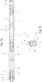
- a carriage 1 for a lift and slide door comprises a roller holder 2, which comprises two spaced webs, between which two rollers 3 are arranged, each of which is held on an axis 9.
- a support part 5 is provided on the roll holder 2, on which a door leaf can be supported and fixed.
- the support part 5 can be raised and lowered via a lifting device 6, with FIG Figure 1 the lowered position of the support part 5 is shown, in which the support part 5 rests on a running rail 4 or a floor, and in FIG Figure 2 a raised position of the support part 5 is shown, in which the carriage with the rollers 3 can be moved along the running rail 4.
- the support part 5 has a curved guide 8 which is designed as a slot which is aligned inclined to the horizontal.
- In the curve guide 8 there is a guide part 7 in the form of a bolt which passes through the curve guide 8 and the roller holder 2.
- the two protruding ends of the guide part 7 are connected to a strip-shaped control element 18.
- a corner deflection 10 which has a rotatably mounted bell bracket 11.
- the bell angle 11 is designed as a rotating part which can be rotated about an axis of rotation 12 and comprises two spaced articulation points 16 and 17.
- a first articulation point 16 is articulated to a drive rod 13 which can be moved via an actuating gear, as shown in FIG EP 3 064 683 B1 is shown.
- the second articulation point 17 of the bell angle 11 is connected in an articulated manner to one end 21 of the strip-shaped control element 18.
- the support part 5 is formed angularly and comprises a vertically upwardly projecting web 15 which can be fixed to a vertical frame spar of a door leaf.
- the strip-shaped control element 18 can be produced in one piece from a bent sheet metal or from plastic and comprises a plate-shaped section on the end 22 facing away from the bell angle 11, the end of which is connected to the guide part 7.
- a step 20 is provided between the end 22 and the end 21, which is inclined to the two ends 21 and 22 so that the ends 21 and 22 are arranged in different planes.
- the roller holder 2 can be connected to a connecting rod via a coupling element 23 in order to connect a second carriage to the carriage shown, as shown in FIG DE 10 2020 111 221 is revealed.
- a seal or brush 24 is also provided on the side facing the floor in order to remove impurities from the running rail 4 when the carriage 1 is moved in the closing direction.
- the bell bracket 11 can be rotated about the axis of rotation 12 via the drive rod 13, so that the strip-shaped control element 18 is moved so that the guide part 7 is displaced along the curved guide 8, which the support part 5 relative to the roller holder 2 raises.
- the strip-shaped control element 18 pivots about the axis of the guide part 7.
- an opening 19 is also recessed, in which one end of the axis 9 for mounting the roller 3 is received.
- the overall width of the carriage 1 can be kept small through the opening 19.
- a strip-shaped control element 18 is arranged on opposite sides of the roll holder 2 formed from two webs, which control element encompasses the roll holder 2.
- the two control elements 18 form a step 20 at a distance from the roller holder 2, so that the ends 21 of the two control elements 18 are arranged closer to one another than the ends 22 around the roller holder 2.
- the two ends 21 are articulated to the bell angle via the pivot point 17 11 connected, which is substantially T-shaped.
- FIG 3B the area of the guide part 7 is shown in section, which extends through the curved guide on the support part 5 and the two webs of the roller holder 2, the protruding ends of the guide part 7 being connected to a strip-shaped control element 18 each.
Landscapes
- Engineering & Computer Science (AREA)
- Mechanical Engineering (AREA)
- Power-Operated Mechanisms For Wings (AREA)
Applications Claiming Priority (1)
| Application Number | Priority Date | Filing Date | Title |
|---|---|---|---|
| DE102020116461.0A DE102020116461A1 (de) | 2020-06-23 | 2020-06-23 | Laufwagen für eine Schiebetür |
Publications (2)
| Publication Number | Publication Date |
|---|---|
| EP3929385A1 true EP3929385A1 (fr) | 2021-12-29 |
| EP3929385B1 EP3929385B1 (fr) | 2024-01-10 |
Family
ID=76034525
Family Applications (1)
| Application Number | Title | Priority Date | Filing Date |
|---|---|---|---|
| EP21174981.7A Active EP3929385B1 (fr) | 2020-06-23 | 2021-05-20 | Chariot pour une porte coulissante |
Country Status (3)
| Country | Link |
|---|---|
| EP (1) | EP3929385B1 (fr) |
| DE (1) | DE102020116461A1 (fr) |
| PL (1) | PL3929385T3 (fr) |
Cited By (1)
| Publication number | Priority date | Publication date | Assignee | Title |
|---|---|---|---|---|
| WO2025045421A1 (fr) * | 2023-08-31 | 2025-03-06 | Maco Technologie Gmbh | Ensemble bogie avec aide au montage pour fixer un élément de levage/coulissement |
Citations (5)
| Publication number | Priority date | Publication date | Assignee | Title |
|---|---|---|---|---|
| EP1298272A2 (fr) * | 2001-09-27 | 2003-04-02 | Gretsch-Unitas GmbH Baubeschläge | Chariot d'une ferrure pour portes ou fenêtres à soulèvement et coulissement et ferrure avec un tel chariot |
| KR20050007212A (ko) * | 2004-11-12 | 2005-01-17 | 에이스이노텍 주식회사 | 창호 승강장치 |
| EP2712993A1 (fr) * | 2012-09-26 | 2014-04-02 | GSG INTERNATIONAL S.p.A. | Unité de chariot pour porte ou fenêtre coulissante du type levant et coulissant |
| EP2712994B1 (fr) * | 2012-09-26 | 2017-02-01 | GSG INTERNATIONAL S.p.A. | Unité de chariot pour porte ou fenêtre coulissante du type levant et coulissant |
| EP3064683B1 (fr) | 2015-03-02 | 2017-09-20 | HAUTAU GmbH | Systeme de chariot pour porte coulissante |
Family Cites Families (1)
| Publication number | Priority date | Publication date | Assignee | Title |
|---|---|---|---|---|
| DE102020111221A1 (de) | 2020-04-24 | 2021-10-28 | Hautau Gmbh | Laufwagenanordnung für eine Schiebetür |
-
2020
- 2020-06-23 DE DE102020116461.0A patent/DE102020116461A1/de not_active Withdrawn
-
2021
- 2021-05-20 EP EP21174981.7A patent/EP3929385B1/fr active Active
- 2021-05-20 PL PL21174981.7T patent/PL3929385T3/pl unknown
Patent Citations (5)
| Publication number | Priority date | Publication date | Assignee | Title |
|---|---|---|---|---|
| EP1298272A2 (fr) * | 2001-09-27 | 2003-04-02 | Gretsch-Unitas GmbH Baubeschläge | Chariot d'une ferrure pour portes ou fenêtres à soulèvement et coulissement et ferrure avec un tel chariot |
| KR20050007212A (ko) * | 2004-11-12 | 2005-01-17 | 에이스이노텍 주식회사 | 창호 승강장치 |
| EP2712993A1 (fr) * | 2012-09-26 | 2014-04-02 | GSG INTERNATIONAL S.p.A. | Unité de chariot pour porte ou fenêtre coulissante du type levant et coulissant |
| EP2712994B1 (fr) * | 2012-09-26 | 2017-02-01 | GSG INTERNATIONAL S.p.A. | Unité de chariot pour porte ou fenêtre coulissante du type levant et coulissant |
| EP3064683B1 (fr) | 2015-03-02 | 2017-09-20 | HAUTAU GmbH | Systeme de chariot pour porte coulissante |
Cited By (1)
| Publication number | Priority date | Publication date | Assignee | Title |
|---|---|---|---|---|
| WO2025045421A1 (fr) * | 2023-08-31 | 2025-03-06 | Maco Technologie Gmbh | Ensemble bogie avec aide au montage pour fixer un élément de levage/coulissement |
Also Published As
| Publication number | Publication date |
|---|---|
| PL3929385T3 (pl) | 2024-05-20 |
| EP3929385B1 (fr) | 2024-01-10 |
| DE102020116461A1 (de) | 2021-12-23 |
Similar Documents
| Publication | Publication Date | Title |
|---|---|---|
| DE2648344B2 (de) | Beschlag für Schiebefenster, Schiebetüren o.dgl. | |
| EP0983196A1 (fr) | Vehicule de remorquage pour avions | |
| EP1092074A1 (fr) | Porte articulee au plafond pour hauteurs de chute particulierement faibles | |
| EP3064683B1 (fr) | Systeme de chariot pour porte coulissante | |
| DE3405994C2 (de) | Seilzug-Fensterheber | |
| EP3929385B1 (fr) | Chariot pour une porte coulissante | |
| EP3901402B1 (fr) | Agencement de chariot pour une porte coulissante | |
| DE2643854A1 (de) | Seitenwand | |
| WO2016023738A1 (fr) | Système de chariots pour portes ou fenêtres relevables coulissantes | |
| DE19731932C2 (de) | Deckengliedertor für besonders niedrige Sturzhöhen | |
| EP1034999B1 (fr) | Wagon de marchandises avec paroi coulissante | |
| EP2267257B1 (fr) | Dispositif de blocage | |
| DE202007014472U1 (de) | Türkonstruktion für einen Aufzug | |
| DE2347916A1 (de) | Antriebsvorrichtung zum gleichzeitigen anheben von tueren an einem aufzug | |
| DE102021201885A1 (de) | Andruckeinrichtung für ein Fenster oder eine Tür | |
| EP0805252A2 (fr) | Lève-vitre à câble à course agrandie | |
| EP4174268B1 (fr) | Ferrure roulante de porte coulissante et agencement de porte coulissante associé | |
| EP4091970B1 (fr) | Dispositif de levage de charges | |
| DE29701732U1 (de) | Scherenhubtisch | |
| EP1798361B1 (fr) | Porte | |
| WO1997032106A1 (fr) | Chariot transporteur de charges pour un monte-charge incline | |
| DE102005024289A1 (de) | Scherenhubtisch | |
| EP1034998B1 (fr) | Dispositif supérieur de deplacement pour parois coulissantes | |
| DE1559725C (de) | Hebebeschlag für den Flügelrahmen eines Schiebefensters oder einer Schiebetür | |
| DE1755466C3 (de) | Übersetzfenster für Schienenfahrzeuge |
Legal Events
| Date | Code | Title | Description |
|---|---|---|---|
| PUAI | Public reference made under article 153(3) epc to a published international application that has entered the european phase |
Free format text: ORIGINAL CODE: 0009012 |
|
| STAA | Information on the status of an ep patent application or granted ep patent |
Free format text: STATUS: THE APPLICATION HAS BEEN PUBLISHED |
|
| AK | Designated contracting states |
Kind code of ref document: A1 Designated state(s): AL AT BE BG CH CY CZ DE DK EE ES FI FR GB GR HR HU IE IS IT LI LT LU LV MC MK MT NL NO PL PT RO RS SE SI SK SM TR |
|
| B565 | Issuance of search results under rule 164(2) epc |
Effective date: 20211105 |
|
| STAA | Information on the status of an ep patent application or granted ep patent |
Free format text: STATUS: REQUEST FOR EXAMINATION WAS MADE |
|
| 17P | Request for examination filed |
Effective date: 20220118 |
|
| RBV | Designated contracting states (corrected) |
Designated state(s): AL AT BE BG CH CY CZ DE DK EE ES FI FR GB GR HR HU IE IS IT LI LT LU LV MC MK MT NL NO PL PT RO RS SE SI SK SM TR |
|
| GRAP | Despatch of communication of intention to grant a patent |
Free format text: ORIGINAL CODE: EPIDOSNIGR1 |
|
| STAA | Information on the status of an ep patent application or granted ep patent |
Free format text: STATUS: GRANT OF PATENT IS INTENDED |
|
| INTG | Intention to grant announced |
Effective date: 20231010 |
|
| GRAS | Grant fee paid |
Free format text: ORIGINAL CODE: EPIDOSNIGR3 |
|
| GRAA | (expected) grant |
Free format text: ORIGINAL CODE: 0009210 |
|
| STAA | Information on the status of an ep patent application or granted ep patent |
Free format text: STATUS: THE PATENT HAS BEEN GRANTED |
|
| P01 | Opt-out of the competence of the unified patent court (upc) registered |
Effective date: 20231110 |
|
| AK | Designated contracting states |
Kind code of ref document: B1 Designated state(s): AL AT BE BG CH CY CZ DE DK EE ES FI FR GB GR HR HU IE IS IT LI LT LU LV MC MK MT NL NO PL PT RO RS SE SI SK SM TR |
|
| REG | Reference to a national code |
Ref country code: GB Ref legal event code: FG4D Free format text: NOT ENGLISH |
|
| REG | Reference to a national code |
Ref country code: CH Ref legal event code: EP |
|
| REG | Reference to a national code |
Ref country code: DE Ref legal event code: R096 Ref document number: 502021002399 Country of ref document: DE |
|
| REG | Reference to a national code |
Ref country code: IE Ref legal event code: FG4D Free format text: LANGUAGE OF EP DOCUMENT: GERMAN |
|
| REG | Reference to a national code |
Ref country code: LT Ref legal event code: MG9D |
|
| REG | Reference to a national code |
Ref country code: NL Ref legal event code: MP Effective date: 20240110 |
|
| PG25 | Lapsed in a contracting state [announced via postgrant information from national office to epo] |
Ref country code: NL Free format text: LAPSE BECAUSE OF FAILURE TO SUBMIT A TRANSLATION OF THE DESCRIPTION OR TO PAY THE FEE WITHIN THE PRESCRIBED TIME-LIMIT Effective date: 20240110 |
|
| PG25 | Lapsed in a contracting state [announced via postgrant information from national office to epo] |
Ref country code: NL Free format text: LAPSE BECAUSE OF FAILURE TO SUBMIT A TRANSLATION OF THE DESCRIPTION OR TO PAY THE FEE WITHIN THE PRESCRIBED TIME-LIMIT Effective date: 20240110 |
|
| PG25 | Lapsed in a contracting state [announced via postgrant information from national office to epo] |
Ref country code: IS Free format text: LAPSE BECAUSE OF FAILURE TO SUBMIT A TRANSLATION OF THE DESCRIPTION OR TO PAY THE FEE WITHIN THE PRESCRIBED TIME-LIMIT Effective date: 20240510 |
|
| PG25 | Lapsed in a contracting state [announced via postgrant information from national office to epo] |
Ref country code: LT Free format text: LAPSE BECAUSE OF FAILURE TO SUBMIT A TRANSLATION OF THE DESCRIPTION OR TO PAY THE FEE WITHIN THE PRESCRIBED TIME-LIMIT Effective date: 20240110 |
|
| PG25 | Lapsed in a contracting state [announced via postgrant information from national office to epo] |
Ref country code: GR Free format text: LAPSE BECAUSE OF FAILURE TO SUBMIT A TRANSLATION OF THE DESCRIPTION OR TO PAY THE FEE WITHIN THE PRESCRIBED TIME-LIMIT Effective date: 20240411 |
|
| PG25 | Lapsed in a contracting state [announced via postgrant information from national office to epo] |
Ref country code: HR Free format text: LAPSE BECAUSE OF FAILURE TO SUBMIT A TRANSLATION OF THE DESCRIPTION OR TO PAY THE FEE WITHIN THE PRESCRIBED TIME-LIMIT Effective date: 20240110 Ref country code: RS Free format text: LAPSE BECAUSE OF FAILURE TO SUBMIT A TRANSLATION OF THE DESCRIPTION OR TO PAY THE FEE WITHIN THE PRESCRIBED TIME-LIMIT Effective date: 20240410 |
|
| PG25 | Lapsed in a contracting state [announced via postgrant information from national office to epo] |
Ref country code: ES Free format text: LAPSE BECAUSE OF FAILURE TO SUBMIT A TRANSLATION OF THE DESCRIPTION OR TO PAY THE FEE WITHIN THE PRESCRIBED TIME-LIMIT Effective date: 20240110 |
|
| PG25 | Lapsed in a contracting state [announced via postgrant information from national office to epo] |
Ref country code: RS Free format text: LAPSE BECAUSE OF FAILURE TO SUBMIT A TRANSLATION OF THE DESCRIPTION OR TO PAY THE FEE WITHIN THE PRESCRIBED TIME-LIMIT Effective date: 20240410 Ref country code: NO Free format text: LAPSE BECAUSE OF FAILURE TO SUBMIT A TRANSLATION OF THE DESCRIPTION OR TO PAY THE FEE WITHIN THE PRESCRIBED TIME-LIMIT Effective date: 20240410 Ref country code: LT Free format text: LAPSE BECAUSE OF FAILURE TO SUBMIT A TRANSLATION OF THE DESCRIPTION OR TO PAY THE FEE WITHIN THE PRESCRIBED TIME-LIMIT Effective date: 20240110 Ref country code: IS Free format text: LAPSE BECAUSE OF FAILURE TO SUBMIT A TRANSLATION OF THE DESCRIPTION OR TO PAY THE FEE WITHIN THE PRESCRIBED TIME-LIMIT Effective date: 20240510 Ref country code: HR Free format text: LAPSE BECAUSE OF FAILURE TO SUBMIT A TRANSLATION OF THE DESCRIPTION OR TO PAY THE FEE WITHIN THE PRESCRIBED TIME-LIMIT Effective date: 20240110 Ref country code: GR Free format text: LAPSE BECAUSE OF FAILURE TO SUBMIT A TRANSLATION OF THE DESCRIPTION OR TO PAY THE FEE WITHIN THE PRESCRIBED TIME-LIMIT Effective date: 20240411 Ref country code: ES Free format text: LAPSE BECAUSE OF FAILURE TO SUBMIT A TRANSLATION OF THE DESCRIPTION OR TO PAY THE FEE WITHIN THE PRESCRIBED TIME-LIMIT Effective date: 20240110 Ref country code: BG Free format text: LAPSE BECAUSE OF FAILURE TO SUBMIT A TRANSLATION OF THE DESCRIPTION OR TO PAY THE FEE WITHIN THE PRESCRIBED TIME-LIMIT Effective date: 20240110 |
|
| PG25 | Lapsed in a contracting state [announced via postgrant information from national office to epo] |
Ref country code: PT Free format text: LAPSE BECAUSE OF FAILURE TO SUBMIT A TRANSLATION OF THE DESCRIPTION OR TO PAY THE FEE WITHIN THE PRESCRIBED TIME-LIMIT Effective date: 20240510 |
|
| PG25 | Lapsed in a contracting state [announced via postgrant information from national office to epo] |
Ref country code: SE Free format text: LAPSE BECAUSE OF FAILURE TO SUBMIT A TRANSLATION OF THE DESCRIPTION OR TO PAY THE FEE WITHIN THE PRESCRIBED TIME-LIMIT Effective date: 20240110 Ref country code: PT Free format text: LAPSE BECAUSE OF FAILURE TO SUBMIT A TRANSLATION OF THE DESCRIPTION OR TO PAY THE FEE WITHIN THE PRESCRIBED TIME-LIMIT Effective date: 20240510 Ref country code: LV Free format text: LAPSE BECAUSE OF FAILURE TO SUBMIT A TRANSLATION OF THE DESCRIPTION OR TO PAY THE FEE WITHIN THE PRESCRIBED TIME-LIMIT Effective date: 20240110 |
|
| PG25 | Lapsed in a contracting state [announced via postgrant information from national office to epo] |
Ref country code: DK Free format text: LAPSE BECAUSE OF FAILURE TO SUBMIT A TRANSLATION OF THE DESCRIPTION OR TO PAY THE FEE WITHIN THE PRESCRIBED TIME-LIMIT Effective date: 20240110 |
|
| REG | Reference to a national code |
Ref country code: DE Ref legal event code: R097 Ref document number: 502021002399 Country of ref document: DE |
|
| PG25 | Lapsed in a contracting state [announced via postgrant information from national office to epo] |
Ref country code: SM Free format text: LAPSE BECAUSE OF FAILURE TO SUBMIT A TRANSLATION OF THE DESCRIPTION OR TO PAY THE FEE WITHIN THE PRESCRIBED TIME-LIMIT Effective date: 20240110 |
|
| PG25 | Lapsed in a contracting state [announced via postgrant information from national office to epo] |
Ref country code: CZ Free format text: LAPSE BECAUSE OF FAILURE TO SUBMIT A TRANSLATION OF THE DESCRIPTION OR TO PAY THE FEE WITHIN THE PRESCRIBED TIME-LIMIT Effective date: 20240110 Ref country code: EE Free format text: LAPSE BECAUSE OF FAILURE TO SUBMIT A TRANSLATION OF THE DESCRIPTION OR TO PAY THE FEE WITHIN THE PRESCRIBED TIME-LIMIT Effective date: 20240110 |
|
| PG25 | Lapsed in a contracting state [announced via postgrant information from national office to epo] |
Ref country code: SK Free format text: LAPSE BECAUSE OF FAILURE TO SUBMIT A TRANSLATION OF THE DESCRIPTION OR TO PAY THE FEE WITHIN THE PRESCRIBED TIME-LIMIT Effective date: 20240110 |
|
| PG25 | Lapsed in a contracting state [announced via postgrant information from national office to epo] |
Ref country code: SM Free format text: LAPSE BECAUSE OF FAILURE TO SUBMIT A TRANSLATION OF THE DESCRIPTION OR TO PAY THE FEE WITHIN THE PRESCRIBED TIME-LIMIT Effective date: 20240110 Ref country code: SK Free format text: LAPSE BECAUSE OF FAILURE TO SUBMIT A TRANSLATION OF THE DESCRIPTION OR TO PAY THE FEE WITHIN THE PRESCRIBED TIME-LIMIT Effective date: 20240110 Ref country code: RO Free format text: LAPSE BECAUSE OF FAILURE TO SUBMIT A TRANSLATION OF THE DESCRIPTION OR TO PAY THE FEE WITHIN THE PRESCRIBED TIME-LIMIT Effective date: 20240110 Ref country code: EE Free format text: LAPSE BECAUSE OF FAILURE TO SUBMIT A TRANSLATION OF THE DESCRIPTION OR TO PAY THE FEE WITHIN THE PRESCRIBED TIME-LIMIT Effective date: 20240110 Ref country code: DK Free format text: LAPSE BECAUSE OF FAILURE TO SUBMIT A TRANSLATION OF THE DESCRIPTION OR TO PAY THE FEE WITHIN THE PRESCRIBED TIME-LIMIT Effective date: 20240110 Ref country code: CZ Free format text: LAPSE BECAUSE OF FAILURE TO SUBMIT A TRANSLATION OF THE DESCRIPTION OR TO PAY THE FEE WITHIN THE PRESCRIBED TIME-LIMIT Effective date: 20240110 |
|
| PLBE | No opposition filed within time limit |
Free format text: ORIGINAL CODE: 0009261 |
|
| STAA | Information on the status of an ep patent application or granted ep patent |
Free format text: STATUS: NO OPPOSITION FILED WITHIN TIME LIMIT |
|
| 26N | No opposition filed |
Effective date: 20241011 |
|
| REG | Reference to a national code |
Ref country code: CH Ref legal event code: PL |
|
| PG25 | Lapsed in a contracting state [announced via postgrant information from national office to epo] |
Ref country code: MC Free format text: LAPSE BECAUSE OF FAILURE TO SUBMIT A TRANSLATION OF THE DESCRIPTION OR TO PAY THE FEE WITHIN THE PRESCRIBED TIME-LIMIT Effective date: 20240110 |
|
| PG25 | Lapsed in a contracting state [announced via postgrant information from national office to epo] |
Ref country code: LU Free format text: LAPSE BECAUSE OF NON-PAYMENT OF DUE FEES Effective date: 20240520 |
|
| PG25 | Lapsed in a contracting state [announced via postgrant information from national office to epo] |
Ref country code: MC Free format text: LAPSE BECAUSE OF FAILURE TO SUBMIT A TRANSLATION OF THE DESCRIPTION OR TO PAY THE FEE WITHIN THE PRESCRIBED TIME-LIMIT Effective date: 20240110 Ref country code: LU Free format text: LAPSE BECAUSE OF NON-PAYMENT OF DUE FEES Effective date: 20240520 Ref country code: CH Free format text: LAPSE BECAUSE OF NON-PAYMENT OF DUE FEES Effective date: 20240531 |
|
| REG | Reference to a national code |
Ref country code: BE Ref legal event code: MM Effective date: 20240531 |
|
| PG25 | Lapsed in a contracting state [announced via postgrant information from national office to epo] |
Ref country code: IE Free format text: LAPSE BECAUSE OF NON-PAYMENT OF DUE FEES Effective date: 20240520 |
|
| PG25 | Lapsed in a contracting state [announced via postgrant information from national office to epo] |
Ref country code: BE Free format text: LAPSE BECAUSE OF NON-PAYMENT OF DUE FEES Effective date: 20240531 Ref country code: SI Free format text: LAPSE BECAUSE OF FAILURE TO SUBMIT A TRANSLATION OF THE DESCRIPTION OR TO PAY THE FEE WITHIN THE PRESCRIBED TIME-LIMIT Effective date: 20240110 |
|
| PGFP | Annual fee paid to national office [announced via postgrant information from national office to epo] |
Ref country code: DE Payment date: 20250508 Year of fee payment: 5 |
|
| PGFP | Annual fee paid to national office [announced via postgrant information from national office to epo] |
Ref country code: IT Payment date: 20250530 Year of fee payment: 5 |
|
| PGFP | Annual fee paid to national office [announced via postgrant information from national office to epo] |
Ref country code: FR Payment date: 20250415 Year of fee payment: 5 |
|
| PGFP | Annual fee paid to national office [announced via postgrant information from national office to epo] |
Ref country code: AT Payment date: 20250721 Year of fee payment: 5 |
|
| PGFP | Annual fee paid to national office [announced via postgrant information from national office to epo] |
Ref country code: TR Payment date: 20250514 Year of fee payment: 5 |
|
| PG25 | Lapsed in a contracting state [announced via postgrant information from national office to epo] |
Ref country code: CY Free format text: LAPSE BECAUSE OF FAILURE TO SUBMIT A TRANSLATION OF THE DESCRIPTION OR TO PAY THE FEE WITHIN THE PRESCRIBED TIME-LIMIT; INVALID AB INITIO Effective date: 20210520 |
|
| PG25 | Lapsed in a contracting state [announced via postgrant information from national office to epo] |
Ref country code: HU Free format text: LAPSE BECAUSE OF FAILURE TO SUBMIT A TRANSLATION OF THE DESCRIPTION OR TO PAY THE FEE WITHIN THE PRESCRIBED TIME-LIMIT; INVALID AB INITIO Effective date: 20210520 |
|
| PG25 | Lapsed in a contracting state [announced via postgrant information from national office to epo] |
Ref country code: FI Free format text: LAPSE BECAUSE OF FAILURE TO SUBMIT A TRANSLATION OF THE DESCRIPTION OR TO PAY THE FEE WITHIN THE PRESCRIBED TIME-LIMIT Effective date: 20240110 |
|
| PGFP | Annual fee paid to national office [announced via postgrant information from national office to epo] |
Ref country code: PL Payment date: 20251219 Year of fee payment: 6 |
|
| GBPC | Gb: european patent ceased through non-payment of renewal fee |
Effective date: 20250520 |
|
| PG25 | Lapsed in a contracting state [announced via postgrant information from national office to epo] |
Ref country code: GB Free format text: LAPSE BECAUSE OF NON-PAYMENT OF DUE FEES Effective date: 20250520 |