EP3929502B1 - Système de réfrigération de co2 avec optimisation de commande automatisée - Google Patents
Système de réfrigération de co2 avec optimisation de commande automatisée Download PDFInfo
- Publication number
- EP3929502B1 EP3929502B1 EP21192656.3A EP21192656A EP3929502B1 EP 3929502 B1 EP3929502 B1 EP 3929502B1 EP 21192656 A EP21192656 A EP 21192656A EP 3929502 B1 EP3929502 B1 EP 3929502B1
- Authority
- EP
- European Patent Office
- Prior art keywords
- condenser
- approach
- setpoint
- temperature
- condenser approach
- Prior art date
- Legal status (The legal status is an assumption and is not a legal conclusion. Google has not performed a legal analysis and makes no representation as to the accuracy of the status listed.)
- Active
Links
Images
Classifications
-
- F—MECHANICAL ENGINEERING; LIGHTING; HEATING; WEAPONS; BLASTING
- F25—REFRIGERATION OR COOLING; COMBINED HEATING AND REFRIGERATION SYSTEMS; HEAT PUMP SYSTEMS; MANUFACTURE OR STORAGE OF ICE; LIQUEFACTION SOLIDIFICATION OF GASES
- F25B—REFRIGERATION MACHINES, PLANTS OR SYSTEMS; COMBINED HEATING AND REFRIGERATION SYSTEMS; HEAT PUMP SYSTEMS
- F25B9/00—Compression machines, plants or systems, in which the refrigerant is air or other gas of low boiling point
- F25B9/002—Compression machines, plants or systems, in which the refrigerant is air or other gas of low boiling point characterised by the refrigerant
- F25B9/008—Compression machines, plants or systems, in which the refrigerant is air or other gas of low boiling point characterised by the refrigerant the refrigerant being carbon dioxide
-
- F—MECHANICAL ENGINEERING; LIGHTING; HEATING; WEAPONS; BLASTING
- F25—REFRIGERATION OR COOLING; COMBINED HEATING AND REFRIGERATION SYSTEMS; HEAT PUMP SYSTEMS; MANUFACTURE OR STORAGE OF ICE; LIQUEFACTION SOLIDIFICATION OF GASES
- F25B—REFRIGERATION MACHINES, PLANTS OR SYSTEMS; COMBINED HEATING AND REFRIGERATION SYSTEMS; HEAT PUMP SYSTEMS
- F25B1/00—Compression machines, plants or systems with non-reversible cycle
- F25B1/10—Compression machines, plants or systems with non-reversible cycle with multi-stage compression
-
- F—MECHANICAL ENGINEERING; LIGHTING; HEATING; WEAPONS; BLASTING
- F25—REFRIGERATION OR COOLING; COMBINED HEATING AND REFRIGERATION SYSTEMS; HEAT PUMP SYSTEMS; MANUFACTURE OR STORAGE OF ICE; LIQUEFACTION SOLIDIFICATION OF GASES
- F25B—REFRIGERATION MACHINES, PLANTS OR SYSTEMS; COMBINED HEATING AND REFRIGERATION SYSTEMS; HEAT PUMP SYSTEMS
- F25B41/00—Fluid-circulation arrangements
- F25B41/20—Disposition of valves, e.g. of on-off valves or flow control valves
-
- F—MECHANICAL ENGINEERING; LIGHTING; HEATING; WEAPONS; BLASTING
- F25—REFRIGERATION OR COOLING; COMBINED HEATING AND REFRIGERATION SYSTEMS; HEAT PUMP SYSTEMS; MANUFACTURE OR STORAGE OF ICE; LIQUEFACTION SOLIDIFICATION OF GASES
- F25B—REFRIGERATION MACHINES, PLANTS OR SYSTEMS; COMBINED HEATING AND REFRIGERATION SYSTEMS; HEAT PUMP SYSTEMS
- F25B49/00—Arrangement or mounting of control or safety devices
- F25B49/02—Arrangement or mounting of control or safety devices for compression type machines, plants or systems
-
- F—MECHANICAL ENGINEERING; LIGHTING; HEATING; WEAPONS; BLASTING
- F25—REFRIGERATION OR COOLING; COMBINED HEATING AND REFRIGERATION SYSTEMS; HEAT PUMP SYSTEMS; MANUFACTURE OR STORAGE OF ICE; LIQUEFACTION SOLIDIFICATION OF GASES
- F25B—REFRIGERATION MACHINES, PLANTS OR SYSTEMS; COMBINED HEATING AND REFRIGERATION SYSTEMS; HEAT PUMP SYSTEMS
- F25B49/00—Arrangement or mounting of control or safety devices
- F25B49/02—Arrangement or mounting of control or safety devices for compression type machines, plants or systems
- F25B49/022—Compressor control arrangements
-
- F—MECHANICAL ENGINEERING; LIGHTING; HEATING; WEAPONS; BLASTING
- F25—REFRIGERATION OR COOLING; COMBINED HEATING AND REFRIGERATION SYSTEMS; HEAT PUMP SYSTEMS; MANUFACTURE OR STORAGE OF ICE; LIQUEFACTION SOLIDIFICATION OF GASES
- F25B—REFRIGERATION MACHINES, PLANTS OR SYSTEMS; COMBINED HEATING AND REFRIGERATION SYSTEMS; HEAT PUMP SYSTEMS
- F25B49/00—Arrangement or mounting of control or safety devices
- F25B49/02—Arrangement or mounting of control or safety devices for compression type machines, plants or systems
- F25B49/027—Condenser control arrangements
-
- F—MECHANICAL ENGINEERING; LIGHTING; HEATING; WEAPONS; BLASTING
- F25—REFRIGERATION OR COOLING; COMBINED HEATING AND REFRIGERATION SYSTEMS; HEAT PUMP SYSTEMS; MANUFACTURE OR STORAGE OF ICE; LIQUEFACTION SOLIDIFICATION OF GASES
- F25B—REFRIGERATION MACHINES, PLANTS OR SYSTEMS; COMBINED HEATING AND REFRIGERATION SYSTEMS; HEAT PUMP SYSTEMS
- F25B2313/00—Compression machines, plants or systems with reversible cycle not otherwise provided for
- F25B2313/029—Control issues
- F25B2313/0294—Control issues related to the outdoor fan, e.g. controlling speed
-
- F—MECHANICAL ENGINEERING; LIGHTING; HEATING; WEAPONS; BLASTING
- F25—REFRIGERATION OR COOLING; COMBINED HEATING AND REFRIGERATION SYSTEMS; HEAT PUMP SYSTEMS; MANUFACTURE OR STORAGE OF ICE; LIQUEFACTION SOLIDIFICATION OF GASES
- F25B—REFRIGERATION MACHINES, PLANTS OR SYSTEMS; COMBINED HEATING AND REFRIGERATION SYSTEMS; HEAT PUMP SYSTEMS
- F25B2400/00—Component parts or details not otherwise provided for in this subclass
- F25B2400/04—Refrigeration circuit bypassing means
- F25B2400/0401—Refrigeration circuit bypassing means for compressors
-
- F—MECHANICAL ENGINEERING; LIGHTING; HEATING; WEAPONS; BLASTING
- F25—REFRIGERATION OR COOLING; COMBINED HEATING AND REFRIGERATION SYSTEMS; HEAT PUMP SYSTEMS; MANUFACTURE OR STORAGE OF ICE; LIQUEFACTION SOLIDIFICATION OF GASES
- F25B—REFRIGERATION MACHINES, PLANTS OR SYSTEMS; COMBINED HEATING AND REFRIGERATION SYSTEMS; HEAT PUMP SYSTEMS
- F25B2400/00—Component parts or details not otherwise provided for in this subclass
- F25B2400/07—Details of compressors or related parts
- F25B2400/075—Details of compressors or related parts with parallel compressors
-
- F—MECHANICAL ENGINEERING; LIGHTING; HEATING; WEAPONS; BLASTING
- F25—REFRIGERATION OR COOLING; COMBINED HEATING AND REFRIGERATION SYSTEMS; HEAT PUMP SYSTEMS; MANUFACTURE OR STORAGE OF ICE; LIQUEFACTION SOLIDIFICATION OF GASES
- F25B—REFRIGERATION MACHINES, PLANTS OR SYSTEMS; COMBINED HEATING AND REFRIGERATION SYSTEMS; HEAT PUMP SYSTEMS
- F25B2400/00—Component parts or details not otherwise provided for in this subclass
- F25B2400/07—Details of compressors or related parts
- F25B2400/075—Details of compressors or related parts with parallel compressors
- F25B2400/0751—Details of compressors or related parts with parallel compressors the compressors having different capacities
-
- F—MECHANICAL ENGINEERING; LIGHTING; HEATING; WEAPONS; BLASTING
- F25—REFRIGERATION OR COOLING; COMBINED HEATING AND REFRIGERATION SYSTEMS; HEAT PUMP SYSTEMS; MANUFACTURE OR STORAGE OF ICE; LIQUEFACTION SOLIDIFICATION OF GASES
- F25B—REFRIGERATION MACHINES, PLANTS OR SYSTEMS; COMBINED HEATING AND REFRIGERATION SYSTEMS; HEAT PUMP SYSTEMS
- F25B2400/00—Component parts or details not otherwise provided for in this subclass
- F25B2400/13—Economisers
-
- F—MECHANICAL ENGINEERING; LIGHTING; HEATING; WEAPONS; BLASTING
- F25—REFRIGERATION OR COOLING; COMBINED HEATING AND REFRIGERATION SYSTEMS; HEAT PUMP SYSTEMS; MANUFACTURE OR STORAGE OF ICE; LIQUEFACTION SOLIDIFICATION OF GASES
- F25B—REFRIGERATION MACHINES, PLANTS OR SYSTEMS; COMBINED HEATING AND REFRIGERATION SYSTEMS; HEAT PUMP SYSTEMS
- F25B2400/00—Component parts or details not otherwise provided for in this subclass
- F25B2400/23—Separators
-
- F—MECHANICAL ENGINEERING; LIGHTING; HEATING; WEAPONS; BLASTING
- F25—REFRIGERATION OR COOLING; COMBINED HEATING AND REFRIGERATION SYSTEMS; HEAT PUMP SYSTEMS; MANUFACTURE OR STORAGE OF ICE; LIQUEFACTION SOLIDIFICATION OF GASES
- F25B—REFRIGERATION MACHINES, PLANTS OR SYSTEMS; COMBINED HEATING AND REFRIGERATION SYSTEMS; HEAT PUMP SYSTEMS
- F25B2500/00—Problems to be solved
- F25B2500/19—Calculation of parameters
-
- F—MECHANICAL ENGINEERING; LIGHTING; HEATING; WEAPONS; BLASTING
- F25—REFRIGERATION OR COOLING; COMBINED HEATING AND REFRIGERATION SYSTEMS; HEAT PUMP SYSTEMS; MANUFACTURE OR STORAGE OF ICE; LIQUEFACTION SOLIDIFICATION OF GASES
- F25B—REFRIGERATION MACHINES, PLANTS OR SYSTEMS; COMBINED HEATING AND REFRIGERATION SYSTEMS; HEAT PUMP SYSTEMS
- F25B2600/00—Control issues
- F25B2600/01—Timing
-
- F—MECHANICAL ENGINEERING; LIGHTING; HEATING; WEAPONS; BLASTING
- F25—REFRIGERATION OR COOLING; COMBINED HEATING AND REFRIGERATION SYSTEMS; HEAT PUMP SYSTEMS; MANUFACTURE OR STORAGE OF ICE; LIQUEFACTION SOLIDIFICATION OF GASES
- F25B—REFRIGERATION MACHINES, PLANTS OR SYSTEMS; COMBINED HEATING AND REFRIGERATION SYSTEMS; HEAT PUMP SYSTEMS
- F25B2600/00—Control issues
- F25B2600/02—Compressor control
- F25B2600/022—Compressor control for multi-stage operation
-
- F—MECHANICAL ENGINEERING; LIGHTING; HEATING; WEAPONS; BLASTING
- F25—REFRIGERATION OR COOLING; COMBINED HEATING AND REFRIGERATION SYSTEMS; HEAT PUMP SYSTEMS; MANUFACTURE OR STORAGE OF ICE; LIQUEFACTION SOLIDIFICATION OF GASES
- F25B—REFRIGERATION MACHINES, PLANTS OR SYSTEMS; COMBINED HEATING AND REFRIGERATION SYSTEMS; HEAT PUMP SYSTEMS
- F25B2600/00—Control issues
- F25B2600/02—Compressor control
- F25B2600/025—Compressor control by controlling speed
- F25B2600/0251—Compressor control by controlling speed with on-off operation
-
- F—MECHANICAL ENGINEERING; LIGHTING; HEATING; WEAPONS; BLASTING
- F25—REFRIGERATION OR COOLING; COMBINED HEATING AND REFRIGERATION SYSTEMS; HEAT PUMP SYSTEMS; MANUFACTURE OR STORAGE OF ICE; LIQUEFACTION SOLIDIFICATION OF GASES
- F25B—REFRIGERATION MACHINES, PLANTS OR SYSTEMS; COMBINED HEATING AND REFRIGERATION SYSTEMS; HEAT PUMP SYSTEMS
- F25B2600/00—Control issues
- F25B2600/11—Fan speed control
- F25B2600/111—Fan speed control of condenser fans
-
- F—MECHANICAL ENGINEERING; LIGHTING; HEATING; WEAPONS; BLASTING
- F25—REFRIGERATION OR COOLING; COMBINED HEATING AND REFRIGERATION SYSTEMS; HEAT PUMP SYSTEMS; MANUFACTURE OR STORAGE OF ICE; LIQUEFACTION SOLIDIFICATION OF GASES
- F25B—REFRIGERATION MACHINES, PLANTS OR SYSTEMS; COMBINED HEATING AND REFRIGERATION SYSTEMS; HEAT PUMP SYSTEMS
- F25B2600/00—Control issues
- F25B2600/19—Refrigerant outlet condenser temperature
-
- F—MECHANICAL ENGINEERING; LIGHTING; HEATING; WEAPONS; BLASTING
- F25—REFRIGERATION OR COOLING; COMBINED HEATING AND REFRIGERATION SYSTEMS; HEAT PUMP SYSTEMS; MANUFACTURE OR STORAGE OF ICE; LIQUEFACTION SOLIDIFICATION OF GASES
- F25B—REFRIGERATION MACHINES, PLANTS OR SYSTEMS; COMBINED HEATING AND REFRIGERATION SYSTEMS; HEAT PUMP SYSTEMS
- F25B2600/00—Control issues
- F25B2600/23—Time delays
-
- F—MECHANICAL ENGINEERING; LIGHTING; HEATING; WEAPONS; BLASTING
- F25—REFRIGERATION OR COOLING; COMBINED HEATING AND REFRIGERATION SYSTEMS; HEAT PUMP SYSTEMS; MANUFACTURE OR STORAGE OF ICE; LIQUEFACTION SOLIDIFICATION OF GASES
- F25B—REFRIGERATION MACHINES, PLANTS OR SYSTEMS; COMBINED HEATING AND REFRIGERATION SYSTEMS; HEAT PUMP SYSTEMS
- F25B2600/00—Control issues
- F25B2600/25—Control of valves
- F25B2600/2501—Bypass valves
-
- F—MECHANICAL ENGINEERING; LIGHTING; HEATING; WEAPONS; BLASTING
- F25—REFRIGERATION OR COOLING; COMBINED HEATING AND REFRIGERATION SYSTEMS; HEAT PUMP SYSTEMS; MANUFACTURE OR STORAGE OF ICE; LIQUEFACTION SOLIDIFICATION OF GASES
- F25B—REFRIGERATION MACHINES, PLANTS OR SYSTEMS; COMBINED HEATING AND REFRIGERATION SYSTEMS; HEAT PUMP SYSTEMS
- F25B2700/00—Sensing or detecting of parameters; Sensors therefor
- F25B2700/17—Speeds
- F25B2700/172—Speeds of the condenser fan
-
- F—MECHANICAL ENGINEERING; LIGHTING; HEATING; WEAPONS; BLASTING
- F25—REFRIGERATION OR COOLING; COMBINED HEATING AND REFRIGERATION SYSTEMS; HEAT PUMP SYSTEMS; MANUFACTURE OR STORAGE OF ICE; LIQUEFACTION SOLIDIFICATION OF GASES
- F25B—REFRIGERATION MACHINES, PLANTS OR SYSTEMS; COMBINED HEATING AND REFRIGERATION SYSTEMS; HEAT PUMP SYSTEMS
- F25B2700/00—Sensing or detecting of parameters; Sensors therefor
- F25B2700/19—Pressures
- F25B2700/195—Pressures of the condenser
-
- F—MECHANICAL ENGINEERING; LIGHTING; HEATING; WEAPONS; BLASTING
- F25—REFRIGERATION OR COOLING; COMBINED HEATING AND REFRIGERATION SYSTEMS; HEAT PUMP SYSTEMS; MANUFACTURE OR STORAGE OF ICE; LIQUEFACTION SOLIDIFICATION OF GASES
- F25B—REFRIGERATION MACHINES, PLANTS OR SYSTEMS; COMBINED HEATING AND REFRIGERATION SYSTEMS; HEAT PUMP SYSTEMS
- F25B2700/00—Sensing or detecting of parameters; Sensors therefor
- F25B2700/21—Temperatures
- F25B2700/2106—Temperatures of fresh outdoor air
-
- F—MECHANICAL ENGINEERING; LIGHTING; HEATING; WEAPONS; BLASTING
- F25—REFRIGERATION OR COOLING; COMBINED HEATING AND REFRIGERATION SYSTEMS; HEAT PUMP SYSTEMS; MANUFACTURE OR STORAGE OF ICE; LIQUEFACTION SOLIDIFICATION OF GASES
- F25B—REFRIGERATION MACHINES, PLANTS OR SYSTEMS; COMBINED HEATING AND REFRIGERATION SYSTEMS; HEAT PUMP SYSTEMS
- F25B2700/00—Sensing or detecting of parameters; Sensors therefor
- F25B2700/21—Temperatures
- F25B2700/2108—Temperatures of a receiver
-
- F—MECHANICAL ENGINEERING; LIGHTING; HEATING; WEAPONS; BLASTING
- F25—REFRIGERATION OR COOLING; COMBINED HEATING AND REFRIGERATION SYSTEMS; HEAT PUMP SYSTEMS; MANUFACTURE OR STORAGE OF ICE; LIQUEFACTION SOLIDIFICATION OF GASES
- F25B—REFRIGERATION MACHINES, PLANTS OR SYSTEMS; COMBINED HEATING AND REFRIGERATION SYSTEMS; HEAT PUMP SYSTEMS
- F25B2700/00—Sensing or detecting of parameters; Sensors therefor
- F25B2700/21—Temperatures
- F25B2700/2116—Temperatures of a condenser
- F25B2700/21161—Temperatures of a condenser of the fluid heated by the condenser
-
- F—MECHANICAL ENGINEERING; LIGHTING; HEATING; WEAPONS; BLASTING
- F25—REFRIGERATION OR COOLING; COMBINED HEATING AND REFRIGERATION SYSTEMS; HEAT PUMP SYSTEMS; MANUFACTURE OR STORAGE OF ICE; LIQUEFACTION SOLIDIFICATION OF GASES
- F25B—REFRIGERATION MACHINES, PLANTS OR SYSTEMS; COMBINED HEATING AND REFRIGERATION SYSTEMS; HEAT PUMP SYSTEMS
- F25B2700/00—Sensing or detecting of parameters; Sensors therefor
- F25B2700/21—Temperatures
- F25B2700/2116—Temperatures of a condenser
- F25B2700/21163—Temperatures of a condenser of the refrigerant at the outlet of the condenser
-
- F—MECHANICAL ENGINEERING; LIGHTING; HEATING; WEAPONS; BLASTING
- F25—REFRIGERATION OR COOLING; COMBINED HEATING AND REFRIGERATION SYSTEMS; HEAT PUMP SYSTEMS; MANUFACTURE OR STORAGE OF ICE; LIQUEFACTION SOLIDIFICATION OF GASES
- F25B—REFRIGERATION MACHINES, PLANTS OR SYSTEMS; COMBINED HEATING AND REFRIGERATION SYSTEMS; HEAT PUMP SYSTEMS
- F25B5/00—Compression machines, plants or systems, with several evaporator circuits, e.g. for varying refrigerating capacity
- F25B5/02—Compression machines, plants or systems, with several evaporator circuits, e.g. for varying refrigerating capacity arranged in parallel
-
- Y—GENERAL TAGGING OF NEW TECHNOLOGICAL DEVELOPMENTS; GENERAL TAGGING OF CROSS-SECTIONAL TECHNOLOGIES SPANNING OVER SEVERAL SECTIONS OF THE IPC; TECHNICAL SUBJECTS COVERED BY FORMER USPC CROSS-REFERENCE ART COLLECTIONS [XRACs] AND DIGESTS
- Y02—TECHNOLOGIES OR APPLICATIONS FOR MITIGATION OR ADAPTATION AGAINST CLIMATE CHANGE
- Y02B—CLIMATE CHANGE MITIGATION TECHNOLOGIES RELATED TO BUILDINGS, e.g. HOUSING, HOUSE APPLIANCES OR RELATED END-USER APPLICATIONS
- Y02B30/00—Energy efficient heating, ventilation or air conditioning [HVAC]
- Y02B30/70—Efficient control or regulation technologies, e.g. for control of refrigerant flow, motor or heating
Definitions
- the present invention relates generally to a refrigeration system with automated control optimization.
- Refrigeration systems are often used to provide cooling to temperature controlled display devices (e.g. cases, merchandisers, etc.) in supermarkets and other similar facilities.
- Vapor compression refrigeration systems are a type of refrigeration system which provides such cooling by circulating a fluid refrigerant (e.g., a liquid and/or vapor) through a thermodynamic vapor compression cycle.
- the refrigerant In a vapor compression cycle, the refrigerant is typically compressed to a high temperature high pressure state (e.g., by a compressor of the refrigeration system), cooled/condensed to a lower temperature state (e.g., in a gas cooler or condenser which absorbs heat from the refrigerant), expanded to a lower pressure (e.g., through an expansion valve), and evaporated to provide cooling by absorbing heat into the refrigerant.
- CO 2 refrigeration systems are a type of vapor compression refrigeration system that use CO 2 as a refrigerant.
- CO 2 refrigeration system components such as parallel compressors and gas coolers are often selected based on design conditions which takes into account the warmest projected climate to which those components are expected to be subject. While it is important to ensure the system and its components will be able to run in these peak extreme conditions, it can be difficult to predict how these components should be optimally controlled under non-design conditions.
- the components of the CO 2 refrigeration system may be subject to non-design conditions for over 95% of its operation time
- WO 2017/067860 A1 discloses a method for controlling a vapour compression system comprising an ejector.
- the pressure of refrigerant leaving the heat rejecting heat exchanger is kept at a level which is slightly higher than the pressure level.
- US 2018/031292 A1 discloses a method of controlling a condenser fan of a heating, ventilating, and air-conditioning (HVAC) system based on a comparison of a refrigerant flow rate to maintain a valve position of an expansion valve.
- HVAC heating, ventilating, and air-conditioning
- EP2999932A1 discloses systems and methods for controlling pressure in a CO 2 refrigeration system.
- the pressure control system includes a pressure sensor, a gas bypass valve, a parallel compressor, and a controller.
- a refrigeration system including a gas cooler/condenser, a fan, and a controller.
- the gas cooler/condenser is configured to remove heat from a refrigerant flowing through the gas cooler/condenser and comprising an outlet through which the refrigerant exits the gas cooler/condenser.
- the fan is operable to cause airflow across the gas cooler/condenser and configured to operate at multiple different fan speeds to modulate an amount of heat removed the refrigerant flowing through the gas cooler/condenser.
- the controller is configured to calculate a condenser approach temperature by subtracting the temperature of the airflow caused by the fan from the temperature of the refrigerant exiting the gas cooler/condenser, operate the fan to modulate the amount of heat removed from the refrigerant flowing through the gas cooler/condenser to maintain the condenser approach temperature at or below a condenser approach setpoint, and automatically adjust the condenser approach setpoint in response to the amount of heat removed from the refrigerant being insufficient to maintain the condenser approach temperature at or below the condenser approach setpoint.
- Automatically adjusting the condenser approach setpoint includes performing an approach setpoint adjustment process.
- the approach setpoint adjustment process may include starting a condenser approach subroutine timer, monitoring the condenser approach temperature and a fan speed of the fan after starting the condenser approach subroutine timer, automatically increasing the condenser approach setpoint to an adjusted condenser approach setpoint in response to the condenser approach temperature and the fan speed failing to maintain predetermined conditions for at least a minimum amount of time before the condenser approach subroutine timer expires, and repeating the starting, monitoring, and automatically increasing steps until the condenser approach temperature and the fan speed maintain the predetermined conditions for at least the minimum amount of time before the condenser approach subroutine timer expires.
- the predetermined conditions include at least one of the condenser approach temperature being less than the condenser approach setpoint, the fan speed being less than a fan speed setpoint, and the fan speed being between a low deadband value and a high deadband value.
- the approach setpoint adjustment process includes writing the adjusted condenser approach setpoint as an optimum condenser approach setpoint in response to the condenser approach temperature and the fan speed maintaining the predetermined conditions for at least the minimum amount of time.
- the approach setpoint adjustment process further includes determining whether the adjusted condenser approach setpoint exceeds a maximum approach setpoint after automatically increasing the condenser approach setpoint to the adjusted condenser approach setpoint and restarting the condenser approach subroutine timer in response to the adjusted condenser approach setpoint not exceeding the maximum approach setpoint.
- the approach setpoint adjustment process further includes terminating the approach setpoint adjustment process in response to the condenser approach subroutine timer in response to the adjusted condenser approach setpoint exceeding the maximum approach setpoint.
- the controller is configured to determine whether the gas cooler/condenser is operating in a subcritical mode and execute the approach setpoint adjustment process in response to determining that the gas cooler/condenser is operating in the subcritical mode.
- the controller is configured to obtain a measurement of an ambient air temperature that occurs while automatically adjusting the condenser approach setpoint and store an association between the condenser approach setpoint that results from automatically adjusting the condenser approach setpoint and the measured ambient air temperature.
- the controller is configured to, in response to a current ambient air temperature matching the measured ambient air temperature associated with the condenser approach setpoint, start a condenser approach verification subroutine timer, monitor the condenser approach temperature and a fan speed of the fan, and verify that the condenser approach temperature and the fan speed maintain predetermined conditions for at least a minimum amount of time before the condenser approach verification subroutine timer expires.
- the CO 2 refrigeration system may be a vapor compression refrigeration system which uses primarily carbon dioxide (i.e., CO 2 ) as a refrigerant.
- CO 2 carbon dioxide
- the CO 2 refrigeration system is used to provide cooling for temperature controlled display devices in a supermarket or other similar facility.
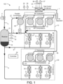
- CO 2 refrigeration system 100 may be a vapor compression refrigeration system which uses primarily carbon dioxide (CO 2 ) as a refrigerant.
- CO 2 refrigeration system 100 and is shown to include a system of pipes, conduits, or other fluid channels (e.g., fluid conduits 1, 3, 5, 7, 9, 13, 23, 25, 27, and 42) for transporting the CO 2 refrigerant between various components of CO 2 refrigeration system 100.
- CO 2 refrigeration system 100 The components of CO 2 refrigeration system 100 are shown to include a gas cooler/condenser 2, a high pressure valve 4, a receiver 6, a gas bypass valve 8, a medium-temperature (“MT”) subsystem 10, and a low-temperature (“LT”) subsystem 20.
- a gas cooler/condenser 2 The components of CO 2 refrigeration system 100 are shown to include a gas cooler/condenser 2, a high pressure valve 4, a receiver 6, a gas bypass valve 8, a medium-temperature (“MT”) subsystem 10, and a low-temperature (“LT”) subsystem 20.
- MT medium-temperature
- LT low-temperature
- Gas cooler/condenser 2 is a heat exchanger or other similar device for removing heat from the CO 2 refrigerant. Gas cooler/condenser 2 is shown receiving CO 2 gas from fluid conduit 1.
- the CO 2 gas in fluid conduit 1 may have a pressure within a range from approximately 45 bar to approximately 100 bar (i.e., about 650 psig to about 1450 psig), depending on ambient temperature and other operating conditions.
- gas cooler/condenser 2 may partially or fully condense CO 2 gas into liquid CO 2 (e.g., if system operation is in a subcritical region).
- the condensation process may result in fully saturated CO 2 liquid or a two-phase liquid-vapor mixture (e.g., having a thermodynamic vapor quality between 0 and 1).
- gas cooler/condenser 2 may cool the CO 2 gas (e.g., by removing superheat) without condensing the CO 2 gas into CO 2 liquid (e.g., if system operation is in a supercritical region).
- the cooling/condensation process is an isobaric process. Gas cooler/condenser 2 is shown outputting the cooled and/or condensed CO 2 refrigerant into fluid conduit 3.
- CO 2 refrigeration system 100 includes a temperature sensor 33 and a pressure sensor 34 configured to measure the temperature and pressure of the CO 2 refrigerant exiting gas cooler/condenser 2. Sensors 33 and 34 can be installed along fluid conduit 3 (as shown in FIG. 1 ), within gas cooler/condenser 2, or otherwise positioned to measure the temperature and pressure of the CO 2 refrigerant exiting gas cooler/condenser 2.
- the CO 2 refrigeration system 100 includes a condenser fan 35 configured to provide airflow across gas cooler/condenser 2. The speed of condenser fan 35 can be controlled to increase or decrease the airflow across gas cooler/condenser 2 to modulate the amount of cooling applied to the CO 2 refrigerant within gas cooler/condenser 2.
- CO 2 refrigeration system 100 also includes a temperature sensor 37 and a pressure sensor 38 configured to measure the temperature and pressure of the ambient air that flows across gas cooler/condenser 2 to provide cooling for the CO 2 refrigerant contained therein.
- High pressure valve 4 receives the cooled and/or condensed CO 2 refrigerant from fluid conduit 3 and outputs the CO 2 refrigerant to fluid conduit 5.
- High pressure valve 4 may control the pressure of the CO 2 refrigerant in gas cooler/condenser 2 by controlling an amount of CO 2 refrigerant permitted to pass through high pressure valve 4.
- high pressure valve 4 is a high pressure thermal expansion valve (e.g., if the pressure in fluid conduit 3 is greater than the pressure in fluid conduit 5). In such embodiments, high pressure valve 4 may allow the CO 2 refrigerant to expand to a lower pressure state.
- the expansion process may be an isenthalpic and/or adiabatic expansion process, resulting in a two-phase flash of the high pressure CO 2 refrigerant to a lower pressure, lower temperature state.
- the expansion process may produce a liquid/vapor mixture (e.g., having a thermodynamic vapor quality between 0 and 1).
- the CO 2 refrigerant expands to a pressure of approximately 38 bar (e.g., about 550 psig), which corresponds to a temperature of approximately 40° F (4,44°C).
- the CO 2 refrigerant then flows from fluid conduit 5 into receiver 6.
- Receiver 6 collects the CO 2 refrigerant from fluid conduit 5.
- receiver 6 may be a flash tank or other fluid reservoir.
- Receiver 6 includes a CO 2 liquid portion 16 and a CO 2 vapor portion 15 and may contain a partially saturated mixture of CO 2 liquid and CO 2 vapor.
- receiver 6 separates the CO 2 liquid from the CO 2 vapor.
- the CO 2 liquid may exit receiver 6 through fluid conduits 9.
- Fluid conduits 9 may be liquid headers leading to MT subsystem 10 and/or LT subsystem 20.
- the CO 2 vapor may exit receiver 6 through fluid conduit 7 (i.e., a refrigerant supply line). Fluid conduit 7 is shown leading the CO 2 vapor to a gas bypass valve 8 and a parallel compressor 26 (described in greater detail below).
- CO 2 refrigeration system 100 includes a temperature sensor 31 and a pressure sensor 32 configured to measure the temperature and pressure within receiver 6. Sensors 31 and 32 can be installed in or on receiver 6 (as shown in FIG. 1 ) or along any of the fluid conduits that contain CO 2 refrigerant at the same temperature and/or pressure as receiver 6 (i.e., fluid conduits 5, 7, 9, or 27).
- MT subsystem 10 is shown to include one or more expansion valves 11, one or more MT evaporators 12, and one or more MT compressors 14. In various embodiments, any number of expansion valves 11, MT evaporators 12, and MT compressors 14 may be present.
- Expansion valves 11 may be electronic expansion valves or other similar expansion valves. Expansion valves 11 are shown receiving liquid CO 2 refrigerant from fluid conduit 9 and outputting the CO 2 refrigerant to MT evaporators 12. Expansion valves 11 may cause the CO 2 refrigerant to undergo a rapid drop in pressure, thereby expanding the CO 2 refrigerant to a lower pressure, lower temperature two-phase state. In some embodiments, expansion valves 11 may expand the CO 2 refrigerant to a pressure of approximately 20 bar to 25 bar. The expansion process may be an isenthalpic and/or adiabatic expansion process.
- MT evaporators 12 are shown receiving the cooled and expanded CO 2 refrigerant from expansion valves 11.
- MT evaporators may be associated with display cases/devices (e.g., if CO 2 refrigeration system 100 is implemented in a supermarket setting).
- MT evaporators 12 may be configured to facilitate the transfer of heat from the display cases/devices into the CO 2 refrigerant. The added heat may cause the CO 2 refrigerant to evaporate partially or completely.
- the CO 2 refrigerant is fully evaporated in MT evaporators 12.
- the evaporation process may be an isobaric process.
- MT evaporators 12 are shown outputting the CO 2 refrigerant via suction line 13, leading to MT compressors 14.
- MT compressors 14 compress the CO 2 refrigerant into a superheated gas having a pressure within a range of approximately 45 bar to approximately 100 bar.
- the output pressure from MT compressors 14 may vary depending on ambient temperature and other operating conditions.
- MT compressors 14 operate in a transcritical mode. In operation, the CO 2 discharge gas exits MT compressors 14 and flows through fluid conduit 1 into gas cooler/condenser 2.
- LT subsystem 20 is shown to include one or more expansion valves 21, one or more LT evaporators 22, and one or more LT compressors 24. In various embodiments, any number of expansion valves 21, LT evaporators 22, and LT compressors 24 may be present. In some embodiments, LT subsystem 20 may be omitted and the CO 2 refrigeration system 100 may operate with an AC module or parallel compressor 26 interfacing with only MT subsystem 10.
- Expansion valves 21 may be electronic expansion valves or other similar expansion valves. Expansion valves 21 are shown receiving liquid CO 2 refrigerant from fluid conduit 9 and outputting the CO 2 refrigerant to LT evaporators 22. Expansion valves 21 may cause the CO 2 refrigerant to undergo a rapid drop in pressure, thereby expanding the CO 2 refrigerant to a lower pressure, lower temperature two-phase state.
- the expansion process may be an isenthalpic and/or adiabatic expansion process.
- expansion valves 21 may expand the CO 2 refrigerant to a lower pressure than expansion valves 11, thereby resulting in a lower temperature CO 2 refrigerant.
- LT subsystem 20 may be used in conjunction with a freezer system or other lower temperature display cases.
- LT evaporators 22 are shown receiving the cooled and expanded CO 2 refrigerant from expansion valves 21.
- LT evaporators may be associated with display cases/devices (e.g., if CO 2 refrigeration system 100 is implemented in a supermarket setting).
- LT evaporators 22 may be configured to facilitate the transfer of heat from the display cases/devices into the CO 2 refrigerant. The added heat may cause the CO 2 refrigerant to evaporate partially or completely.
- the evaporation process may be an isobaric process.
- LT evaporators 22 are shown outputting the CO 2 refrigerant via suction line 23, leading to LT compressors 24.
- LT compressors 24 compress the CO 2 refrigerant.
- LT compressors 24 may compress the CO 2 refrigerant to a pressure of approximately 30 bar (e.g., about 450 psig) having a saturation temperature of approximately 23°F.
- LT compressors 24 operate in a subcritical mode.
- LT compressors 24 are shown outputting the CO 2 refrigerant through discharge line 25.
- Discharge line 25 may be fluidly connected with the suction (e.g., upstream) side of MT compressors 14.
- CO 2 refrigeration system 100 is shown to include a gas bypass valve 8.
- Gas bypass valve 8 may receive the CO 2 vapor from fluid conduit 7 and output the CO 2 refrigerant to MT subsystem 10.
- gas bypass valve 8 is arranged in series with MT compressors 14.
- CO 2 vapor from receiver 6 may pass through both gas bypass valve 8 and MT compressors 14.
- MT compressors 14 may compress the CO 2 vapor passing through gas bypass valve 8 from a low pressure state (e.g., approximately 30 bar or lower) to a high pressure state (e.g., 45-100 bar).
- Gas bypass valve 8 may be positioned along fluid conduit 7 (i.e., a refrigerant supply line) or fluidly coupled to fluid conduit 7 such that gas bypass valve 8 is arranged in series with MT compressors 14 (upstream of MT compressors 14). Gas bypass valve 8 can be operated to control a flow of gas refrigerant from fluid conduit 7 into suction line 13. Gas bypass valve 8 may be operated to regulate or control the pressure within receiver 6 (e.g., by adjusting an amount of CO 2 refrigerant permitted to pass through gas bypass valve 8). For example, gas bypass valve 8 may be adjusted (e.g., variably opened or closed) to adjust the mass flow rate, volume flow rate, or other flow rates of the CO 2 refrigerant through gas bypass valve 8. Gas bypass valve 8 may be opened and closed (e.g., manually, automatically, by a controller, etc.) as needed to regulate the pressure within receiver 6.
- gas bypass valve 8 includes a sensor for measuring a flow rate (e.g., mass flow, volume flow, etc.) of the CO 2 refrigerant through gas bypass valve 8.
- gas bypass valve 8 includes an indicator (e.g., a gauge, a dial, etc.) from which the position of gas bypass valve 8 may be determined. This position may be used to determine the flow rate of CO 2 refrigerant through gas bypass valve 8, as such quantities may be proportional or otherwise related.
- gas bypass valve 8 may be a thermal expansion valve (e.g., if the pressure on the downstream side of gas bypass valve 8 is lower than the pressure in fluid conduit 7).
- the pressure within receiver 6 is regulated by gas bypass valve 8 to a pressure of approximately 38 bar, which corresponds to about 37°F.
- this pressure/temperature state may facilitate the use of copper tubing/piping for the downstream CO 2 lines of the system. Additionally, this pressure/temperature state may allow such copper tubing to operate in a substantially frost-free manner.
- the CO 2 vapor that is bypassed through gas bypass valve 8 is mixed with the CO 2 refrigerant gas exiting MT evaporators 12 (e.g., via suction line 13).
- the bypassed CO 2 vapor may also mix with the discharge CO 2 refrigerant gas exiting LT compressors 24 (e.g., via discharge line 25).
- the combined CO2 refrigerant gas may be provided to the suction side of MT compressors 14.
- the pressure immediately downstream of gas bypass valve 8 (i.e., in suction line 13) is lower than the pressure immediately upstream of gas bypass valve 8 (i.e., in fluid conduit 7). Therefore, the CO 2 vapor passing through gas bypass valve 8 and MT compressors 14 may be expanded (e.g., when passing through gas bypass valve 8) and subsequently recompressed (e.g., by MT compressors 14). This expansion and recompression may occur without any intermediate transfers of heat to or from the CO 2 refrigerant, which can be characterized as an inefficient energy usage.
- CO 2 refrigeration system 100 is shown to include a parallel compressor 26.
- Parallel compressor 26 may be arranged in parallel with MT compressors 14 and arranged in series with LT compressors 24. Although only one parallel compressor 26 is shown, any number of parallel compressors may be present.
- Parallel compressor 26 may be fluidly connected with receiver 6 and/or fluid conduit 7 via a connecting line 27.
- Parallel compressor 26 may be used to draw non-condensed CO 2 vapor from receiver 6 as a means for pressure control and regulation.
- using parallel compressor 26 to effectuate pressure control and regulation may provide a more efficient alternative to traditional pressure regulation techniques such as bypassing CO 2 vapor through bypass valve 8 to the lower pressure suction side of MT compressors 14.
- parallel compressor 26 may be operated (e.g., by a controller 50) to achieve a desired pressure within receiver 6.
- controller 50 may receive pressure measurements from a pressure sensor 32 monitoring the pressure within receiver 6 and may activate or deactivate parallel compressor 26 based on the pressure measurements.
- parallel compressor 26 compresses the CO 2 vapor received via connecting line 27 and discharges the compressed gas into discharge line 42.
- Discharge line 42 may be fluidly connected with fluid conduit 1.
- parallel compressor 26 may operate in parallel with MT compressors 14 by discharging the compressed CO 2 gas into a shared fluid conduit (e.g., fluid conduit 1).
- Parallel compressor 26 may be arranged in parallel with both gas bypass valve 8 and with MT compressors 14. CO 2 vapor exiting receiver 6 may pass through either parallel compressor 26 or the series combination of gas bypass valve 8 and MT compressors 14. Parallel compressor 26 may receive the CO 2 vapor at a relatively higher pressure (e.g., from fluid conduit 7) than the CO 2 vapor received by MT compressors 14 (e.g., from suction line 13). This differential in pressure may correspond to the pressure differential across gas bypass valve 8. In some embodiments, parallel compressor 26 may require less energy to compress an equivalent amount of CO 2 vapor to the high pressure state (e.g., in fluid conduit 1) as a result of the higher pressure of CO 2 vapor entering parallel compressor 26. Therefore, the parallel route including parallel compressor 26 may be a more efficient alternative to the route including gas bypass valve 8 and MT compressors 14.
- gas bypass valve 8 is omitted and the pressure within receiver 6 is regulated using parallel compressor 26.
- parallel compressor 26 is omitted and the pressure within receiver 6 is regulated using gas bypass valve 8.
- both gas bypass valve 8 and parallel compressor 26 are used to regulate the pressure within receiver 6. All such variations are within the scope of the present invention.
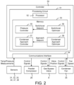
- Controller 50 receives signals from one or more measurement devices (e.g., pressure sensors, temperature sensors, flow sensors, etc.) located within CO 2 refrigeration system 100.
- controller 50 is shown receiving temperature and pressure measurements from sensors 31-34 and 37-38, a valve position signal from gas bypass valve 8, and a fan speed signal from condenser fan 35.
- Controller 50 may use the input signals to determine appropriate control actions for controllable devices of CO 2 refrigeration system 100 (e.g., compressors 14 and 24, parallel compressor 26, condenser fan 35, valves 4, 8, 11, and 21, flow diverters, power supplies, etc.).
- controller 50 is shown providing control signals to parallel compressor 26, gas bypass valve 8, and condenser fan 35.
- controller 50 is configured to operate gas bypass valve 8 and/or parallel compressor 26 to maintain the CO 2 pressure within receiving tank 6 at a desired setpoint or within a desired range. In some embodiments, controller 50 operates gas bypass valve 8 and parallel compressor 26 based on the temperature of the CO 2 refrigerant at the outlet of gas cooler/condenser 2. In other embodiments, controller 50 operates gas bypass valve 8 and parallel compressor 26 based a flow rate (e.g., mass flow, volume flow, etc.) of CO 2 refrigerant through gas bypass valve 8. Controller 50 may use a valve position of gas bypass valve 8 as a proxy for CO 2 refrigerant flow rate. In some embodiments, controller 50 operates high pressure valve 4 and expansion valves 11 and 21 to regulate the flow of refrigerant in system 100.
- controller 50 operates high pressure valve 4 and expansion valves 11 and 21 to regulate the flow of refrigerant in system 100.
- Controller 50 may include feedback control functionality for adaptively operating the various components of CO 2 refrigeration system 100.
- controller 50 may receive a setpoint (e.g., a temperature setpoint, a pressure setpoint, a flow rate setpoint, a power usage setpoint, etc.) and operate one or more components of system 100 to achieve the setpoint.
- the setpoint may be specified by a user (e.g., via a user input device, a graphical user interface, a local interface, a remote interface, etc.) or automatically determined by controller 50 based on a history of data measurements.
- controller 50 includes some or all of the features of the controller described in PCT Patent Application No. PCT/US2016/044164 filed July 27, 2016 , published as WO2017/023632A .
- Controller 50 may be a proportional-integral (PI) controller, a proportional-integral-derivative (PID) controller, a pattern recognition adaptive controller (PRAC), a model recognition adaptive controller (MRAC), a model predictive controller (MPC), or any other type of controller employing any type of control functionality.
- controller 50 is a local controller for CO 2 refrigeration system 100.
- controller 50 is a supervisory controller for a plurality of controlled subsystems (e.g., a refrigeration system, an AC system, a lighting system, a security system, etc.).
- controller 50 may be a controller for a comprehensive building management system incorporating CO 2 refrigeration system 100. Controller 50 may be implemented locally, remotely, or as part of a cloud-hosted suite of building management applications.
- controller 50 is shown to include a communications interface 54 and a processing circuit 51.
- Communications interface 54 can be or include wired or wireless interfaces (e.g., jacks, antennas, transmitters, receivers, transceivers, wire terminals, etc.) for conducting electronic data communications.
- communications interface 54 may be used to conduct communications with gas bypass valve 8, parallel compressor 26, compressors 14 and 24, high pressure valve 4, various data acquisition devices within CO 2 refrigeration system 100 (e.g., temperature sensors, pressure sensors, flow sensors, etc.) and/or other external devices or data sources.
- Data communications may be conducted via a direct connection (e.g., a wired connection, an ad-hoc wireless connection, etc.) or a network connection (e.g., an Internet connection, a LAN, WAN, or WLAN connection, etc.).
- communications interface 54 can include an Ethernet card and port for sending and receiving data via an Ethernet-based communications link or network.
- communications interface 54 can include a Wi-Fi transceiver or a cellular or mobile phone transceiver for communicating via a wireless communications network.
- Processing circuit 51 is shown to include a processor 52 and memory 53.
- Processor 52 can be implemented as a general purpose processor, an application specific integrated circuit (ASIC), one or more field programmable gate arrays (FPGAs), a group of processing components, a microcontroller, or other suitable electronic processing components.
- Memory 53 e.g., memory device, memory unit, storage device, etc.
- Memory 53 may be one or more devices (e.g., RAM, ROM, solid state memory, hard disk storage, etc.) for storing data and/or computer code for completing or facilitating the various processes, layers and modules described in the present application.
- Memory 53 may be or include volatile memory or non-volatile memory.
- Memory 53 may include database components, object code components, script components, or any other type of information structure for supporting the various activities and information structures described in the present application. According to an exemplary embodiment, memory 53 is communicably connected to processor 52 via processing circuit 51 and includes computer code for executing (e.g., by processing circuit 51 and/or processor 52) one or more processes or control features described herein.
- controller 50 is shown to include a pressure controller 55.
- Pressure controller 55 can be configured to control the pressure within receiver 6 by operating gas bypass valve 8 and/or parallel compressor 26.
- Pressure controller 55 may use parallel compressor 26 to control the pressure within receiver 6 when the amount of CO 2 refrigerant gas being produced by CO 2 refrigeration system 100 is sufficient to sustain the operation of parallel compressor 26.
- pressure controller 55 may regulate the pressure within receiver 6 by directing the CO 2 refrigerant gas through gas bypass valve 8 to be compressed by MT compressors 14. If CO 2 refrigeration system 100 begins producing enough CO 2 refrigerant gas to sustain the operation of parallel compressor 26, pressure controller 55 may close gas bypass valve 8 and activate parallel compressor 26.
- Pressure controller 55 may determine whether CO 2 refrigeration system 100 produces enough CO 2 refrigerant gas to sustain the operation of parallel compressor 26 by comparing a process variable to a switchover setpoint.
- the process variable may be any variable received as a feedback from CO 2 refrigeration system 100 including, for example, the pressure of the CO 2 refrigerant within receiver 6, the flow rate of the CO 2 refrigerant through gas bypass valve 8, or the position of gas bypass valve 8.
- pressure controller 55 may close gas bypass valve 8 and activate parallel compressor 26.
- the switchover setpoint may be determined automatically by switchover optimizer 56 (described in greater detail with reference to FIG. 3 ).
- pressure controller 55 may compare the pressure within receiver 6 to a pressure setpoint.
- the pressure setpoint may be the same as the switchover setpoint or may be different from the switchover setpoint. Once the pressure of the CO 2 refrigerant gas within receiver 6 drops below the pressure setpoint, pressure controller 55 may deactivate parallel compressor 26 and operate gas bypass valve 8 to control the pressure within receiver 6.
- controller 50 is shown to include a condenser approach controller 57.
- Condenser approach controller 57 is configured to operate condenser fan 35 to maintain the condenser approach temperature at or below an approach setpoint.
- the condenser approach temperature is defined as the difference between the temperature of the CO 2 refrigerant exiting gas cooler/condenser 2 (i.e., the temperature measured by temperature sensor 33) and the temperature of the ambient air used to provide cooling for the CO 2 refrigerant in gas cooler/condenser 2 (i.e., the airflow controlled by operating condenser fan 35).
- the temperature of the ambient air may be measured by temperature sensor 37.
- condenser approach controller 57 increases the speed of condenser fan 35 to provide more cooling for the CO 2 refrigerant in gas cooler/condenser 2. However, if the approach temperature is less than or equal to the approach setpoint, condenser approach controller 57 may maintain condenser fan 35 at its current speed.
- the approach setpoint is determined automatically by condenser approach optimizer 58 (described in greater detail with reference to FIG. 4 ).
- controller 50 is shown to include a switchover optimizer 56.
- Switchover optimizer 56 can be configured to determine an optimal value for the switchover setpoint provided to pressure controller 55.
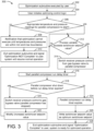
- switchover optimizer 56 performs process 300 (shown in FIG. 3 ) to determine the optimal value for the switchover setpoint.
- Process 300 begins when the optimization subroutine is executed by a user (step 302) and the user initiates the optimizing control logic (step 304).
- Switchover optimizer 56 may determine whether appropriate temperature and pressure readings (measured by sensors 31-34 and 37-38) are present for parallel compression to start (step 306). Appropriate temperature and pressure readings should fall within min and max operating values in order for parallel compressor 26 to successfully start.
- switchover optimizer 56 may generate a notification that the optimization cannot execute until temperatures and pressures are within min and max boundaries (step 308). Switchover optimizer 56 may then exit the optimization subroutine and signal "Optimization NOT Complete" to the user (step 310). CO 2 refrigeration system 100 may then resume normal operation. If at any point during process 300, the temperature and pressure readings in the system fall out of the min and max operating values, the optimization subroutine may stop and exit, notifying the user that the system has not completed the optimization routine but the system will operate as normal.
- switchover optimizer 56 may determine whether the process variable (e.g., pressure within receiver 6, position of gas bypass valve 8, refrigerant flow rate through gas bypass valve 8, etc.) exceeds a switchover setpoint value (step 312). Initially, the switchover setpoint value may be set to a default or initial value, which can be optimized by performing the subsequent steps of process 300. If the process variable does not exceed the switchover setpoint value (i.e., the result of step 312 is "no"), switchover optimizer 56 may wait until the criterion in step 312 is satisfied.
- the process variable e.g., pressure within receiver 6, position of gas bypass valve 8, refrigerant flow rate through gas bypass valve 8, etc.
- switchover optimizer 56 may switch the receiver pressure control from gas bypass valve 8 to parallel compressor 26 (step 314).
- Step 314 may include closing gas bypass valve 8 and activating parallel compressor 26.
- switchover optimizer 56 may start a parallel compressor run delay timer (step 316) and determine whether a shutdown of parallel compressor 26 occurs before the run delay timer expires (step 318).
- a shutdown of parallel compressor 26 may occur when the amount of CO 2 refrigerant gas being produced by CO 2 refrigeration system 100 is insufficient to sustain the operation of parallel compressor 26.
- pressure controller 55 may shutdown parallel compressor 26 when the pressure within receiver 6 drops below a pressure setpoint.
- switchover optimizer 56 may switch the receiver pressure control from parallel compressor 26 to gas bypass valve 8 (step 320). Switchover optimizer 56 may then modify (increase) the switchover setpoint value (step 322) and process 300 may return to step 312. Increasing the switchover setpoint value in step 322 will require a greater value of the process variable to trigger a switchover to parallel compressor 26 in step 312. Accordingly, it will be less likely that the amount of CO 2 refrigerant gas being produced by CO 2 refrigeration system 100 is insufficient to sustain the operation of parallel compressor 26 for at least the duration of the compressor run delay timer next time steps 312-318 are performed. Steps 312-322 can be repeated as many times as necessary to cause parallel compressor 26 to remain active for at least the duration of the run delay timer in step 318.
- switchover optimizer 56 may wait until the run delay timer expires (step 324) and write the switchover setpoint value as the optimum switchover setpoint (step 326). Switchover optimizer 56 may then exit the optimization subroutine and signal "Optimization Complete" to the user (step 328). CO 2 refrigeration system 100 may then be ready for optimized operation.
- controller 50 is shown to include a condenser approach optimizer 58.
- Condenser approach optimizer 58 is configured to determine an optimal value for the approach setpoint provided to condenser approach controller 57.
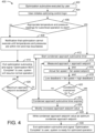
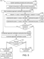
- condenser approach optimizer 57 performs process 400 (shown in FIG. 4 ) to determine the optimal value for the condenser approach setpoint.
- Process 400 begins when the optimization subroutine is executed by a user (step 402) and the user initiates the optimizing control logic (step 404).
- Condenser approach optimizer 58 may determine whether appropriate temperature and pressure readings (measured by sensors 31-34 and 37-38) are present for subcritical operation to start (step 406). Appropriate temperature and pressure readings should fall within min and max operating values in order for gas cooler/condenser 2 to operate in a subcritical mode.
- condenser approach optimizer 58 may generate a notification that the optimization cannot execute until temperatures and pressures are within min and max boundaries (step 408). Condenser approach optimizer 58 may then exit the optimization subroutine and signal "Optimization NOT Complete" to the user (step 410). CO 2 refrigeration system 100 may then resume normal operation. If at any point during process 400, the temperature and pressure readings in the system fall out of the min and max operating values, the optimization subroutine may stop and exit, notifying the user that the system has not completed the optimization routine but the system will operate as normal.
- condenser approach optimizer 58 starts a condenser approach subroutine timer (step 412). Condenser approach optimizer 58 then checks whether several conditions 414-418 are maintained continuously for at least a minimum amount of time Tmin (step 420). In various embodiments, the minimum amount of time Tmin may be shorter than the duration of the condenser approach subroutine timer or equal to the duration of the condenser approach subroutine timer.
- Condition 414 is satisfied if the measured approach (i.e., the measured difference between the temperature of the CO 2 refrigerant exiting gas cooler/condenser 2 and the ambient air temperature) is less than an approach setpoint.
- the temperature of the CO 2 refrigerant exiting gas cooler/condenser 2 may be measured by temperature sensor 33, whereas the ambient air temperature may be measured by temperature sensor 37.
- the approach setpoint has a default or initial value, which can be optimized by performing the subsequent steps of process 400.
- Condition 416 is satisfied if the actual speed of condenser fan 35 is less than a fan speed setpoint.
- the fan speed setpoint may be defined by a user or otherwise provided as an input to process 400.
- Condition 418 is satisfied if the actual speed of condenser fan 35 is between a low deadband fan speed value and a high deadband fan speed value.
- condenser approach optimizer 58 may wait until all of conditions 414-418 are satisfied and repeat step 420. Step 420 may be repeated as many times as necessary until either all of conditions 414-418 are maintained for at least the minimum amount of time Tmin or the condenser approach subroutine timer has expired.
- condenser approach optimizer 58 increases the approach setpoint value (step 424) and check whether the approach setpoint value exceeds a maximum approach setpoint (step 426). If the maximum approach setpoint is exceeded (i.e., the result of step 426 is "yes"), condenser approach optimizer 58 exits the optimization subroutine and signals "Optimization NOT Complete" to the user (step 410). CO 2 refrigeration system 100 may then resume normal operation.
- step 426 condenser approach optimizer 58 returns to step 412. Steps 412-426 may be repeated as many times as necessary until either all of conditions 414-418 are maintained for at least the minimum amount of time Tmin in step 420 or the maximum approach setpoint is exceeded in step 426.
- condenser approach optimizer 58 may write the condenser approach setpoint value as the optimum condenser approach setpoint (step 428). Condenser approach optimizer 58 may then exit the optimization subroutine and signal "Optimization Complete" to the user (step 430). CO 2 refrigeration system 100 may then be ready for optimized operation.
- Process 500 may be performed by controller 50 after condenser approach optimization process 400 is performed to ensure that CO 2 refrigeration system 100 continues to operate as expected.
- controller 50 may record the optimized approach setpoint and the corresponding values for the fan speed (i.e., the optimized fan speed) and the fan power (i.e., the optimized fan power).
- Such variables can be stored in memory and used during process 500.
- Process 500 may be performed when CO 2 refrigeration system 100 is operating normally and continuously (condition 502) and when the ambient temperature matches the ambient temperature recorded when performing condenser approach optimization process 400 (condition 504).
- controller 50 may start a condenser approach verification subroutine timer (step 506). Controller 50 may then check whether several conditions 508-512 are maintained continuously for at least a minimum amount of time Tmin (step 514). The temperature of the CO 2 refrigerant exiting gas cooler/condenser 2 may be measured by temperature sensor 33 and the ambient air temperature may be measured by temperature sensor 37.
- Condition 508 is satisfied if the measured approach (i.e., the measured difference between the temperature of the CO 2 refrigerant exiting gas cooler/condenser 2 and the ambient air temperature) is maintained at the optimal condenser approach setpoint plus or minus a predetermined percentage of the approach setpoint (i.e., (Setpoint - % value) ⁇ measured approach ⁇ (setpoint + % value)).
- Condition 510 is satisfied if the measured fan speed is maintained at the optimal fan speed plus or minus a predetermined percentage of the optimal fan speed (i.e., (optimized fan speed - % value) ⁇ fan speed ⁇ (optimized fan speed + % value)).
- Condition 512 is satisfied if the measured fan speed is maintained at the optimal fan power plus or minus a predetermined percentage of the optimal fan power (i.e., (optimized fan power - % value) ⁇ fan power ⁇ (optimized fan power + % value)).
- controller 50 may wait until all of conditions 508-512 are satisfied and repeat step 514. Step 514 may be repeated as many times as necessary until either all of conditions 508-512 are maintained for at least the minimum amount of time Tmin or the condenser approach verification subroutine timer has expired.
- controller 50 may exit the verification subroutine (step 522).
- controller 50 may increment an approach verification counter (step 518) and check whether the approach verification counter is less than a threshold (step 520). If the approach verification counter is less than the threshold (i.e., the result of step 520 is "yes"), controller 50 may exit the verification subroutine (step 522). However, if the approach verification counter is not less than the threshold (i.e., the result of step 520 is "no"), controller 50 may exit the verification subroutine (step 524) and perform the condenser approach optimization subroutine (i.e., process 400) to update the optimized values used in conditions 508-512.
- the condenser approach optimization subroutine i.e., process 400
- Coupled means the joining of two members directly or indirectly to one another. Such joining may be stationary (e.g., permanent) or moveable (e.g., removable or releasable). Such joining may be achieved with the two members or the two members and any additional intermediate members being integrally formed as a single unitary body with one another or with the two members or the two members and any additional intermediate members being attached to one another.
Landscapes
- Engineering & Computer Science (AREA)
- Physics & Mathematics (AREA)
- Mechanical Engineering (AREA)
- Thermal Sciences (AREA)
- General Engineering & Computer Science (AREA)
- Chemical & Material Sciences (AREA)
- Chemical Kinetics & Catalysis (AREA)
- Devices That Are Associated With Refrigeration Equipment (AREA)
- Control Of Positive-Displacement Pumps (AREA)
Claims (8)
- Système de réfrigération (100) comprenant :un refroidisseur/condenseur de gaz (2) configuré pour éliminer la chaleur d'un fluide frigorigène circulant à travers le refroidisseur/condenseur de gaz (2) et comprenant une sortie par laquelle le fluide frigorigène sort du refroidisseur/condenseur de gaz (2) ;un ventilateur (35) pouvant fonctionner pour provoquer un flux d'air à travers le refroidisseur/condenseur de gaz (2) et configuré pour fonctionner à plusieurs vitesses de ventilateur différentes pour moduler une quantité de chaleur éliminée du fluide frigorigène circulant à travers le refroidisseur/condenseur de gaz (2) ;caractérisé par un contrôleur (50) configuré pour :calculer une température d'approche du condenseur en soustrayant une température du flux d'air provoqué par le ventilateur (35) d'une température du fluide frigorigène sortant du refroidisseur/condenseur de gaz (2) ;faire fonctionner le ventilateur (35) pour moduler la quantité de chaleur retirée du fluide frigorigène circulant dans le refroidisseur de gaz/condenseur (2) pour maintenir la température d'approche du condenseur à ou en dessous d'un point de consigne d'approche du condenseur ; etajuster automatiquement le point de consigne d'approche du condenseur en réponse à la quantité de chaleur retirée du fluide frigorigène qui est insuffisante pour maintenir la température d'approche du condenseur à ou en dessous du point de consigne d'approche du condenseur ;dans lequel l'ajustement automatique du point de consigne d'approche du condenseur comprend l'exécution d'un processus d'ajustement du point de consigne d'approche comprenant :le démarrage d'un minuteur de sous-programme d'approche du condenseur ;la surveillance de la température d'approche du condenseur et d'une vitesse de ventilateur du ventilateur (35) après le démarrage du minuteur de sous-programme d'approche du condenseur ;l'augmentation automatique du point de consigne d'approche du condenseur à un point de consigne d'approche du condenseur ajusté en réponse à la température d'approche du condenseur et à la vitesse du ventilateur qui ne parviennent pas à maintenir des conditions prédéterminées pendant au moins une durée minimale avant l'expiration du minuteur de sous-programme d'approche du condenseur ; etla répétition des étapes de démarrage, de surveillance et d'augmentation automatique jusqu'à ce que la température d'approche du condenseur et la vitesse du ventilateur maintiennent les conditions prédéterminées pendant au moins la durée minimale avant l'expiration du minuteur de sous-programme d'approche du condenseur.
- Système de réfrigération (100) selon la revendication 1, dans lequel les conditions prédéterminées comprennent au moins l'une des conditions suivantes :la température d'approche du condenseur étant inférieure au point de consigne d'approche du condenseur ;la vitesse du ventilateur étant inférieure à un point de consigne de vitesse du ventilateur ; etla vitesse du ventilateur étant comprise entre une valeur de zone morte basse et une valeur de zone morte haute.
- Système de réfrigération (100) selon la revendication 1 ou la revendication 2, dans lequel le processus d'ajustement du point de consigne d'approche comprend l'écriture du point de consigne d'approche du condenseur ajusté comme point de consigne d'approche du condenseur optimal en réponse à la température d'approche du condenseur et à la vitesse du ventilateur maintenant les conditions prédéterminées pendant au moins la durée minimale.
- Système de réfrigération (100) selon l'une quelconque des revendications 1 à 3, dans lequel le processus de réglage du point de consigne d'approche comprend en outre :la détermination que le point de consigne d'approche du condenseur ajusté dépasse un point de consigne d'approche maximal après avoir augmenté automatiquement le point de consigne d'approche du condenseur jusqu'au point de consigne d'approche du condenseur ajusté ; etle redémarrage du minuteur de sous-programme d'approche du condenseur en réponse au fait que le point de consigne d'approche du condenseur ajusté ne dépasse pas le point de consigne d'approche maximal.
- Système de réfrigération (100) selon la revendication 4, dans lequel le processus de réglage du point de consigne d'approche comprend en outre la fin du processus de réglage du point de consigne d'approche en réponse au minuteur de sous-programme d'approche du condenseur en réponse au fait que le point de consigne d'approche du condenseur ajusté dépasse le point de consigne d'approche maximal.
- Système de réfrigération (100) selon l'une quelconque des revendications 1 à 5, dans lequel le contrôleur (50) est configuré pour :déterminer si le refroidisseur/condenseur de gaz (2) fonctionne dans un mode sous-critique ; etexécuter le processus d'ajustement du point de consigne d'approche en réponse à la détermination que le refroidisseur/condenseur de gaz (2) fonctionne en mode sous-critique.
- Système de réfrigération (100) selon l'une quelconque des revendications précédentes, dans lequel le contrôleur (50) est configuré pour :obtenir une mesure d'une température de l'air ambiant qui se produit tout en ajustant automatiquement le point de consigne d'approche du condenseur ; etstocker une association entre le point de consigne d'approche du condenseur qui résulte de l'ajustement automatique du point de consigne d'approche du condenseur et la température de l'air ambiant mesurée.
- Système de réfrigération (100) selon la revendication 7, dans lequel le contrôleur (50) est configuré pour, en réponse à une température de l'air ambiant actuelle correspondant à la température de l'air ambiant mesurée associée au point de consigne d'approche du condenseur :démarrer un minuteur de sous-programme de vérification d'approche du condenseur ;surveiller la température d'approche du condenseur et une vitesse de ventilateur du ventilateur (35) ; etvérifier que la température d'approche du condenseur et la vitesse du ventilateur maintiennent des conditions prédéterminées pendant au moins une durée minimale avant l'expiration du minuteur de sous-programme de vérification d'approche du condenseur.
Applications Claiming Priority (2)
| Application Number | Priority Date | Filing Date | Title |
|---|---|---|---|
| US201862683099P | 2018-06-11 | 2018-06-11 | |
| EP19178441.2A EP3581860B1 (fr) | 2018-06-11 | 2019-06-05 | Système de réfrigération de co2 avec optimisation de commande automatisée et une méthode pour operer un tel système de réfrigération |
Related Parent Applications (1)
| Application Number | Title | Priority Date | Filing Date |
|---|---|---|---|
| EP19178441.2A Division EP3581860B1 (fr) | 2018-06-11 | 2019-06-05 | Système de réfrigération de co2 avec optimisation de commande automatisée et une méthode pour operer un tel système de réfrigération |
Publications (2)
| Publication Number | Publication Date |
|---|---|
| EP3929502A1 EP3929502A1 (fr) | 2021-12-29 |
| EP3929502B1 true EP3929502B1 (fr) | 2024-12-04 |
Family
ID=66770355
Family Applications (2)
| Application Number | Title | Priority Date | Filing Date |
|---|---|---|---|
| EP19178441.2A Active EP3581860B1 (fr) | 2018-06-11 | 2019-06-05 | Système de réfrigération de co2 avec optimisation de commande automatisée et une méthode pour operer un tel système de réfrigération |
| EP21192656.3A Active EP3929502B1 (fr) | 2018-06-11 | 2019-06-05 | Système de réfrigération de co2 avec optimisation de commande automatisée |
Family Applications Before (1)
| Application Number | Title | Priority Date | Filing Date |
|---|---|---|---|
| EP19178441.2A Active EP3581860B1 (fr) | 2018-06-11 | 2019-06-05 | Système de réfrigération de co2 avec optimisation de commande automatisée et une méthode pour operer un tel système de réfrigération |
Country Status (6)
| Country | Link |
|---|---|
| US (2) | US11353246B2 (fr) |
| EP (2) | EP3581860B1 (fr) |
| BR (1) | BR102019011489A2 (fr) |
| CA (1) | CA3045188A1 (fr) |
| ES (2) | ES2895664T3 (fr) |
| MX (2) | MX2019006698A (fr) |
Families Citing this family (16)
| Publication number | Priority date | Publication date | Assignee | Title |
|---|---|---|---|---|
| EP3023712A1 (fr) * | 2014-11-19 | 2016-05-25 | Danfoss A/S | Procédé pour commander un système de compression de vapeur avec un récepteur |
| US11353246B2 (en) | 2018-06-11 | 2022-06-07 | Hill Phoenix, Inc. | CO2 refrigeration system with automated control optimization |
| EP3628942B1 (fr) | 2018-09-25 | 2021-01-27 | Danfoss A/S | Procédé permettant de commander un système de compression de vapeur à une pression d'aspiration réduite |
| EP3628940B1 (fr) | 2018-09-25 | 2022-04-20 | Danfoss A/S | Procédé pour commander un système de compression de vapeur sur la base de flux estimé |
| DE102019201291A1 (de) * | 2019-02-01 | 2020-08-06 | BSH Hausgeräte GmbH | Kältegerät mit parallelen Verdampfern und Betriebsverfahren dafür |
| US11287165B2 (en) * | 2020-05-20 | 2022-03-29 | Hill Phoenix, Inc. | Refrigeration system with adiabatic electrostatic cooling device |
| CA3183998A1 (fr) | 2020-06-23 | 2021-12-30 | Jeffrey E. Newel | Systeme de refroidissement comprenant un systeme de distribution et une unite de refroidissement |
| WO2022053503A1 (fr) * | 2020-09-10 | 2022-03-17 | Advansor A/S | Système de réfrigération à gaz carbonique et procédé de mise en opération d'un système de réfrigération |
| MX2023004430A (es) | 2020-10-16 | 2023-07-11 | Hill Phoenix Inc | Sistema de refrigeración de co2 con control de enfriador externo. |
| PL4016207T3 (pl) * | 2020-12-18 | 2023-05-08 | Danfoss A/S | Sposób konfiguracji nastaw dla układu sprężania par |
| EP4060255B1 (fr) * | 2021-03-18 | 2023-08-09 | Danfoss A/S | Procédé permettant de commander un système de compression de vapeur avec un compresseur récepteur |
| EP4060254A1 (fr) | 2021-03-18 | 2022-09-21 | Danfoss A/S | Procédé permettant de commander un système de compression de vapeur à l'aide d'une soupape de dérivation |
| CN114459133B (zh) * | 2022-01-10 | 2024-07-05 | 广东建设职业技术学院 | 一种中央空调系统节能控制方法及节能控制系统 |
| US20240295352A1 (en) * | 2023-03-02 | 2024-09-05 | Hill Phoenix, Inc. | Precise Adiabatic Water Control |
| US12498157B2 (en) * | 2023-05-16 | 2025-12-16 | Copeland Lp | Systems, controllers, and methods for controlling a CO2 refrigeration system |
| US20250362062A1 (en) * | 2024-05-21 | 2025-11-27 | Hill Phoenix, Inc. | Co2 refrigeration system with superheat control |
Citations (1)
| Publication number | Priority date | Publication date | Assignee | Title |
|---|---|---|---|---|
| EP2999932B1 (fr) * | 2013-05-03 | 2019-07-17 | Hill Phoenix Inc. | Systèmes et procédés de régulation de pression dans un système de réfrigération co2 |
Family Cites Families (12)
| Publication number | Priority date | Publication date | Assignee | Title |
|---|---|---|---|---|
| US5735134A (en) | 1996-05-30 | 1998-04-07 | Massachusetts Institute Of Technology | Set point optimization in vapor compression cycles |
| US6578373B1 (en) * | 2000-09-21 | 2003-06-17 | William J. Barbier | Rate of change detector for refrigerant floodback |
| KR101338012B1 (ko) | 2002-12-09 | 2013-12-09 | 허드슨 테크놀로지스, 인코포레이티드 | 냉각 시스템 최적화 방법 및 장치 |
| US7275377B2 (en) | 2004-08-11 | 2007-10-02 | Lawrence Kates | Method and apparatus for monitoring refrigerant-cycle systems |
| US7752854B2 (en) | 2005-10-21 | 2010-07-13 | Emerson Retail Services, Inc. | Monitoring a condenser in a refrigeration system |
| US20150059373A1 (en) | 2013-09-05 | 2015-03-05 | Beckett Performance Products, Llc | Superheat and sub-cooling control of refrigeration system |
| EP3023712A1 (fr) * | 2014-11-19 | 2016-05-25 | Danfoss A/S | Procédé pour commander un système de compression de vapeur avec un récepteur |
| EP3023713A1 (fr) * | 2014-11-19 | 2016-05-25 | Danfoss A/S | Procédé pour commander un système de compression de vapeur avec un éjecteur |
| WO2017023632A1 (fr) | 2015-08-03 | 2017-02-09 | Hill Phoenix, Inc. | Système de réfrigération au co2 à échange de chaleur direct de co2 |
| MX374485B (es) * | 2015-10-20 | 2025-03-06 | Danfoss As | Metodo para controlar un sistema de compresion de vapor en modo de eyector durante un tiempo prolongado. |
| US20180031292A1 (en) * | 2016-07-26 | 2018-02-01 | Mingsheng Liu | Condenser Pressure Control System and Method |
| US11353246B2 (en) | 2018-06-11 | 2022-06-07 | Hill Phoenix, Inc. | CO2 refrigeration system with automated control optimization |
-
2019
- 2019-06-03 US US16/429,478 patent/US11353246B2/en active Active
- 2019-06-04 BR BR102019011489A patent/BR102019011489A2/pt not_active Application Discontinuation
- 2019-06-04 CA CA3045188A patent/CA3045188A1/fr active Pending
- 2019-06-05 ES ES19178441T patent/ES2895664T3/es active Active
- 2019-06-05 ES ES21192656T patent/ES3004937T3/es active Active
- 2019-06-05 EP EP19178441.2A patent/EP3581860B1/fr active Active
- 2019-06-05 EP EP21192656.3A patent/EP3929502B1/fr active Active
- 2019-06-07 MX MX2019006698A patent/MX2019006698A/es unknown
- 2019-06-07 MX MX2023004752A patent/MX2023004752A/es unknown
-
2021
- 2021-09-01 US US17/464,321 patent/US11674719B2/en active Active
Patent Citations (1)
| Publication number | Priority date | Publication date | Assignee | Title |
|---|---|---|---|---|
| EP2999932B1 (fr) * | 2013-05-03 | 2019-07-17 | Hill Phoenix Inc. | Systèmes et procédés de régulation de pression dans un système de réfrigération co2 |
Also Published As
| Publication number | Publication date |
|---|---|
| US11353246B2 (en) | 2022-06-07 |
| US11674719B2 (en) | 2023-06-13 |
| MX2019006698A (es) | 2019-12-12 |
| EP3581860B1 (fr) | 2021-09-15 |
| US20210396433A1 (en) | 2021-12-23 |
| EP3581860A1 (fr) | 2019-12-18 |
| ES2895664T3 (es) | 2022-02-22 |
| MX2023004752A (es) | 2023-05-10 |
| EP3929502A1 (fr) | 2021-12-29 |
| BR102019011489A2 (pt) | 2019-12-24 |
| CA3045188A1 (fr) | 2019-12-11 |
| ES3004937T3 (en) | 2025-03-13 |
| US20190376728A1 (en) | 2019-12-12 |
Similar Documents
| Publication | Publication Date | Title |
|---|---|---|
| EP3929502B1 (fr) | Système de réfrigération de co2 avec optimisation de commande automatisée | |
| US11680738B2 (en) | CO2 refrigeration system with high pressure valve control based on coefficient of performance | |
| US10502461B2 (en) | CO2 refrigeration system with direct CO2 heat exchange for building temperature control | |
| US10663201B2 (en) | CO2 refrigeration system with supercritical subcooling control | |
| US20210364210A1 (en) | Systems and Methods for Pressure Control in a CO2 Refrigeration System | |
| EP3572741B1 (fr) | Système de réfrigération doté d'un système de contrôle d'huile | |
| US20190301773A1 (en) | A method for controlling a vapour compression system during gas bypass valve malfunction | |
| US12571565B2 (en) | CO2 refrigeration system with external coolant control | |
| US20240151437A1 (en) | Co2 refrigeration system with convertible compressors | |
| US20240110736A1 (en) | Co2 refrigeration system with multiple receivers | |
| US12487017B2 (en) | CO2 refrigeration system with supercritical subcooling control | |
| US20250362062A1 (en) | Co2 refrigeration system with superheat control |
Legal Events
| Date | Code | Title | Description |
|---|---|---|---|
| PUAI | Public reference made under article 153(3) epc to a published international application that has entered the european phase |
Free format text: ORIGINAL CODE: 0009012 |
|
| STAA | Information on the status of an ep patent application or granted ep patent |
Free format text: STATUS: THE APPLICATION HAS BEEN PUBLISHED |
|
| AC | Divisional application: reference to earlier application |
Ref document number: 3581860 Country of ref document: EP Kind code of ref document: P |
|
| AK | Designated contracting states |
Kind code of ref document: A1 Designated state(s): AL AT BE BG CH CY CZ DE DK EE ES FI FR GB GR HR HU IE IS IT LI LT LU LV MC MK MT NL NO PL PT RO RS SE SI SK SM TR |
|
| B565 | Issuance of search results under rule 164(2) epc |
Effective date: 20211108 |
|
| STAA | Information on the status of an ep patent application or granted ep patent |
Free format text: STATUS: REQUEST FOR EXAMINATION WAS MADE |
|
| 17P | Request for examination filed |
Effective date: 20220628 |
|
| RBV | Designated contracting states (corrected) |
Designated state(s): AL AT BE BG CH CY CZ DE DK EE ES FI FR GB GR HR HU IE IS IT LI LT LU LV MC MK MT NL NO PL PT RO RS SE SI SK SM TR |
|
| GRAP | Despatch of communication of intention to grant a patent |
Free format text: ORIGINAL CODE: EPIDOSNIGR1 |
|
| STAA | Information on the status of an ep patent application or granted ep patent |
Free format text: STATUS: GRANT OF PATENT IS INTENDED |
|
| INTG | Intention to grant announced |
Effective date: 20240710 |
|
| GRAS | Grant fee paid |
Free format text: ORIGINAL CODE: EPIDOSNIGR3 |
|
| GRAA | (expected) grant |
Free format text: ORIGINAL CODE: 0009210 |
|
| STAA | Information on the status of an ep patent application or granted ep patent |
Free format text: STATUS: THE PATENT HAS BEEN GRANTED |
|
| P01 | Opt-out of the competence of the unified patent court (upc) registered |
Free format text: CASE NUMBER: APP_57053/2024 Effective date: 20241018 |
|
| AC | Divisional application: reference to earlier application |
Ref document number: 3581860 Country of ref document: EP Kind code of ref document: P |
|
| AK | Designated contracting states |
Kind code of ref document: B1 Designated state(s): AL AT BE BG CH CY CZ DE DK EE ES FI FR GB GR HR HU IE IS IT LI LT LU LV MC MK MT NL NO PL PT RO RS SE SI SK SM TR |
|
| REG | Reference to a national code |
Ref country code: CH Ref legal event code: EP |
|
| REG | Reference to a national code |
Ref country code: DE Ref legal event code: R096 Ref document number: 602019063259 Country of ref document: DE |
|
| REG | Reference to a national code |
Ref country code: IE Ref legal event code: FG4D |
|
| REG | Reference to a national code |
Ref country code: ES Ref legal event code: FG2A Ref document number: 3004937 Country of ref document: ES Kind code of ref document: T3 Effective date: 20250313 |
|
| REG | Reference to a national code |
Ref country code: LT Ref legal event code: MG9D |
|
| REG | Reference to a national code |
Ref country code: NL Ref legal event code: MP Effective date: 20241204 |
|
| PG25 | Lapsed in a contracting state [announced via postgrant information from national office to epo] |
Ref country code: HR Free format text: LAPSE BECAUSE OF FAILURE TO SUBMIT A TRANSLATION OF THE DESCRIPTION OR TO PAY THE FEE WITHIN THE PRESCRIBED TIME-LIMIT Effective date: 20241204 |
|
| PG25 | Lapsed in a contracting state [announced via postgrant information from national office to epo] |
Ref country code: FI Free format text: LAPSE BECAUSE OF FAILURE TO SUBMIT A TRANSLATION OF THE DESCRIPTION OR TO PAY THE FEE WITHIN THE PRESCRIBED TIME-LIMIT Effective date: 20241204 |
|
| PG25 | Lapsed in a contracting state [announced via postgrant information from national office to epo] |
Ref country code: BG Free format text: LAPSE BECAUSE OF FAILURE TO SUBMIT A TRANSLATION OF THE DESCRIPTION OR TO PAY THE FEE WITHIN THE PRESCRIBED TIME-LIMIT Effective date: 20241204 |
|
| PG25 | Lapsed in a contracting state [announced via postgrant information from national office to epo] |
Ref country code: NO Free format text: LAPSE BECAUSE OF FAILURE TO SUBMIT A TRANSLATION OF THE DESCRIPTION OR TO PAY THE FEE WITHIN THE PRESCRIBED TIME-LIMIT Effective date: 20250304 |
|
| PG25 | Lapsed in a contracting state [announced via postgrant information from national office to epo] |
Ref country code: LV Free format text: LAPSE BECAUSE OF FAILURE TO SUBMIT A TRANSLATION OF THE DESCRIPTION OR TO PAY THE FEE WITHIN THE PRESCRIBED TIME-LIMIT Effective date: 20241204 Ref country code: GR Free format text: LAPSE BECAUSE OF FAILURE TO SUBMIT A TRANSLATION OF THE DESCRIPTION OR TO PAY THE FEE WITHIN THE PRESCRIBED TIME-LIMIT Effective date: 20250305 |
|
| PG25 | Lapsed in a contracting state [announced via postgrant information from national office to epo] |
Ref country code: RS Free format text: LAPSE BECAUSE OF FAILURE TO SUBMIT A TRANSLATION OF THE DESCRIPTION OR TO PAY THE FEE WITHIN THE PRESCRIBED TIME-LIMIT Effective date: 20250304 |
|
| PG25 | Lapsed in a contracting state [announced via postgrant information from national office to epo] |
Ref country code: NL Free format text: LAPSE BECAUSE OF FAILURE TO SUBMIT A TRANSLATION OF THE DESCRIPTION OR TO PAY THE FEE WITHIN THE PRESCRIBED TIME-LIMIT Effective date: 20241204 |
|
| REG | Reference to a national code |
Ref country code: AT Ref legal event code: MK05 Ref document number: 1748560 Country of ref document: AT Kind code of ref document: T Effective date: 20241204 |
|
| PG25 | Lapsed in a contracting state [announced via postgrant information from national office to epo] |
Ref country code: SM Free format text: LAPSE BECAUSE OF FAILURE TO SUBMIT A TRANSLATION OF THE DESCRIPTION OR TO PAY THE FEE WITHIN THE PRESCRIBED TIME-LIMIT Effective date: 20241204 |
|
| PG25 | Lapsed in a contracting state [announced via postgrant information from national office to epo] |
Ref country code: PL Free format text: LAPSE BECAUSE OF FAILURE TO SUBMIT A TRANSLATION OF THE DESCRIPTION OR TO PAY THE FEE WITHIN THE PRESCRIBED TIME-LIMIT Effective date: 20241204 |
|
| PGFP | Annual fee paid to national office [announced via postgrant information from national office to epo] |
Ref country code: DE Payment date: 20250626 Year of fee payment: 7 |
|
| PGFP | Annual fee paid to national office [announced via postgrant information from national office to epo] |
Ref country code: GB Payment date: 20250617 Year of fee payment: 7 |
|
| PG25 | Lapsed in a contracting state [announced via postgrant information from national office to epo] |
Ref country code: IS Free format text: LAPSE BECAUSE OF FAILURE TO SUBMIT A TRANSLATION OF THE DESCRIPTION OR TO PAY THE FEE WITHIN THE PRESCRIBED TIME-LIMIT Effective date: 20250404 |
|
| PG25 | Lapsed in a contracting state [announced via postgrant information from national office to epo] |
Ref country code: PT Free format text: LAPSE BECAUSE OF FAILURE TO SUBMIT A TRANSLATION OF THE DESCRIPTION OR TO PAY THE FEE WITHIN THE PRESCRIBED TIME-LIMIT Effective date: 20250404 |
|
| PG25 | Lapsed in a contracting state [announced via postgrant information from national office to epo] |
Ref country code: EE Free format text: LAPSE BECAUSE OF FAILURE TO SUBMIT A TRANSLATION OF THE DESCRIPTION OR TO PAY THE FEE WITHIN THE PRESCRIBED TIME-LIMIT Effective date: 20241204 |
|
| PGFP | Annual fee paid to national office [announced via postgrant information from national office to epo] |
Ref country code: FR Payment date: 20250624 Year of fee payment: 7 |
|
| PG25 | Lapsed in a contracting state [announced via postgrant information from national office to epo] |
Ref country code: AT Free format text: LAPSE BECAUSE OF FAILURE TO SUBMIT A TRANSLATION OF THE DESCRIPTION OR TO PAY THE FEE WITHIN THE PRESCRIBED TIME-LIMIT Effective date: 20241204 Ref country code: RO Free format text: LAPSE BECAUSE OF FAILURE TO SUBMIT A TRANSLATION OF THE DESCRIPTION OR TO PAY THE FEE WITHIN THE PRESCRIBED TIME-LIMIT Effective date: 20241204 |
|
| PG25 | Lapsed in a contracting state [announced via postgrant information from national office to epo] |
Ref country code: SK Free format text: LAPSE BECAUSE OF FAILURE TO SUBMIT A TRANSLATION OF THE DESCRIPTION OR TO PAY THE FEE WITHIN THE PRESCRIBED TIME-LIMIT Effective date: 20241204 |
|
| PG25 | Lapsed in a contracting state [announced via postgrant information from national office to epo] |
Ref country code: CZ Free format text: LAPSE BECAUSE OF FAILURE TO SUBMIT A TRANSLATION OF THE DESCRIPTION OR TO PAY THE FEE WITHIN THE PRESCRIBED TIME-LIMIT Effective date: 20241204 |
|
| REG | Reference to a national code |
Ref country code: DE Ref legal event code: R097 Ref document number: 602019063259 Country of ref document: DE |
|
| PG25 | Lapsed in a contracting state [announced via postgrant information from national office to epo] |
Ref country code: SE Free format text: LAPSE BECAUSE OF FAILURE TO SUBMIT A TRANSLATION OF THE DESCRIPTION OR TO PAY THE FEE WITHIN THE PRESCRIBED TIME-LIMIT Effective date: 20241204 |
|
| PGFP | Annual fee paid to national office [announced via postgrant information from national office to epo] |
Ref country code: ES Payment date: 20250710 Year of fee payment: 7 |
|
| PG25 | Lapsed in a contracting state [announced via postgrant information from national office to epo] |
Ref country code: DK Free format text: LAPSE BECAUSE OF FAILURE TO SUBMIT A TRANSLATION OF THE DESCRIPTION OR TO PAY THE FEE WITHIN THE PRESCRIBED TIME-LIMIT Effective date: 20241204 |
|
| PLBE | No opposition filed within time limit |
Free format text: ORIGINAL CODE: 0009261 |
|
| STAA | Information on the status of an ep patent application or granted ep patent |
Free format text: STATUS: NO OPPOSITION FILED WITHIN TIME LIMIT |
|
| PGFP | Annual fee paid to national office [announced via postgrant information from national office to epo] |
Ref country code: IT Payment date: 20250623 Year of fee payment: 7 |
|
| REG | Reference to a national code |
Ref country code: CH Ref legal event code: L10 Free format text: ST27 STATUS EVENT CODE: U-0-0-L10-L00 (AS PROVIDED BY THE NATIONAL OFFICE) Effective date: 20251015 |
|
| 26N | No opposition filed |
Effective date: 20250905 |
|
| REG | Reference to a national code |
Ref country code: CH Ref legal event code: H13 Free format text: ST27 STATUS EVENT CODE: U-0-0-H10-H13 (AS PROVIDED BY THE NATIONAL OFFICE) Effective date: 20260127 |
|
| PG25 | Lapsed in a contracting state [announced via postgrant information from national office to epo] |
Ref country code: MC Free format text: LAPSE BECAUSE OF FAILURE TO SUBMIT A TRANSLATION OF THE DESCRIPTION OR TO PAY THE FEE WITHIN THE PRESCRIBED TIME-LIMIT Effective date: 20241204 |
|
| PG25 | Lapsed in a contracting state [announced via postgrant information from national office to epo] |
Ref country code: LU Free format text: LAPSE BECAUSE OF NON-PAYMENT OF DUE FEES Effective date: 20250605 |
|
| REG | Reference to a national code |
Ref country code: BE Ref legal event code: MM Effective date: 20250630 |
|
| PG25 | Lapsed in a contracting state [announced via postgrant information from national office to epo] |
Ref country code: IE Free format text: LAPSE BECAUSE OF NON-PAYMENT OF DUE FEES Effective date: 20250605 |
|
| PG25 | Lapsed in a contracting state [announced via postgrant information from national office to epo] |
Ref country code: BE Free format text: LAPSE BECAUSE OF NON-PAYMENT OF DUE FEES Effective date: 20250630 |
|
| PG25 | Lapsed in a contracting state [announced via postgrant information from national office to epo] |
Ref country code: CH Free format text: LAPSE BECAUSE OF NON-PAYMENT OF DUE FEES Effective date: 20250630 |