EP3929539A1 - Unité de détection et capteur rotatif équipé d'une telle unité de détection - Google Patents
Unité de détection et capteur rotatif équipé d'une telle unité de détection Download PDFInfo
- Publication number
- EP3929539A1 EP3929539A1 EP20181310.2A EP20181310A EP3929539A1 EP 3929539 A1 EP3929539 A1 EP 3929539A1 EP 20181310 A EP20181310 A EP 20181310A EP 3929539 A1 EP3929539 A1 EP 3929539A1
- Authority
- EP
- European Patent Office
- Prior art keywords
- metal frame
- scanning unit
- substrate
- axis
- circuit board
- Prior art date
- Legal status (The legal status is an assumption and is not a legal conclusion. Google has not performed a legal analysis and makes no representation as to the accuracy of the status listed.)
- Granted
Links
Images
Classifications
-
- G—PHYSICS
- G01—MEASURING; TESTING
- G01D—MEASURING NOT SPECIALLY ADAPTED FOR A SPECIFIC VARIABLE; ARRANGEMENTS FOR MEASURING TWO OR MORE VARIABLES NOT COVERED IN A SINGLE OTHER SUBCLASS; TARIFF METERING APPARATUS; MEASURING OR TESTING NOT OTHERWISE PROVIDED FOR
- G01D5/00—Mechanical means for transferring the output of a sensing member; Means for converting the output of a sensing member to another variable where the form or nature of the sensing member does not constrain the means for converting; Transducers not specially adapted for a specific variable
- G01D5/12—Mechanical means for transferring the output of a sensing member; Means for converting the output of a sensing member to another variable where the form or nature of the sensing member does not constrain the means for converting; Transducers not specially adapted for a specific variable using electric or magnetic means
- G01D5/244—Mechanical means for transferring the output of a sensing member; Means for converting the output of a sensing member to another variable where the form or nature of the sensing member does not constrain the means for converting; Transducers not specially adapted for a specific variable using electric or magnetic means influencing characteristics of pulses or pulse trains; generating pulses or pulse trains
- G01D5/24428—Error prevention
- G01D5/24433—Error prevention by mechanical means
-
- G—PHYSICS
- G01—MEASURING; TESTING
- G01D—MEASURING NOT SPECIALLY ADAPTED FOR A SPECIFIC VARIABLE; ARRANGEMENTS FOR MEASURING TWO OR MORE VARIABLES NOT COVERED IN A SINGLE OTHER SUBCLASS; TARIFF METERING APPARATUS; MEASURING OR TESTING NOT OTHERWISE PROVIDED FOR
- G01D5/00—Mechanical means for transferring the output of a sensing member; Means for converting the output of a sensing member to another variable where the form or nature of the sensing member does not constrain the means for converting; Transducers not specially adapted for a specific variable
- G01D5/12—Mechanical means for transferring the output of a sensing member; Means for converting the output of a sensing member to another variable where the form or nature of the sensing member does not constrain the means for converting; Transducers not specially adapted for a specific variable using electric or magnetic means
- G01D5/14—Mechanical means for transferring the output of a sensing member; Means for converting the output of a sensing member to another variable where the form or nature of the sensing member does not constrain the means for converting; Transducers not specially adapted for a specific variable using electric or magnetic means influencing the magnitude of a current or voltage
- G01D5/20—Mechanical means for transferring the output of a sensing member; Means for converting the output of a sensing member to another variable where the form or nature of the sensing member does not constrain the means for converting; Transducers not specially adapted for a specific variable using electric or magnetic means influencing the magnitude of a current or voltage by varying inductance, e.g. by a movable armature
-
- G—PHYSICS
- G01—MEASURING; TESTING
- G01D—MEASURING NOT SPECIALLY ADAPTED FOR A SPECIFIC VARIABLE; ARRANGEMENTS FOR MEASURING TWO OR MORE VARIABLES NOT COVERED IN A SINGLE OTHER SUBCLASS; TARIFF METERING APPARATUS; MEASURING OR TESTING NOT OTHERWISE PROVIDED FOR
- G01D5/00—Mechanical means for transferring the output of a sensing member; Means for converting the output of a sensing member to another variable where the form or nature of the sensing member does not constrain the means for converting; Transducers not specially adapted for a specific variable
- G01D5/12—Mechanical means for transferring the output of a sensing member; Means for converting the output of a sensing member to another variable where the form or nature of the sensing member does not constrain the means for converting; Transducers not specially adapted for a specific variable using electric or magnetic means
- G01D5/14—Mechanical means for transferring the output of a sensing member; Means for converting the output of a sensing member to another variable where the form or nature of the sensing member does not constrain the means for converting; Transducers not specially adapted for a specific variable using electric or magnetic means influencing the magnitude of a current or voltage
-
- G—PHYSICS
- G01—MEASURING; TESTING
- G01D—MEASURING NOT SPECIALLY ADAPTED FOR A SPECIFIC VARIABLE; ARRANGEMENTS FOR MEASURING TWO OR MORE VARIABLES NOT COVERED IN A SINGLE OTHER SUBCLASS; TARIFF METERING APPARATUS; MEASURING OR TESTING NOT OTHERWISE PROVIDED FOR
- G01D11/00—Component parts of measuring arrangements not specially adapted for a specific variable
- G01D11/24—Housings ; Casings for instruments
- G01D11/245—Housings for sensors
-
- G—PHYSICS
- G01—MEASURING; TESTING
- G01D—MEASURING NOT SPECIALLY ADAPTED FOR A SPECIFIC VARIABLE; ARRANGEMENTS FOR MEASURING TWO OR MORE VARIABLES NOT COVERED IN A SINGLE OTHER SUBCLASS; TARIFF METERING APPARATUS; MEASURING OR TESTING NOT OTHERWISE PROVIDED FOR
- G01D5/00—Mechanical means for transferring the output of a sensing member; Means for converting the output of a sensing member to another variable where the form or nature of the sensing member does not constrain the means for converting; Transducers not specially adapted for a specific variable
- G01D5/12—Mechanical means for transferring the output of a sensing member; Means for converting the output of a sensing member to another variable where the form or nature of the sensing member does not constrain the means for converting; Transducers not specially adapted for a specific variable using electric or magnetic means
- G01D5/25—Selecting one or more conductors or channels from a plurality of conductors or channels, e.g. by closing contacts
- G01D5/252—Selecting one or more conductors or channels from a plurality of conductors or channels, e.g. by closing contacts a combination of conductors or channels
-
- G—PHYSICS
- G01—MEASURING; TESTING
- G01D—MEASURING NOT SPECIALLY ADAPTED FOR A SPECIFIC VARIABLE; ARRANGEMENTS FOR MEASURING TWO OR MORE VARIABLES NOT COVERED IN A SINGLE OTHER SUBCLASS; TARIFF METERING APPARATUS; MEASURING OR TESTING NOT OTHERWISE PROVIDED FOR
- G01D5/00—Mechanical means for transferring the output of a sensing member; Means for converting the output of a sensing member to another variable where the form or nature of the sensing member does not constrain the means for converting; Transducers not specially adapted for a specific variable
- G01D5/12—Mechanical means for transferring the output of a sensing member; Means for converting the output of a sensing member to another variable where the form or nature of the sensing member does not constrain the means for converting; Transducers not specially adapted for a specific variable using electric or magnetic means
- G01D5/14—Mechanical means for transferring the output of a sensing member; Means for converting the output of a sensing member to another variable where the form or nature of the sensing member does not constrain the means for converting; Transducers not specially adapted for a specific variable using electric or magnetic means influencing the magnitude of a current or voltage
- G01D5/20—Mechanical means for transferring the output of a sensing member; Means for converting the output of a sensing member to another variable where the form or nature of the sensing member does not constrain the means for converting; Transducers not specially adapted for a specific variable using electric or magnetic means influencing the magnitude of a current or voltage by varying inductance, e.g. by a movable armature
- G01D5/204—Mechanical means for transferring the output of a sensing member; Means for converting the output of a sensing member to another variable where the form or nature of the sensing member does not constrain the means for converting; Transducers not specially adapted for a specific variable using electric or magnetic means influencing the magnitude of a current or voltage by varying inductance, e.g. by a movable armature by influencing the mutual induction between two or more coils
Definitions
- the invention relates to a scanning unit for scanning a scale element rotatable relative to the scanning unit according to claim 1 and to a rotary encoder which is equipped with such a scanning unit.
- Rotary encoders are used, for example, as angle measuring devices for determining the angular position of two machine parts that can be rotated relative to one another.
- exciter traces and receiver tracks are often applied, for example in the form of conductive traces, to a common, mostly multilayer printed circuit board that is firmly connected, for example, to a stator of a rotary encoder.
- this circuit board is a scale element on which graduation structures are applied and which is connected to the rotor of the rotary encoder in a rotationally fixed manner. If a time-changing electrical excitation current is applied to the excitation coils, signals that are dependent on the angular position are generated in the receiver coils during the relative rotation between the rotor and stator. These signals are then processed further in evaluation electronics.
- a light beam is often transmitted to a rotatable disk, which has graduation structures, reflected, after which the reflected and modulated light is received by a light detector.
- the received light intensity contains the information about the relative angular position.
- Such rotary encoders are often used as measuring devices for electrical drives to determine the relative movement or the relative position of corresponding machine parts.
- the generated angular position values are fed to subsequent electronics for controlling the drives via a corresponding interface arrangement.
- the applicant describes an angle measuring device which comprises an annular printed circuit board for scanning an angle scale.
- the circuit board is attached to a shoulder of a housing of the angle measuring device.
- the invention is based on the object of creating a scanning unit that can be manufactured economically and has a compact design and yet enables high measurement accuracy.
- the scanning unit is suitable for scanning a scale element rotatable about an axis relative to the scanning unit, the scanning unit comprising a metal frame and a circuit board.
- the circuit board has a substrate which has a first surface, a second surface opposite the first surface and a circumferential third surface.
- a pick-up arrangement or a sensor arrangement is arranged on the first surface.
- Electronic components are mounted on or on the second surface.
- the third surface has several concave indentations.
- the metal frame has a continuous first recess which is radially delimited by an inside of the metal frame, the Inside has several inwardly protruding elements.
- the inside of the metal frame encloses the indentations of the circumferential third surface of the substrate. The inwardly protruding elements engage in the concave indentations in such a way that the substrate is fixed in the metal frame under mechanical tension.
- the continuous first recess is to be understood as a recess that has no shoulder, so that along each line parallel to the axis on the inside of the recess, the radial distance to the axis is always the same for one and the same line.
- the mechanical stresses in particular result from radially oriented forces, i.e. from clamping forces in the direction of the axis.
- the substrate is often fixed or secured by a redundant adhesive connection as a result of the mechanical stresses generated.
- the scanning unit can have four inwardly projecting elements which engage in the concave indentations in such a way that the circuit board or the substrate is fixed in the metal frame under mechanical tension.
- the inwardly projecting elements advantageously each have an edge or cutting edge running parallel to the axis.
- the metal frame has a disk-shaped or, in a first approximation, annular shape.
- the metal frame in particular has the shape of an approximately hollow cylinder, the diameter of which is many times greater than its thickness.
- the metal frame is machined from a flat plate so that the annular cover surfaces or the end surfaces of the metal frame do not have any protruding areas. Rather, the end faces of the metal frame are flat and parallel oriented towards each other.
- the metal frame is preferably designed to be closed all round. However, it can optionally also not be designed to be closed, that is to say have a gap, the gap width of which extends in the circumferential direction.
- the end faces (the annular top faces) of the metal frame are otherwise arranged orthogonally to the axis.
- the inside of the metal frame and the circumferential outside or outside contour of the metal frame are arranged point-symmetrically to one another with respect to one and the same point, which preferably comes to lie on the axis.
- the metal frame advantageously has a first dimension in a direction perpendicular to the axis, which can be seen as a diameter or as a maximum diameter.
- the metal frame also has a second dimension in the direction of the axis, which can also be referred to as the thickness.
- the first expansion is at least five times larger than the second expansion, advantageously at least ten times larger, in particular at least twelve times larger.
- the metal frame advantageously has a largely circular outer contour.
- the circuit board is advantageously arranged in the metal frame in such a way that the metal frame has a first axial protrusion with respect to the first surface of the substrate.
- the circuit board is arranged in the metal frame in such a way that the metal frame has a second axial protrusion with respect to the second surface of the substrate.
- the electronic components can protrude beyond the contour of the metal frame in the direction of the axis.
- the metal frame advantageously has second recesses, which can in particular be designed as bores, for attachment to a machine part.
- the scanning unit can comprise fastening elements which penetrate the second recesses, the fastening elements each having a section protruding inwardly beyond the substrate.
- the metal frame advantageously has a second dimension (thickness of the metal frame) in the direction of the axis and the substrate has a third dimension (thickness of the substrate) in the direction of the axis, the second dimension being greater than the third dimension.
- the invention also comprises a rotary encoder with a scanning unit and a scale element, the first surface of the substrate being arranged opposite the scale element at a distance extending in the direction of the axis.
- Rotary encoders with their own bearings usually have comparatively small roller bearings, so that the component groups that can be rotated relative to one another are arranged within the relevant rotary encoder in a defined axial and radial position relative to one another.
- bearingless rotary encoders when installing the bearingless rotary encoders on a machine, care must be taken to ensure that the component groups that can be rotated relative to one another are fixed in the correct position, in particular at the correct axial distance from one another.
- the rotary encoder is advantageously designed as a bearingless rotary encoder.
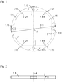
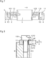
- the invention is based on a rotary encoder ( Figure 7 ), which is intended to detect an angular position between a scanning unit 1 according to the invention and a scale element 2 or a scale that can be rotated relative to an axis A.
- the scanning unit 1 has a metal frame 1.1 which, in the exemplary embodiment presented, is made from an aluminum alloy.
- the metal frame 1.1 has an almost circular outer contour and has a first dimension D11 orthogonal to the axis, which corresponds to the maximum outer diameter of the metal frame 1.1.
- the metal frame 1.1 is made of a flat plate with a thickness which corresponds to a second dimension T11 of the metal frame 1.1, cut out.
- the axis A is oriented orthogonally to the metal frame 1.1 or to the end faces of the metal frame 1.1.
- the metal frame 1.1 has an axially continuous first recess 1.11, so that the metal frame 1.1 therefore encloses the continuous first recess 1.11.
- the first recess 1.11 is naturally delimited by an inside I of the metal frame 1.1.
- the inside I of the metal frame 1.1 is oriented parallel to the axis A and surrounds the axis A.
- This inside I has four inwardly projecting elements 1.12 oriented radially towards the axis A, each of which has an edge 1.121 running parallel to the axis A.
- the inside I has no shoulder or projection which would not run over the entire second extension T11 or over the entire thickness of the metal frame 1.1.
- the continuous first recess 1.11 can therefore be produced, for example, by a punching process or a laser or water jet cutting process.
- the metal frame 1.1 also has second recesses 1.13, which are designed as fastening bores in the exemplary embodiment presented.
- the metal frame 1.1 accordingly has a disk-shaped or annular shape.
- the first dimension D11 is 17.5 times greater than the second dimension T11.
- Lines virtually parallel to the axis can be arranged on the inside I of the metal frame 1.1 or on the first recess 1.11. Each of these lines has the same distance from the axis A over the second extension T11.
- the scanning unit 1 also comprises a printed circuit board 1.2.
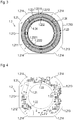
- the circuit board 1.2 is particularly in the Figures 3 and 4 shown. Accordingly, the printed circuit board 1.2 has a substrate 1.21 which, in the exemplary embodiment presented, has a plurality of layers.
- the substrate 1.21 has a first surface 1.211, and a second surface 1.212, the second surface 1.212 being arranged opposite to the first 1.211, as well as a circumferential third surface 1.213, which can also be referred to as a lateral surface.
- a pick-up arrangement 1.23 according to FIG Figure 3 arranged.
- the rotary encoder is based on an inductive scanning principle, so that the sensor arrangement 1.23 has two receiver tracks 1.231, 1.232, each of the receiver tracks 1.231, 1.232 comprising two receiver conductor tracks 1.2311, 1.2312, 1.2321, 1.2322.
- the receiver conductor tracks 1.2311, 1.2312, 1.2321, 1.2322 run on different levels with plated-through holes, so that undesired short circuits are avoided at crossing points.
- at least two layers are provided in the circuit board or substrate structure.
- the receiver conductor tracks 1.2311, 1.2312, 1.2321, 1.2322 have a spatially periodic course that is essentially sinusoidal or sinusoidal.
- Receiver conductor tracks 1.2311, 1.2312, 1.2321, 1.2322, which belong to the same receiver track 1.231, 1.232, are arranged offset relative to one another along the circumferential direction.
- adjacent receiver conductor tracks 1.2311, 1.2312, 1.2321, 1.2322 are offset from one another by 1/4 of the full sine period (by ⁇ / 2 or 90 ° along the first direction x).
- the receiver conductor tracks 1.2311, 1.2312, 1.2321, 1.2322 are electrically connected in such a way that they can ultimately deliver signals that are phase-shifted by 90 ° in the circumferential direction with regard to position determination.
- the scanning unit 1 comprises excitation conductor tracks 1.24, which are also arranged on the first surface 1.211 and enclose the receiver conductor tracks 1.2311, 1.2312, 1.2321, 1.2322.
- An electronic circuit is required to operate the excitation conductor tracks 1.24 and to process the signals received from the receiver conductor tracks 1.2311, 1.2312, 1.2321, 1.2322.
- an electrical coupling piece 1.221 for producing a plug connection with a mating connector of a cable is mounted on the second surface 1.212.
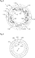
- the printed circuit board 1.2 has four concave indentations 1.214 on the jacket surface side, that is to say on its circumferential jacket side.
- the printed circuit board 1.2 or the substrate 1.21 is pressed into the metal frame 1.1 so that the edges 1.121 of the protruding elements 1.12 dig into the substrate 1.21 in the area of the indentations 1.214 ( Figure 5 ).
- the substrate 1.21 is therefore oversized at the contact points with the metal frame 1.1.
- the protruding elements 1.12 engage in the concave indentations 1.214 in such a way that the substrate 1.21 is fixed in the metal frame 1.1 under mechanical tension.
- the circuit board 1.2 with the sensor arrangement 1.23 is fixed exactly relative to the metal frame 1.1 or to the second recesses 1.13 in all spatial directions, which is important with regard to the measuring accuracy of the rotary encoder.
- the scale element 2 is shown in a top view.
- the scale element 2 consists of a substrate 2.3, which in the illustrated embodiment is made of epoxy resin and on which two graduation tracks 2.1, 2.2 are arranged.
- the graduation tracks 2.1, 2.2 are ring-shaped and are arranged concentrically with respect to the axis A with different diameters on the substrate.
- the two graduation tracks 2.1, 2.2 each consist of a periodic sequence of alternately arranged electrically conductive graduation areas 2.11, 2.21 and non-conductive graduation areas 2.12, 2.22.
- copper was applied to the material for the electrically conductive graduation areas 2.11, 2.21 Substrate 2.3 applied.
- the substrate 2.3 was not coated in the non-conductive graduation areas 2.12, 2.22.
- a rotary encoder which comprises the scanning unit 1 and the scale element 2.
- the scanning unit 1 is fixed to a first machine part 4, here a flange, with the aid of fastening elements 1.3 which, in the exemplary embodiment presented, are designed as screws.
- the fastening elements 1.3 are inserted through the second recesses 1.13 so that they penetrate the second recesses 1.13.
- the fastening elements 1.3 each have a section 1.31 which protrudes inwardly beyond the substrate 1.21 and which is the head of the screw in the exemplary embodiment presented.
- the protruding section 1.31 projects beyond the substrate 1.21 over a length X1.
- the fastening elements 1.3 thus press the metal frame 1.1 against the flange 4 and at the same time secure the circuit board 1.2 in the axial direction.
- the circuit board 1.2 or the substrate 1.21 was pressed into the metal frame 1.1 in the course of the assembly of the scanning unit 1 in the direction of the axis A so that the metal frame 1.1 has a first axial protrusion H1 with respect to the first surface 1.211 of the substrate 1.21.
- the first surface 1.211 of the substrate 1.21 is that side of the printed circuit board 1.2 on which the sensor arrangement 1.23 and the excitation conductor tracks 1.24 are arranged.
- the first axial projection H1 relates to the end face of the metal frame and the first face 1.211 of the substrate 1.21.
- the circuit board 1.2 is arranged in the metal frame 1.1 in such a way that the metal frame 1.1 has a second axial projection H2 with respect to the second surface 1.212 of the substrate 1.21.
- the metal frame 1.1 thus has a larger second dimension T11 in the direction of the axis A than the substrate 1.21, which has a third dimension T121 in the direction of the axis A.
- the substrate 1.21 is therefore complete surrounded by the metal frame 1.1 or by the inside I of the metal frame 1.1 and does not protrude axially at any point beyond the outer contour of the metal frame 1.1.
- the scanning unit 1 and the scale element 2 face one another with an axial distance C or an axial air gap.
- the axial protrusion H1 can be set easily but very precisely during assembly, for example by means of suitable assembly devices with stops, so that the desired distance C can also be easily set with a high degree of accuracy. This increases the measuring accuracy of the encoder.
- the excitation conductor tracks 1.24 generate a time-changing electromagnetic excitation field in the area of the scanned graduation structures.
- the excitation conductor tracks 1.24 are designed as a plurality of planar-parallel, current-carrying individual conductor tracks.
- the electronic circuit of the scanning unit 1 with the electronic components 1.22 works not only as an evaluation element, but also as an excitation control element, under whose control the excitation current is generated, which then flows through the excitation conductor tracks 1.24.
- a tubular or cylindrical electromagnetic field is formed around the respective excitation conductor track 1.24.
- the field lines of the resulting electromagnetic field run in the form of concentric circles around the exciter conductor tracks 1.24, the direction of the field lines depending in a known manner on the direction of current in the exciter conductor tracks 1.24.
- Eddy currents are induced in the area of the electrically conductive graduation areas 2.11, 2.21, so that a modulation of the field dependent on the angular position is achieved.
- the relative angular position can be measured in relation to axis A as the axis of rotation.
- the pairs of receiver conductor tracks 1.2311, 1.2312, 1.2321, 1.2322 are arranged within their receiver track 1.231, 1.232 in such a way that they each deliver signals that are 90 ° out of phase so that the direction of rotation can also be determined.
Landscapes
- Physics & Mathematics (AREA)
- General Physics & Mathematics (AREA)
- Transmission And Conversion Of Sensor Element Output (AREA)
Priority Applications (5)
| Application Number | Priority Date | Filing Date | Title |
|---|---|---|---|
| EP20181310.2A EP3929539B1 (fr) | 2020-06-22 | 2020-06-22 | Unité de détection et capteur rotatif équipé d'une telle unité de détection |
| DE102021200441.5A DE102021200441A1 (de) | 2020-06-22 | 2021-01-19 | Abtasteinheit und damit ausgestatteter drehgeber |
| JP2021012763A JP7550668B2 (ja) | 2020-06-22 | 2021-01-29 | 走査ユニットおよびこれを搭載したロータリエンコーダ |
| CN202110656792.8A CN113899389B (zh) | 2020-06-22 | 2021-06-11 | 扫描单元和装备有该扫描单元的旋转编码器 |
| US17/348,196 US11506516B2 (en) | 2020-06-22 | 2021-06-15 | Scanning unit and rotary encoder equipped therewith |
Applications Claiming Priority (1)
| Application Number | Priority Date | Filing Date | Title |
|---|---|---|---|
| EP20181310.2A EP3929539B1 (fr) | 2020-06-22 | 2020-06-22 | Unité de détection et capteur rotatif équipé d'une telle unité de détection |
Publications (2)
| Publication Number | Publication Date |
|---|---|
| EP3929539A1 true EP3929539A1 (fr) | 2021-12-29 |
| EP3929539B1 EP3929539B1 (fr) | 2022-08-24 |
Family
ID=71120035
Family Applications (1)
| Application Number | Title | Priority Date | Filing Date |
|---|---|---|---|
| EP20181310.2A Active EP3929539B1 (fr) | 2020-06-22 | 2020-06-22 | Unité de détection et capteur rotatif équipé d'une telle unité de détection |
Country Status (5)
| Country | Link |
|---|---|
| US (1) | US11506516B2 (fr) |
| EP (1) | EP3929539B1 (fr) |
| JP (1) | JP7550668B2 (fr) |
| CN (1) | CN113899389B (fr) |
| DE (1) | DE102021200441A1 (fr) |
Cited By (1)
| Publication number | Priority date | Publication date | Assignee | Title |
|---|---|---|---|---|
| EP4421454A1 (fr) | 2023-02-23 | 2024-08-28 | Dr. Johannes Heidenhain GmbH | Élément d'échelle pour un dispositif inductif de mesure de position |
Families Citing this family (1)
| Publication number | Priority date | Publication date | Assignee | Title |
|---|---|---|---|---|
| DE102020214235A1 (de) * | 2020-11-12 | 2022-05-12 | Robert Bosch Gesellschaft mit beschränkter Haftung | Induktive Positionssensoreinrichtung, Antriebseinrichtung |
Citations (5)
| Publication number | Priority date | Publication date | Assignee | Title |
|---|---|---|---|---|
| DE102007014781B3 (de) * | 2007-03-28 | 2008-05-15 | Bühler Motor GmbH | Encoderanordnung eines Gleichstrommotors |
| EP2674764A1 (fr) * | 2012-06-13 | 2013-12-18 | Aktiebolaget SKF | Procédé de production d'une unité de détection, unité de capteur et roulement instrumenté comprenant une telle unité de détection |
| US20180375405A1 (en) * | 2017-06-23 | 2018-12-27 | Nidec Sankyo Corporation | Motor |
| EP3505258A1 (fr) * | 2018-01-02 | 2019-07-03 | Sigma Laborzentrifugen GmbH | Centrifugeuse de laboratoire |
| DE102018202239A1 (de) | 2018-02-14 | 2019-08-14 | Dr. Johannes Heidenhain Gmbh | Lagerlose Winkelmesseinrichtung |
Family Cites Families (10)
| Publication number | Priority date | Publication date | Assignee | Title |
|---|---|---|---|---|
| US5084791A (en) * | 1988-05-10 | 1992-01-28 | Quantum Corporation | Head position control system for fixed drive including position encoder, temperature sensor and embedded fine servo information |
| DE102006026543B4 (de) * | 2006-06-07 | 2010-02-04 | Vogt Electronic Components Gmbh | Lagegeber und zugehöriges Verfahren zum Erfassen einer Position eines Läufers einer Maschine |
| JP5518766B2 (ja) | 2011-03-02 | 2014-06-11 | 愛三工業株式会社 | 検出ロータ、回転検出器及びその取付構造 |
| TWI638241B (zh) * | 2012-03-26 | 2018-10-11 | 日商尼康股份有限公司 | 基板處理裝置、處理裝置及元件製造方法 |
| JP6003392B2 (ja) * | 2012-06-29 | 2016-10-05 | 日本精工株式会社 | 取付板付転がり軸受ユニットとその製造方法 |
| DE102016101965A1 (de) * | 2016-02-04 | 2017-08-10 | Fraba B.V. | Verfahren zum Kalibrieren eines Drehgebers und Drehgeber zur Bestimmung einer korrigierten Winkelposition |
| JP2018179903A (ja) | 2017-04-20 | 2018-11-15 | 株式会社ニコン | エンコーダ装置、駆動装置、ステージ装置、及びロボット装置 |
| DE102017123681C5 (de) * | 2017-10-11 | 2022-01-27 | Leitz Gmbh & Co. Kg | Fräswerkzeug zum Bearbeiten von Holz, Holzwerkstoffen, Kunststoffen oder Leichtmetallen |
| US11340336B2 (en) * | 2017-12-07 | 2022-05-24 | Ouster, Inc. | Rotating light ranging system with optical communication uplink and downlink channels |
| EP3534121B1 (fr) * | 2018-03-02 | 2021-01-27 | Dr. Johannes Heidenhain GmbH | Capteur de rotation multitour |
-
2020
- 2020-06-22 EP EP20181310.2A patent/EP3929539B1/fr active Active
-
2021
- 2021-01-19 DE DE102021200441.5A patent/DE102021200441A1/de not_active Withdrawn
- 2021-01-29 JP JP2021012763A patent/JP7550668B2/ja active Active
- 2021-06-11 CN CN202110656792.8A patent/CN113899389B/zh active Active
- 2021-06-15 US US17/348,196 patent/US11506516B2/en active Active
Patent Citations (5)
| Publication number | Priority date | Publication date | Assignee | Title |
|---|---|---|---|---|
| DE102007014781B3 (de) * | 2007-03-28 | 2008-05-15 | Bühler Motor GmbH | Encoderanordnung eines Gleichstrommotors |
| EP2674764A1 (fr) * | 2012-06-13 | 2013-12-18 | Aktiebolaget SKF | Procédé de production d'une unité de détection, unité de capteur et roulement instrumenté comprenant une telle unité de détection |
| US20180375405A1 (en) * | 2017-06-23 | 2018-12-27 | Nidec Sankyo Corporation | Motor |
| EP3505258A1 (fr) * | 2018-01-02 | 2019-07-03 | Sigma Laborzentrifugen GmbH | Centrifugeuse de laboratoire |
| DE102018202239A1 (de) | 2018-02-14 | 2019-08-14 | Dr. Johannes Heidenhain Gmbh | Lagerlose Winkelmesseinrichtung |
Cited By (2)
| Publication number | Priority date | Publication date | Assignee | Title |
|---|---|---|---|---|
| EP4421454A1 (fr) | 2023-02-23 | 2024-08-28 | Dr. Johannes Heidenhain GmbH | Élément d'échelle pour un dispositif inductif de mesure de position |
| DE102024000091A1 (de) | 2023-02-23 | 2024-08-29 | Dr. Johannes Heidenhain Gmbh | Skalenelement für eine induktive positionsmesseinrichtung |
Also Published As
| Publication number | Publication date |
|---|---|
| US20210396552A1 (en) | 2021-12-23 |
| US11506516B2 (en) | 2022-11-22 |
| EP3929539B1 (fr) | 2022-08-24 |
| CN113899389B (zh) | 2025-09-16 |
| CN113899389A (zh) | 2022-01-07 |
| JP2022001860A (ja) | 2022-01-06 |
| DE102021200441A1 (de) | 2021-12-23 |
| JP7550668B2 (ja) | 2024-09-13 |
Similar Documents
| Publication | Publication Date | Title |
|---|---|---|
| EP3355032B1 (fr) | Capteur de mesure de position | |
| EP2743649B1 (fr) | Dispositif de mesure de position inductif | |
| EP4174443B1 (fr) | Dispositif inductif de mesure d'angle | |
| EP3961158B1 (fr) | Unité de balayage et dispositif inductif de mesure de position pourvu d'une telle unité de balayage | |
| EP3495781B1 (fr) | Dispositif inductif de mesure de position | |
| EP3534121B1 (fr) | Capteur de rotation multitour | |
| EP4012351B1 (fr) | Élément de dètection et dispositif de mesure de position inductif pourvu dudit élément de détection | |
| EP1927823B1 (fr) | Encodeur | |
| EP1927824B1 (fr) | Encodeur | |
| EP4012350B1 (fr) | Élément de détection et dispositif de mesure de position inductif pourvu dudit élément de détection | |
| EP3702737B1 (fr) | Unité de balayage permettant de balayer une échelle d'angle ainsi que dispositif de mesure d'angle doté d'une telle unité de balayage | |
| EP3929539B1 (fr) | Unité de détection et capteur rotatif équipé d'une telle unité de détection | |
| EP3904836A1 (fr) | Dispositif inductif de mesure de position | |
| EP3683552B1 (fr) | Unité de balayage pour un dispositif de mesure d'angle | |
| EP3399284A1 (fr) | Capteur de mesure de position | |
| EP4230967B1 (fr) | Élément palpeur et dispositif inductif de mesure de position pourvu dudit élément palpeur | |
| EP4273507A1 (fr) | Élément de détection et dispositif inductif de mesure de position pourvu dudit élément palpeur | |
| EP4336148B1 (fr) | Élément de balayage et dispositif de mesure de position inductif comprenant ledit élément de balayage | |
| EP4421454B1 (fr) | Élément d'échelle pour un dispositif inductif de mesure de position | |
| EP4086584B1 (fr) | Module doté d'un capteur rotatif et d'un manchon de tolérance | |
| EP4647726A1 (fr) | Dispositif de mesure de position | |
| EP3657133A1 (fr) | Unité de capteur et dispositif de mesure de position doté d'une telle unité de capteur |
Legal Events
| Date | Code | Title | Description |
|---|---|---|---|
| PUAI | Public reference made under article 153(3) epc to a published international application that has entered the european phase |
Free format text: ORIGINAL CODE: 0009012 |
|
| STAA | Information on the status of an ep patent application or granted ep patent |
Free format text: STATUS: REQUEST FOR EXAMINATION WAS MADE |
|
| 17P | Request for examination filed |
Effective date: 20200622 |
|
| AK | Designated contracting states |
Kind code of ref document: A1 Designated state(s): AL AT BE BG CH CY CZ DE DK EE ES FI FR GB GR HR HU IE IS IT LI LT LU LV MC MK MT NL NO PL PT RO RS SE SI SK SM TR |
|
| B565 | Issuance of search results under rule 164(2) epc |
Effective date: 20201130 |
|
| GRAP | Despatch of communication of intention to grant a patent |
Free format text: ORIGINAL CODE: EPIDOSNIGR1 |
|
| STAA | Information on the status of an ep patent application or granted ep patent |
Free format text: STATUS: GRANT OF PATENT IS INTENDED |
|
| RIC1 | Information provided on ipc code assigned before grant |
Ipc: G01D 5/20 20060101ALN20220420BHEP Ipc: G01D 11/24 20060101ALI20220420BHEP Ipc: G01D 5/244 20060101AFI20220420BHEP |
|
| INTG | Intention to grant announced |
Effective date: 20220510 |
|
| GRAS | Grant fee paid |
Free format text: ORIGINAL CODE: EPIDOSNIGR3 |
|
| GRAA | (expected) grant |
Free format text: ORIGINAL CODE: 0009210 |
|
| STAA | Information on the status of an ep patent application or granted ep patent |
Free format text: STATUS: THE PATENT HAS BEEN GRANTED |
|
| RBV | Designated contracting states (corrected) |
Designated state(s): AL AT BE BG CH CY CZ DE DK EE ES FI FR GB GR HR HU IE IS IT LI LT LU LV MC MK MT NL NO PL PT RO RS SE SI SK SM TR |
|
| AK | Designated contracting states |
Kind code of ref document: B1 Designated state(s): AL AT BE BG CH CY CZ DE DK EE ES FI FR GB GR HR HU IE IS IT LI LT LU LV MC MK MT NL NO PL PT RO RS SE SI SK SM TR |
|
| REG | Reference to a national code |
Ref country code: CH Ref legal event code: EP |
|
| REG | Reference to a national code |
Ref country code: IE Ref legal event code: FG4D Free format text: LANGUAGE OF EP DOCUMENT: GERMAN |
|
| REG | Reference to a national code |
Ref country code: AT Ref legal event code: REF Ref document number: 1513950 Country of ref document: AT Kind code of ref document: T Effective date: 20220915 Ref country code: DE Ref legal event code: R096 Ref document number: 502020001568 Country of ref document: DE |
|
| REG | Reference to a national code |
Ref country code: LT Ref legal event code: MG9D |
|
| REG | Reference to a national code |
Ref country code: NL Ref legal event code: MP Effective date: 20220824 |
|
| PG25 | Lapsed in a contracting state [announced via postgrant information from national office to epo] |
Ref country code: SE Free format text: LAPSE BECAUSE OF FAILURE TO SUBMIT A TRANSLATION OF THE DESCRIPTION OR TO PAY THE FEE WITHIN THE PRESCRIBED TIME-LIMIT Effective date: 20220824 Ref country code: RS Free format text: LAPSE BECAUSE OF FAILURE TO SUBMIT A TRANSLATION OF THE DESCRIPTION OR TO PAY THE FEE WITHIN THE PRESCRIBED TIME-LIMIT Effective date: 20220824 Ref country code: PT Free format text: LAPSE BECAUSE OF FAILURE TO SUBMIT A TRANSLATION OF THE DESCRIPTION OR TO PAY THE FEE WITHIN THE PRESCRIBED TIME-LIMIT Effective date: 20221226 Ref country code: NO Free format text: LAPSE BECAUSE OF FAILURE TO SUBMIT A TRANSLATION OF THE DESCRIPTION OR TO PAY THE FEE WITHIN THE PRESCRIBED TIME-LIMIT Effective date: 20221124 Ref country code: NL Free format text: LAPSE BECAUSE OF FAILURE TO SUBMIT A TRANSLATION OF THE DESCRIPTION OR TO PAY THE FEE WITHIN THE PRESCRIBED TIME-LIMIT Effective date: 20220824 Ref country code: LV Free format text: LAPSE BECAUSE OF FAILURE TO SUBMIT A TRANSLATION OF THE DESCRIPTION OR TO PAY THE FEE WITHIN THE PRESCRIBED TIME-LIMIT Effective date: 20220824 Ref country code: LT Free format text: LAPSE BECAUSE OF FAILURE TO SUBMIT A TRANSLATION OF THE DESCRIPTION OR TO PAY THE FEE WITHIN THE PRESCRIBED TIME-LIMIT Effective date: 20220824 Ref country code: FI Free format text: LAPSE BECAUSE OF FAILURE TO SUBMIT A TRANSLATION OF THE DESCRIPTION OR TO PAY THE FEE WITHIN THE PRESCRIBED TIME-LIMIT Effective date: 20220824 |
|
| PG25 | Lapsed in a contracting state [announced via postgrant information from national office to epo] |
Ref country code: PL Free format text: LAPSE BECAUSE OF FAILURE TO SUBMIT A TRANSLATION OF THE DESCRIPTION OR TO PAY THE FEE WITHIN THE PRESCRIBED TIME-LIMIT Effective date: 20220824 Ref country code: IS Free format text: LAPSE BECAUSE OF FAILURE TO SUBMIT A TRANSLATION OF THE DESCRIPTION OR TO PAY THE FEE WITHIN THE PRESCRIBED TIME-LIMIT Effective date: 20221224 Ref country code: HR Free format text: LAPSE BECAUSE OF FAILURE TO SUBMIT A TRANSLATION OF THE DESCRIPTION OR TO PAY THE FEE WITHIN THE PRESCRIBED TIME-LIMIT Effective date: 20220824 Ref country code: GR Free format text: LAPSE BECAUSE OF FAILURE TO SUBMIT A TRANSLATION OF THE DESCRIPTION OR TO PAY THE FEE WITHIN THE PRESCRIBED TIME-LIMIT Effective date: 20221125 |
|
| PG25 | Lapsed in a contracting state [announced via postgrant information from national office to epo] |
Ref country code: SM Free format text: LAPSE BECAUSE OF FAILURE TO SUBMIT A TRANSLATION OF THE DESCRIPTION OR TO PAY THE FEE WITHIN THE PRESCRIBED TIME-LIMIT Effective date: 20220824 Ref country code: RO Free format text: LAPSE BECAUSE OF FAILURE TO SUBMIT A TRANSLATION OF THE DESCRIPTION OR TO PAY THE FEE WITHIN THE PRESCRIBED TIME-LIMIT Effective date: 20220824 Ref country code: ES Free format text: LAPSE BECAUSE OF FAILURE TO SUBMIT A TRANSLATION OF THE DESCRIPTION OR TO PAY THE FEE WITHIN THE PRESCRIBED TIME-LIMIT Effective date: 20220824 Ref country code: DK Free format text: LAPSE BECAUSE OF FAILURE TO SUBMIT A TRANSLATION OF THE DESCRIPTION OR TO PAY THE FEE WITHIN THE PRESCRIBED TIME-LIMIT Effective date: 20220824 |
|
| REG | Reference to a national code |
Ref country code: DE Ref legal event code: R097 Ref document number: 502020001568 Country of ref document: DE |
|
| PG25 | Lapsed in a contracting state [announced via postgrant information from national office to epo] |
Ref country code: SK Free format text: LAPSE BECAUSE OF FAILURE TO SUBMIT A TRANSLATION OF THE DESCRIPTION OR TO PAY THE FEE WITHIN THE PRESCRIBED TIME-LIMIT Effective date: 20220824 Ref country code: EE Free format text: LAPSE BECAUSE OF FAILURE TO SUBMIT A TRANSLATION OF THE DESCRIPTION OR TO PAY THE FEE WITHIN THE PRESCRIBED TIME-LIMIT Effective date: 20220824 |
|
| PG25 | Lapsed in a contracting state [announced via postgrant information from national office to epo] |
Ref country code: AL Free format text: LAPSE BECAUSE OF FAILURE TO SUBMIT A TRANSLATION OF THE DESCRIPTION OR TO PAY THE FEE WITHIN THE PRESCRIBED TIME-LIMIT Effective date: 20220824 |
|
| PLBE | No opposition filed within time limit |
Free format text: ORIGINAL CODE: 0009261 |
|
| STAA | Information on the status of an ep patent application or granted ep patent |
Free format text: STATUS: NO OPPOSITION FILED WITHIN TIME LIMIT |
|
| 26N | No opposition filed |
Effective date: 20230525 |
|
| PG25 | Lapsed in a contracting state [announced via postgrant information from national office to epo] |
Ref country code: MC Free format text: LAPSE BECAUSE OF FAILURE TO SUBMIT A TRANSLATION OF THE DESCRIPTION OR TO PAY THE FEE WITHIN THE PRESCRIBED TIME-LIMIT Effective date: 20220824 |
|
| PG25 | Lapsed in a contracting state [announced via postgrant information from national office to epo] |
Ref country code: MC Free format text: LAPSE BECAUSE OF FAILURE TO SUBMIT A TRANSLATION OF THE DESCRIPTION OR TO PAY THE FEE WITHIN THE PRESCRIBED TIME-LIMIT Effective date: 20220824 |
|
| REG | Reference to a national code |
Ref country code: BE Ref legal event code: MM Effective date: 20230630 |
|
| PG25 | Lapsed in a contracting state [announced via postgrant information from national office to epo] |
Ref country code: LU Free format text: LAPSE BECAUSE OF NON-PAYMENT OF DUE FEES Effective date: 20230622 |
|
| REG | Reference to a national code |
Ref country code: IE Ref legal event code: MM4A |
|
| PG25 | Lapsed in a contracting state [announced via postgrant information from national office to epo] |
Ref country code: LU Free format text: LAPSE BECAUSE OF NON-PAYMENT OF DUE FEES Effective date: 20230622 |
|
| PG25 | Lapsed in a contracting state [announced via postgrant information from national office to epo] |
Ref country code: IE Free format text: LAPSE BECAUSE OF NON-PAYMENT OF DUE FEES Effective date: 20230622 |
|
| PG25 | Lapsed in a contracting state [announced via postgrant information from national office to epo] |
Ref country code: IE Free format text: LAPSE BECAUSE OF NON-PAYMENT OF DUE FEES Effective date: 20230622 |
|
| PG25 | Lapsed in a contracting state [announced via postgrant information from national office to epo] |
Ref country code: FR Free format text: LAPSE BECAUSE OF NON-PAYMENT OF DUE FEES Effective date: 20230630 Ref country code: BE Free format text: LAPSE BECAUSE OF NON-PAYMENT OF DUE FEES Effective date: 20230630 |
|
| PG25 | Lapsed in a contracting state [announced via postgrant information from national office to epo] |
Ref country code: BG Free format text: LAPSE BECAUSE OF FAILURE TO SUBMIT A TRANSLATION OF THE DESCRIPTION OR TO PAY THE FEE WITHIN THE PRESCRIBED TIME-LIMIT Effective date: 20220824 |
|
| PG25 | Lapsed in a contracting state [announced via postgrant information from national office to epo] |
Ref country code: BG Free format text: LAPSE BECAUSE OF FAILURE TO SUBMIT A TRANSLATION OF THE DESCRIPTION OR TO PAY THE FEE WITHIN THE PRESCRIBED TIME-LIMIT Effective date: 20220824 |
|
| PGFP | Annual fee paid to national office [announced via postgrant information from national office to epo] |
Ref country code: DE Payment date: 20250618 Year of fee payment: 6 |
|
| PGFP | Annual fee paid to national office [announced via postgrant information from national office to epo] |
Ref country code: GB Payment date: 20250618 Year of fee payment: 6 |
|
| PGFP | Annual fee paid to national office [announced via postgrant information from national office to epo] |
Ref country code: AT Payment date: 20250721 Year of fee payment: 5 |
|
| PG25 | Lapsed in a contracting state [announced via postgrant information from national office to epo] |
Ref country code: CY Free format text: LAPSE BECAUSE OF FAILURE TO SUBMIT A TRANSLATION OF THE DESCRIPTION OR TO PAY THE FEE WITHIN THE PRESCRIBED TIME-LIMIT; INVALID AB INITIO Effective date: 20200622 |
|
| PGFP | Annual fee paid to national office [announced via postgrant information from national office to epo] |
Ref country code: CZ Payment date: 20250617 Year of fee payment: 6 |
|
| PG25 | Lapsed in a contracting state [announced via postgrant information from national office to epo] |
Ref country code: HU Free format text: LAPSE BECAUSE OF FAILURE TO SUBMIT A TRANSLATION OF THE DESCRIPTION OR TO PAY THE FEE WITHIN THE PRESCRIBED TIME-LIMIT; INVALID AB INITIO Effective date: 20200622 |
|
| PGFP | Annual fee paid to national office [announced via postgrant information from national office to epo] |
Ref country code: IT Payment date: 20250624 Year of fee payment: 6 |
|
| PGFP | Annual fee paid to national office [announced via postgrant information from national office to epo] |
Ref country code: CH Payment date: 20250701 Year of fee payment: 6 |
|
| PG25 | Lapsed in a contracting state [announced via postgrant information from national office to epo] |
Ref country code: TR Free format text: LAPSE BECAUSE OF FAILURE TO SUBMIT A TRANSLATION OF THE DESCRIPTION OR TO PAY THE FEE WITHIN THE PRESCRIBED TIME-LIMIT Effective date: 20220824 |
|
| REG | Reference to a national code |
Ref country code: CH Ref legal event code: R17 Free format text: ST27 STATUS EVENT CODE: U-0-0-R10-R17 (AS PROVIDED BY THE NATIONAL OFFICE) Effective date: 20260108 |
|
| PG25 | Lapsed in a contracting state [announced via postgrant information from national office to epo] |
Ref country code: SI Free format text: LAPSE BECAUSE OF FAILURE TO SUBMIT A TRANSLATION OF THE DESCRIPTION OR TO PAY THE FEE WITHIN THE PRESCRIBED TIME-LIMIT Effective date: 20220824 |