EP3929607B1 - Système de surveillance du courant de fuite d'un appareillage de commutation haute tension ou moyenne tension - Google Patents
Système de surveillance du courant de fuite d'un appareillage de commutation haute tension ou moyenne tension Download PDFInfo
- Publication number
- EP3929607B1 EP3929607B1 EP21183309.0A EP21183309A EP3929607B1 EP 3929607 B1 EP3929607 B1 EP 3929607B1 EP 21183309 A EP21183309 A EP 21183309A EP 3929607 B1 EP3929607 B1 EP 3929607B1
- Authority
- EP
- European Patent Office
- Prior art keywords
- leakage current
- electrode
- conducting layer
- switchgear
- current monitoring
- Prior art date
- Legal status (The legal status is an assumption and is not a legal conclusion. Google has not performed a legal analysis and makes no representation as to the accuracy of the status listed.)
- Active
Links
Images


Classifications
-
- G—PHYSICS
- G01—MEASURING; TESTING
- G01R—MEASURING ELECTRIC VARIABLES; MEASURING MAGNETIC VARIABLES
- G01R31/00—Arrangements for testing electric properties; Arrangements for locating electric faults; Arrangements for electrical testing characterised by what is being tested not provided for elsewhere
- G01R31/50—Testing of electric apparatus, lines, cables or components for short-circuits, continuity, leakage current or incorrect line connections
- G01R31/52—Testing for short-circuits, leakage current or ground faults
Definitions
- the present invention relates to a switchgear leakage current monitoring system for a high voltage or medium voltage switchgear.
- a High voltage or medium voltage switchgear that is exposed to air can suffer from a deposition of dust and suffer from the effects of humidity on the surface of its insulating components. This holds both for air insulated HV-switchgear and (depending on the environment and the climatic zone of the installation) and also for components in MV-switchgear cabinets, which cannot be completely sealed off from the environment.
- the deposition of dust and the effects of humidity on the surface of electrically stressed insulating components can lead to an increased surface conductivity on these insulators. This can give rise to leakage currents and dry-band arcing.
- US2014/176336A1 describes a system and method for real-time remotely (i.e., at least several miles away) monitoring MOV surge arresters conditions along with a method and circuitry for sensing the total leakage current of a surge arrester in a power grid.
- leakage current circuitry may include a MOV arrester leakage current sensing block having shunt circuitry formed using a biasing resistor, one or more optocouplers that isolate the radio module system from the MOV arrester stem line and monitors the total leakage current and other states of the primary stage, and a mini ZOV that acts as a surge protection device.
- the outputs of the optocouplers can be set up to provide a linear or digital output or both to a communications network, the communications network can transmit a signal corresponding to a fault state of a surge arrester to a remote central control center.
- an alternative and complementary way of monitoring MOV condition involves registering the time and counts of the lightning strikes with a renovated mechanical counter telemetry.
- the circuit may be powered by the MOV leakage current itself.
- a switchgear leakage current monitoring system for a high voltage or medium voltage switchgear as defined in appended claim 1.
- a switchgear leakage current monitoring system for a high voltage or medium voltage switchgear comprising:
- the at least one sensor comprises at least one conducting layer or electrode.
- Each sensor comprises a conducting layer or electrode.
- the at least one conducting layer or electrode is attached or integrated on at least one surface of at least one insulating component of a high voltage or medium voltage switchgear.
- Each insulating component has a conducting layer or electrode attached or integrated on its surface.
- the at least one sensor is configured to acquire at least one leakage current signal.
- Each sensor is configured to acquire a leakage current signal on a surface of the insulating component to which its corresponding conducting layer or electrode is attached or integrated.
- the at least sensor has at least one data connection to the leakage current monitoring unit.
- the leakage current monitoring unit is configured to be provided with at least one measurement data relating to the at least one leakage current signal via the at least one data connection.
- the at least one insulating component is mechanically attached to at least one electrically conductive part at ground potential of the high voltage or medium voltage switchgear.
- Each insulating component is mechanically attached to an electrically conductive part.
- the at least one conducting layer or electrode is situated at a corresponding at least one location of the at least one insulating component that is close to the at least one electrically conductive part such that the at least one conducting layer or electrode is not in direct contact with the at least one electrically conductive part.
- the leakage current detection parts of sensors are close to, but not in direct contact with electrically conductive parts of the switchgear to which the insulators are mounted.
- the at least one sensor comprises at least one connection connected to the at least one conducting layer or electrode.
- the at least one connection is close to the at least one electrically conductive part such that the at least one connection is not in direct contact with the at least one electrically conductive part.
- the at least one sensor comprises at least one ground connection.
- a ground potential reference can be provided to a measurement circuit.
- connection to a conducting layer or electrode and a ground connection of a sensor are located close to one another.
- a conducting layer or electrode of the at least one conducting layer or electrode is mechanically attached to an electrically conductive part of the at least one electrically conductive part to which a corresponding insulating component is mechanically attached.
- the conducting layer or electrode is isolated from the electrically conductive part by an insulating layer.
- the insulating layer is attached to the conducting layer or electrode.
- the insulating layer is attached to the electrically conductive part at ground potential.
- each conducting layer or electrode of the at least one conducting layer or electrode encircles the insulating component of the at least one insulating component to which it is attached or integrated.
- a conducting layer or electrode of the at least one conducting layer or electrode is integrated into a printed circuit board.
- a conducting layer or electrode of the at least one conducting layer or electrode is a metallic sheet, or glued foil, or wire.
- the at least one insulating component comprises one or more of: bushings; post insulators, insulation of contact plugs, insulating case of current transducer, insulating case of voltage transducers.
- the at least one data connection comprises at least one wired connection.
- a measurement circuit integrated into the leakage current monitoring unit comprises a low impedance shunt and a voltage meter.
- the at least one data connection comprises at least one wireless connection.
- a measurement unit is configured to provide one or more measurement data relating to the at least one leakage current wirelessly to the leakage current monitoring unit.
- the measurement unit is configured to be powered by leakage current it measures.
- Figs. 1-9 show detailed examples of a switchgear leakage current monitoring system 1 for a high voltage or medium voltage switchgear.
- the figures show examples of a switchgear leakage current monitoring system 1 for a high voltage or medium voltage switchgear.
- the switchgear leakage current monitoring system comprises at least one sensor 14, 16, 17, and a leakage current monitoring unit 22.
- the at least one sensor comprises at least one conducting layer or electrode 14.
- Each sensor comprises a conducting layer or electrode.
- the at least one conducting layer or electrode is attached or integrated on at least one surface of at least one insulating component 11 of a high voltage or medium voltage switchgear.
- Each insulating component has a conducting layer or electrode attached or integrated on its surface.
- the at least one sensor is configured to acquire at least one leakage current signal.
- Each sensor is configured to acquire a leakage current signal on a surface of the insulating component to which its corresponding conducting layer or electrode is attached or integrated.
- the at least sensor has at least one data connection 24 to the leakage current monitoring unit.
- the leakage current monitoring unit is configured to be provided with at least one measurement data relating to the at least one leakage current signal
- the at least one insulating component is mechanically attached to at least one electrically conductive part 12 at ground potential of the high voltage or medium voltage switchgear.
- Each insulating component is mechanically attached to an electrically conductive part.
- the at least one conducting layer or electrode is situated at a corresponding at least one location 23 of the at least one insulating component that is close to the at least one electrically conductive part. This means that the at least one conducting layer or electrode is not in direct contact with the at least one electrically conductive part.
- the at least one sensor comprises at least one connection 17 connected to the at least one conducting layer or electrode 14.
- the at least one connection is close to the at least one electrically conductive part such that the at least one connection is not in direct contact with the at least one electrically conductive part.
- the at least one sensor comprises at least one ground connection 16.
- a ground connection 16 of a sensor associated with an insulating component 11 is connected to the electrically conductive part 12 at ground potential to which the insulating component is mechanically attached.
- connection 17 to a conducting layer or electrode 14 and a ground connection 16 of a sensor are located close to one another.
- a conducting layer or electrode 14 of the at least one conducting layer or electrode 14 is mechanically attached to an electrically conductive part 12 of the at least one electrically conductive part 12 to which a corresponding insulating component 11 is mechanically attached.
- the conducting layer or electrode 14 is isolated from the electrically conductive part by an insulating layer 15.
- the insulating layer 15 is attached to the conducting layer or electrode 14.
- the insulating layer 15 is attached to the electrically conductive part 12 at ground potential.
- each conducting layer or electrode of the at least one conducting layer or electrode 14 encircles the insulating component of the at least one insulating component 11 to which it is attached or integrated.
- a conducting layer or electrode of the at least one conducting layer or electrode 14 is integrated into a printed circuit board 19.
- a conducting layer or electrode of the at least one conducting layer or electrode 14 is a metallic sheet, or glued foil, or wire.
- the at least one insulating component 11 comprises one or more of: bushings 29, post insulators, insulation of contact plugs 31, insulating case of current transducer 33, and insulating case of voltage transducers 32.
- the at least one data connection 24 comprises at least one wired connection 24.1.
- a measurement circuit 40 integrated into the leakage current monitoring unit 22 comprises a low impedance shunt 41 and a voltage meter 43.
- the at least one data connection 24 comprises at least one wireless connection 24.2.
- a measurement unit 44 is configured to provide one or more measurement data relating to the at least one leakage current wirelessly to the leakage current monitoring unit 22.
- the measurement unit 44 is configured to be powered by leakage current it measures.
- the switchgear leakage current monitoring system enables the local leakage currents on the surface of the individual insulating components 11 to be continuously monitored. This is now described in further detail using the example of medium voltage switchgear and with reference to Figs. 1-9 .
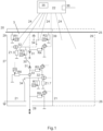
- the switchgear leakage current monitoring system 1 includes a central unit 22, which records a number of insulator leakage currents from one or more cubicles/sections 21 of the switchgear 20. It will transmit either the raw or processed data of the recorded leakage currents via a suitable interface and data connection 36 to a superordinate system, which will process and/or store the data for further analysis.
- the central unit 22 can also include a local indication of the leakage currents or of possible critical conditions (through for example an optical display 35 or acoustic signal).
- the central unit 22 can also perform a local analysis on the acquired leakage current signals. For example: a comparison with critical amplitudes or reference signals; a frequency analysis with an identification of critical frequency components; or the time-development of the leakage current amplitudes.
- the system may generate model-based information on the remaining component lifetimes and on the urgency and amount of required maintenance measures, such as surface cleaning or the necessary exchange of components, before any catastrophic failures will occur.
- the central unit 22 has data connections 24 to a number of measurement locations 23 that are situated on the surfaces of those insulating components 11 that shall be monitored.
- the measurement locations are close to but not in direct contact with electrically conducting parts 12 on ground potential, to which the insulators 11 are mechanically attached (for example, cubicle walls or mounting surfaces).
- the data connections 24 can be either based on wired (cable) connections or on any known or new wireless communication scheme.
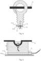
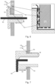
- Examples of insulating components 11 in the switchgear, on which surface leakage currents could be monitored include bushings 29, as shown in Fig. 6 , post insulators as shown in Fig. 3 , the insulation of contact plugs 31, as shown in Fig. 7 , as well as the insulating cases of current transducers/transformers 33 and voltage transducers/transformers 32 as shown in Figs. 4-5 .
- Fig. 1 shows where the respective leakage impedances R1 ... R8 would be typically located within a MV switchgear cubicle, and where suitable measurement locations 23 would be preferably established.
- the leakage currents When the leakage currents are not yet too large, they can be assumed to originate from ideal current sources (see Fig. 2 ), as the involved surface impedances are high. Therefore, the leakage current amplitudes will be largely independent on the input impedance of a connected measurement circuitry, if the latter is designed to be low enough. It is therefore sufficient, to attach a conducting pickup electrode or layer 14 to the surface of the insulator 11 at the respective measurement location 23, which shall be close to but not in direct electrical contact with conducting parts 12 at ground potential, to which the insulator 11 is mechanically attached. Ideally, this pickup electrode or layer 14 should completely encircle the region, where the insulator is in mechanical contact with the conducting part at ground potential in order to collect the injected leakage current to the largest possible extent.
- the pickup electrode or layer 14 is provided with a connection 17 for contacting to the input of the measurement circuit.
- Another connection 16 on a conducting part at ground potential 12 provides the reference to the measurement circuit.
- This connection may either be integrated with the insulating component, or, if no grounded metallic parts are available on this component, it may be integrated with the switchgear cubicle.
- Connections 16 and 17 are preferably located close to each other in order to avoid large ground loops. Placing electrode or layer 14 and connection 17 close to the conductor at ground potential also has the advantage that creeping distances on the surface of the insulator 11 are not significantly reduced. Examples of suitable configurations can be seen in Figs. 3 and 5 .
- the conducting pickup electrode or layer 14 is located on the surface area of the insulating component 11, where it is in mechanical contact with the conducting part at ground potential 12.
- the pickup layer or electrode 14 is electrically isolated from part 12 by an additional insulating layer 15, which is on top of layer 14. In this way, a reduction of surface creeping distances on the insulating component 11 can be completely avoided. Examples of such configurations can be seen in Figs. 6 and 7 .
- the stack of layers 14 and 15 can be also implemented as a double-sided printed circuit board 19, which can at the same time integrate connections 16 and 17, when the second copper-layer is put in contact with the conductor at ground potential. An example is shown in Fig. 4 .
- the pickup electrode or layer 14 is not integrated on a PCB, it can be realized as a metallic sheet, glued foil or wire, which is closely attached to the insulating body (e.g. during the casting process of the insulating component) in order to prevent leakage currents from bypassing underneath the metal.
- the electrode or layer can also consist of a conductive coating, like a metal or carbon filled resin, plastic or rubber, which could be spayed or printed onto the insulator surface.
- the respective measurement circuit 40 can be integrated into the central unit.
- the measurement circuit could be just composed of a low impedance shunt 41 and a voltage meter 43, which measures the voltage drop 42, that is caused across it by the leakage current 18.
- the current amplitude will be nearly independent of the shunt value, which can be adjusted to obtain a convenient voltage amplitude. This allows an accurate measurement of the leakage current. If an isolated measurement is required, voltage isolation can be provided by additional means like transformers or other common components.
- the measurement unit 44 will be preferably close to the insulating element. It may be even integrated with the device, e.g. mounted on its surface or molded into the insulating body.
- the advantage of such a configuration is that there are no cable connections to the central unit 22, which will reduce cost and installation work and increase the reliability of the system. These advantages will be even more significant, if the measurement unit 44 is self-supplied and does not need any batteries to power the electronics.
- Fig. 9 shows one possible example of such a solution. In this case, the leakage current will be rectified by a rectifier 45, and the rectified current will charge a capacitor 46.
- a discharge element 48 will suddenly become conductive and discharge the capacitor by delivering a current pulse to a wireless transmission unit 49.
- the discharge element can be a component or an electric circuit that exhibits a negative differential resistance above the said voltage level, like a reversely biased diode, a negative-glow lamp, etc.
- the transmission unit When the transmission unit is supplied by the current pulse, it will transmit its address (identifier) in a short wireless telegram to the central unit. The frequency of the telegrams with a specific identifier will thus indicate the amplitude of the respective leakage current. Transmission and receipt is via an appropriate antenna 50.
- the signal can be also digitized with an A/D-converter and transmitted based on a wireless protocol, while the low power electronics of the transmission unit is still powered from the leakage current.
Landscapes
- Physics & Mathematics (AREA)
- General Physics & Mathematics (AREA)
- Testing Of Short-Circuits, Discontinuities, Leakage, Or Incorrect Line Connections (AREA)
- Gas-Insulated Switchgears (AREA)
Claims (12)
- Système de surveillance de courant de fuite d'appareillage de commutation (1) pour un appareillage de commutation haute tension ou moyenne tension, comprenant :- au moins un capteur (14, 16, 17) ; et- une unité de surveillance de courant de fuite (22) ;dans lequel l'au moins un capteur comprend au moins une couche conductrice ou électrode (14), chaque capteur comprenant une couche conductrice ou électrode ;dans lequel l'au moins une couche conductrice ou électrode est attachée ou intégrée sur au moins une surface d'au moins un composant isolant (11) d'un appareillage de commutation haute tension ou moyenne tension, chaque composant isolant ayant une couche conductrice ou électrode attachée ou intégrée sur sa surface ;dans lequel l'au moins un capteur est configuré pour acquérir au moins un signal de courant de fuite, chaque capteur étant configuré pour acquérir un signal de courant de fuite sur une surface du composant isolant auquel sa couche conductrice ou électrode correspondante est attachée ou intégrée ;dans lequel l'au moins un capteur possède au moins une connexion de données (24) avec l'unité de surveillance de courant de fuite ;dans lequel l'unité de surveillance de courant de fuite est configurée pour recevoir au moins une donnée de mesure relative à l'au moins un signal de courant de fuite par le biais de l'au moins une connexion de données ; etdans lequel l'au moins une connexion de données comprend au moins une connexion sans fil (24.2), et dans lequel une unité de mesure (44) est configurée pour fournir une ou plusieurs données de mesure relatives à l'au moins un courant de fuite sans fil à l'unité de surveillance de courant de fuite (22), et dans lequel l'unité de mesure est configurée pour être alimentée par le courant de fuite qu'elle mesure.
- Système de surveillance de courant de fuite d'appareillage de commutation selon la revendication 1, dans lequel l'au moins un composant isolant est attaché mécaniquement à au moins une pièce électriquement conductrice (12) à un potentiel de terre de l'appareillage de commutation haute tension ou moyenne tension, dans lequel chaque composant isolant est attaché mécaniquement à une pièce électriquement conductrice, et dans lequel l'au moins une couche conductrice ou électrode est située à au moins un emplacement correspondant (23) de l'au moins un composant isolant qui est proche de l'au moins une pièce électriquement conductrice de telle sorte que l'au moins une couche conductrice ou électrode n'est pas en contact direct avec l'au moins une pièce électriquement conductrice.
- Système de surveillance de courant de fuite d'appareillage de commutation selon la revendication 2, dans lequel l'au moins un capteur comprend au moins une connexion (17) connectée à l'au moins une couche conductrice ou électrode, et dans lequel l'au moins une connexion est proche de l'au moins une pièce électriquement conductrice de telle sorte que l'au moins une connexion n'est pas en contact direct avec l'au moins une pièce électriquement conductrice.
- Système de surveillance de courant de fuite d'appareillage de commutation selon l'une quelconque des revendications 2 et 3, dans lequel l'au moins un capteur comprend au moins une connexion de terre (16).
- Système de surveillance de courant de fuite d'appareillage de commutation selon la revendication 4, dans lequel une connexion (17) à une couche conductrice ou électrode (14) et une connexion de terre (16) d'un capteur sont situées l'une près de l'autre.
- Système de surveillance de courant de fuite d'appareillage de commutation selon l'une quelconque des revendications 2 à 5, dans lequel une couche conductrice ou électrode (14) parmi l'au moins une couche conductrice ou électrode est attachée mécaniquement à une pièce électriquement conductrice (12) parmi l'au moins une pièce électriquement conductrice à laquelle un composant isolant correspondant est attaché mécaniquement, et dans lequel la couche conductrice ou électrode est isolée de la pièce électriquement conductrice par une couche isolante (15).
- Système de surveillance de courant de fuite d'appareillage de commutation selon la revendication 6, dans lequel la couche isolante (15) est attachée à la couche conductrice ou électrode (14).
- Système de surveillance de courant de fuite d'appareillage de commutation selon l'une quelconque des revendications 6 et 7, dans lequel la couche isolante (15) est attachée à la pièce électriquement conductrice (12) à un potentiel de terre.
- Système de surveillance de courant de fuite d'appareillage de commutation selon l'une quelconque des revendications 1 à 8, dans lequel chaque couche conductrice ou électrode parmi l'au moins une couche conductrice ou électrode (14) encercle le composant isolant parmi l'au moins un composant isolant (11) auquel elle est attachée ou intégrée.
- Système de surveillance de courant de fuite d'appareillage de commutation selon l'une quelconque des revendications 1 à 9, dans lequel une couche conductrice ou électrode parmi l'au moins une couche conductrice ou électrode (14) est intégrée à l'intérieur d'une carte de circuit imprimé (19).
- Système de surveillance de courant de fuite d'appareillage de commutation selon l'une quelconque des revendications 1 à 9, dans lequel une couche conductrice ou électrode parmi l'au moins une couche conductrice ou électrode (14) est une tôle métallique, ou une feuille collée, ou un fil.
- Système de surveillance de courant de fuite d'appareillage de commutation selon l'une quelconque des revendications 1 à 11, dans lequel l'au moins un composant isolant (11) comprend un ou plusieurs éléments parmi : des traversées (29), des supports isolants, une isolation de fiches de contact (31), un boîtier isolant de transducteur de courant (33), un boîtier isolant de transducteurs de tension (32).
Priority Applications (1)
| Application Number | Priority Date | Filing Date | Title |
|---|---|---|---|
| EP21183309.0A EP3929607B1 (fr) | 2018-12-11 | 2018-12-11 | Système de surveillance du courant de fuite d'un appareillage de commutation haute tension ou moyenne tension |
Applications Claiming Priority (2)
| Application Number | Priority Date | Filing Date | Title |
|---|---|---|---|
| EP21183309.0A EP3929607B1 (fr) | 2018-12-11 | 2018-12-11 | Système de surveillance du courant de fuite d'un appareillage de commutation haute tension ou moyenne tension |
| EP18211736.6A EP3667338B1 (fr) | 2018-12-11 | 2018-12-11 | Système de surveillance du courant de fuite d'un appareillage de commutation haute tension ou moyenne tension |
Related Parent Applications (2)
| Application Number | Title | Priority Date | Filing Date |
|---|---|---|---|
| EP18211736.6A Division EP3667338B1 (fr) | 2018-12-11 | 2018-12-11 | Système de surveillance du courant de fuite d'un appareillage de commutation haute tension ou moyenne tension |
| EP18211736.6A Division-Into EP3667338B1 (fr) | 2018-12-11 | 2018-12-11 | Système de surveillance du courant de fuite d'un appareillage de commutation haute tension ou moyenne tension |
Publications (2)
| Publication Number | Publication Date |
|---|---|
| EP3929607A1 EP3929607A1 (fr) | 2021-12-29 |
| EP3929607B1 true EP3929607B1 (fr) | 2024-08-14 |
Family
ID=64664923
Family Applications (2)
| Application Number | Title | Priority Date | Filing Date |
|---|---|---|---|
| EP21183309.0A Active EP3929607B1 (fr) | 2018-12-11 | 2018-12-11 | Système de surveillance du courant de fuite d'un appareillage de commutation haute tension ou moyenne tension |
| EP18211736.6A Active EP3667338B1 (fr) | 2018-12-11 | 2018-12-11 | Système de surveillance du courant de fuite d'un appareillage de commutation haute tension ou moyenne tension |
Family Applications After (1)
| Application Number | Title | Priority Date | Filing Date |
|---|---|---|---|
| EP18211736.6A Active EP3667338B1 (fr) | 2018-12-11 | 2018-12-11 | Système de surveillance du courant de fuite d'un appareillage de commutation haute tension ou moyenne tension |
Country Status (1)
| Country | Link |
|---|---|
| EP (2) | EP3929607B1 (fr) |
Families Citing this family (3)
| Publication number | Priority date | Publication date | Assignee | Title |
|---|---|---|---|---|
| CN111856327B (zh) * | 2020-08-24 | 2022-12-27 | 海南电网有限责任公司琼中供电局 | 一种漏电报警监测装置 |
| CN115864269A (zh) * | 2022-12-09 | 2023-03-28 | 江苏万奇电器集团(盱眙)有限公司 | 一种内置远程监控与预警装置的母线槽结构 |
| CN120314835B (zh) * | 2025-06-18 | 2025-08-29 | 云南海力特电气自动化有限公司 | 一种高压绝缘子泄漏电流在线监测系统及方法 |
Family Cites Families (5)
| Publication number | Priority date | Publication date | Assignee | Title |
|---|---|---|---|---|
| US5574378A (en) * | 1994-12-15 | 1996-11-12 | Square D Company | Insulation monitoring system for insulated high voltage apparatus |
| JP3757508B2 (ja) * | 1996-12-26 | 2006-03-22 | 日新電機株式会社 | 碍子汚損状態監視装置 |
| US6633169B1 (en) * | 1999-04-08 | 2003-10-14 | Doble Engineering Company | Monitoring leakage currents from high-voltage devices |
| US20140176336A1 (en) * | 2012-12-21 | 2014-06-26 | eLuminon, LLC. | System, method, and apparatus for remotely monitoring surge arrester conditions |
| US10161987B2 (en) * | 2014-09-29 | 2018-12-25 | Mitsubishi Electric Corporation | Insulation degradation monitoring device |
-
2018
- 2018-12-11 EP EP21183309.0A patent/EP3929607B1/fr active Active
- 2018-12-11 EP EP18211736.6A patent/EP3667338B1/fr active Active
Also Published As
| Publication number | Publication date |
|---|---|
| EP3667338A1 (fr) | 2020-06-17 |
| EP3667338B1 (fr) | 2021-08-18 |
| EP3929607A1 (fr) | 2021-12-29 |
Similar Documents
| Publication | Publication Date | Title |
|---|---|---|
| US10627431B2 (en) | Combined in-line DC and AC current sensor for high voltage electric power lines | |
| US9261549B2 (en) | Leakage current sensor for suspension type insulator | |
| US3991367A (en) | Detection of potential on high-voltage transmission lines | |
| US9535105B2 (en) | Apparatus and method for measuring leakage currents on porcelain and glass insulator disc strings | |
| CA2772219C (fr) | Procede et appareil pour la protection de systemes electriques contre des impulsions electromagnetiques extraordinaires | |
| EP2807493B1 (fr) | Détecteur de courant de fuite pour isolateur rigide à socle | |
| WO2014204819A1 (fr) | Surveillance sécurisée de traversées haute tension | |
| EA031555B1 (ru) | Модуль реактивного сопротивления линии питания и его применения | |
| EP3929607B1 (fr) | Système de surveillance du courant de fuite d'un appareillage de commutation haute tension ou moyenne tension | |
| WO2019194754A1 (fr) | Boîte de connexions comprenant un diviseur de tension de type isolant intégré et un capteur de décharge partielle inductif | |
| US20080174320A1 (en) | Partial discharge sensor and partial discharge monitoring system utilizing current sensors | |
| WO2013098226A1 (fr) | Transformateur combiné pour système d'alimentation | |
| CN113574757A (zh) | 闪电电流引出设备 | |
| WO2019229694A1 (fr) | Capteur de tension | |
| CN209088403U (zh) | 气体绝缘金属封闭开关设备及带电检测功能的盘式绝缘子 | |
| JP2007024707A (ja) | クランプメータによる漏れ電流測定、監視装置 | |
| KR102872860B1 (ko) | 전자식 전압 센서 | |
| CN219123700U (zh) | 用于开关柜的漏电监控设备以及开关柜 | |
| Vom Bögel et al. | Digitization of the Distribution Grid to Support e-Mobility Charging Infrastructure | |
| WO2024213957A1 (fr) | Fiche d'isolation à capteur | |
| JPH0470568A (ja) | サージ電圧センサ | |
| JPH01234016A (ja) | ガス絶縁機器の異常位置標定システム | |
| US20220165521A1 (en) | Disconnector device with passive radio device, grid protection system having the disconnector device, and method for indicating a state of the disconnector device | |
| JP3321479B2 (ja) | 故障点標定システム | |
| MXPA96003421A (en) | Monitoring system for high voltage appliance isolates |
Legal Events
| Date | Code | Title | Description |
|---|---|---|---|
| PUAI | Public reference made under article 153(3) epc to a published international application that has entered the european phase |
Free format text: ORIGINAL CODE: 0009012 |
|
| STAA | Information on the status of an ep patent application or granted ep patent |
Free format text: STATUS: THE APPLICATION HAS BEEN PUBLISHED |
|
| AC | Divisional application: reference to earlier application |
Ref document number: 3667338 Country of ref document: EP Kind code of ref document: P |
|
| AK | Designated contracting states |
Kind code of ref document: A1 Designated state(s): AL AT BE BG CH CY CZ DE DK EE ES FI FR GB GR HR HU IE IS IT LI LT LU LV MC MK MT NL NO PL PT RO RS SE SI SK SM TR |
|
| B565 | Issuance of search results under rule 164(2) epc |
Effective date: 20211126 |
|
| STAA | Information on the status of an ep patent application or granted ep patent |
Free format text: STATUS: REQUEST FOR EXAMINATION WAS MADE |
|
| 17P | Request for examination filed |
Effective date: 20220523 |
|
| RBV | Designated contracting states (corrected) |
Designated state(s): AL AT BE BG CH CY CZ DE DK EE ES FI FR GB GR HR HU IE IS IT LI LT LU LV MC MK MT NL NO PL PT RO RS SE SI SK SM TR |
|
| GRAP | Despatch of communication of intention to grant a patent |
Free format text: ORIGINAL CODE: EPIDOSNIGR1 |
|
| STAA | Information on the status of an ep patent application or granted ep patent |
Free format text: STATUS: GRANT OF PATENT IS INTENDED |
|
| INTG | Intention to grant announced |
Effective date: 20240105 |
|
| GRAJ | Information related to disapproval of communication of intention to grant by the applicant or resumption of examination proceedings by the epo deleted |
Free format text: ORIGINAL CODE: EPIDOSDIGR1 |
|
| STAA | Information on the status of an ep patent application or granted ep patent |
Free format text: STATUS: REQUEST FOR EXAMINATION WAS MADE |
|
| GRAP | Despatch of communication of intention to grant a patent |
Free format text: ORIGINAL CODE: EPIDOSNIGR1 |
|
| STAA | Information on the status of an ep patent application or granted ep patent |
Free format text: STATUS: GRANT OF PATENT IS INTENDED |
|
| INTC | Intention to grant announced (deleted) | ||
| INTG | Intention to grant announced |
Effective date: 20240411 |
|
| GRAS | Grant fee paid |
Free format text: ORIGINAL CODE: EPIDOSNIGR3 |
|
| GRAA | (expected) grant |
Free format text: ORIGINAL CODE: 0009210 |
|
| STAA | Information on the status of an ep patent application or granted ep patent |
Free format text: STATUS: THE PATENT HAS BEEN GRANTED |
|
| AC | Divisional application: reference to earlier application |
Ref document number: 3667338 Country of ref document: EP Kind code of ref document: P |
|
| AK | Designated contracting states |
Kind code of ref document: B1 Designated state(s): AL AT BE BG CH CY CZ DE DK EE ES FI FR GB GR HR HU IE IS IT LI LT LU LV MC MK MT NL NO PL PT RO RS SE SI SK SM TR |
|
| REG | Reference to a national code |
Ref country code: GB Ref legal event code: FG4D |
|
| REG | Reference to a national code |
Ref country code: CH Ref legal event code: EP |
|
| REG | Reference to a national code |
Ref country code: DE Ref legal event code: R096 Ref document number: 602018073259 Country of ref document: DE |
|
| REG | Reference to a national code |
Ref country code: IE Ref legal event code: FG4D |
|
| REG | Reference to a national code |
Ref country code: LT Ref legal event code: MG9D |
|
| REG | Reference to a national code |
Ref country code: NL Ref legal event code: MP Effective date: 20240814 |
|
| PG25 | Lapsed in a contracting state [announced via postgrant information from national office to epo] |
Ref country code: NO Free format text: LAPSE BECAUSE OF FAILURE TO SUBMIT A TRANSLATION OF THE DESCRIPTION OR TO PAY THE FEE WITHIN THE PRESCRIBED TIME-LIMIT Effective date: 20241114 |
|
| REG | Reference to a national code |
Ref country code: AT Ref legal event code: MK05 Ref document number: 1713775 Country of ref document: AT Kind code of ref document: T Effective date: 20240814 |
|
| PG25 | Lapsed in a contracting state [announced via postgrant information from national office to epo] |
Ref country code: NL Free format text: LAPSE BECAUSE OF FAILURE TO SUBMIT A TRANSLATION OF THE DESCRIPTION OR TO PAY THE FEE WITHIN THE PRESCRIBED TIME-LIMIT Effective date: 20240814 Ref country code: PT Free format text: LAPSE BECAUSE OF FAILURE TO SUBMIT A TRANSLATION OF THE DESCRIPTION OR TO PAY THE FEE WITHIN THE PRESCRIBED TIME-LIMIT Effective date: 20241216 Ref country code: PL Free format text: LAPSE BECAUSE OF FAILURE TO SUBMIT A TRANSLATION OF THE DESCRIPTION OR TO PAY THE FEE WITHIN THE PRESCRIBED TIME-LIMIT Effective date: 20240814 Ref country code: GR Free format text: LAPSE BECAUSE OF FAILURE TO SUBMIT A TRANSLATION OF THE DESCRIPTION OR TO PAY THE FEE WITHIN THE PRESCRIBED TIME-LIMIT Effective date: 20241115 Ref country code: FI Free format text: LAPSE BECAUSE OF FAILURE TO SUBMIT A TRANSLATION OF THE DESCRIPTION OR TO PAY THE FEE WITHIN THE PRESCRIBED TIME-LIMIT Effective date: 20240814 |
|
| PG25 | Lapsed in a contracting state [announced via postgrant information from national office to epo] |
Ref country code: BG Free format text: LAPSE BECAUSE OF FAILURE TO SUBMIT A TRANSLATION OF THE DESCRIPTION OR TO PAY THE FEE WITHIN THE PRESCRIBED TIME-LIMIT Effective date: 20240814 |
|
| PG25 | Lapsed in a contracting state [announced via postgrant information from national office to epo] |
Ref country code: LV Free format text: LAPSE BECAUSE OF FAILURE TO SUBMIT A TRANSLATION OF THE DESCRIPTION OR TO PAY THE FEE WITHIN THE PRESCRIBED TIME-LIMIT Effective date: 20240814 |
|
| PG25 | Lapsed in a contracting state [announced via postgrant information from national office to epo] |
Ref country code: IS Free format text: LAPSE BECAUSE OF FAILURE TO SUBMIT A TRANSLATION OF THE DESCRIPTION OR TO PAY THE FEE WITHIN THE PRESCRIBED TIME-LIMIT Effective date: 20241214 Ref country code: AT Free format text: LAPSE BECAUSE OF FAILURE TO SUBMIT A TRANSLATION OF THE DESCRIPTION OR TO PAY THE FEE WITHIN THE PRESCRIBED TIME-LIMIT Effective date: 20240814 |
|
| PG25 | Lapsed in a contracting state [announced via postgrant information from national office to epo] |
Ref country code: HR Free format text: LAPSE BECAUSE OF FAILURE TO SUBMIT A TRANSLATION OF THE DESCRIPTION OR TO PAY THE FEE WITHIN THE PRESCRIBED TIME-LIMIT Effective date: 20240814 |
|
| PG25 | Lapsed in a contracting state [announced via postgrant information from national office to epo] |
Ref country code: ES Free format text: LAPSE BECAUSE OF FAILURE TO SUBMIT A TRANSLATION OF THE DESCRIPTION OR TO PAY THE FEE WITHIN THE PRESCRIBED TIME-LIMIT Effective date: 20240814 Ref country code: RS Free format text: LAPSE BECAUSE OF FAILURE TO SUBMIT A TRANSLATION OF THE DESCRIPTION OR TO PAY THE FEE WITHIN THE PRESCRIBED TIME-LIMIT Effective date: 20241114 |
|
| PG25 | Lapsed in a contracting state [announced via postgrant information from national office to epo] |
Ref country code: RS Free format text: LAPSE BECAUSE OF FAILURE TO SUBMIT A TRANSLATION OF THE DESCRIPTION OR TO PAY THE FEE WITHIN THE PRESCRIBED TIME-LIMIT Effective date: 20241114 Ref country code: PT Free format text: LAPSE BECAUSE OF FAILURE TO SUBMIT A TRANSLATION OF THE DESCRIPTION OR TO PAY THE FEE WITHIN THE PRESCRIBED TIME-LIMIT Effective date: 20241216 Ref country code: PL Free format text: LAPSE BECAUSE OF FAILURE TO SUBMIT A TRANSLATION OF THE DESCRIPTION OR TO PAY THE FEE WITHIN THE PRESCRIBED TIME-LIMIT Effective date: 20240814 Ref country code: NO Free format text: LAPSE BECAUSE OF FAILURE TO SUBMIT A TRANSLATION OF THE DESCRIPTION OR TO PAY THE FEE WITHIN THE PRESCRIBED TIME-LIMIT Effective date: 20241114 Ref country code: NL Free format text: LAPSE BECAUSE OF FAILURE TO SUBMIT A TRANSLATION OF THE DESCRIPTION OR TO PAY THE FEE WITHIN THE PRESCRIBED TIME-LIMIT Effective date: 20240814 Ref country code: LV Free format text: LAPSE BECAUSE OF FAILURE TO SUBMIT A TRANSLATION OF THE DESCRIPTION OR TO PAY THE FEE WITHIN THE PRESCRIBED TIME-LIMIT Effective date: 20240814 Ref country code: IS Free format text: LAPSE BECAUSE OF FAILURE TO SUBMIT A TRANSLATION OF THE DESCRIPTION OR TO PAY THE FEE WITHIN THE PRESCRIBED TIME-LIMIT Effective date: 20241214 Ref country code: HR Free format text: LAPSE BECAUSE OF FAILURE TO SUBMIT A TRANSLATION OF THE DESCRIPTION OR TO PAY THE FEE WITHIN THE PRESCRIBED TIME-LIMIT Effective date: 20240814 Ref country code: GR Free format text: LAPSE BECAUSE OF FAILURE TO SUBMIT A TRANSLATION OF THE DESCRIPTION OR TO PAY THE FEE WITHIN THE PRESCRIBED TIME-LIMIT Effective date: 20241115 Ref country code: FI Free format text: LAPSE BECAUSE OF FAILURE TO SUBMIT A TRANSLATION OF THE DESCRIPTION OR TO PAY THE FEE WITHIN THE PRESCRIBED TIME-LIMIT Effective date: 20240814 Ref country code: ES Free format text: LAPSE BECAUSE OF FAILURE TO SUBMIT A TRANSLATION OF THE DESCRIPTION OR TO PAY THE FEE WITHIN THE PRESCRIBED TIME-LIMIT Effective date: 20240814 Ref country code: BG Free format text: LAPSE BECAUSE OF FAILURE TO SUBMIT A TRANSLATION OF THE DESCRIPTION OR TO PAY THE FEE WITHIN THE PRESCRIBED TIME-LIMIT Effective date: 20240814 Ref country code: AT Free format text: LAPSE BECAUSE OF FAILURE TO SUBMIT A TRANSLATION OF THE DESCRIPTION OR TO PAY THE FEE WITHIN THE PRESCRIBED TIME-LIMIT Effective date: 20240814 |
|
| PG25 | Lapsed in a contracting state [announced via postgrant information from national office to epo] |
Ref country code: DK Free format text: LAPSE BECAUSE OF FAILURE TO SUBMIT A TRANSLATION OF THE DESCRIPTION OR TO PAY THE FEE WITHIN THE PRESCRIBED TIME-LIMIT Effective date: 20240814 Ref country code: SM Free format text: LAPSE BECAUSE OF FAILURE TO SUBMIT A TRANSLATION OF THE DESCRIPTION OR TO PAY THE FEE WITHIN THE PRESCRIBED TIME-LIMIT Effective date: 20240814 Ref country code: RO Free format text: LAPSE BECAUSE OF FAILURE TO SUBMIT A TRANSLATION OF THE DESCRIPTION OR TO PAY THE FEE WITHIN THE PRESCRIBED TIME-LIMIT Effective date: 20240814 |
|
| PG25 | Lapsed in a contracting state [announced via postgrant information from national office to epo] |
Ref country code: EE Free format text: LAPSE BECAUSE OF FAILURE TO SUBMIT A TRANSLATION OF THE DESCRIPTION OR TO PAY THE FEE WITHIN THE PRESCRIBED TIME-LIMIT Effective date: 20240814 |
|
| PG25 | Lapsed in a contracting state [announced via postgrant information from national office to epo] |
Ref country code: CZ Free format text: LAPSE BECAUSE OF FAILURE TO SUBMIT A TRANSLATION OF THE DESCRIPTION OR TO PAY THE FEE WITHIN THE PRESCRIBED TIME-LIMIT Effective date: 20240814 |
|
| PG25 | Lapsed in a contracting state [announced via postgrant information from national office to epo] |
Ref country code: SK Free format text: LAPSE BECAUSE OF FAILURE TO SUBMIT A TRANSLATION OF THE DESCRIPTION OR TO PAY THE FEE WITHIN THE PRESCRIBED TIME-LIMIT Effective date: 20240814 |
|
| REG | Reference to a national code |
Ref country code: DE Ref legal event code: R097 Ref document number: 602018073259 Country of ref document: DE |
|
| PLBE | No opposition filed within time limit |
Free format text: ORIGINAL CODE: 0009261 |
|
| STAA | Information on the status of an ep patent application or granted ep patent |
Free format text: STATUS: NO OPPOSITION FILED WITHIN TIME LIMIT |
|
| PG25 | Lapsed in a contracting state [announced via postgrant information from national office to epo] |
Ref country code: MC Free format text: LAPSE BECAUSE OF FAILURE TO SUBMIT A TRANSLATION OF THE DESCRIPTION OR TO PAY THE FEE WITHIN THE PRESCRIBED TIME-LIMIT Effective date: 20240814 |
|
| 26N | No opposition filed |
Effective date: 20250515 |
|
| REG | Reference to a national code |
Ref country code: CH Ref legal event code: PL |
|
| PG25 | Lapsed in a contracting state [announced via postgrant information from national office to epo] |
Ref country code: LU Free format text: LAPSE BECAUSE OF NON-PAYMENT OF DUE FEES Effective date: 20241211 |
|
| GBPC | Gb: european patent ceased through non-payment of renewal fee |
Effective date: 20241211 |
|
| PG25 | Lapsed in a contracting state [announced via postgrant information from national office to epo] |
Ref country code: SE Free format text: LAPSE BECAUSE OF FAILURE TO SUBMIT A TRANSLATION OF THE DESCRIPTION OR TO PAY THE FEE WITHIN THE PRESCRIBED TIME-LIMIT Effective date: 20240814 |
|
| REG | Reference to a national code |
Ref country code: BE Ref legal event code: MM Effective date: 20241231 |
|
| PG25 | Lapsed in a contracting state [announced via postgrant information from national office to epo] |
Ref country code: GB Free format text: LAPSE BECAUSE OF NON-PAYMENT OF DUE FEES Effective date: 20241211 Ref country code: BE Free format text: LAPSE BECAUSE OF NON-PAYMENT OF DUE FEES Effective date: 20241231 |
|
| PG25 | Lapsed in a contracting state [announced via postgrant information from national office to epo] |
Ref country code: CH Free format text: LAPSE BECAUSE OF NON-PAYMENT OF DUE FEES Effective date: 20241231 |
|
| PG25 | Lapsed in a contracting state [announced via postgrant information from national office to epo] |
Ref country code: IE Free format text: LAPSE BECAUSE OF NON-PAYMENT OF DUE FEES Effective date: 20241211 |
|
| PGFP | Annual fee paid to national office [announced via postgrant information from national office to epo] |
Ref country code: DE Payment date: 20251211 Year of fee payment: 8 |
|
| PGFP | Annual fee paid to national office [announced via postgrant information from national office to epo] |
Ref country code: IT Payment date: 20251223 Year of fee payment: 8 |
|
| PGFP | Annual fee paid to national office [announced via postgrant information from national office to epo] |
Ref country code: FR Payment date: 20251229 Year of fee payment: 8 |