EP3929648A1 - Procédé de commande de modulateurs de phase en cascade - Google Patents
Procédé de commande de modulateurs de phase en cascade Download PDFInfo
- Publication number
- EP3929648A1 EP3929648A1 EP20182549.4A EP20182549A EP3929648A1 EP 3929648 A1 EP3929648 A1 EP 3929648A1 EP 20182549 A EP20182549 A EP 20182549A EP 3929648 A1 EP3929648 A1 EP 3929648A1
- Authority
- EP
- European Patent Office
- Prior art keywords
- modulators
- wavefront
- modulator
- modes
- control signals
- Prior art date
- Legal status (The legal status is an assumption and is not a legal conclusion. Google has not performed a legal analysis and makes no representation as to the accuracy of the status listed.)
- Granted
Links
Images


Classifications
-
- G—PHYSICS
- G02—OPTICS
- G02B—OPTICAL ELEMENTS, SYSTEMS OR APPARATUS
- G02B26/00—Optical devices or arrangements for the control of light using movable or deformable optical elements
- G02B26/06—Optical devices or arrangements for the control of light using movable or deformable optical elements for controlling the phase of light
-
- G—PHYSICS
- G02—OPTICS
- G02B—OPTICAL ELEMENTS, SYSTEMS OR APPARATUS
- G02B21/00—Microscopes
- G02B21/36—Microscopes arranged for photographic purposes or projection purposes or digital imaging or video purposes including associated control and data processing arrangements
- G02B21/361—Optical details, e.g. image relay to the camera or image sensor
Definitions
- the present disclosure relates to a method for operating a multitude (i.e. at least two) of serially cascaded wavefront modulators, which are jointly generating an output wavefront Z o that is modeled as a superposition of N fundamental orthonormal modes, and wherein each of the wavefront modulators is configured to modulate a number of m i of the N modes of the output wavefront Z o .
- the present disclosure further relates to an accompanying control system and an imaging system that is making use of the method.
- the method is intended to use multiple wavefront modulators to form an adaptive optics (AO) system.
- AO is a proven technology for real-time aberration correction to achieve diffraction-limited images within a wide variety of optical imaging systems such as ground-based telescopes, different types of microscopes, and ophthalmoscopes.
- AO has been also employed for beam-shaping applications in laser micro-fabrication techniques.
- the wavefront modulator as the core adaptive element within all AO systems is actively configured to compensate for optical aberrations, i.e. to generate a specific phase change resulting in a desired output wavefront. Therefore it is often the characteristics of this element that define the limits of the capabilities of the AO system in terms of amplitude, spatial resolution, and fidelity of the aberration correction, which all have an effect on the overall optical system performance.
- amplitude may be understood here as referring to the amplitude of a specific fundamental mode (hence amplitude may be understood as “mode amplitude”). In other words, it is not related to the intensity of light but rather to the phase of the wavefront described in terms of the fundamental modes.
- the local strokes or deflection of a modulator such as local deformations of a mirror or a transparent membrane produced by a certain number of actuator elements, will produce a distribution of local phase shifts and a corresponding overall wavefront deformation.
- This wavefront deformation can then be analyzed in terms of fundamental modes, and the amplitude of each of the modes can be determined. Therefore, the higher the mode amplitude delivered by a modulator, the higher the amount of overall phase shift provided by the modulator will be.
- a larger mode amplitude will typically require a larger stroke / deflection of the modulator.
- wavefront/phase modulators developed for this technology, such as liquid crystal spatial light modulators, deformable mirrors, and their refractive alternative such as deformable phase plates (DPPs).
- modulators developed for high amplitude modulation are typically limited by the spatial resolution (order) of the correction, and those developed for high order aberration correction, which typically requires a large number of actuation elements, are limited by the amplitude.
- the term "higher order” may be understood here as describing modes defined by cubic polynomials or greater (n ⁇ 3), in particular by polynomials of second degree, for example with radial order greater than 2 (n>2). Such polynomials may be characterized in that they feature at least 2 points of inflection.
- modulators one optimized for high-amplitude and low-order correction and another one for low-amplitude and high-order correction.
- This configuration is usually referred to as woofer-tweeter and there are several successful implementations of it within ground-based telescopes, laser micro-fabrication, and ophthalmology.
- one modulator modulates a certain number of wavefront modes, while the other modulator will modulate the remaining modes.
- the modes used for correcting the wavefront are separated on the basis of their respective order and are modulated by one of the modulators only.
- a method which solves the afore-mentioned task.
- the invention proposes a method as introduced at the beginning, which, in addition, is characterized in that control signals ci are simultaneously applied to the respective modulators to jointly generate the output wavefront Z o and wherein at least one of the N modes is a shared (or "common") mode that is jointly modulated by at least two of the modulators.
- the modes modulated by a respective modulator may be a subset of the N fundamental modes and also the sum of all modes modulated by the multitude of modulators may be a subset of the N fundamental modes.
- control signals ci are simultaneously applied, at least one of the control signals, in particular a first control signal c 1 , may be calculated independently from the other control signals.
- This approach allows optimal driving of each of the multiple modulators, as each control signal can be optimized individually for the respective modulator. Optimization in this context refers to optimization of the control signals c i , which will define the driving voltages that are to be applied to a particular modulator.
- the control signals may be calculated without any feedback, based on an open-loop approach.
- “Serially cascaded” may be understood here in that the modulators share a common optical axis or path and/or are arranged along that axis/path.
- “Configured to modulate m of the N modes” may be understood here such that the respective modulator offers a required number of actuator elements for tuning the respective m modes.
- the modulator may be formed, for example, by a tunable lens that can only modulate defocus and/or spherical aberration.
- the number of modes tuned/modulated by a single one of the modulators may be as low as one.
- at least one of the modulators is configured to modulate higher order modes (n ⁇ 2).
- Each of the wavefront modulators may thus offer a number of actuator elements for producing a desired output wavefront.
- These actuator elements can be electrodes for electrostatic actuation or piezoelectric actuators, for example.
- the term “the modulators” may refer to the "multitude of wavefront modulators” to be operated in a serially cascaded optical configuration and “multitude of modulators” may mean here that at least two modulators belong to that cascade.
- Joint modulation of a certain mode X may be understood here, as a situation wherein at least two of the modulators of the cascade contribute to the modulation of this specific mode X.
- Modulating a mode may be understood here as influencing this mode by adding amplitude to this particular mode. Sharing the modulation of at least one "common/shared mode", preferably of at least two common/shared modes, among multiple modulators is beneficial for boosting the overall amplitude and fidelity of wavefront correction or modulation that the AO system can deliver with respect to that/these particular mode(s). At the same time, the method allows fast operation of the modulators in real time, as all modulators are activated / modulate the wavefront simultaneously.
- an empirically-constructed response model is used at least for one of the modulators to estimate its respective response Zis as an intermediate step for calculating the subsequent control signal ci+i.
- Such a model can include variations of the response occurring from modulator to modulator that arise, for example, from fabrication tolerances.
- the proposed control method may thus use empirically-constructed response models of each modulator to simulate/estimate their respective response as an intermediate step for calculating subsequent control signals ci+i to be finally applied to the respective modulator.
- the respective control signals may be calculated using a convex optimal control problem (OCP). This problem may consider boundary conditions of the actuation elements employed in the respective modulator through inequality constrains.
- OCP convex optimal control problem
- the wavefront modulators may be of the refractive or reflective type, i.e. they may be operated in transmission or reflection. It is also possible to use the control method for mixed configurations in which refractive and reflective wavefront modulators are serially cascaded.
- the cascade of modulators may comprise at least two refractive wavefront modulators. This is because refractive modulators can be closely stacked, thus resulting in a compact design.
- these modes may be aberration modes and the target wavefront may be a wavefront to be generated to compensate for aberrations.
- the target wavefront may be likewise modeled as a superposition of the N fundamental orthonormal modes.
- a first control signal ci for controlling a first one of the wavefront modulators may be calculated from a target wavefront Z t ; a response Z 1s of the first wavefront modulator to the first control signal ci may be estimated and subtracted from the target wavefront Z t to yield a first residual wavefront Z R1 ; a second control signal c 2 for controlling a second of the wavefront modulators is calculated from the residual wavefront Z R , and the control signals c 1 , c 2 are simultaneously applied to the respective modulators to jointly generate the output wavefront Z o .
- the first control signal ci may be calculated independently of the second control signal c 2 .
- the modulator chosen as the "first modulator” may change from time to time, in fact all of the control signals c i may be independently calculated from each other in an upstream-comparison of their respective responses, which will be described in more detail below.
- control signals c 1 , c 2 are simultaneously applied to the respective modulators, they are calculated sequentially (first c 1 , than c 2 ).
- an optimization algorithm used for calculating the control signals c i may be sequential in the sense that a specific control signal c i of the i th modulator may be computed based on the residuals Z rs,i-1 of the response Z s,i-1 of the (i-1) th modulator, which itself is based on a similar optimization of the control signal c i-1 .
- the optimization method to compute control signal ci may, however, not reach back to c i-1 but only to the residual Z rs,i-1 . In other words, the calculation of the second control signal c 2 will depend on the result of the estimation of the response Z 1s of the first wavefront modulator.
- This method allows control of the multitude of modulators just like a single adaptive optical element within a larger optical system, in particular as part of an imaging system, which simplifies the control of the multitude of modulators.
- the methods belong to the group of simultaneous control methods.
- the second modulator may be operated to modulate modes up to the 2 nd order (n ⁇ 2), while a first one of the modulators may be operated to modulate higher order modes (n ⁇ 3) and 2 nd order modes.
- all or part of the remaining modulators (which are all modulators except the first modulator) may be used as "complementary modulators" for increasing the range and improving the fidelity of the modulation performed by the first modulator.
- one modulator may thus complement the performance of at least one other modulator by increasing its correction range and improving the correction fidelity. This may be achieved by compensating for an estimated residual wavefront and/or by correcting for unwanted modes induced by the first modulator. Such compensation is particularly efficient, if the modulators share common modes which they can modulate individually and independently from another.
- the final output wavefront Z o may be understood as a superposition of (real) wavefronts Z o1 and Z o2 produced by the first and second modulator respectively, and the estimated/simulated wavefronts Z si will only approximate the real wavefronts Z oi .
- the simulated response of the first modulator is used as input for calculating a suitable control signal c 2 for the second modulator. However, this calculation of c 2 is done before applying the control signals c 1 and c 2 simultaneously.
- the second modulator will typically be the modulator that follows the first modulator in the direction of light propagation through the cascade of modulators. However, this is not mandatory, i.e. the second modulator can also be arranged in front of the first modulator. In other words, any of the modulators in the cascade can be operated as the "first modulator".
- the target wavefront may be a desired output wavefront, for example in case the cascade of wavefront modulators are employed for beam shaping.
- the target wavefront may be linked to a desired phase function used for compensating a distortion of a wavefront used for the imaging.
- the target wavefront may be based on aberrations occurring in the imaging system or a sample optically investigated by the imaging system.
- the target wavefront may be obtained through a sensorless wavefront estimation algorithm based on captured image data. This may be done using a modal decomposition technique or based on an algorithm implementing some sort of artificial intelligence and/or machine learning.
- the presented method is not limited to controlling only two modulators. Rather it can be easily extended for simultaneously operating a higher number of modulators:
- the wavefront outputted by the 2 nd modulator can be estimated as Z 2s and substracted from the first residual wavefront Z R1 (which was obtained by subtracting the estimated response Z 1s of the first wavefront modulator to the first control signal from the initial target wavefront Z t ), thus yielding a second residual wavefront Z R2 .
- a further control signal c 3 for controlling a third of the multitude of wavefront modulators can be calculated from the residual second wavefront Z R2 .
- This process of estimating responses of individual modulators and calculating residual wavefronts to be used as an input for calculating control signals of a consecutive modulator of the cascade can be repeated up until the last modulator in the cascade of modulators.
- all control signals obtained can be applied simultaneously in one step to the respective modulators to produce the desired output wavefront Z o , which may be understood as a superposition of the actual output wavefront Z oi of each one of the modulators. It is obvious that cascading more and more modulators will be beneficial for reducing the residual error between the final output wavefront Z o and the initial target wavefront Z t .
- At least two of the multitude of modulators may be configured to tune the same set of m of the N modes.
- all N modes are shared/common modes.
- At least two of the multitude of modulators may be configured to tune different sets of modes, for example m 1 of the N modes and m 2 of the N modes, respectively.
- the method introduced at the very beginning can be designed / enhanced according to the invention with the following feature: at least two of the modulators may share a common arrangement of actuation elements and may show an identical orientation such that each modulator is configured to modulate the same m modes of the output wavefront Z o .
- these at least two modulators sharing a common arrangement may be operated simultaneously using a common control signal c, which is calculated from a target wavefront Z t . This calculation may be based on the approximative assumption that all of these at least two modulators contribute in equal terms to the output wavefront Z o .
- the common control signal c may be delivered by a single electronic driving unit (modulator driver), and even more preferably, empirically-constructed response models of each of the at least two modulators may be used to estimate their respective response as an preceding step for calculating the common control signal c.
- modulator driver a single electronic driving unit
- empirically-constructed response models of each of the at least two modulators may be used to estimate their respective response as an preceding step for calculating the common control signal c.
- all of the modulators of the cascade may share a common arrangement of actuation elements and may show an identical orientation.
- each modulator may be configured to modulate all N modes of the output wavefront Z o .
- all modulators may be driven by a common control signal c, as explained above.
- the cascade may comprise k modulators of which k-1 modulators share a common arrangement of actuation elements and show an identical orientation such that each of these k-1 modulators is configured to modulate m modes of the output wavefront Z o .
- These k-1 modulators can then be operated with a single electronic driving unit (modulator driver 1).
- the cascade may further comprise a k th modulator driven by a separate driving unit (modulator driver 2).
- the k th modulator which may be operated with a separate control signal c 2 , can then be used to compensate for unwanted wavefront errors introduced by the k-1 modulators operated simultaneously using a common control signal ci.
- the k-1 modulators modulate jointly thus increasing the amplitude available for correction, while only requiring a single driving unit/ one common control signal c 1 .
- the additional k th modulator compensates for wavefront errors resulting from the joint operation of the k-1 modulators.
- At least one of the N modes may be a "shared mode” or "common mode” which is jointly modulated by at least two of the modulators.
- this may mean that the shared mode is modulated by one of the at least two modulators and by at least one other of the at least two modulators.
- only two of them may share a common mode; it is also possible that there are at least two shared modes, which are individually shared/modulated by at least two of the multitude of modulators.
- an amplitude used for modulating the shared mode may be distributed among at least two of the modulators.
- the second modulator may add amplitude and/or fidelity to the output wavefront Z o with respect to a shared mode that is also modulated by the first modulator.
- higher-order modes e.g. mode order n ⁇ 3 or for example n >4
- the shared mode(s) may be (a) lower-order mode(s) (n ⁇ 2).
- modulators of the cascade may jointly modulate at least one, preferably at least two, of the N modes.
- there may be an overlap of modes m ki modulated by the first and second of the k modulators such that m 1i m 2i .
- the sum of the number of modes modulated by all k modulators of the cascade may be larger than N.
- the second modulator may add amplitude and fidelity to the output wavefront Zo with respect to a mode already modulated, but with some residual error, by the first modulator.
- the advantage of this approach is that the total amplitude available for modulating a certain mode can be distributed among at least two of the modulators of the cascade, thus increasing the amplitude range available for wavefront/phase modulation.
- higher order (n ⁇ 2 or for example n>4) modes which typically have less amplitude (and therefore also less physical stroke of the modulator may be required) but higher numbers of (small sized) actuation elements to achieve sufficient spatial resolution of the modulation, may be modulated by only one of the modulators, i.e. these modes may not be shared among the modulators.
- control signals and the actuator elements of the at least two of the modulators may thus be configured such that all of these at least two modulators modulate at least one of the N modes of the output jointly.
- M ⁇ 1 shared modes preferably at least two shared modes (M ⁇ 2), which can each be modulated by at least two of the multitude of modulators, in particular by all of the modulators.
- M ⁇ 2 shared modes
- the control signals ci may be calculated in an open-loop calculation scheme, in particular without any feedback and/or without relying on a wavefront sensor.
- the respective response Z is of each of the modulators may thus be estimated using a respective influence matrix B i that transforms the respective control signal ci into a specific amplitude vector a i .
- This vector a i may comprise coefficients, for example Zernike coefficients, which define the response Z is of the respective modulator in terms of the fundamental modes.
- each of the modulators may be controlled using a separate influence matrix B i and a separate amplitude vector a i .
- Each column of such a separate influence matrix Bi may be a vector representing the empirically measured influence of individual actuation elements of a respective modulator onto the various coefficients of vector a.
- an element b kl of the matrix B i may be equal to the slope of a linear function relating the k th coefficient of vector a to the control signal component c il applied to the l th actuation element of the i th modulator.
- a separate influence matrix B i thus gathers the effects of all individual actuation elements of a single modulator affecting a specific coefficient / component of vector a and thus a specific fundamental mode modulated by that modulator.
- each column of a respective influence matrix B i may be a vector representing influence functions, which have been empirically measured for individual actuator elements or sets of such elements of the respective modulator.
- the estimated responses Z is of each of the modulators may include individual variations of the modulator response, in particular due to fabrication tolerances.
- each influence matrix B i may be based on a number of respective optical calibration measurements performed with the respective modulator.
- control signals c i preferably of each control signal c i
- a matrix multiplication for example using a singular value decomposition (SVD) approach.
- SVD singular value decomposition
- OCP optimal control problem
- This approach is advantageous in particular if at least one of the modulators is based on electrostatic actuation.
- the control signals ci are each calculated as a vector containing L control signal components c i1 .. c iL for driving L respective actuator elements of the respective modulator.
- the OCP may then be solved, preferably, by searching for a global optimum of the control vector representing a global minimum in residual wavefront error. This may include solving linear and non-linear inequality conditions. Such a solution may be found using an interior-point algorithm, for example, or other optimization methods such as augmented Langrangian method, active set method or trust region method. Since such optimization methods lead to a relatively low computational load, they allow real-time and simultaneous control of the complete cascade of modulators.
- the optimization algorithm employed for solving the OCP may preferably be convex. Moreover, this algorithm may consider physical and practical boundary constraints of the actuator elements employed in the respective modulator. This approach ensures that the obtained solution results in best performance of each modulator.
- each modulator to a specific control signal c i which can be described by the estimated response Z is , may thus be accurately estimated using a specific response model characterizing the respective modulator and by employing optimal control signals calculated using a convex optimization algorithm.
- one of the modulators in particular said first modulator, is configured to modulate not more than two of the N modes, in particular it may be configured to modulate only a single mode.
- This modulator may thus be a tunable optical component such as a tunable lens, a tunable mirror, a tunable prism or a tunable phase plate, to name a few.
- the remaining other modulator/modulators of the multitude of modulators may be used for compensating aberrations, which are introduced by said optical component, in particular during tuning of that component.
- the aberrations introduced by the tunable optical component may thus comprise static aberrations and/or dynamic aberrations and the latter may vary with the tuning of the tunable optical component.
- At least one of the control signals c i may be calculated, additionally or exclusively, based on input that is independent from the target wavefront Z t .
- at least one of the control signals c i may be exclusively based on this input or it may be derived (at least indirectly) from the target wavefront while also taking into account additional input independent of the target wavefront.
- such input may provide information on or be related to aberrations introduced by one of the modulators, in particular said optical component and/or said first modulator.
- the modulator whose control signal is based on this input in particular said second modulator, can compensate aberrations introduced by another said component/said first modulator.
- the latter may be producing a modulation based on the target wavefront.
- Such input which may be regarded as a priori knowledge, may be obtained empirically through optical characterization measurements or it may be based on a real-time measurement of aberrations being introduced by said component / first modulator.
- One convenient way of providing such input is to use a look-up table that provides information on the introduced aberrations, in particular as a function of tuning/modulation of that particular modulator / optical component.
- such input can be related to environmental changes affecting the modulation of at least one of the modulators. Such changes may occur in temperature, humidity, air pressure, or in the gravity impact due to a change of orientation of the modulator. As a result, such input allows compensation of aberrations resulting from environmental changes or of a drift of a modulator's response due to environmental changes.
- the first control signal c 1 may be calculated with the aim of minimizing a particular residual wavefront Z Ri, for example the first residual wavefront Z R1.
- this approach will minimize the remaining wavefront error by driving the first modulator to a maximum modulation required for a certain target wavefront and/or minimize the respective responses Z is of all subsequent modulators in the cascade.
- This may be useful in particular, when the first modulator modulates fewer modes than the second modulator and/or is designed for modulating lower order aberrations/modes (n ⁇ 3) at relatively high amplitudes.
- the first control signal ci may be calculated with the aim of minimizing the respective responses Z is of all of the wavefront modulators of the cascade.
- the total modulation response of the cascade of modulators will be distributed more evenly among the modulators. This may be done in particular such that the individual amplitudes (and hence individual physical strokes/deflections) of all the wavefront modulators are minimized. Such an approach may be useful in particular if modulators are used that share a common arrangement of actuator elements.
- the first control signal c 1 may be calculated with the aim of minimizing a respective response Z i of one of the wavefront modulators of the cascade.
- the first modulator may be chosen based on an upstream-comparison of at least two different estimated responses Z is of the modulators. This approach guarantees that the best suited modulator is chosen for the modulation required at a specific point in time. Upstream may be understood here in the sense that this comparison may be done prior to calculation of the final control signals to be applied simultaneously to the modulators. In this comparison, each control signal c i , which is needed for estimated responses Z is of the modulators, may be calculated independently of all other control signals.
- control signals c i of the modulators used in the upstream-comparison can be initially calculated based on the target wavefront Z t only, i.e. independent of the other control signals.
- the respective resulting residual wavefronts Z R may be calculated based on the respective estimated responses Z is .
- the modulator producing the smallest residual wavefront Z R may be chosen as the first modulator.
- the remaining control signals may then be calculated based on this smallest residual wavefront Z R .
- the modulator producing the lowest modulation error may be chosen as the first modulator defining the first residual wavefront Z R1 , which then defines the control signals applied to the other modulators.
- an optical assembly of a multitude of wavefront modulators arranged serially into a cascade to jointly generate a desired output wavefront Z o is also proposed.
- This assembly is characterized in that the assembly comprises a control system configured to implement a method, as described previously or as defined by one of the claims directed towards a method, for operating the multitude of modulators.
- control system for solving the afore-mentioned problem.
- This control system is designed for controlling a multitude of k serially cascaded wavefront modulators, which are jointly generating an output wavefront Z o .
- the system comprises a computational unit for computing control signals c i , in particular from a target wavefront Z t and/or other input, for estimating respective responses Z is of individual of the k modulators to respective of the control signals c i and a control unit for delivering k control signals ci to the k modulators.
- the system is further characterized in that the computational unit and the control unit are configured to implement a method as described previously or according to one of the claims directed towards a method.
- the control unit may be implemented for example as an electronic modulator driver that converts digital input received from the computation unit into analogue control signals, in particular analogue control voltages, for driving the individual actuator elements of a respective modulator.
- an imaging system which may be in the form of a light microscope.
- This imaging system comprises a multitude of wavefront modulators arranged in a serial configuration and jointly generating a modulated output wavefront Z o and a control system for controlling the modulators.
- the control system is configured to implement a method, as described previously or as defined by one of the claims directed towards a method, for operating the multitude of modulators.
- the wavefront modulation provided by the modulators can be employed both in a detection and/or in an illumination path of the imaging system/the microscope.
- the modulators may be arranged such that they are modulating a wavefront propagating along a detection path and/or a wavefront propagating along an illumination path of the system.
- the imaging system can comprise two separate cascades of modulators, one in an illumination path the other in a detection path, and each cascade may be individually operated according to a method as presented herein.
- At least one of the modulators is of the transmissive type.
- using at least two transmissive modulators, in particular when closely stacked, can be highly beneficial.
- one of the modulators of the multitude of serially cascaded wavefront modulators in particular used as a "first modulator” may be positioned at a pupil plane of the imaging system or at a conjugate of the pupil plane or at a conjugate of an aberrating layer, e.g. a layer optically investigated with the imaging system and introducing optical aberrations. If the modulators are placed at optically conjugated planes they can produce a coupled effect on the total output wavefront modulation.
- a second modulator of the multitude of modulators may then be positioned within a short distance of the first modulator, for example a distance that is less than two times of a diameter of an optical aperture of the first modulator; alternatively, the second modulator may be positioned at a second plane conjugated to the pupil plane or a second conjugate of another aberrating layer.
- Such positioning is well-suited for correcting aberrations introduced in an object plane (for example by a biological sample) that is visualized with the imaging system.
- the imaging system may comprise interstitial relay optics for resizing beams and/or repositioning of optical planes that are affected by the modulation of a modulator.
- a target wavefront on which the control of the modulators is based may be obtained through a sensorless wavefront estimation algorithm, in particular based on captured image data.
- the optical system does not necessarily require a wavefront sensor for accurate wavefront modulation and/or dynamic aberration correction.
- Figure 1 depicts a first imaging system 11 according to the invention: an object 12 is inspected with an objective 10 forming an image that is relayed using two telescope lenses 16 arranged as a telescopic relay optic 7.
- the detection path of the system 11 further includes two closely stacked deformable phase plates (DPPs) 13a, 13b, and finally a tube lens 17 or camera lens 17 that is forming a real image of the object 12 on an image sensor 9.
- the DPPs 13a, 13b are operated as a multitude of serially cascaded refractive wavefront modulators 1a, 1b, using a control method according to the invention.
- the modulators 1a, 1b are jointly generating an output wavefront Z o that is delivered to the tube lens 17 and their duty is to correct for imaging aberrations occurring in the detection path of the imaging system 11.
- Figure 2 depicts another imaging system 11 according to the invention.
- the system 11 of Figure 2 employs two reflective type modulators 1a, 1b in the form of deformable mirrors (DM) 14a, 14b for correcting the aberrations.
- DM deformable mirrors
- the optical axis defining the detection path of the system 11 is folded two times and the wavefront transmitted through the system 11 is measured using a wavefront sensor 8 that is reading out a beam splitter 15.
- a total of three relay optics 7a, 7b, 7c are used.
- FIG. 3 which illustrates another optical system 11 according to the invention, there is one transmissive type modulator 1a and one reflective type modulator 1b which are cascaded along the optical axis of the system. Due to the mix of reflective modulator 1b and refractive modulator 1a, the optical path is folded only once.
- All three systems 11 of Figures 1 to 3 also comprise a control system implementing a control method for controlling the two cascaded modulators 1a, 1b according to the invention, which is not shown in the Figures for simplicity.
- Figure 4 schematically illustrates a known sequential method for controlling a multitude of serially cascaded modulators. Initially a first modulator is driven using a "modulator driver 1" based on a calculated control signal and then, using a wavefront sensor, the residual wavefront error produced by this first modulator is measured. Based on this measurement, the second modulator is then driven with a second "modulator driver 2" for compensating the residual aberrations.
- the control signals delivered to the individual modulators are independently and sequentially calculated from each other and the modulators are driven sequentially, not simultaneously. Sequential methods most often require a wavefront sensor, have to be done in closed loop, and are not suitable for real-time applications with fast changing aberrations, because of the time lag produced by the sequential operation. Furthermore, the requirement of a wavefront sensor makes them unsuitable for sensorless configurations which are highly relevant for microscopy applications.
- the first approach is to decompose the aberration modes and to assign them separately to different modulators used for correction.
- orthonormal aberration modes can be considered and the duties of each modulator are thus completely separated.
- the calculation of the control signals ci is done in parallel, i.e. simultaneously, and the control signals ci are finally applied simultaneously to the individual modulators.
- This approach can have suboptimal performance due to a lack of a common space between the correction modes and therefore modulators cannot have complementary performance for increasing the amplitude and fidelity of the aberration modes.
- the second approach for simultaneous control of a multitude of cascaded modulators is mathematically constructing a single universal influence matrix from the influence matrices of each of the modulators.
- this approach resembles having a single modulator within the system.
- the control signals ci are calculated simultaneously and applied simultaneously. Due to the existing optical couplings and crosstalk between the modulators, as a direct result of using an universal influence matrix, this method can result in suboptimal control performance.
- the control signals delivered to the individual modulators are no longer independent from each other, thus complicating the calculation of optimal control signals.
- Figure 7 depicts a flow chart for describing one possible implementation of a method according to the invention for controlling a multitude of 2 serially cascaded wavefront modulators 1a, 1b, for example arranged as shown in Figure 1, 2 or 3 .
- This method can, however, be easily extended to the control of k serially cascaded modulators, for example as shown in Figure 9 , and is applicable to both reflective and refractive wavefront modulators.
- the modulators 1 controlled by the method may have different arrangements of actuator elements 3 and/or may be designed / optimized for correcting different aberration modes.
- the method shown in Figure 7 is characterized in that the illustrated separate control signals c 1 and c 2 are simultaneously applied to the respective modulators 1a, 1b to jointly generate a desired output wavefront Z o .
- the task to be solved by the control method is that the output wavefront Zo should match a target wavefront Z t as close as possible.
- at least one of the N fundamental orthonormal modes describing Zo can be a shared mode that is jointly modulated by the two modulators 1a, 1b.
- the first control signal ci for controlling a first one (e.g. modulator 1a in Figure 1 ) of the wavefront modulators 1a, 1b is calculated from a target wavefront Z t .
- a constant phase modulation 6 added to Z o by an optical component such as a fixed phase plate may be considered.
- a response Z 1s of the first wavefront modulator 1a to the first control signal ci is estimated and subtracted from the target wavefront Z t to yield a first residual wavefront Z R1 .
- a second control signal c 2 for controlling a second of the wavefront modulators e.g.
- modulator 1b in Figure 1 can then be calculated.
- the control signals c 1 , c 2 are simultaneously applied to the respective modulators (1a, 1b) to jointly generate the output wavefront Z o .
- c 1 is calculated independently of c 2 , as c 1 only depends on Z t and - in this particular example - on the constant phase added by said (non-tunable) component.
- the algorithm used for calculating c 2 does not consider the control signal c 1 , i.e. the algorithm used for calculating the individual control signals is free of a feedback loop (open-loop approach).
- control signals c 1 , c 2 are simultaneously applied, they are not calculated simultaneously but sequentially, as illustrated by the flow chart of Figure 7 .
- control signals ci may be calculated in an open-loop calculation scheme, without any feedback and without relying on a wavefront sensor.
- the target wavefront Z t may be the result of a sensorless wavefront estimation algorithm that is taking into account image data captured by an imaging sensor 9, as illustrated in the example of Figure 1 (which does not show a wavefront sensor 8 as in Figures 2 and 3 ) .
- Figure 7 Another optional feature is illustrated in Figure 7 , namely to consider additional input 5, which is independent from Z t , for the calculation of a control signal, here of c 2 .
- Such input 5 may be related to aberrations introduced by one of the modulators and/or to environmental changes affecting the modulation of one of the modulators 1.
- Such input 5 can be considered, for example using a look-up table, in the estimation or simulation of the response of one of the modulators, for example the response of the first modulator, as depicted in Figure 7 .
- the wavefront modulation response of the first modulator is estimated based on an empirically-constructed response model that is characterizing this particular modulator and this simulated response then serves as an intermediate result for calculating the final control signal c 2 , since the residual wavefront Z R1 is a direct function of the simulated response Z 1s .
- the control method may thus rely on estimating the behavior of each modulator based on its empirically constructed response model, which can be obtained by optical characterization measurements.
- each modulator 1a, 1b is characterized with an empirical response model that describes the wavefront output Z oi of the respective modulator 1a, 1b with a total number of 150 fundamental modes.
- the method illustrated by Figure 7 may also takes advantage of an optimization-based computational unit as part of a control system for calculating the control signals ci of each modulator.
- This unit may implement the calculation of at least one of the control signals ci using an optimal control problem (OCP) that is solved with an optimization approach.
- OCP optimal control problem
- Z o can be understood as resulting from a superposition of the individual output wavefronts Z o1 and Z o2 generated by each modulator 1a and 1b, respectively.
- This superposition is further illustrated in Figure 8 , which shows the share of total mode amplitude each of the two modulators (described as modulator 1 and 2 in the graph) is contributing to the total output wavefront Z o in terms of four fundamental modes m1, m2, m3 and m4.
- modes m2 and m3 are shared modes, because their respective amplitude is distributed among modulators 1a and 1b.
- the second modulator 1b adds amplitude and therefore also improves the fidelity to the output wavefront Z o with respect to the shared modes m2 and m3, which are also modulated by the first modulator 1a.
- mode m1 is only modulated by modulator 1a
- mode m4 is only modulated by modulator 1b.
- the modulators 1a, 1b are also designed for modulating different ones of the fundamental modes, namely m1 and m4.
- a first and second modulator 1a, 1b may share a first common mode and the second modulator 1b may share another common mode with a third modulator 1c of the cascade.
- the control signals ci will be applied simultaneously to the individual modulators in one single step, after each control signal ci has been accurately calculated.
- actuator elements 3 three of them are denoted with numbers 1, 2, 3 in Figure 10
- the three modulators 1a, 1b, 1c share a common set of modes, which they modulate jointly.
- the multiple modulators 1a, 1b, 1c are cascaded serially with the same orientation, such that they can all modulate the same m modes using their respective actuation electrodes 3.
- one driver 4a with L channels (three of which have been denoted as 1, 2, and 3 in Figure 10 ) is sufficient for driving all of the modulators 1a, 1b, 1c simultaneously, using a common control signal c 1 which may have L signal components c 1i .
- the control algorithm can be thus similar to having a single modulator.
- the concept shown in the figure 10 depicts an embodiment of employing refractive modulators but the same concept can be applied to reflective modulators by aligning the modulators such that those electrodes connected to the same channel of the driver influence the same light field positions.
- Figure 10 furthermore illustrates another advantageous embodiment, in which a k th modulator is added to the cascade of k-1 modulators sharing a common arrangement of actuation elements 3.
- a k th modulator is added to the cascade of k-1 modulators sharing a common arrangement of actuation elements 3.
- the k-1 modulators can be operated with a single electronic driving unit 4a and the k th modulator may be driven independently by a separate driving unit 4b.
- the k th modulator may be operated with a separate control signal c 2 .
- Such an arrangement has the advantage that the k th modulator can now be used to compensate for unwanted wavefront errors introduced by the k-1 modulators operated simultaneously using the common control signal ci.
- the additional k th modulator may compensate for wavefront errors resulting from the joint operation of the k-1 modulators, and thus further improves the fidelity of wavefront modulation. These wavefront errors may be obtained from an estimation of the total response of the k-1 modulators.
- the modulators used in the cascade have a common arrangement of actuation elements 3, it does not matter to start with which one. If they are different, however, for example when each is optimized for modulating a different set of modes, starting with the wrong modulator can result in different control signals. In the latter case, the best modulator should be chosen as the starting point, which will depend on the target wavefront to be modulated. This target wavefront or modulation can be used to initially calculate the control signals c i for the modulators. Next, using their response model, the quality of their modulation can be evaluated. The modulator with the lower modulation error can be then chosen as the "first modulator" and the remaining modulators as complementary modulators for increasing the range and improving the fidelity of the "first modulator". For example, in the case of Figure 1 , either modulator 1a or 1b may be chosen as the "first modulator", depending on the modulation to be performed.
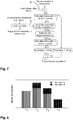
- Figure 12 illustrates another possible use case of a control method according to the invention.
- the first modulator 1a is formed by a tunable lens 2, which can only modulate defocus (Z 2,0 in Zernike notation - cf. Figure 13 ) .
- the 2 nd modulator 1b which is formed by a deformable phase plate (DPP) 13 can not only tune defocus but also higher order modes. Hence, the DPP 13 can actively compensate for higher order aberrations introduced by the tunable lens. At the same time, the DPP 13 can provide fine tuning of the overall defocus provided by the cascade of both modulators 1a, 1b.
- DPP deformable phase plate
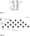
- Figure 13 depicts several lower order (radial order n ⁇ 2) and higher order (radial order n ⁇ 3) fundamental modes in the form of Zernike polynomials Z n,m .
- at least one of the multitude of modulators operated with a method according to the invention may be designed mainly for lower-order correction, while at least one other of these modulators may be optimized for higher order aberration.
- the modulation with respect to this particular mode can be split up among different modulators, and their superimposed responses can boost the modulation of this particular mode.
- FIG 14 and 15 finally illustrate two possible examples of imaging systems 11 in the form of light microscopes according to the invention, each one featuring a high NA microscope objective 10 for high resolution imaging of a sample 12, sandwiched between transparent microscope slides. Again, the accompanying control systems are not shown, in particular the required modulator drivers are not visible.
- Each system 11 comprises at least two serially cascaded wavefront modulators 1a, 1b jointly generating a modulated output wavefront Z o that is propagating along the respective detection path.
- the target wavefront required for the control of the modulators is obtained in both systems 11 through a sensorless wavefront estimation algorithm, as the microscopes do not feature a wavefront sensor 8.
- the imaging system 11 implements a multi-conjugate-adaptive-optics (MCAO) system: modulator 1a is placed at a first plane L1' that is conjugated to a layer L1 within the sample 12.
- the second modulator 1b is placed at a second plane L2' conjugated to another layer L2 within the sample 12.
- each of the modulators can compensate optical aberrations which are produced in the respective aberrating layer L1, L2, i.e. the locations of modulators 1a, 1b are conjugated, respectively, to the aberrating layers L1 and L2, which the modulators 1a, 1b are meant to correct separately.
- modulators 1a, 1b of the cascade may be used to separately correct aberrating layers L1, L2 located at different depths along the optical axis of the system 11.
- the imaging system 11 implements a pupil-plane-adaptive-optics (PPAO) system: the second modulator 1b is placed at a plane P' that is conjugated to the pupil P of the objective 10 defining the numerical aperture (NA) of the objective 10.
- the first modulator 1a is placed in close vicinity to plane P'.
- the distance between the two modulators 1a, 1b is less than two times of a diameter of an optical aperture of the first modulator 1a.
- the transfer of the pupil P onto the modulator 1b is accomplished using the relay optics 7, which is formed as a telescope comprising two doublets 16a, 16b.
- the modulators 1a, 1b are placed between the two lenses 16a, 16b, forming the relay optic 7, i.e. within diverging beams of the detection path of the microscope, allowing them to correct aberrations produced in layers L1 and L2 separately.
- the modulators 1a, 1b are placed in a portion of the detection path in which the light is collimated by the relay optic 7.
- the modulators 1a, 1b correct for the cumulative aberrations on the entire field of view (FoV).
- the modulators 1a, 1b can be operated with a simultaneous control method as explained herein.
- control methods proposed herein are simultaneous methods and can be done in real-time making them suitable for correction of dynamically fast changing aberrations.
- the methods can be open-loop, do not require a wavefront sensor and can thus be used together with sensorless aberration estimation algorithms.
- Using the proposed method it is possible to have a common space of M shared modes which are jointly modulated by at least two of the multitude of modulators. This approach results in extending the amplitude range and fidelity of the aberration correction.
- Employing an optimization-based control strategy for calculating the control signals of each modulator is advantageous for fast and accurate best-mode control of each modulator.
- the optimization algorithm used can be convex, and can consider physical and practical boundary constraints.
- the obtained solution for an individual control signal ci may guarantee optimal performance of each modulator.
- the behavior of each modulator can be estimated using their respective response model and by employing the optimal control signals calculated using a convex optimization algorithm.
- the method proposed here is not limited to only two modulators but can be extended for driving a higher number of modulators.
- the method is particularly suited for driving multiple deformable phase plates (DPPs) arranged in a cascaded configuration.
- a novel simple and efficient method for control of a multitude of wavefront modulators 1a, 1b sharing a common optical axis 19.
- the method enables real-time correction of dynamic, fast changing aberrations by providing independent control signals ci for controlling the individual modulators 1a, 1b simultaneously.
- independent control signals ci By sharing modes among the modulators 1a, 1b, it is possible to increase the available amplitude and fidelity of the wavefront modulation.
- independent calculation of the control signals ci ensures individual best-performance of each modulator 1 and high total modulation fidelity (c.f. Figure 9 ).
Landscapes
- Physics & Mathematics (AREA)
- General Physics & Mathematics (AREA)
- Optics & Photonics (AREA)
- Engineering & Computer Science (AREA)
- Multimedia (AREA)
- Chemical & Material Sciences (AREA)
- Analytical Chemistry (AREA)
- Optical Modulation, Optical Deflection, Nonlinear Optics, Optical Demodulation, Optical Logic Elements (AREA)
Priority Applications (1)
| Application Number | Priority Date | Filing Date | Title |
|---|---|---|---|
| EP20182549.4A EP3929648B1 (fr) | 2020-06-26 | 2020-06-26 | Procédé de commande de modulateurs de phase en cascade |
Applications Claiming Priority (1)
| Application Number | Priority Date | Filing Date | Title |
|---|---|---|---|
| EP20182549.4A EP3929648B1 (fr) | 2020-06-26 | 2020-06-26 | Procédé de commande de modulateurs de phase en cascade |
Publications (3)
| Publication Number | Publication Date |
|---|---|
| EP3929648A1 true EP3929648A1 (fr) | 2021-12-29 |
| EP3929648C0 EP3929648C0 (fr) | 2024-05-22 |
| EP3929648B1 EP3929648B1 (fr) | 2024-05-22 |
Family
ID=71266286
Family Applications (1)
| Application Number | Title | Priority Date | Filing Date |
|---|---|---|---|
| EP20182549.4A Active EP3929648B1 (fr) | 2020-06-26 | 2020-06-26 | Procédé de commande de modulateurs de phase en cascade |
Country Status (1)
| Country | Link |
|---|---|
| EP (1) | EP3929648B1 (fr) |
Cited By (1)
| Publication number | Priority date | Publication date | Assignee | Title |
|---|---|---|---|---|
| US20240094607A1 (en) * | 2022-09-20 | 2024-03-21 | Apple Inc. | Miniaturized adaptive optics with deformable phase plate for digital tilt and aberration correction |
Citations (2)
| Publication number | Priority date | Publication date | Assignee | Title |
|---|---|---|---|---|
| US20170302498A1 (en) * | 2014-09-25 | 2017-10-19 | Citizen Watch Co., Ltd. | Phase modulation device and laser microscope |
| DE102018110083A1 (de) * | 2018-04-26 | 2019-10-31 | Carl Zeiss Microscopy Gmbh | Optikanordnung zur flexiblen Mehrfarbbeleuchtung für ein Lichtmikroskop und Verfahren hierzu |
-
2020
- 2020-06-26 EP EP20182549.4A patent/EP3929648B1/fr active Active
Patent Citations (2)
| Publication number | Priority date | Publication date | Assignee | Title |
|---|---|---|---|---|
| US20170302498A1 (en) * | 2014-09-25 | 2017-10-19 | Citizen Watch Co., Ltd. | Phase modulation device and laser microscope |
| DE102018110083A1 (de) * | 2018-04-26 | 2019-10-31 | Carl Zeiss Microscopy Gmbh | Optikanordnung zur flexiblen Mehrfarbbeleuchtung für ein Lichtmikroskop und Verfahren hierzu |
Cited By (2)
| Publication number | Priority date | Publication date | Assignee | Title |
|---|---|---|---|---|
| US20240094607A1 (en) * | 2022-09-20 | 2024-03-21 | Apple Inc. | Miniaturized adaptive optics with deformable phase plate for digital tilt and aberration correction |
| US12498621B2 (en) * | 2022-09-20 | 2025-12-16 | Apple Inc. | Miniaturized adaptive optics with deformable phase plate for digital tilt and aberration correction |
Also Published As
| Publication number | Publication date |
|---|---|
| EP3929648C0 (fr) | 2024-05-22 |
| EP3929648B1 (fr) | 2024-05-22 |
Similar Documents
| Publication | Publication Date | Title |
|---|---|---|
| US11841288B2 (en) | Optical measurement method and system and optical device manufacturing system | |
| US20200073118A1 (en) | Correcting undesired distortions or aberrations and generating desired wavefronts in optical imaging, sensing, signaling and other applications based on bi-valued walsh functions | |
| US6771417B1 (en) | Applications of adaptive optics in microscopy | |
| CA2303474C (fr) | Appareil optique et methode d'ajustement dudit appareil | |
| US8624177B2 (en) | Refined optical system | |
| Landman et al. | Nonlinear wavefront reconstruction with convolutional neural networks for Fourier-based wavefront sensors | |
| US6977777B1 (en) | Active optical zoom system | |
| CA2267431A1 (fr) | Microscope avec optique adaptif | |
| JP4576137B2 (ja) | 顕微鏡 | |
| US20230418087A1 (en) | High-resolution light-field projector | |
| CN104122609A (zh) | 基于液晶空间光调制器的可变焦透镜实际焦距计算方法 | |
| US20090034042A1 (en) | Apparatus for Swiveling an Optical Beam | |
| Wu et al. | Adaptive optics for dynamic aberration compensation using parallel model-based controllers based on a field programmable gate array | |
| EP3929648B1 (fr) | Procédé de commande de modulateurs de phase en cascade | |
| Soummer et al. | High-contrast imager for complex aperture telescopes (HiCAT): 8. Dark zone demonstration with simultaneous closed-loop low-order wavefront sensing and control | |
| WO2008076444A1 (fr) | Système optique perfectionné | |
| Kautz et al. | Phasing the Giant Magellan Telescope: lab experiments and first on-sky demonstration | |
| JP4189798B2 (ja) | 可変焦点レンズを用いた定倍率結像方法と装置 | |
| Gerard et al. | Laboratory demonstration of real-time focal plane wavefront control of residual atmospheric speckles | |
| JP2002040368A (ja) | 光駆動型波面補正映像方法及び装置 | |
| EP4043195A1 (fr) | Fabrication in situ de surfaces optiques de forme libre | |
| Von Bokern et al. | Modal control for an adaptive optics system using LQG compensation | |
| Madhusudhana et al. | Optical tweezer generation using automated alignment and adaptive optics | |
| CN121766468A (zh) | 一种光学寻址系统、方法及量子计算机 | |
| Mauch et al. | Adaptive Optics control for laser material processing |
Legal Events
| Date | Code | Title | Description |
|---|---|---|---|
| PUAI | Public reference made under article 153(3) epc to a published international application that has entered the european phase |
Free format text: ORIGINAL CODE: 0009012 |
|
| STAA | Information on the status of an ep patent application or granted ep patent |
Free format text: STATUS: THE APPLICATION HAS BEEN PUBLISHED |
|
| AK | Designated contracting states |
Kind code of ref document: A1 Designated state(s): AL AT BE BG CH CY CZ DE DK EE ES FI FR GB GR HR HU IE IS IT LI LT LU LV MC MK MT NL NO PL PT RO RS SE SI SK SM TR |
|
| B565 | Issuance of search results under rule 164(2) epc |
Effective date: 20201130 |
|
| STAA | Information on the status of an ep patent application or granted ep patent |
Free format text: STATUS: REQUEST FOR EXAMINATION WAS MADE |
|
| 17P | Request for examination filed |
Effective date: 20220125 |
|
| RBV | Designated contracting states (corrected) |
Designated state(s): AL AT BE BG CH CY CZ DE DK EE ES FI FR GB GR HR HU IE IS IT LI LT LU LV MC MK MT NL NO PL PT RO RS SE SI SK SM TR |
|
| GRAP | Despatch of communication of intention to grant a patent |
Free format text: ORIGINAL CODE: EPIDOSNIGR1 |
|
| STAA | Information on the status of an ep patent application or granted ep patent |
Free format text: STATUS: GRANT OF PATENT IS INTENDED |
|
| INTG | Intention to grant announced |
Effective date: 20231201 |
|
| GRAJ | Information related to disapproval of communication of intention to grant by the applicant or resumption of examination proceedings by the epo deleted |
Free format text: ORIGINAL CODE: EPIDOSDIGR1 |
|
| STAA | Information on the status of an ep patent application or granted ep patent |
Free format text: STATUS: REQUEST FOR EXAMINATION WAS MADE |
|
| GRAS | Grant fee paid |
Free format text: ORIGINAL CODE: EPIDOSNIGR3 |
|
| STAA | Information on the status of an ep patent application or granted ep patent |
Free format text: STATUS: GRANT OF PATENT IS INTENDED |
|
| GRAP | Despatch of communication of intention to grant a patent |
Free format text: ORIGINAL CODE: EPIDOSNIGR1 |
|
| INTC | Intention to grant announced (deleted) | ||
| GRAF | Information related to payment of grant fee modified |
Free format text: ORIGINAL CODE: EPIDOSCIGR3 |
|
| INTG | Intention to grant announced |
Effective date: 20240319 |
|
| GRAA | (expected) grant |
Free format text: ORIGINAL CODE: 0009210 |
|
| STAA | Information on the status of an ep patent application or granted ep patent |
Free format text: STATUS: THE PATENT HAS BEEN GRANTED |
|
| AK | Designated contracting states |
Kind code of ref document: B1 Designated state(s): AL AT BE BG CH CY CZ DE DK EE ES FI FR GB GR HR HU IE IS IT LI LT LU LV MC MK MT NL NO PL PT RO RS SE SI SK SM TR |
|
| REG | Reference to a national code |
Ref country code: GB Ref legal event code: FG4D |
|
| REG | Reference to a national code |
Ref country code: CH Ref legal event code: EP |
|
| REG | Reference to a national code |
Ref country code: DE Ref legal event code: R081 Ref document number: 602020031192 Country of ref document: DE Owner name: ALBERT-LUDWIGS-UNIVERSITAET FREIBURG, KOERPERS, DE Free format text: FORMER OWNER: ANMELDERANGABEN UNKLAR / UNVOLLSTAENDIG, 80297 MUENCHEN, DE |
|
| REG | Reference to a national code |
Ref country code: IE Ref legal event code: FG4D |
|
| REG | Reference to a national code |
Ref country code: DE Ref legal event code: R096 Ref document number: 602020031192 Country of ref document: DE |
|
| U01 | Request for unitary effect filed |
Effective date: 20240610 |
|
| U07 | Unitary effect registered |
Designated state(s): AT BE BG DE DK EE FI FR IT LT LU LV MT NL PT SE SI Effective date: 20240618 |
|
| U20 | Renewal fee for the european patent with unitary effect paid |
Year of fee payment: 5 Effective date: 20240627 |
|
| PG25 | Lapsed in a contracting state [announced via postgrant information from national office to epo] |
Ref country code: IS Free format text: LAPSE BECAUSE OF FAILURE TO SUBMIT A TRANSLATION OF THE DESCRIPTION OR TO PAY THE FEE WITHIN THE PRESCRIBED TIME-LIMIT Effective date: 20240922 |
|
| PG25 | Lapsed in a contracting state [announced via postgrant information from national office to epo] |
Ref country code: HR Free format text: LAPSE BECAUSE OF FAILURE TO SUBMIT A TRANSLATION OF THE DESCRIPTION OR TO PAY THE FEE WITHIN THE PRESCRIBED TIME-LIMIT Effective date: 20240522 |
|
| PG25 | Lapsed in a contracting state [announced via postgrant information from national office to epo] |
Ref country code: GR Free format text: LAPSE BECAUSE OF FAILURE TO SUBMIT A TRANSLATION OF THE DESCRIPTION OR TO PAY THE FEE WITHIN THE PRESCRIBED TIME-LIMIT Effective date: 20240823 |
|
| PG25 | Lapsed in a contracting state [announced via postgrant information from national office to epo] |
Ref country code: ES Free format text: LAPSE BECAUSE OF FAILURE TO SUBMIT A TRANSLATION OF THE DESCRIPTION OR TO PAY THE FEE WITHIN THE PRESCRIBED TIME-LIMIT Effective date: 20240522 |
|
| PG25 | Lapsed in a contracting state [announced via postgrant information from national office to epo] |
Ref country code: PL Free format text: LAPSE BECAUSE OF FAILURE TO SUBMIT A TRANSLATION OF THE DESCRIPTION OR TO PAY THE FEE WITHIN THE PRESCRIBED TIME-LIMIT Effective date: 20240522 |
|
| PG25 | Lapsed in a contracting state [announced via postgrant information from national office to epo] |
Ref country code: PL Free format text: LAPSE BECAUSE OF FAILURE TO SUBMIT A TRANSLATION OF THE DESCRIPTION OR TO PAY THE FEE WITHIN THE PRESCRIBED TIME-LIMIT Effective date: 20240522 Ref country code: NO Free format text: LAPSE BECAUSE OF FAILURE TO SUBMIT A TRANSLATION OF THE DESCRIPTION OR TO PAY THE FEE WITHIN THE PRESCRIBED TIME-LIMIT Effective date: 20240822 Ref country code: IS Free format text: LAPSE BECAUSE OF FAILURE TO SUBMIT A TRANSLATION OF THE DESCRIPTION OR TO PAY THE FEE WITHIN THE PRESCRIBED TIME-LIMIT Effective date: 20240922 Ref country code: HR Free format text: LAPSE BECAUSE OF FAILURE TO SUBMIT A TRANSLATION OF THE DESCRIPTION OR TO PAY THE FEE WITHIN THE PRESCRIBED TIME-LIMIT Effective date: 20240522 Ref country code: GR Free format text: LAPSE BECAUSE OF FAILURE TO SUBMIT A TRANSLATION OF THE DESCRIPTION OR TO PAY THE FEE WITHIN THE PRESCRIBED TIME-LIMIT Effective date: 20240823 Ref country code: ES Free format text: LAPSE BECAUSE OF FAILURE TO SUBMIT A TRANSLATION OF THE DESCRIPTION OR TO PAY THE FEE WITHIN THE PRESCRIBED TIME-LIMIT Effective date: 20240522 Ref country code: RS Free format text: LAPSE BECAUSE OF FAILURE TO SUBMIT A TRANSLATION OF THE DESCRIPTION OR TO PAY THE FEE WITHIN THE PRESCRIBED TIME-LIMIT Effective date: 20240822 |
|
| PG25 | Lapsed in a contracting state [announced via postgrant information from national office to epo] |
Ref country code: CZ Free format text: LAPSE BECAUSE OF FAILURE TO SUBMIT A TRANSLATION OF THE DESCRIPTION OR TO PAY THE FEE WITHIN THE PRESCRIBED TIME-LIMIT Effective date: 20240522 |
|
| PG25 | Lapsed in a contracting state [announced via postgrant information from national office to epo] |
Ref country code: SK Free format text: LAPSE BECAUSE OF FAILURE TO SUBMIT A TRANSLATION OF THE DESCRIPTION OR TO PAY THE FEE WITHIN THE PRESCRIBED TIME-LIMIT Effective date: 20240522 Ref country code: RO Free format text: LAPSE BECAUSE OF FAILURE TO SUBMIT A TRANSLATION OF THE DESCRIPTION OR TO PAY THE FEE WITHIN THE PRESCRIBED TIME-LIMIT Effective date: 20240522 |
|
| PG25 | Lapsed in a contracting state [announced via postgrant information from national office to epo] |
Ref country code: SM Free format text: LAPSE BECAUSE OF FAILURE TO SUBMIT A TRANSLATION OF THE DESCRIPTION OR TO PAY THE FEE WITHIN THE PRESCRIBED TIME-LIMIT Effective date: 20240522 |
|
| PG25 | Lapsed in a contracting state [announced via postgrant information from national office to epo] |
Ref country code: SM Free format text: LAPSE BECAUSE OF FAILURE TO SUBMIT A TRANSLATION OF THE DESCRIPTION OR TO PAY THE FEE WITHIN THE PRESCRIBED TIME-LIMIT Effective date: 20240522 Ref country code: SK Free format text: LAPSE BECAUSE OF FAILURE TO SUBMIT A TRANSLATION OF THE DESCRIPTION OR TO PAY THE FEE WITHIN THE PRESCRIBED TIME-LIMIT Effective date: 20240522 Ref country code: RO Free format text: LAPSE BECAUSE OF FAILURE TO SUBMIT A TRANSLATION OF THE DESCRIPTION OR TO PAY THE FEE WITHIN THE PRESCRIBED TIME-LIMIT Effective date: 20240522 Ref country code: CZ Free format text: LAPSE BECAUSE OF FAILURE TO SUBMIT A TRANSLATION OF THE DESCRIPTION OR TO PAY THE FEE WITHIN THE PRESCRIBED TIME-LIMIT Effective date: 20240522 |
|
| REG | Reference to a national code |
Ref country code: CH Ref legal event code: PL |
|
| PG25 | Lapsed in a contracting state [announced via postgrant information from national office to epo] |
Ref country code: MC Free format text: LAPSE BECAUSE OF FAILURE TO SUBMIT A TRANSLATION OF THE DESCRIPTION OR TO PAY THE FEE WITHIN THE PRESCRIBED TIME-LIMIT Effective date: 20240522 |
|
| REG | Reference to a national code |
Ref country code: DE Ref legal event code: R097 Ref document number: 602020031192 Country of ref document: DE |
|
| PLBE | No opposition filed within time limit |
Free format text: ORIGINAL CODE: 0009261 |
|
| STAA | Information on the status of an ep patent application or granted ep patent |
Free format text: STATUS: NO OPPOSITION FILED WITHIN TIME LIMIT |
|
| PG25 | Lapsed in a contracting state [announced via postgrant information from national office to epo] |
Ref country code: IE Free format text: LAPSE BECAUSE OF NON-PAYMENT OF DUE FEES Effective date: 20240626 |
|
| GBPC | Gb: european patent ceased through non-payment of renewal fee |
Effective date: 20240822 |
|
| PG25 | Lapsed in a contracting state [announced via postgrant information from national office to epo] |
Ref country code: CH Free format text: LAPSE BECAUSE OF NON-PAYMENT OF DUE FEES Effective date: 20240630 |
|
| 26N | No opposition filed |
Effective date: 20250225 |
|
| PG25 | Lapsed in a contracting state [announced via postgrant information from national office to epo] |
Ref country code: GB Free format text: LAPSE BECAUSE OF NON-PAYMENT OF DUE FEES Effective date: 20240822 |
|
| U20 | Renewal fee for the european patent with unitary effect paid |
Year of fee payment: 6 Effective date: 20250623 |
|
| PG25 | Lapsed in a contracting state [announced via postgrant information from national office to epo] |
Ref country code: CY Free format text: LAPSE BECAUSE OF FAILURE TO SUBMIT A TRANSLATION OF THE DESCRIPTION OR TO PAY THE FEE WITHIN THE PRESCRIBED TIME-LIMIT; INVALID AB INITIO Effective date: 20200626 |
|
| PG25 | Lapsed in a contracting state [announced via postgrant information from national office to epo] |
Ref country code: HU Free format text: LAPSE BECAUSE OF FAILURE TO SUBMIT A TRANSLATION OF THE DESCRIPTION OR TO PAY THE FEE WITHIN THE PRESCRIBED TIME-LIMIT; INVALID AB INITIO Effective date: 20200626 |