EP3929883B1 - Appareil, procédé et programme - Google Patents
Appareil, procédé et programme Download PDFInfo
- Publication number
- EP3929883B1 EP3929883B1 EP21180748.2A EP21180748A EP3929883B1 EP 3929883 B1 EP3929883 B1 EP 3929883B1 EP 21180748 A EP21180748 A EP 21180748A EP 3929883 B1 EP3929883 B1 EP 3929883B1
- Authority
- EP
- European Patent Office
- Prior art keywords
- day
- electric lock
- unit
- reference time
- image data
- Prior art date
- Legal status (The legal status is an assumption and is not a legal conclusion. Google has not performed a legal analysis and makes no representation as to the accuracy of the status listed.)
- Active
Links
Images


Classifications
-
- G—PHYSICS
- G07—CHECKING-DEVICES
- G07C—TIME OR ATTENDANCE REGISTERS; REGISTERING OR INDICATING THE WORKING OF MACHINES; GENERATING RANDOM NUMBERS; VOTING OR LOTTERY APPARATUS; ARRANGEMENTS, SYSTEMS OR APPARATUS FOR CHECKING NOT PROVIDED FOR ELSEWHERE
- G07C9/00—Individual registration on entry or exit
- G07C9/00174—Electronically operated locks; Circuits therefor; Nonmechanical keys therefor, e.g. passive or active electrical keys or other data carriers without mechanical keys
- G07C9/00571—Electronically operated locks; Circuits therefor; Nonmechanical keys therefor, e.g. passive or active electrical keys or other data carriers without mechanical keys operated by interacting with a central unit
-
- G—PHYSICS
- G07—CHECKING-DEVICES
- G07C—TIME OR ATTENDANCE REGISTERS; REGISTERING OR INDICATING THE WORKING OF MACHINES; GENERATING RANDOM NUMBERS; VOTING OR LOTTERY APPARATUS; ARRANGEMENTS, SYSTEMS OR APPARATUS FOR CHECKING NOT PROVIDED FOR ELSEWHERE
- G07C9/00—Individual registration on entry or exit
-
- G—PHYSICS
- G07—CHECKING-DEVICES
- G07C—TIME OR ATTENDANCE REGISTERS; REGISTERING OR INDICATING THE WORKING OF MACHINES; GENERATING RANDOM NUMBERS; VOTING OR LOTTERY APPARATUS; ARRANGEMENTS, SYSTEMS OR APPARATUS FOR CHECKING NOT PROVIDED FOR ELSEWHERE
- G07C9/00—Individual registration on entry or exit
- G07C9/20—Individual registration on entry or exit involving the use of a pass
- G07C9/28—Individual registration on entry or exit involving the use of a pass the pass enabling tracking or indicating presence
-
- G—PHYSICS
- G07—CHECKING-DEVICES
- G07C—TIME OR ATTENDANCE REGISTERS; REGISTERING OR INDICATING THE WORKING OF MACHINES; GENERATING RANDOM NUMBERS; VOTING OR LOTTERY APPARATUS; ARRANGEMENTS, SYSTEMS OR APPARATUS FOR CHECKING NOT PROVIDED FOR ELSEWHERE
- G07C9/00—Individual registration on entry or exit
- G07C9/00174—Electronically operated locks; Circuits therefor; Nonmechanical keys therefor, e.g. passive or active electrical keys or other data carriers without mechanical keys
- G07C9/00309—Electronically operated locks; Circuits therefor; Nonmechanical keys therefor, e.g. passive or active electrical keys or other data carriers without mechanical keys operated with bidirectional data transmission between data carrier and locks
-
- G—PHYSICS
- G07—CHECKING-DEVICES
- G07C—TIME OR ATTENDANCE REGISTERS; REGISTERING OR INDICATING THE WORKING OF MACHINES; GENERATING RANDOM NUMBERS; VOTING OR LOTTERY APPARATUS; ARRANGEMENTS, SYSTEMS OR APPARATUS FOR CHECKING NOT PROVIDED FOR ELSEWHERE
- G07C9/00—Individual registration on entry or exit
- G07C9/00174—Electronically operated locks; Circuits therefor; Nonmechanical keys therefor, e.g. passive or active electrical keys or other data carriers without mechanical keys
- G07C9/00563—Electronically operated locks; Circuits therefor; Nonmechanical keys therefor, e.g. passive or active electrical keys or other data carriers without mechanical keys using personal physical data of the operator, e.g. finger prints, retinal images, voicepatterns
-
- G—PHYSICS
- G07—CHECKING-DEVICES
- G07C—TIME OR ATTENDANCE REGISTERS; REGISTERING OR INDICATING THE WORKING OF MACHINES; GENERATING RANDOM NUMBERS; VOTING OR LOTTERY APPARATUS; ARRANGEMENTS, SYSTEMS OR APPARATUS FOR CHECKING NOT PROVIDED FOR ELSEWHERE
- G07C9/00—Individual registration on entry or exit
- G07C9/20—Individual registration on entry or exit involving the use of a pass
- G07C9/29—Individual registration on entry or exit involving the use of a pass the pass containing active electronic elements, e.g. smartcards
-
- H—ELECTRICITY
- H04—ELECTRIC COMMUNICATION TECHNIQUE
- H04N—PICTORIAL COMMUNICATION, e.g. TELEVISION
- H04N7/00—Television systems
- H04N7/18—Closed-circuit television [CCTV] systems, i.e. systems in which the video signal is not broadcast
- H04N7/183—Closed-circuit television [CCTV] systems, i.e. systems in which the video signal is not broadcast for receiving images from a single remote source
- H04N7/186—Video door telephones
-
- G—PHYSICS
- G07—CHECKING-DEVICES
- G07C—TIME OR ATTENDANCE REGISTERS; REGISTERING OR INDICATING THE WORKING OF MACHINES; GENERATING RANDOM NUMBERS; VOTING OR LOTTERY APPARATUS; ARRANGEMENTS, SYSTEMS OR APPARATUS FOR CHECKING NOT PROVIDED FOR ELSEWHERE
- G07C2209/00—Indexing scheme relating to groups G07C9/00 - G07C9/38
- G07C2209/60—Indexing scheme relating to groups G07C9/00174 - G07C9/00944
- G07C2209/62—Comprising means for indicating the status of the lock
-
- G—PHYSICS
- G07—CHECKING-DEVICES
- G07C—TIME OR ATTENDANCE REGISTERS; REGISTERING OR INDICATING THE WORKING OF MACHINES; GENERATING RANDOM NUMBERS; VOTING OR LOTTERY APPARATUS; ARRANGEMENTS, SYSTEMS OR APPARATUS FOR CHECKING NOT PROVIDED FOR ELSEWHERE
- G07C9/00—Individual registration on entry or exit
- G07C9/00174—Electronically operated locks; Circuits therefor; Nonmechanical keys therefor, e.g. passive or active electrical keys or other data carriers without mechanical keys
-
- G—PHYSICS
- G08—SIGNALLING
- G08B—SIGNALLING SYSTEMS, e.g. PERSONAL CALLING SYSTEMS; ORDER TELEGRAPHS; ALARM SYSTEMS
- G08B13/00—Burglar, theft or intruder alarms
- G08B13/18—Actuation by interference with heat, light, or radiation of shorter wavelength; Actuation by intruding sources of heat, light, or radiation of shorter wavelength
- G08B13/189—Actuation by interference with heat, light, or radiation of shorter wavelength; Actuation by intruding sources of heat, light, or radiation of shorter wavelength using passive radiation detection systems
- G08B13/194—Actuation by interference with heat, light, or radiation of shorter wavelength; Actuation by intruding sources of heat, light, or radiation of shorter wavelength using passive radiation detection systems using image scanning and comparing systems
- G08B13/196—Actuation by interference with heat, light, or radiation of shorter wavelength; Actuation by intruding sources of heat, light, or radiation of shorter wavelength using passive radiation detection systems using image scanning and comparing systems using television cameras
- G08B13/19695—Arrangements wherein non-video detectors start video recording or forwarding but do not generate an alarm themselves
Definitions
- Patent Document 1 Japanese Patent Application Publication No. 2015-162232
- US 2016/093180 Al relates to a garage monitor in which a security system notifies a user of a security event when a movable barrier operator light turns on.
- the security system includes a camera in communication with control circuitry and a communication module.
- the control circuitry is configured to control operation of the camera.
- the communication module communicates with a light status detector that determines the status of an operator light associated with a movable barrier operator. When the operator light turns on, the light status detector sends a signal to the communication module, effecting the control circuitry to operate the camera to capture security data.
- the communication module then transmits the captured security data over a network to be accessible by a mobile device.
- WO 2017/136160 Al discloses a system and method for controlling access to an access point.
- the security system comprises a positioning unit that determines locations of user devices relative to a threshold of the access point, a surveillance camera that monitors the threshold, and an access control system that controls the access point based on the locations of the user devices and orientations of individuals carrying the user devices relative to the access point.
- the electric lock may be capable of performing automatic locking after unlocking and reading a unique ID of each key that is used.
- the apparatus may include a third storage unit configured to store a unique reference time of day and a history of entry and exit by an owner of each key, in association with a unique ID of each key.
- the judging unit may be configured to refer to the reference time of day and the history of entry and exit applicable for each key, and judge whether the electric lock is locked by the reference time of day in response to unlocking using the key.
- the sending unit may send the image data captured by the first monitoring camera after the reference time of day or the location information of the image data to the destination.
- Fig. 1 shows a security system 1 according to a first embodiment.
- the security system 1 includes an electric lock 2, an apparatus 4, and a file server 5.
- the electric lock 2, the apparatus 4, and the file server 5 may be connected with each other via a communication network 10.
- the electric lock 2, the apparatus 4, and the file server 5 are connected via a single communication network 10.
- the electric lock 2, the apparatus 4, and the file server 5 may be connected with each other via separate communication networks.
- the indicator 22 is provided on the surface of the electric lock 2, and may indicate a state of the electric lock 2 by emitting light.
- the indicator 22 may have at least one light emitting lamp, and may emit light of a color corresponding to a state of the electric lock 2.
- the communication unit 23 is configured to communicate with the apparatus 4 via the communication network 10.
- the communication unit 23 may send, to the apparatus 4, information about which state the electric lock 2 is in.
- the communication unit 23 may continuously send a current state of the electric lock 2, or may send a state after change to the apparatus 4 in response to the state of the electric lock 2 being changed.
- the apparatus 4 is configured to support security of the facility by cooperating with the electric lock 2 provided on the outside of the apparatus 4.
- the apparatus 4 has a detection unit 41, a history storage unit 42, a setting unit 43, a control unit 45, a monitoring camera 46, an image storage unit 47, and a communication unit 40.
- the history storage unit 42 is one example of a first storage unit, and is configured to store a lock history of the electric lock 2.
- the lock history may indicate a time of day when locking was performed in the past.
- the history storage unit 42 may store a history of the detection result obtained by the detection unit 41 in association with the detection time of day.
- the history storage unit 42 stores the time of day when the electric lock 2 is turned to the locked state, i.e., the time of day when the electric lock 2 is locked.
- the setting unit 43 is configured to set a reference time of day based on the lock history stored in the history storage unit 42.
- the setting unit 43 may supply the control unit 45 with the set reference time of day.
- the reference time of day may be a time of day when the electric lock 2 should be locked.
- the setting unit 43 detects the latest locking time of day in each of a plurality of days (which is also referred to as the final locking time of day), and set the time of day having a representative value thereof (as one example, the mean value, mode value, or median value) as the reference time of day.
- the setting unit 43 sets the latest time of day or the earliest time of day among the final locking time of day in each of the plurality of days as the reference time of day.
- the setting unit 43 may reset the reference time of day every day, or may reset every fixed time period (as one example, every week or every month).
- the control unit 45 is one example of a judging unit, and is configured to judge whether the electric lock 2 is locked at the reference time of day.
- the control unit 45 may perform judgement based on the detection result obtained by the detection unit 41, and may control the communication unit 40 according to the judging result.
- the control unit 45 may be capable of acquiring the current time of day, and may perform the judgement according to the fact that the current time of day is the reference time of day.
- the control unit 45 may perform clocking by itself, and may acquire the current time of day by wired or wireless communication from the outside.
- the control unit 45 may further control each unit of the apparatus 4.
- the monitoring camera 46 is configured to continuously perform capturing of a video image. However, the monitoring camera 46 may perform capturing of still images every reference interval (for example, 5 seconds). When the monitoring camera 46 captures video image data, the monitoring camera 46 may perform capturing at 30f/s, as one example.
- the monitoring camera 46 may be a camera for visible light or may be a camera for infrared light or ultraviolet light (as one example, X-ray).
- the monitoring camera 46 may store captured image data in the image storage unit 47.
- the communication unit 40 is configured to communicate with the electric lock 2.
- the communication unit 40 may receive the state of the electric lock 2 from the communication unit 23 of the electric lock 2, and supply the detection unit 41 with the state of the electric lock 2.
- the reference time of day is set based on the lock history of the electric lock 2, setting of an early time of day, when normally the electric lock 2 is not locked, as the reference time of day can be prevented. Therefore, sending of an image at safe time of day, when no checking is needed, can be prevented.
- setting of a late time of day, when normally the electric lock 2 is locked already (far before), as the reference time of day can be prevented. Therefore, late sensing of an abnormality due to late sending of an image can be prevented.
- Fig. 2 shows an operation of the apparatus 4.
- the apparatus 4 is configured to support the security of the facility by performing processings of Steps S11 to S15. Note that, at the time of starting of the operation, the reference time of day may be set by the setting unit 43 in advance.
- the detection unit 41 detects a state of the electric lock 2.
- the detection unit 41 may detect the state of the electric lock 2 (in the present embodiment, as one example, any of the locked state and the unlocked state) by communication between the electric lock 2 and the communication unit 40.
- the detection unit 41 may detect the state of the electric lock 2 before the reference time of day, or may detect at the reference time of day.
- the electric lock 2 has no automatic locking function for performing automatic locking after unlocking, but the electric lock 2 may have an automatic locking function.
- the driving unit 21 of the electric lock 2 may perform locking after a fixed time period has lapsed. Instead of this, after having performed unlocking, the driving unit 21 may perform locking in response to closing of a door on the doorway at which the electric lock 2A is provided.
- the history storage unit 42 may further store a history of entry and exit via the doorway.
- the history of entry and exit may indicate the time of day when entry to the inside of the doorway and exit to the outside are performed.
- the unlocking time of day is used as an entry time of day and stored in the history storage unit 42A.
- the unlocking time of day is used as an exit time of day and stored in the history storage unit 42A. Note that, the method for distinguishing between entry and exit is not limited thereto.
- control unit 45 may count the number of persons remaining on the inside of the doorway, based on the entry and exit history in the history storage unit 42. When the last single person remaining on the inside of the doorway exits, the control unit 45 may judge the person as the last exiting person. The control unit 45 may judge, at the reference time of day, whether the electric lock 2 is automatically locked after the last exiting person exited by unlocking the electric lock 2.
- the control unit 45 may judge, at a preset reference time of day, whether the electric lock 2 is locked.
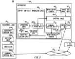
- Fig. 3 shows a security system 1A according to a second embodiment.
- the security system 1A includes an electric lock 2A and an apparatus 4A. Note that, in the system 1A according to the present embodiment, those ones substantially identical to the operation of the system 1 shown in Fig. 1 are labeled with the identical reference numerals, and their descriptions are abbreviated.
- the communication unit 23A may send, to the apparatus 4A, information about which state the electric lock 2A is in.
- the electric lock 2A is basically in the locked state because of the automatic locking function. Therefore, when the state of the electric lock 2A is changed to the transitional state or the unlocked state, the communication unit 23A may send, to the apparatus 4A, information indicating to that effect.
- the communication unit 23 may further send, to the apparatus 4A, an unique ID of the key read by the authentication unit 20A from the key that is used.
- the entry and exit managing unit 49 is configured to manage entry to the inside of the doorway and exit to the outside.
- the entry and exit managing unit 49 has a history storage unit 42A, a monitoring camera 46A, an identification unit 490, and an updating unit 491.
- the history storage unit 42A may store the history of entry and exit, in a similar manner to that of the history storage unit 42 in the variations of the first embodiment above described.
- the face authentication data is data for authenticating a user of the key, and may be data indicating a face of the legitimate owner of the key.
- the face authentication data may be image data of the face, or may be data indicating a characteristic of the face.
- the characteristic of the face may be a positional relationship between characteristic points of the face, or may be the color of eyes, skin, or hair, or may be the color, the shape, or the like of an accessory (as one example, glasses, pierced earrings, or the like).
- the face authentication data may be identical data as the data used for the authentication.
- face authentication data of the owner of the keys is further stored in association with the unique ID of each key, and a face in the image data capturing a person exiting to the outside from the doorway is collated with each face authentication data. Then, in response to the unique ID corresponding to the face in the image data being identified, the entry and exit history is updated by recording that the key of the unique ID is used for locking. Therefore, even in a case where the owner of another key exits to the outside from the doorway while one key is used to perform locking and unlocking, the entry and exit can be detected accurately.
- the entry and exit managing unit 49 may not have the identification unit 490 and the updating unit 491, and the control unit 45A may judge whether the key is used to lock the electric lock 2A by the reference time of day for each key.
- the indicator 22 of the electric lock 2 indicates a state of the electric lock 2 (as one example, the locked state, the unlocked state, or the transitional state), but the indicator 22 may indicate an authentication result obtained by the authentication unit 20.
- the detection unit 41 may detect that the light indicating the legitimate authentication result is emitted.
- the electric lock 2 and the apparatus 4 are communicatively connected with each other, the electric lock 2 may not have the indicator 22.
- Computer-readable instructions may be provided to a processor of a general purpose computer, special purpose computer, or other programmable data processing apparatus, or to a programmable circuitry, locally or via a local area network (LAN), wide area network (WAN) such as the Internet, or the like, to execute the computer-readable instructions to create means for performing operations specified in the flowcharts or block diagrams.
- processors include computer processors, processing units, microprocessors, digital signal processors, controllers, microcontrollers, and the like.
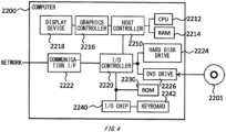
- the CPU 2212 may execute a communication program loaded onto the RAM 2214 to instruct communication processing to the communication interface 2222, based on the processing described in the communication program.
- the communication interface 2222 under control of the CPU 2212, reads transmission data stored on a transmission buffering region provided in a recording medium such as the RAM 2214, the hard disk drive 2224, the DVD-ROM 2201, or the IC card, and transmits the read transmission data to a network or writes reception data received from a network to a reception buffering region or the like provided on the recording medium.
- the above-explained program or software modules may be stored in the computer-readable medium on the computer 2200 or near the computer 2200.
- a recording medium such as a hard disk or a RAM provided in a server system connected to a dedicated communication network or the Internet can be used as the computer-readable medium, thereby providing the program to the computer 2200 via the network.
Landscapes
- Physics & Mathematics (AREA)
- General Physics & Mathematics (AREA)
- Engineering & Computer Science (AREA)
- Computer Networks & Wireless Communication (AREA)
- Multimedia (AREA)
- Signal Processing (AREA)
- Alarm Systems (AREA)
- Lock And Its Accessories (AREA)
- Selective Calling Equipment (AREA)
- Telephone Function (AREA)
- Telephonic Communication Services (AREA)
Claims (11)
- Appareil (4) comprenant :une unité de détection (41) configurée pour détecter un état d'une serrure électrique (2) disposée au niveau d'une porte ;une première caméra de surveillance (46) agencée à l'intérieur de la porte ; etune première unité de stockage (42) configurée pour stocker un historique de verrouillage de la serrure électrique (2), en stockant chaque heure du jour à laquelle la serrure électrique est verrouillée ;caractérisé en ce que l'appareil (4) comprend en outre :une unité de réglage (43) configurée pour régler une heure de référence du jour sur la base de l'historique de verrouillage en détectant l'heure de verrouillage finale du jour pour chacun d'une pluralité de jours et en réglant l'heure de référence du jour en tant que valeur représentative de celle-ci, de préférence en tant qu'une parmi une valeur moyenne, une valeur de mode ou une valeur médiane des heures de verrouillage finales de la pluralité de jours, ou en tant que dernière heure du jour ou première heure du jour parmi les heures de verrouillage finales du jour de la pluralité de jours ;une unité d'estimation (45) configurée pour estimer, à l'heure de référence du jour définie par l'unité de réglage, si la serrure électrique (2) est verrouillée ; etune unité d'envoi (40) configurée pour envoyer des données d'image capturées par la première caméra de surveillance (46) ou des informations de localisation des données d'image dans une unité de stockage d'image (47) de l'appareil ou un serveur de fichiers (5) à une destination correspondant à la serrure électrique (2), lorsque la serrure électrique (2) n'est pas verrouillée à l'heure de référence du jour.
- Appareil (4) selon la revendication 1,
dans lequel l'appareil comprend
une deuxième unité de stockage (42) configurée pour stocker un historique d'entrée et de sortie par la porte, dans lequel l'unité d'estimation (45) est configurée pour identifier une dernière personne sortante sur la base de l'historique d'entrée et de sortie stocké dans la deuxième unité de stockage (42), et
dans lequel l'unité d'estimation (45) est configurée pour estimer, à l'heure de référence du jour, si la serrure électrique (2) est verrouillée par verrouillage automatique en réponse à la sortie de la dernière personne sortante identifiée, la serrure électrique (2) présentant une fonction de verrouillage automatique pour effectuer un verrouillage automatique après le déverrouillage. - Appareil (4) selon la revendication 1,dans lequel l'appareil (4) est connecté, via un réseau de communication, à la serrure électrique (2) apte à effectuer un verrouillage automatique après déverrouillage et lecture d'un ID unique de chaque clé qui est utilisée,dans lequel l'appareil (4) comprend une troisième unité de stockage (42A) configurée pour stocker une heure de référence unique du jour et un historique d'entrée et de sortie par un propriétaire de chaque clé, en association avec un ID unique de chaque clé.
- Appareil (4) selon la revendication 3,
dans lequel la troisième unité de stockage (42A) est configurée pour stocker en outre des données d'authentification faciale d'un propriétaire de chaque clé, en association avec l'ID unique de la clé, dans lequel l'appareil (4) comprend en outre :une seconde caméra de surveillance (46A) configurée pour capturer le visage d'une personne sortante vers l'extérieur par la porte ;une unité d'identification (490) configurée pour comparer un visage dans des données d'image capturées par la seconde caméra de surveillance (46A) avec chaque donnée d'authentification faciale stockée dans l'unité de stockage, et identifier l'ID unique correspondant au visage dans les données d'image ; etune unité de mise à jour (491) configurée pour mettre à jour, en réponse à l'identification de l'ID unique par l'unité d'identification (490), l'historique d'entrée et de sortie en enregistrant que la clé de l'ID unique est utilisée pour sortir. - Appareil (4) selon l'une quelconque des revendications 1 à 4, comprenant une unité de communication (40) configurée pour communiquer avec la serrure électrique (2),
dans lequel l'unité de détection (41) est configurée pour détecter un état de la serrure électrique (2) par communication entre la serrure électrique (2) et l'unité de communication (40). - Appareil (4) selon la revendication 1, dans lequel l'unité de détection (41) est configurée pour détecter un état de la serrure électrique (2) par un changement d'un état d'émission de lumière d'un indicateur présent sur la serrure électrique (2).
- Appareil (4) selon l'une quelconque des revendications 1 à 6, dans lequel l'unité d'envoi (40) est configurée pour envoyer des données d'image capturées par la première caméra de surveillance (46) après l'heure de référence du jour ou les informations de localisation des données d'image à la destination.
- Appareil (4) selon l'une quelconque des revendications 1 à 7, dans lequel l'unité d'envoi (40) est en outre configurée pour envoyer des données d'image capturées par la première caméra de surveillance (46) à un serveur de fichiers qui est accessible par un autre dispositif.
- Procédé comprenant les étapes de :détection de l'état d'une serrure électrique disposée sur une porte ; etstockage d'un historique de verrouillage de la serrure électrique, en stockant chaque heure du jour à laquelle la serrure électrique est verrouillée dans une première unité de stockage (42) ;réglage, par une unité de réglage (43), d'une heure de référence du jour sur la base de l'historique de verrouillage en détectant l'heure de verrouillage finale du jour pour chacun d'une pluralité de jours et en réglant l'heure de référence du jour en tant que valeur représentative de celle-ci, de préférence en tant qu'une parmi une valeur moyenne, une valeur de mode ou une valeur médiane des heures de verrouillage finales de la pluralité de jours, ou en tant que dernière heure du jour ou première heure du jour parmi les heures de verrouillage finales du jour de la pluralité de jours ;estimation, par une unité d'estimation (45), de l'heure de référence du jour définie par l'unité de réglage (45), pour établir si la serrure électrique est verrouillée ; etenvoi, par une unité d'envoi (40), des données d'image capturées par une première caméra de surveillance (46) agencée à l'intérieur de la porte, dans laquelle une région de capture de la première caméra de surveillance (46) est l'intérieur d'une région située à l'intérieur de la porte, ou envoi des informations de localisation des données d'image capturées dans une unité de stockage d'images (47) ou un serveur de fichiers (5), à une destination correspondant à la serrure électrique, lorsque la serrure électrique n'est pas verrouillée à l'heure de référence du jour.
- Programme informatique comprenant des instructions pour mettre en œuvre le procédé selon la revendication 9 lorsqu'elles sont exécutées par un appareil selon la revendication 1.
- Support d'enregistrement lisible par ordinateur stockant le programme selon la revendication 10.
Applications Claiming Priority (1)
| Application Number | Priority Date | Filing Date | Title |
|---|---|---|---|
| JP2020110034A JP7188417B2 (ja) | 2020-06-25 | 2020-06-25 | 装置、方法およびプログラム |
Publications (3)
| Publication Number | Publication Date |
|---|---|
| EP3929883A1 EP3929883A1 (fr) | 2021-12-29 |
| EP3929883B1 true EP3929883B1 (fr) | 2025-04-16 |
| EP3929883B8 EP3929883B8 (fr) | 2025-05-28 |
Family
ID=76890768
Family Applications (1)
| Application Number | Title | Priority Date | Filing Date |
|---|---|---|---|
| EP21180748.2A Active EP3929883B8 (fr) | 2020-06-25 | 2021-06-22 | Appareil, procédé et programme |
Country Status (4)
| Country | Link |
|---|---|
| US (1) | US11587383B2 (fr) |
| EP (1) | EP3929883B8 (fr) |
| JP (1) | JP7188417B2 (fr) |
| CN (1) | CN113936359B (fr) |
Family Cites Families (25)
| Publication number | Priority date | Publication date | Assignee | Title |
|---|---|---|---|---|
| CA2359269A1 (fr) * | 2001-10-17 | 2003-04-17 | Biodentity Systems Corporation | Systeme d'imagerie utilise pour l'enregistrement d'images faciales et l'identification automatique |
| JP2005226413A (ja) * | 2004-02-16 | 2005-08-25 | Mitsubishi Electric Corp | 入退室管理装置 |
| JP2008305344A (ja) * | 2007-06-11 | 2008-12-18 | Nec Corp | セキュリティシステム、セキュリティ方法及び施錠検知装置 |
| JP5089437B2 (ja) * | 2008-03-04 | 2012-12-05 | キヤノン株式会社 | 撮像システム、撮像装置、制御方法及びプログラム |
| JP2010205092A (ja) * | 2009-03-05 | 2010-09-16 | Hitachi Ltd | 入退室管理システム |
| JP2011018298A (ja) * | 2009-07-07 | 2011-01-27 | Shuji Hatano | 生活状態監視システム |
| US8670752B2 (en) * | 2010-09-24 | 2014-03-11 | At&T Intellectual Property I, L.P. | Providing integrated service-entity premium communication services |
| MX342365B (es) * | 2012-08-16 | 2016-09-27 | Schlage Lock Co Llc | Sistema de lector inalámbrico. |
| JP6012538B2 (ja) * | 2013-04-25 | 2016-10-25 | 株式会社 日立産業制御ソリューションズ | 入退室管理システム、入退室管理システムの制御方法および入退室管理システム用のコンピュータ装置 |
| US9342936B2 (en) * | 2013-07-26 | 2016-05-17 | SkyBell Technologies, Inc. | Smart lock systems and methods |
| JP6305110B2 (ja) * | 2014-02-28 | 2018-04-04 | キヤノン株式会社 | 撮像装置、及び撮像システム |
| CN104050743B (zh) * | 2014-06-30 | 2016-06-08 | 重庆米睿科技有限公司 | 一种门禁系统的设防监控系统及方法 |
| AU2015323977B2 (en) * | 2014-09-30 | 2020-07-30 | The Chamberlain Group, Inc. | Garage monitor |
| US10074224B2 (en) * | 2015-04-20 | 2018-09-11 | Gate Labs Inc. | Access management system |
| US10373412B2 (en) | 2016-02-03 | 2019-08-06 | Sensormatic Electronics, LLC | System and method for controlling access to an access point |
| JP6765070B2 (ja) | 2016-06-01 | 2020-10-07 | パナソニックIpマネジメント株式会社 | 電気錠システム及び電気錠装置 |
| CN106408696A (zh) * | 2016-08-29 | 2017-02-15 | 珠海迈科智能科技股份有限公司 | 一种门禁监控系统 |
| JP2019206794A (ja) * | 2016-08-31 | 2019-12-05 | 日本電産リード株式会社 | 錠制御ユニット、電気錠付扉、及び電源制御システム |
| US11252548B2 (en) * | 2016-11-11 | 2022-02-15 | Carnival Corporation | Wireless guest engagement system |
| US10999092B2 (en) * | 2018-01-26 | 2021-05-04 | Edst, Llc | Modular intelligent door and frame |
| JP6848896B2 (ja) * | 2018-01-31 | 2021-03-24 | 京セラドキュメントソリューションズ株式会社 | 居室者監視システム |
| US10721444B2 (en) * | 2018-03-12 | 2020-07-21 | Delta Lock Company, LLC | Lock system including automation notification and surveillance integration |
| KR102250078B1 (ko) * | 2018-08-10 | 2021-05-12 | 주식회사 더벨 | 도어락 개폐장치, 중앙통제 서버 및 이를 이용하는 생산시스템 |
| CN109300212A (zh) * | 2018-09-29 | 2019-02-01 | 镇江微芯光子科技有限公司 | 一种自动门锁系统 |
| CN111080860A (zh) * | 2019-12-31 | 2020-04-28 | 常州科新永安电子锁有限公司 | 智能锁及控制方法、可读存储介质、服务器端和系统 |
-
2020
- 2020-06-25 JP JP2020110034A patent/JP7188417B2/ja active Active
-
2021
- 2021-04-28 CN CN202110465630.6A patent/CN113936359B/zh active Active
- 2021-06-10 US US17/343,792 patent/US11587383B2/en active Active
- 2021-06-22 EP EP21180748.2A patent/EP3929883B8/fr active Active
Also Published As
| Publication number | Publication date |
|---|---|
| CN113936359B (zh) | 2023-12-22 |
| JP7188417B2 (ja) | 2022-12-13 |
| CN113936359A (zh) | 2022-01-14 |
| EP3929883B8 (fr) | 2025-05-28 |
| US11587383B2 (en) | 2023-02-21 |
| US20210407239A1 (en) | 2021-12-30 |
| EP3929883A1 (fr) | 2021-12-29 |
| JP2022007214A (ja) | 2022-01-13 |
Similar Documents
| Publication | Publication Date | Title |
|---|---|---|
| US7817046B2 (en) | Method and apparatus for cataloging and poling movement in an environment for purposes of tracking and/or containment of infectious diseases | |
| CN110930566A (zh) | 监狱往来车辆的安全复核方法、系统、装置及可存储介质 | |
| EP3929883B1 (fr) | Appareil, procédé et programme | |
| US10636264B2 (en) | Office building security system using fiber sensing | |
| CN115359593B (zh) | 门禁管理方法、系统、电子设备及存储介质 | |
| CN110914875B (zh) | 基于位置的行为监测 | |
| EP4203465B1 (fr) | Serveur, procédé et programme de distribution | |
| EP3968294B1 (fr) | Appareil, système, procédé et programme | |
| EP3699880A1 (fr) | Dispositif de commande d'affichage de personne, système de commande d'affichage de personne et procédé de commande d'affichage de personne | |
| EP3961588B1 (fr) | Système et procédé permettant d'accéder des données d'image stockées | |
| EP3109837A1 (fr) | Système et procédé d'analyse intelligente d'incident dans un système de commande utilisant des cartes de sols | |
| US11967191B2 (en) | Device, method and storage medium | |
| CN120374005A (zh) | 一种基于图形识别及物联网技术的仓储高值耗材智能柜 | |
| EP3930317B1 (fr) | Appareil, procédé et programme | |
| EP3998388A1 (fr) | Système et procédé d'authentification | |
| CN113379245A (zh) | 一种城市社区人员管理方法及装置 |
Legal Events
| Date | Code | Title | Description |
|---|---|---|---|
| PUAI | Public reference made under article 153(3) epc to a published international application that has entered the european phase |
Free format text: ORIGINAL CODE: 0009012 |
|
| STAA | Information on the status of an ep patent application or granted ep patent |
Free format text: STATUS: THE APPLICATION HAS BEEN PUBLISHED |
|
| AK | Designated contracting states |
Kind code of ref document: A1 Designated state(s): AL AT BE BG CH CY CZ DE DK EE ES FI FR GB GR HR HU IE IS IT LI LT LU LV MC MK MT NL NO PL PT RO RS SE SI SK SM TR |
|
| B565 | Issuance of search results under rule 164(2) epc |
Effective date: 20211118 |
|
| STAA | Information on the status of an ep patent application or granted ep patent |
Free format text: STATUS: REQUEST FOR EXAMINATION WAS MADE |
|
| 17P | Request for examination filed |
Effective date: 20220607 |
|
| RBV | Designated contracting states (corrected) |
Designated state(s): AL AT BE BG CH CY CZ DE DK EE ES FI FR GB GR HR HU IE IS IT LI LT LU LV MC MK MT NL NO PL PT RO RS SE SI SK SM TR |
|
| P01 | Opt-out of the competence of the unified patent court (upc) registered |
Effective date: 20230603 |
|
| STAA | Information on the status of an ep patent application or granted ep patent |
Free format text: STATUS: EXAMINATION IS IN PROGRESS |
|
| 17Q | First examination report despatched |
Effective date: 20231108 |
|
| GRAP | Despatch of communication of intention to grant a patent |
Free format text: ORIGINAL CODE: EPIDOSNIGR1 |
|
| STAA | Information on the status of an ep patent application or granted ep patent |
Free format text: STATUS: GRANT OF PATENT IS INTENDED |
|
| INTG | Intention to grant announced |
Effective date: 20250116 |
|
| GRAS | Grant fee paid |
Free format text: ORIGINAL CODE: EPIDOSNIGR3 |
|
| GRAA | (expected) grant |
Free format text: ORIGINAL CODE: 0009210 |
|
| STAA | Information on the status of an ep patent application or granted ep patent |
Free format text: STATUS: THE PATENT HAS BEEN GRANTED |
|
| AK | Designated contracting states |
Kind code of ref document: B1 Designated state(s): AL AT BE BG CH CY CZ DE DK EE ES FI FR GB GR HR HU IE IS IT LI LT LU LV MC MK MT NL NO PL PT RO RS SE SI SK SM TR |
|
| REG | Reference to a national code |
Ref country code: GB Ref legal event code: FG4D |
|
| REG | Reference to a national code |
Ref country code: CH Ref legal event code: PK Free format text: BERICHTIGUNG B8 Ref country code: CH Ref legal event code: PK Free format text: BERICHTIGUNGEN Ref country code: CH Ref legal event code: EP |
|
| REG | Reference to a national code |
Ref country code: IE Ref legal event code: FG4D |
|
| REG | Reference to a national code |
Ref country code: DE Ref legal event code: R096 Ref document number: 602021029134 Country of ref document: DE |
|
| RAP4 | Party data changed (patent owner data changed or rights of a patent transferred) |
Owner name: YOKOGAWA ELECTRIC CORPORATION |
|
| RIN2 | Information on inventor provided after grant (corrected) |
Inventor name: WADA, ATSUSHI Inventor name: KOJIMA, OSAMU |
|
| PGFP | Annual fee paid to national office [announced via postgrant information from national office to epo] |
Ref country code: DE Payment date: 20250512 Year of fee payment: 5 |
|
| PGFP | Annual fee paid to national office [announced via postgrant information from national office to epo] |
Ref country code: AT Payment date: 20250721 Year of fee payment: 5 |
|
| REG | Reference to a national code |
Ref country code: NL Ref legal event code: MP Effective date: 20250416 |
|
| PG25 | Lapsed in a contracting state [announced via postgrant information from national office to epo] |
Ref country code: NL Free format text: LAPSE BECAUSE OF FAILURE TO SUBMIT A TRANSLATION OF THE DESCRIPTION OR TO PAY THE FEE WITHIN THE PRESCRIBED TIME-LIMIT Effective date: 20250416 |
|
| REG | Reference to a national code |
Ref country code: AT Ref legal event code: MK05 Ref document number: 1786318 Country of ref document: AT Kind code of ref document: T Effective date: 20250416 |
|
| PG25 | Lapsed in a contracting state [announced via postgrant information from national office to epo] |
Ref country code: ES Free format text: LAPSE BECAUSE OF FAILURE TO SUBMIT A TRANSLATION OF THE DESCRIPTION OR TO PAY THE FEE WITHIN THE PRESCRIBED TIME-LIMIT Effective date: 20250416 Ref country code: PT Free format text: LAPSE BECAUSE OF FAILURE TO SUBMIT A TRANSLATION OF THE DESCRIPTION OR TO PAY THE FEE WITHIN THE PRESCRIBED TIME-LIMIT Effective date: 20250818 Ref country code: FI Free format text: LAPSE BECAUSE OF FAILURE TO SUBMIT A TRANSLATION OF THE DESCRIPTION OR TO PAY THE FEE WITHIN THE PRESCRIBED TIME-LIMIT Effective date: 20250416 |
|
| REG | Reference to a national code |
Ref country code: LT Ref legal event code: MG9D |
|
| PG25 | Lapsed in a contracting state [announced via postgrant information from national office to epo] |
Ref country code: GR Free format text: LAPSE BECAUSE OF FAILURE TO SUBMIT A TRANSLATION OF THE DESCRIPTION OR TO PAY THE FEE WITHIN THE PRESCRIBED TIME-LIMIT Effective date: 20250717 Ref country code: NO Free format text: LAPSE BECAUSE OF FAILURE TO SUBMIT A TRANSLATION OF THE DESCRIPTION OR TO PAY THE FEE WITHIN THE PRESCRIBED TIME-LIMIT Effective date: 20250716 |
|
| PG25 | Lapsed in a contracting state [announced via postgrant information from national office to epo] |
Ref country code: PL Free format text: LAPSE BECAUSE OF FAILURE TO SUBMIT A TRANSLATION OF THE DESCRIPTION OR TO PAY THE FEE WITHIN THE PRESCRIBED TIME-LIMIT Effective date: 20250416 |
|
| PG25 | Lapsed in a contracting state [announced via postgrant information from national office to epo] |
Ref country code: BG Free format text: LAPSE BECAUSE OF FAILURE TO SUBMIT A TRANSLATION OF THE DESCRIPTION OR TO PAY THE FEE WITHIN THE PRESCRIBED TIME-LIMIT Effective date: 20250416 |
|
| PG25 | Lapsed in a contracting state [announced via postgrant information from national office to epo] |
Ref country code: HR Free format text: LAPSE BECAUSE OF FAILURE TO SUBMIT A TRANSLATION OF THE DESCRIPTION OR TO PAY THE FEE WITHIN THE PRESCRIBED TIME-LIMIT Effective date: 20250416 |
|
| PG25 | Lapsed in a contracting state [announced via postgrant information from national office to epo] |
Ref country code: AT Free format text: LAPSE BECAUSE OF FAILURE TO SUBMIT A TRANSLATION OF THE DESCRIPTION OR TO PAY THE FEE WITHIN THE PRESCRIBED TIME-LIMIT Effective date: 20250416 |
|
| PG25 | Lapsed in a contracting state [announced via postgrant information from national office to epo] |
Ref country code: RS Free format text: LAPSE BECAUSE OF FAILURE TO SUBMIT A TRANSLATION OF THE DESCRIPTION OR TO PAY THE FEE WITHIN THE PRESCRIBED TIME-LIMIT Effective date: 20250716 |
|
| PG25 | Lapsed in a contracting state [announced via postgrant information from national office to epo] |
Ref country code: IS Free format text: LAPSE BECAUSE OF FAILURE TO SUBMIT A TRANSLATION OF THE DESCRIPTION OR TO PAY THE FEE WITHIN THE PRESCRIBED TIME-LIMIT Effective date: 20250816 |
|
| PG25 | Lapsed in a contracting state [announced via postgrant information from national office to epo] |
Ref country code: LV Free format text: LAPSE BECAUSE OF FAILURE TO SUBMIT A TRANSLATION OF THE DESCRIPTION OR TO PAY THE FEE WITHIN THE PRESCRIBED TIME-LIMIT Effective date: 20250416 |
|
| PG25 | Lapsed in a contracting state [announced via postgrant information from national office to epo] |
Ref country code: SM Free format text: LAPSE BECAUSE OF FAILURE TO SUBMIT A TRANSLATION OF THE DESCRIPTION OR TO PAY THE FEE WITHIN THE PRESCRIBED TIME-LIMIT Effective date: 20250416 Ref country code: DK Free format text: LAPSE BECAUSE OF FAILURE TO SUBMIT A TRANSLATION OF THE DESCRIPTION OR TO PAY THE FEE WITHIN THE PRESCRIBED TIME-LIMIT Effective date: 20250416 |
|
| REG | Reference to a national code |
Ref country code: DE Ref legal event code: R097 Ref document number: 602021029134 Country of ref document: DE |
|
| PG25 | Lapsed in a contracting state [announced via postgrant information from national office to epo] |
Ref country code: CZ Free format text: LAPSE BECAUSE OF FAILURE TO SUBMIT A TRANSLATION OF THE DESCRIPTION OR TO PAY THE FEE WITHIN THE PRESCRIBED TIME-LIMIT Effective date: 20250416 |
|
| PG25 | Lapsed in a contracting state [announced via postgrant information from national office to epo] |
Ref country code: RO Free format text: LAPSE BECAUSE OF FAILURE TO SUBMIT A TRANSLATION OF THE DESCRIPTION OR TO PAY THE FEE WITHIN THE PRESCRIBED TIME-LIMIT Effective date: 20250416 Ref country code: SK Free format text: LAPSE BECAUSE OF FAILURE TO SUBMIT A TRANSLATION OF THE DESCRIPTION OR TO PAY THE FEE WITHIN THE PRESCRIBED TIME-LIMIT Effective date: 20250416 |
|
| REG | Reference to a national code |
Ref country code: CH Ref legal event code: H13 Free format text: ST27 STATUS EVENT CODE: U-0-0-H10-H13 (AS PROVIDED BY THE NATIONAL OFFICE) Effective date: 20260127 |
|
| PG25 | Lapsed in a contracting state [announced via postgrant information from national office to epo] |
Ref country code: IT Free format text: LAPSE BECAUSE OF FAILURE TO SUBMIT A TRANSLATION OF THE DESCRIPTION OR TO PAY THE FEE WITHIN THE PRESCRIBED TIME-LIMIT Effective date: 20250416 |
|
| PG25 | Lapsed in a contracting state [announced via postgrant information from national office to epo] |
Ref country code: MC Free format text: LAPSE BECAUSE OF FAILURE TO SUBMIT A TRANSLATION OF THE DESCRIPTION OR TO PAY THE FEE WITHIN THE PRESCRIBED TIME-LIMIT Effective date: 20250416 |
|
| PG25 | Lapsed in a contracting state [announced via postgrant information from national office to epo] |
Ref country code: LU Free format text: LAPSE BECAUSE OF NON-PAYMENT OF DUE FEES Effective date: 20250622 |
|
| PLBE | No opposition filed within time limit |
Free format text: ORIGINAL CODE: 0009261 |
|
| STAA | Information on the status of an ep patent application or granted ep patent |
Free format text: STATUS: NO OPPOSITION FILED WITHIN TIME LIMIT |
|
| REG | Reference to a national code |
Ref country code: CH Ref legal event code: L10 Free format text: ST27 STATUS EVENT CODE: U-0-0-L10-L00 (AS PROVIDED BY THE NATIONAL OFFICE) Effective date: 20260225 |
|
| REG | Reference to a national code |
Ref country code: BE Ref legal event code: MM Effective date: 20250630 |
|
| 26N | No opposition filed |
Effective date: 20260119 |
|
| GBPC | Gb: european patent ceased through non-payment of renewal fee |
Effective date: 20250716 |
|
| PG25 | Lapsed in a contracting state [announced via postgrant information from national office to epo] |
Ref country code: GB Free format text: LAPSE BECAUSE OF NON-PAYMENT OF DUE FEES Effective date: 20250716 |
|
| PG25 | Lapsed in a contracting state [announced via postgrant information from national office to epo] |
Ref country code: IE Free format text: LAPSE BECAUSE OF NON-PAYMENT OF DUE FEES Effective date: 20250622 |
|
| PG25 | Lapsed in a contracting state [announced via postgrant information from national office to epo] |
Ref country code: BE Free format text: LAPSE BECAUSE OF NON-PAYMENT OF DUE FEES Effective date: 20250630 |
|
| PG25 | Lapsed in a contracting state [announced via postgrant information from national office to epo] |
Ref country code: FR Free format text: LAPSE BECAUSE OF NON-PAYMENT OF DUE FEES Effective date: 20250630 |
|
| PG25 | Lapsed in a contracting state [announced via postgrant information from national office to epo] |
Ref country code: CH Free format text: LAPSE BECAUSE OF NON-PAYMENT OF DUE FEES Effective date: 20250630 |