EP3930157A1 - Procédé de correction d'une zone partielle d'une couche de matériau, couche de matériau, machine dynamoélectrique - Google Patents
Procédé de correction d'une zone partielle d'une couche de matériau, couche de matériau, machine dynamoélectrique Download PDFInfo
- Publication number
- EP3930157A1 EP3930157A1 EP20181397.9A EP20181397A EP3930157A1 EP 3930157 A1 EP3930157 A1 EP 3930157A1 EP 20181397 A EP20181397 A EP 20181397A EP 3930157 A1 EP3930157 A1 EP 3930157A1
- Authority
- EP
- European Patent Office
- Prior art keywords
- material layer
- light source
- tooth
- geometry
- deviation
- Prior art date
- Legal status (The legal status is an assumption and is not a legal conclusion. Google has not performed a legal analysis and makes no representation as to the accuracy of the status listed.)
- Withdrawn
Links
Images


Classifications
-
- H—ELECTRICITY
- H02—GENERATION; CONVERSION OR DISTRIBUTION OF ELECTRIC POWER
- H02K—DYNAMO-ELECTRIC MACHINES
- H02K15/00—Processes or apparatus specially adapted for manufacturing, assembling, maintaining or repairing of dynamo-electric machines
- H02K15/02—Processes or apparatus specially adapted for manufacturing, assembling, maintaining or repairing of dynamo-electric machines of stator or rotor bodies
-
- H—ELECTRICITY
- H02—GENERATION; CONVERSION OR DISTRIBUTION OF ELECTRIC POWER
- H02K—DYNAMO-ELECTRIC MACHINES
- H02K15/00—Processes or apparatus specially adapted for manufacturing, assembling, maintaining or repairing of dynamo-electric machines
- H02K15/12—Impregnating, moulding insulation, heating or drying of windings, stators, rotors or machines
-
- H—ELECTRICITY
- H02—GENERATION; CONVERSION OR DISTRIBUTION OF ELECTRIC POWER
- H02K—DYNAMO-ELECTRIC MACHINES
- H02K2213/00—Specific aspects, not otherwise provided for and not covered by codes H02K2201/00 - H02K2211/00
- H02K2213/03—Machines characterised by numerical values, ranges, mathematical expressions or similar information
Definitions
- the invention relates to a method for correcting a material position.
- EP 3595148 A1 describes a method for producing a material layer with a layer thickness between 0.5 and 500 ⁇ m with the following steps: applying a suspension, comprising at least one binding agent and solid particles, through a template to a base to obtain a green body, driving out the binding agent from the green body , in particular by means of debinding, creating permanent cohesion of the solid particles by heating and / or by means of compression, in particular by means of sintering.
- Material layers produced in this way usually have higher geometric tolerances than conventional sheets or magnetic sheets, in particular made by means of punching.
- a positional tolerance of the teeth or individual teeth leads to problems.
- a deviation of actual positions and / or actual geometries of the teeth from target positions and / or target geometries leads, among other things, to the fact that the teeth of the individual material layers are not congruent on top of each other and thus a clear width of a groove channel located between the teeth decreases in the material layer structure and less current-carrying material, in particular copper coils, can thus be introduced.
- the invention is based on the object of improving a material layer structure for a stator of a dynamoelectric machine.
- the optical unit can be an optical measuring unit.
- the optical unit is preferably a scanner.
- the optical unit can also be designed as a camera. Other designs of the optical unit are also conceivable.
- the material layer advantageously has the previous functions of a conventional sheet in a conventional sheet package and performs the tasks of a sheet.
- An outline of the material layer advantageously corresponds essentially to the outline of a sheet metal.
- the material layer is advantageously thinner than conventional sheet metal.
- the material layer structure advantageously has the previous functions of a laminated core and performs the tasks of a laminated core.
- the material layers are arranged one above the other to create the material layer structure.
- the material layers are preferably arranged in the direction of a matter of rotation, in other words: along an axis of rotation, of the material layer structure.
- the light source is a laser.
- the correction is preferably carried out by means of laser beam shaping. This has the advantage that selective correction is possible.
- a distortion which occurs during the melting of material and a subsequent re-solidification is preferably used in order to achieve a change in geometry.
- a tooth base is partially melted in such a way that the distortion that occurs during re-solidification is such that a tooth tip adapts to the target geometry, preferably taking into account a maximum tolerance of less than 5 ⁇ m, in particular less than 2 ⁇ m.
- the material layer is melted on a tooth root (in other words: in the area of the tooth root). This is used in particular to rotate the tooth head.
- the tooth base is an area where the tooth merges into the yoke.
- Material can also be melted on the tooth neck (in other words: tooth flank), i.e. between the tooth root and tooth tip.
- Other areas of the material layer can also be melted to change a geometry and / or position.
- the light source is an LED.
- An electron beam can also be used as a light source.
- Other light sources that enable melting or plastic deformation are also conceivable.
- a burl can also be used as a light source. It is also conceivable to use other sources that emit electromagnetic waves. Bundled electromagnetic waves can also be used.
- the material layer is partially heated by a further light source before the partial melting.
- a further light source is advantageously achieved with a laser and / or an LED.
- Other light sources are also conceivable.
- the ambient temperature is between 200 ° C. and 600 ° C., preferably between 300 ° C. and 500 ° C., and the material layer is heated in this way (e.g. in an oven).
- the further light source is preferably a preheating light source, the light source explained above is preferably a melting light source.
- the light source has a beam intensity between 80 kW / cm 2 and 120 kW / cm 2 , in particular between 90 kW / cm 2 and 110 kW / cm 2 .
- the stated values are advantageously based on a material of the material layer, in particular on a thermal conductivity of the material.
- the light source advantageously has a focus size between 0.005 mm and 10 mm, preferably between 50 ⁇ m and 150 ⁇ m.
- the focus size corresponds to a diameter of the light source at the moment of impact on the material layer.
- the focus size is advantageously smaller than the layer thickness of the material layer.
- the light source advantageously has a duration of action between 0.1 ms and 100 ms.
- the light source preferably pulsates during the exposure time.
- I. E. During the exposure period, the light source emits at least two light pulses.
- a light pulse has z.
- the further light source has a beam intensity between 1 kW / cm 2 and 10 kW / cm 2 .
- the further light source advantageously has a focus size between 1 mm and 5 cm, preferably between 1 cm and 5 cm.
- the further light source advantageously has a duration of action between 1 ms and 100 ms.
- the further light source preferably does not pulsate.
- preheating and melting are synchronous, i. H. the duration of action of the further light source (preheating light source) and the duration of action of the light source (melting light source) are at least essentially of the same length.
- the mentioned properties of the further light source during preheating offer the advantage that a penetration depth of a melt pool caused by the melting light source is increased.
- the object set above is also achieved by claim 13, ie a material layer corrected according to such a method, the material layer having a layer thickness between 0.5 and 500 ⁇ m, in particular between 10 and 100 ⁇ m.
- the corrected material layer preferably has an insulation material on at least one layer side.
- the method for correction is advantageously carried out before an insulation material is applied. However, it is also possible to carry out the correction procedure after the insulation material has been applied.
- the soft magnetic material is iron, nickel, cobalt and / or their alloys.
- other magnetically conductive, in particular ferromagnetic, materials are also conceivable.
- the insulation material is preferably lacquer, in particular baking lacquer.
- the insulation material, in particular the baking varnish, and the material layer are preferably materially connected.
- the insulation material is ceramic. Other insulation materials are also possible.
- the invention is suitable both for dynamo-electric rotary machines and for linear machines, in particular linear motors.
- the invention offers the advantage that dimensional accuracy is achieved through a single-tooth-specific reduction in the positional tolerances is increased significantly. This in turn offers the advantage that the construction of material layer structures can be simplified and even automated.
- material layers which in particular according to one in the patent EP 3 595 148 A1 described method were produced, can be assembled by the invention to form material layer structures that have only small tolerances, whereby a lower torque ripple can be achieved in dynamoelectric machines.
- material layer structures enable a high performance of the dynamo-electric machine.
- such machines are quiet and low in vibration.
- the invention also offers the advantage that the correction by means of a light source can be used universally and independently of the design.
- the method described is also inexpensive and quick and can also be used for large series.
- the invention is particularly suitable for machines, especially engines, which require high performance with low weight, especially for aircraft, helicopters and Formula E racing cars.
- the invention is also suitable for applications in which machines are moved on traverses and therefore particularly should be easy. These include exoskeletons, robots and generally hanging axes.
- the invention is suitable for all types of machines that have layers of material. These include in particular asynchronous machines, synchronous machines and reluctance machines.
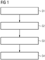
- FIG 1 shows a possible sequence of the method according to the invention for correcting a partial area of a material layer 1.
- the sub-area is preferably a tooth of a material layer.
- an actual geometry of the partial area is determined by means of an optical unit.
- the actual geometry is determined in FIG 2 described in more detail.
- step S2 the determined actual geometry is compared with a target geometry.
- a deviation of the actual geometry from the target geometry is determined.
- the material layer is partially melted by means of a light source.
- the light source is preferably designed as a laser, but it is also possible for the partial melting to take place by means of an LED.
- the partial melting is in FIG 3 described in more detail.
- FIG 2 shows a possible method for determining the actual geometry of the sub-area.
- the actual geometry is determined by means of an optical unit.
- a flatbed scanner or a line scanner or a camera can be used.
- Other scanners or devices that enable representation by means of an imaging method are also suitable.
- a scanner offers the advantage that the component to be measured can be mapped particularly well with a high resolution on a large area. For example, details in the range between 10 -2 and 10 -3 mm can be recorded and reproduced on an area between 10 4 and 10 5 mm 2.
- a material layer is measured with the optical unit, in particular with a scanner.
- a raw file of the material layer is generated. This is advantageously a raw image of the material layer in front of a preferably monochrome and / or matt background.
- the raw file in particular color-based, is released and binarized.
- the file is advantageously converted into a black and white image.
- the resulting image can then be aligned using a marking mark in method step E4.
- step E5 the actual geometry of at least one tooth, preferably of each tooth, is determined by determining the black / white transitions.
- a deviation from a target geometry is quantified and in a method step
- FIG 3 shows the partial melting
- the figure shows a section of a material layer 1 which is suitable for a stator 22 of a dynamoelectric machine 20.
- the material layer 1 has a layer thickness d between 0.5 and 500 ⁇ m, in particular between 10 and 100 ⁇ m.
- the material layer 1 has a soft magnetic material.
- the material layer 1 can have an insulation material 2 on at least one layer side.
- the figure shows a plurality of teeth 3.
- Each tooth 3 has a tooth tip 5, a tooth neck 4 and a tooth root 7.
- the figure also shows an end face 9 and a lateral surface 11.
- a directional laser beam 13 and a preheating laser beam 15 are also shown.
- the directional laser beam 13 in the figure is the light source or melting light source explained above.
- Another type of light source can also be used, e.g. B. an LED.
- the preheating laser beam 15 in the figure is the further light source or preheating light source explained above.
- Another type of light source can also be used, e.g. B. an LED.
- Partial misalignments in particular of the teeth, are selectively corrected by means of the directional laser beam 13.
- a distortion occurring during melting by means of the directional laser beam 13 and a subsequent re-solidification of the material is used to achieve a change in shape.
- a directional laser beam 13 with a focus size f13 with a preferably low radiation intensity is focused on the lateral surface 11 in the area of the tooth root 7 and the material is melted once or several times at certain points or over a large area.
- a small distortion in the area of the tooth root is sufficient to bring about a sufficiently large rotation of the tooth tip 5.
- the strength of the rotation can be controlled via various variables, for example via the laser intensity, focus size and / or exposure time.
- the focus size corresponds to a diameter of the respective light source at the moment of impact on the material layer.
- the focus size is advantageously smaller than the layer thickness of the material layer.
- the area of the tooth root 7 can be preheated using the preheating laser beam 15 with a focus size f15.
- the preheating laser beam 15 is preferably aimed at the end face 9, as shown in the figure. This enables the weld pool to penetrate even more deeply.
- the directional laser beam 13 and the optional preheating laser beam 15 enable the material layer to be straightened in a targeted manner. Misalignments from, for example, 100 ⁇ m to less than 20 ⁇ m can be corrected.
- FIG 4 shows tooth 3 before correction.
- FIG 5 shows tooth 3 after correction.
- the two figures show the tooth 3 having the tooth tip 5 and the tooth base 7.
- the two figures also show an actual geometry 16 and a target geometry 17.
- FIG 4 a zone of action of the directional laser 131 is also shown.
- a clear deviation of the actual geometry 16 from the target geometry 17 is shown before the directional laser beam 13 acts.
- FIG 5 it is clearly shown that the actual geometry 16 of the corrected tooth 3 only has a very small and sometimes negligible deviation from the target geometry 17.
- the before and after comparison from the FIGS. 4 and 5 shows how the action of the laser on the tooth root 7 enables a rotation of the tooth head 5.
- FIG 6 shows a dynamo-electric rotary machine 20, having a rotor 21, a stator 22 and a shaft 23.
- the stator 22 preferably has a plurality of material layers 1. These are arranged as a stator material layer structure 221.
- the rotor 21 has a plurality of material layers 24. These are arranged as a rotor material layer structure 211.
- the material layers 24 can undergo a similar correction using the method described.
- the invention can be used to correct material layers of grooved rotors or to change the shape of pockets for internal permanent magnets.
- the roundness of reluctance rotors can be improved in order to achieve a uniform air gap.
Landscapes
- Engineering & Computer Science (AREA)
- Manufacturing & Machinery (AREA)
- Power Engineering (AREA)
- Manufacture Of Motors, Generators (AREA)
Priority Applications (5)
| Application Number | Priority Date | Filing Date | Title |
|---|---|---|---|
| EP20181397.9A EP3930157A1 (fr) | 2020-06-22 | 2020-06-22 | Procédé de correction d'une zone partielle d'une couche de matériau, couche de matériau, machine dynamoélectrique |
| US18/012,138 US20230268812A1 (en) | 2020-06-22 | 2021-04-12 | Method for correcting a portion of a material layer, material layer, and dynamoelectric machine |
| PCT/EP2021/059373 WO2021259532A1 (fr) | 2020-06-22 | 2021-04-12 | Procédé de correction d'une partie d'une couche de matériau, couche de matériau et machine dynamo-électrique |
| EP21721853.6A EP4128493A1 (fr) | 2020-06-22 | 2021-04-12 | Procédé de correction d'une partie d'une couche de matériau, couche de matériau et machine dynamo-électrique |
| CN202180044253.7A CN115917942A (zh) | 2020-06-22 | 2021-04-12 | 校正材料层的部分区域的校正方法、材料层、电动机 |
Applications Claiming Priority (1)
| Application Number | Priority Date | Filing Date | Title |
|---|---|---|---|
| EP20181397.9A EP3930157A1 (fr) | 2020-06-22 | 2020-06-22 | Procédé de correction d'une zone partielle d'une couche de matériau, couche de matériau, machine dynamoélectrique |
Publications (1)
| Publication Number | Publication Date |
|---|---|
| EP3930157A1 true EP3930157A1 (fr) | 2021-12-29 |
Family
ID=71120092
Family Applications (2)
| Application Number | Title | Priority Date | Filing Date |
|---|---|---|---|
| EP20181397.9A Withdrawn EP3930157A1 (fr) | 2020-06-22 | 2020-06-22 | Procédé de correction d'une zone partielle d'une couche de matériau, couche de matériau, machine dynamoélectrique |
| EP21721853.6A Pending EP4128493A1 (fr) | 2020-06-22 | 2021-04-12 | Procédé de correction d'une partie d'une couche de matériau, couche de matériau et machine dynamo-électrique |
Family Applications After (1)
| Application Number | Title | Priority Date | Filing Date |
|---|---|---|---|
| EP21721853.6A Pending EP4128493A1 (fr) | 2020-06-22 | 2021-04-12 | Procédé de correction d'une partie d'une couche de matériau, couche de matériau et machine dynamo-électrique |
Country Status (4)
| Country | Link |
|---|---|
| US (1) | US20230268812A1 (fr) |
| EP (2) | EP3930157A1 (fr) |
| CN (1) | CN115917942A (fr) |
| WO (1) | WO2021259532A1 (fr) |
Citations (4)
| Publication number | Priority date | Publication date | Assignee | Title |
|---|---|---|---|---|
| US20080224549A1 (en) * | 2007-03-14 | 2008-09-18 | Mitsubishi Electric Corporation | Apparatus and Method for Correcting Shape of Inner Surface of Stator |
| US20190036429A1 (en) * | 2017-07-25 | 2019-01-31 | GM Global Technology Operations LLC | Electrically conductive copper components and joining processes therefor |
| EP3595148A1 (fr) | 2018-07-13 | 2020-01-15 | Siemens Aktiengesellschaft | Procédé de fabrication d'une couche de matériau et d'une structure de couche de matériau pour une machine rotative dynamoélectrique |
| US20200112210A1 (en) * | 2018-10-09 | 2020-04-09 | Ford Global Technologies, Llc | Electric Machine Component and Method to Fabricate |
Family Cites Families (7)
| Publication number | Priority date | Publication date | Assignee | Title |
|---|---|---|---|---|
| EP1340567A1 (fr) * | 2002-02-27 | 2003-09-03 | ALSTOM (Switzerland) Ltd | Procédé pour éliminer des défauts de coulée |
| CN104250807A (zh) * | 2013-06-28 | 2014-12-31 | 丹阳宏图激光科技有限公司 | 工具钢的激光修复方法 |
| US10199910B2 (en) * | 2014-10-03 | 2019-02-05 | Ford Global Technologies, Llc | Motor core formed from a single steel source and having separately processed rotor and stator laminations |
| JP2016110675A (ja) * | 2014-12-09 | 2016-06-20 | 日本電産株式会社 | スピンドルモータ、ディスク駆動装置、および、スピンドルモータのベースユニットの製造方法 |
| US10355537B2 (en) * | 2017-03-27 | 2019-07-16 | Ford Global Technologies, Llc | Method for adjusting magnetic permeability of electrical steel |
| JP6606311B1 (ja) * | 2018-11-16 | 2019-11-13 | 株式会社東芝 | 固定子の製造方法 |
| CN110266152B (zh) * | 2019-07-19 | 2022-07-26 | 绵阳西磁磁电有限公司 | 一种定子上涂附复合软磁材料的方法及其高速永磁电机 |
-
2020
- 2020-06-22 EP EP20181397.9A patent/EP3930157A1/fr not_active Withdrawn
-
2021
- 2021-04-12 US US18/012,138 patent/US20230268812A1/en active Pending
- 2021-04-12 CN CN202180044253.7A patent/CN115917942A/zh active Pending
- 2021-04-12 WO PCT/EP2021/059373 patent/WO2021259532A1/fr not_active Ceased
- 2021-04-12 EP EP21721853.6A patent/EP4128493A1/fr active Pending
Patent Citations (4)
| Publication number | Priority date | Publication date | Assignee | Title |
|---|---|---|---|---|
| US20080224549A1 (en) * | 2007-03-14 | 2008-09-18 | Mitsubishi Electric Corporation | Apparatus and Method for Correcting Shape of Inner Surface of Stator |
| US20190036429A1 (en) * | 2017-07-25 | 2019-01-31 | GM Global Technology Operations LLC | Electrically conductive copper components and joining processes therefor |
| EP3595148A1 (fr) | 2018-07-13 | 2020-01-15 | Siemens Aktiengesellschaft | Procédé de fabrication d'une couche de matériau et d'une structure de couche de matériau pour une machine rotative dynamoélectrique |
| US20200112210A1 (en) * | 2018-10-09 | 2020-04-09 | Ford Global Technologies, Llc | Electric Machine Component and Method to Fabricate |
Also Published As
| Publication number | Publication date |
|---|---|
| CN115917942A (zh) | 2023-04-04 |
| WO2021259532A1 (fr) | 2021-12-30 |
| US20230268812A1 (en) | 2023-08-24 |
| EP4128493A1 (fr) | 2023-02-08 |
Similar Documents
| Publication | Publication Date | Title |
|---|---|---|
| EP3595148B1 (fr) | Procédé de fabrication d'une couche de matériau et d'une structure de couche de matériau pour une machine rotative dynamoélectrique | |
| EP3788700B1 (fr) | Couche de matériau pour vitesses de rotation élevées et procédé de production | |
| EP2214862B1 (fr) | Élément structural arbre-moyeu et procédé de réalisation d'un tel élément structural | |
| EP3799261A1 (fr) | Stator à plusieurs pièces, machine électrique ainsi que procédé de fabrication d'un stator à plusieurs pièces et d'une machine électrique | |
| EP3266096B1 (fr) | Rotor pour un moteur électrique, arbre associé et procédé de production de celui | |
| EP3788701B1 (fr) | Couches de matériau robustes | |
| DE102008005079A1 (de) | Verfahren zur Herstellung von Motorkernteilen mit magnetischer Ausrichtung | |
| DE102016215701A1 (de) | Rotor einer elektrischen Maschine und Verfahren zur Montage des Rotors | |
| DE102018103478A1 (de) | Stator für einen elektromotor | |
| DE102020101148A1 (de) | Axialflussmaschine mit radial verlaufende Blechsegmente aufweisendem Stator | |
| DE102007015958B4 (de) | Kraft- und/oder reibschlüssige Verbindung | |
| EP1543601B1 (fr) | Stator et machine electrique | |
| DE102013220562A1 (de) | Baugruppe für eine elektrische Maschine, Verfahren zur Herstellung einer Baugruppe und elektrische Maschine mit einer Baugruppe | |
| AT519980A4 (de) | Statorkomponente für eine elektrische Maschine | |
| EP3930157A1 (fr) | Procédé de correction d'une zone partielle d'une couche de matériau, couche de matériau, machine dynamoélectrique | |
| DE102015213678A1 (de) | Sintergefügter Eisenkern einer Axialflussmaschine | |
| DE102022108196A1 (de) | Stator für bürstenlosen Motor oder Generator | |
| WO2015172916A1 (fr) | Rotor avec traitement thermique pour une machine électrique excitée par des aimants permanents | |
| DE102019122969A1 (de) | Aktivteil einer elektrischen Maschine, elektrische Maschine und Verfahren zur Herstellung einer vormontierten Baugruppe für den Aktivteil | |
| EP4068578A1 (fr) | Composant pour une machine dynamoélectrique | |
| DE102015214506A1 (de) | Rotor für eine Reluktanzmaschine, sowie ein Verfahren zum Herstellen eines solchen Rotors | |
| DE102012223323A1 (de) | Verfahren zur Herstellung eines Stators einer elektrischen Maschine, Stator und elektrische Maschine | |
| DE102024120493A1 (de) | Rotor für eine elektrische maschine | |
| WO2020025131A1 (fr) | Procédé servant à fabriquer une transmission magnétique, ainsi que transmission magnétique | |
| DE102024124399A1 (de) | Rotor für einen elektrischen Antrieb eines Kraftfahrzeugs, elektrischer Antrieb, Kraftfahrzeug und Verfahren |
Legal Events
| Date | Code | Title | Description |
|---|---|---|---|
| PUAI | Public reference made under article 153(3) epc to a published international application that has entered the european phase |
Free format text: ORIGINAL CODE: 0009012 |
|
| STAA | Information on the status of an ep patent application or granted ep patent |
Free format text: STATUS: THE APPLICATION HAS BEEN PUBLISHED |
|
| AK | Designated contracting states |
Kind code of ref document: A1 Designated state(s): AL AT BE BG CH CY CZ DE DK EE ES FI FR GB GR HR HU IE IS IT LI LT LU LV MC MK MT NL NO PL PT RO RS SE SI SK SM TR |
|
| B565 | Issuance of search results under rule 164(2) epc |
Effective date: 20201130 |
|
| STAA | Information on the status of an ep patent application or granted ep patent |
Free format text: STATUS: THE APPLICATION IS DEEMED TO BE WITHDRAWN |
|
| 18D | Application deemed to be withdrawn |
Effective date: 20220630 |