EP3930177A1 - Procédé de régulation d'une machine à courant triphasée électrique ainsi que système de machine à courant triphasée pour un tel procédé - Google Patents
Procédé de régulation d'une machine à courant triphasée électrique ainsi que système de machine à courant triphasée pour un tel procédé Download PDFInfo
- Publication number
- EP3930177A1 EP3930177A1 EP20181490.2A EP20181490A EP3930177A1 EP 3930177 A1 EP3930177 A1 EP 3930177A1 EP 20181490 A EP20181490 A EP 20181490A EP 3930177 A1 EP3930177 A1 EP 3930177A1
- Authority
- EP
- European Patent Office
- Prior art keywords
- phase machine
- signal component
- signal
- slot
- rotor
- Prior art date
- Legal status (The legal status is an assumption and is not a legal conclusion. Google has not performed a legal analysis and makes no representation as to the accuracy of the status listed.)
- Withdrawn
Links
- 238000000034 method Methods 0.000 title claims abstract description 42
- 230000005291 magnetic effect Effects 0.000 claims abstract description 21
- 230000000694 effects Effects 0.000 claims abstract description 19
- 230000005284 excitation Effects 0.000 claims description 44
- 230000008859 change Effects 0.000 claims description 13
- 238000012937 correction Methods 0.000 claims description 13
- 230000002123 temporal effect Effects 0.000 claims description 8
- 238000004364 calculation method Methods 0.000 claims description 5
- 230000001105 regulatory effect Effects 0.000 claims description 5
- 230000004044 response Effects 0.000 claims description 4
- 230000004907 flux Effects 0.000 description 8
- XEEYBQQBJWHFJM-UHFFFAOYSA-N Iron Chemical compound [Fe] XEEYBQQBJWHFJM-UHFFFAOYSA-N 0.000 description 6
- 238000006243 chemical reaction Methods 0.000 description 6
- 238000013461 design Methods 0.000 description 4
- 230000001360 synchronised effect Effects 0.000 description 4
- 238000012360 testing method Methods 0.000 description 4
- 230000033228 biological regulation Effects 0.000 description 3
- 238000010586 diagram Methods 0.000 description 3
- 229910052742 iron Inorganic materials 0.000 description 3
- 238000005259 measurement Methods 0.000 description 3
- 239000004065 semiconductor Substances 0.000 description 3
- 238000010276 construction Methods 0.000 description 2
- 230000001419 dependent effect Effects 0.000 description 2
- 230000008030 elimination Effects 0.000 description 2
- 238000003379 elimination reaction Methods 0.000 description 2
- 238000011156 evaluation Methods 0.000 description 2
- 238000001914 filtration Methods 0.000 description 2
- 230000006698 induction Effects 0.000 description 2
- 238000007620 mathematical function Methods 0.000 description 2
- 230000003213 activating effect Effects 0.000 description 1
- 230000009286 beneficial effect Effects 0.000 description 1
- 230000001427 coherent effect Effects 0.000 description 1
- 230000007547 defect Effects 0.000 description 1
- 230000002950 deficient Effects 0.000 description 1
- 230000035699 permeability Effects 0.000 description 1
- 238000012545 processing Methods 0.000 description 1
- 230000002441 reversible effect Effects 0.000 description 1
- 230000001052 transient effect Effects 0.000 description 1
- 238000004804 winding Methods 0.000 description 1
Images







Classifications
-
- H—ELECTRICITY
- H02—GENERATION; CONVERSION OR DISTRIBUTION OF ELECTRIC POWER
- H02P—CONTROL OR REGULATION OF ELECTRIC MOTORS, ELECTRIC GENERATORS OR DYNAMO-ELECTRIC CONVERTERS; CONTROLLING TRANSFORMERS, REACTORS OR CHOKE COILS
- H02P6/00—Arrangements for controlling synchronous motors or other dynamo-electric motors using electronic commutation dependent on the rotor position; Electronic commutators therefor
- H02P6/14—Electronic commutators
- H02P6/16—Circuit arrangements for detecting position
- H02P6/18—Circuit arrangements for detecting position without separate position detecting elements
- H02P6/183—Circuit arrangements for detecting position without separate position detecting elements using an injected high frequency signal
-
- H—ELECTRICITY
- H02—GENERATION; CONVERSION OR DISTRIBUTION OF ELECTRIC POWER
- H02P—CONTROL OR REGULATION OF ELECTRIC MOTORS, ELECTRIC GENERATORS OR DYNAMO-ELECTRIC CONVERTERS; CONTROLLING TRANSFORMERS, REACTORS OR CHOKE COILS
- H02P21/00—Arrangements or methods for the control of electric machines by vector control, e.g. by control of field orientation
- H02P21/06—Rotor flux based control involving the use of rotor position or rotor speed sensors
- H02P21/08—Indirect field-oriented control; Rotor flux feed-forward control
- H02P21/09—Field phase angle calculation based on rotor voltage equation by adding slip frequency and speed proportional frequency
-
- H—ELECTRICITY
- H02—GENERATION; CONVERSION OR DISTRIBUTION OF ELECTRIC POWER
- H02P—CONTROL OR REGULATION OF ELECTRIC MOTORS, ELECTRIC GENERATORS OR DYNAMO-ELECTRIC CONVERTERS; CONTROLLING TRANSFORMERS, REACTORS OR CHOKE COILS
- H02P21/00—Arrangements or methods for the control of electric machines by vector control, e.g. by control of field orientation
- H02P21/14—Estimation or adaptation of machine parameters, e.g. flux, current or voltage
-
- H—ELECTRICITY
- H02—GENERATION; CONVERSION OR DISTRIBUTION OF ELECTRIC POWER
- H02P—CONTROL OR REGULATION OF ELECTRIC MOTORS, ELECTRIC GENERATORS OR DYNAMO-ELECTRIC CONVERTERS; CONTROLLING TRANSFORMERS, REACTORS OR CHOKE COILS
- H02P21/00—Arrangements or methods for the control of electric machines by vector control, e.g. by control of field orientation
- H02P21/0003—Control strategies in general, e.g. linear type, e.g. P, PI, PID, using robust control
- H02P21/0025—Control strategies in general, e.g. linear type, e.g. P, PI, PID, using robust control implementing a off line learning phase to determine and store useful data for on-line control
-
- H—ELECTRICITY
- H02—GENERATION; CONVERSION OR DISTRIBUTION OF ELECTRIC POWER
- H02P—CONTROL OR REGULATION OF ELECTRIC MOTORS, ELECTRIC GENERATORS OR DYNAMO-ELECTRIC CONVERTERS; CONTROLLING TRANSFORMERS, REACTORS OR CHOKE COILS
- H02P21/00—Arrangements or methods for the control of electric machines by vector control, e.g. by control of field orientation
- H02P21/14—Estimation or adaptation of machine parameters, e.g. flux, current or voltage
- H02P21/18—Estimation of position or speed
-
- H—ELECTRICITY
- H02—GENERATION; CONVERSION OR DISTRIBUTION OF ELECTRIC POWER
- H02P—CONTROL OR REGULATION OF ELECTRIC MOTORS, ELECTRIC GENERATORS OR DYNAMO-ELECTRIC CONVERTERS; CONTROLLING TRANSFORMERS, REACTORS OR CHOKE COILS
- H02P21/00—Arrangements or methods for the control of electric machines by vector control, e.g. by control of field orientation
- H02P21/22—Current control, e.g. using a current control loop
-
- H—ELECTRICITY
- H02—GENERATION; CONVERSION OR DISTRIBUTION OF ELECTRIC POWER
- H02P—CONTROL OR REGULATION OF ELECTRIC MOTORS, ELECTRIC GENERATORS OR DYNAMO-ELECTRIC CONVERTERS; CONTROLLING TRANSFORMERS, REACTORS OR CHOKE COILS
- H02P21/00—Arrangements or methods for the control of electric machines by vector control, e.g. by control of field orientation
- H02P21/24—Vector control not involving the use of rotor position or rotor speed sensors
-
- H—ELECTRICITY
- H02—GENERATION; CONVERSION OR DISTRIBUTION OF ELECTRIC POWER
- H02P—CONTROL OR REGULATION OF ELECTRIC MOTORS, ELECTRIC GENERATORS OR DYNAMO-ELECTRIC CONVERTERS; CONTROLLING TRANSFORMERS, REACTORS OR CHOKE COILS
- H02P23/00—Arrangements or methods for the control of AC motors characterised by a control method other than vector control
- H02P23/0004—Control strategies in general, e.g. linear type, e.g. P, PI, PID, using robust control
- H02P23/0031—Control strategies in general, e.g. linear type, e.g. P, PI, PID, using robust control implementing a off line learning phase to determine and store useful data for on-line control
-
- H—ELECTRICITY
- H02—GENERATION; CONVERSION OR DISTRIBUTION OF ELECTRIC POWER
- H02P—CONTROL OR REGULATION OF ELECTRIC MOTORS, ELECTRIC GENERATORS OR DYNAMO-ELECTRIC CONVERTERS; CONTROLLING TRANSFORMERS, REACTORS OR CHOKE COILS
- H02P25/00—Arrangements or methods for the control of AC motors characterised by the kind of AC motor or by structural details
- H02P25/02—Arrangements or methods for the control of AC motors characterised by the kind of AC motor or by structural details characterised by the kind of motor
-
- H—ELECTRICITY
- H02—GENERATION; CONVERSION OR DISTRIBUTION OF ELECTRIC POWER
- H02P—CONTROL OR REGULATION OF ELECTRIC MOTORS, ELECTRIC GENERATORS OR DYNAMO-ELECTRIC CONVERTERS; CONTROLLING TRANSFORMERS, REACTORS OR CHOKE COILS
- H02P27/00—Arrangements or methods for the control of AC motors characterised by the kind of supply voltage
- H02P27/04—Arrangements or methods for the control of AC motors characterised by the kind of supply voltage using variable-frequency supply voltage, e.g. inverter or converter supply voltage
- H02P27/06—Arrangements or methods for the control of AC motors characterised by the kind of supply voltage using variable-frequency supply voltage, e.g. inverter or converter supply voltage using DC to AC converters or inverters
- H02P27/08—Arrangements or methods for the control of AC motors characterised by the kind of supply voltage using variable-frequency supply voltage, e.g. inverter or converter supply voltage using DC to AC converters or inverters with pulse width modulation
-
- H—ELECTRICITY
- H02—GENERATION; CONVERSION OR DISTRIBUTION OF ELECTRIC POWER
- H02P—CONTROL OR REGULATION OF ELECTRIC MOTORS, ELECTRIC GENERATORS OR DYNAMO-ELECTRIC CONVERTERS; CONTROLLING TRANSFORMERS, REACTORS OR CHOKE COILS
- H02P6/00—Arrangements for controlling synchronous motors or other dynamo-electric motors using electronic commutation dependent on the rotor position; Electronic commutators therefor
- H02P6/14—Electronic commutators
- H02P6/16—Circuit arrangements for detecting position
- H02P6/18—Circuit arrangements for detecting position without separate position detecting elements
- H02P6/186—Circuit arrangements for detecting position without separate position detecting elements using difference of inductance or reluctance between the phases
-
- H—ELECTRICITY
- H02—GENERATION; CONVERSION OR DISTRIBUTION OF ELECTRIC POWER
- H02P—CONTROL OR REGULATION OF ELECTRIC MOTORS, ELECTRIC GENERATORS OR DYNAMO-ELECTRIC CONVERTERS; CONTROLLING TRANSFORMERS, REACTORS OR CHOKE COILS
- H02P2207/00—Indexing scheme relating to controlling arrangements characterised by the type of motor
- H02P2207/01—Asynchronous machines
Definitions
- the invention relates to a method for regulating an electrical three-phase machine, in particular an asynchronous machine, with a rotor, a stator and at least two strands, with at least one electrical signal, in particular a voltage signal, being connected to at least one strand, preferably all strands, of the three-phase machine and an electrical signal curve, in particular a current curve, in which at least one strand is measured or determined.
- the invention also relates to a three-phase machine system for carrying out such a method.
- sensors such as incremental rotary encoders, absolute rotary encoders or resolvers can be used, which can be based on the most varied of physical principles.
- the disadvantage of all types of rotary encoders is the additional costs.
- rotary encoders only have a limited service life, which is often less than the planned service life of the three-phase machine. An alleged defect in a three-phase drive can often be traced back to the failure of such a sensor. Failures and downtimes, for example of defective trains on railway lines, can, however, involve considerable effort and high costs and should therefore be avoided if possible.
- Sensorless control methods make use of the fact that three-phase machines have asymmetries that are design-related or caused by electrical or magnetic effects during operation, which can change in time and place.
- the changes in the asymmetries usually cause changes in inductance and can therefore be detected, for example, via a changed increase in current.
- WO 99/39430 A1 a sensorless control method is described.
- An example of a design-related asymmetry is the rotor of a permanent magnet synchronous machine (PSM), which has permanent magnets at certain points that have a lower relative permeability than the surrounding areas with iron and therefore increase the magnetic resistance in the area of the permanent magnets compared to areas with iron.
- PSM permanent magnet synchronous machine
- the magnetic resistance is varied in time and location along the circumference of the air gap, which manifests itself in changes in inductance.
- An example of an electrical or magnetic asymmetry are local saturation phenomena of the magnetic flux paths in the three-phase machine.
- a usage signal component contained in the measured current curves is usually isolated from other signal components and evaluated, or the saturation signal is used.
- the slot signal component is caused by the slot of the rotor rotating past the slot of the stator and the associated change in inductance.
- the slotting signal component Since the changes in inductance caused by the slotting that is rotating past are relatively small, the slotting signal component is usually small and therefore, depending on the operating status and construction of the asynchronous machine, can only be identified and separated from other signal components with difficulty. In particular, when the load on the asynchronous machine increases, it is difficult or impossible to differentiate the slot signal component from other signal components.
- the object of the present invention to alleviate or even completely eliminate the disadvantages of the prior art.
- an intermodulation signal component caused by slot and magnetic saturation effects in the three-phase machine which is derived from the measured or in the at least one strand determined electrical signal course is determined, is used to control the three-phase machine.
- the intermodulation signal component can in particular be used to determine the rotor position, that is to say the angular position of the rotor, which can subsequently be used in the regulation of the three-phase machine.
- At least one electrical current curve is preferably measured or determined and used as the electrical signal curve. For this reason, the following explanations relate to measured current curves. However, measured or determined voltage profiles can also be used.
- the signal curve, in particular a current curve, in the at least one phase of the three-phase machine can be determined, for example, by measuring currents and / or voltages in an intermediate circuit of the converter, in an energy supply for the converter or in a feed to a machine-side converter.
- phase currents of the three-phase machine can be determined on the basis of an intermediate circuit current will. Since the method is particularly suitable for use in asynchronous machines or electrical machines with an at least partially asynchronous machine-like character (for example synchronous machines with a damper cage), the following statements relate primarily to asynchronous machines.
- the invention is based on the knowledge that, as will be explained in more detail below, there is a mathematical or physical relationship between the intermodulation signal component and the slot signal component representative of the angular position or speed of the rotor and therefore a control and position signal for regulation from the intermodulation signal component the three-phase machine can be derived and used.
- the slot signal component which is often difficult to determine, no longer has to be used directly.
- the intermodulation signal component in the signal response of the three-phase machine as a reaction to an excitation signal in most operating states of the three-phase machine is significantly larger than the keying signal component and can therefore be more easily identified and separated from other signal components.
- the intermodulation signal component can be evaluated in the time domain and / or in the frequency domain.
- an angular position and / or a rotational speed of the rotor can subsequently be determined from the intermodulation signal component.
- a saturation signal component can also be used and linked to the intermodulation signal component (see below).
- the intermodulation signal component is mainly caused by the effects of the slotting of the rotor or the stator of the three-phase machine and by effects of the magnetic saturation of magnetic flux paths within the three-phase machine. In most operating states, the intermodulation signal component has a different fundamental frequency than the user signal component and the saturation signal component. The effects described in turn cause their own signal components, which are also contained in the at least one measured current curve.
- the signal components in the current curve generated by the slotting of the rotor and the stator of the three-phase machine are referred to as slotting signal components.
- the fundamental frequency of the slot signal components generally corresponds essentially to N times the rotational frequency of the rotor, where N is the number of slots in the rotor is equivalent to.
- the signal components in the current curve caused by the temporal and spatial variation of the magnetic saturation of magnetic flux paths within the three-phase machine are referred to as saturation signal components.
- the fundamental frequency of the saturation signal component generally corresponds essentially to twice the fundamental or also the working wave of the machine.
- intermodulation signal component By physically linking the two effects mentioned, their signal components are also linked in the three-phase machine, thereby generating the intermodulation signal component, the frequencies of which are different from the frequencies of the saturation signal component and the frequencies of the user signal component in most operating states (intermodulation).
- the effect of the described intermodulation occurs in particular in asynchronous machines and electrical machines with at least a partial asynchronous machine-like character, which is why the method according to the invention is particularly suitable for regulating asynchronous machines.
- the intermodulation signal component in the reaction of the machine to an excitation signal was considered as an interference component and eliminated.
- the invention is based on the knowledge that there is a relationship between the intermodulation signal component and the slot signal component representative of the angular position and speed of the rotor, and that the intermodulation signal is therefore also suitable for regulating the three-phase machine.
- the sign of ⁇ sat in equation (1) depends on the design and type of the three-phase machine.
- the saturation signal component In order to calculate back to the usage signal component with the aid of the intermodulation signal component, the saturation signal component, preferably its fundamental frequency, can therefore also be used.
- the saturation signal component can be determined from the currents in the strands of the three-phase machine.
- the mentioned Signal components In addition to the basic frequencies, the mentioned Signal components also have harmonics, which, however, are neglected for the purpose of simplified explanation and due to their minor influence.
- the invention is further based on the knowledge that the relationship between the intermodulation signal component and the slot signal component can be used to determine an angular position and / or a speed of the rotor with the aid of the intermodulation signal component without determining or using the slot signal component directly from the current curve to have to.
- the intermodulation signal component can therefore advantageously be used in all control methods in which knowledge of the angular position of the rotor or the angular position of the flux linkage is necessary.
- the intermodulation signal is usually eliminated as an interference signal in the prior art and the usage signal component or the saturation signal component is used directly for regulation.
- the applied electrical signals can in particular contain excitation signals.
- the reaction of the machine to the excitation signals allows conclusions to be drawn about the operating state of the machine so that the intermodulation signal component can be determined.
- excitation signals can, for example, be voltage signals that are (anyway) connected to generate the rotating field in the air gap.
- the excitation signals can be the result of switching operations of the power semiconductors of a converter, such as PWM (pulse-width modulation) or similar methods.
- the converter With the switching operations, the converter generates the rotating field in the air gap.
- the excitation signals can thus be integrated into the rotating field excitation.
- the carrier frequency of the PWM or its upper frequencies can also be viewed and used as the excitation signal.
- the excitation signals can but also excitation signals or test signals which are independent of the switching sequence for generating the rotating field of the three-phase machine and which are connected between the switching sequences for generating the rotating field in the air gap and / or are superimposed on them.
- Square-wave pulses are preferably used as excitation signals, since these can be generated in a simple manner with the aid of a converter.
- the excitation signals can, however, also be sinusoidal, transient, pulsating and / or rotating, for example.
- the excitation signals can also themselves be PWM-modulated. It is only important that a machine response to an excitation signal (eg a current curve) can be determined, which allows conclusions to be drawn about the changing asymmetries of the three-phase machine mentioned at the beginning.
- the frequency of the excitation signals is selected in such a way that they have no or only minimal influence on the rotating field generated or on the torque , take in the air gap.
- an angular position and / or a speed of the rotor is determined from the intermodulation signal component and the angular position and / or the speed is used to control the three-phase machine.
- the speed can be determined using the formula (1).
- a saturation signal component in particular its angle or an angle representative thereof, can therefore also be used.
- the angular position of the rotor can be calculated back by integrating the angular velocity ⁇ slot.
- the angular position can in particular be used to represent the physical, in particular electrical, variables required for the control in a control method.
- the intermodulation signal component is preferably determined from the at least one current curve over time, in particular from its change over time.
- An associated change in time can also be made after a possible combination of several Current courses of different strings can be determined by a mathematical equation.
- current profiles in particular their changes over time, are determined and the current profiles, preferably their changes over time, are determined by a mathematical equation, in particular an equation for calculating a space vector , are linked to form a linked signal and the intermodulation signal component is determined from the linked signal.
- the measured current profiles preferably represent discrete time signals.
- the measured current profiles can, however, also be continuous-time signals. Instead of current curves, voltage curves can also be used.
- the measured current values in particular amplitude or rms values
- U t j ⁇ LI t simplified, where U is again a voltage, j is the imaginary unit, ⁇ is an angular velocity / frequency, L is an inductance and I is a current.
- U t j ⁇ LI t simplified, where U is again a voltage, j is the imaginary unit, ⁇ is an angular velocity / frequency, L is an inductance and I is a current.
- ⁇ saliency i U t + i V t e j 2 ⁇ 3 + i w t e j 4th ⁇ 3 or.
- ⁇ saliency di U t German + di V t German e j 2 ⁇ 3 + di W. t German e j 4th ⁇ 3 are used, where i U, V, W (t) is a current curve (or di U, V, W (t) / dt its first time derivative) in a strand U, V, W of the three-phase machine, j the imaginary unit, e is Euler's number and n is the circle number.
- the linked signal ⁇ saliency is in this case a complex vector, equivalent to a space vector.
- a space vector is used to map physical quantities, in particular quantities of a multi-phase system, in the complex plane with real and imaginary parts.
- the intermodulation signal can then be determined from the linked signal.
- the intermodulation signal component is extracted by eliminating other signal components, preferably by eliminating saturation signal components due to magnetic saturation effects and / or slot signal components due to slot effects in the three-phase machine, preferably from the linked signal.
- the intermodulation signal component is isolated.
- Other signal components can also be eliminated.
- the elimination of signal components other than that of the intermodulation signal component can be done, for example, by filtering.
- the elimination can also be done by subtracting the unwanted signal components.
- the unwanted signal components can be estimated in terms of frequency, amplitude and phase and subtracted from the current curve or the linked current signal.
- slot information in particular a slot angle
- ⁇ slot (t) corresponds to the calculated slot angle
- ⁇ inter (t) to the angle of the intermodulation signal component
- ⁇ sat (t) to the angle of the saturation signal component.
- the slot angle ⁇ slot (t) determined in this way essentially corresponds to the angle of the slot signal component.
- the slot angle ⁇ slot (t) is determined or calculated.
- the angles ⁇ slot (t) and ⁇ sat (t) can be phase angles, in particular phase angles of the fundamental frequencies of the individual effects.
- the angle ⁇ sat (t) of the saturation signal component can be determined from twice the angle of the stator current, it being possible for a load-dependent offset value to be provided for correction.
- the offset value can be determined, for example, by means of a cost function from measurements on the three-phase machine.
- a mechanical angular position of the rotor is determined by dividing the slot angle by a number of slots in the rotor.
- the number of slots preferably corresponds to the total number of slots in the rotor.
- the angle of the intermodulation signal component can vary depending on the speed and / or the load on the three-phase machine, so that an angular position of the rotor determined from the intermodulation signal component can deviate from the actual angular position. For this reason, it can be advantageous if, for example, the angle of the intermodulation signal component is corrected as a function of the load, in particular the torque, and / or the speed of the three-phase machine with the aid of an intermodulation correction value.
- the intermodulation correction value can be determined, for example, by measurements on the machine or calculations and, for example, stored in a table, or simulated by a mathematical function.
- the angle of the saturation signal component can also deviate as a function of the speed and / or the load on the three-phase machine. For this reason, it can be provided that the angle of the saturation signal component is corrected as a function of the load, in particular the torque, and / or the speed of the three-phase machine with the aid of a saturation correction value.
- the saturation correction value can be determined, for example, by measurements on the machine or calculations and, for example, stored in a table, or simulated by a mathematical function.
- the electrical signal that is connected to the three-phase machine has an excitation signal that is essentially independent of the fundamental wave of the rotary field of the three-phase machine and whose basic time frequency is preferably at least five times, more preferably at least ten times the time frequency of the fundamental waves of the voltages in the strands (U, V, W) for generating the rotating field of the three-phase machine.
- the excitation signal is preferably a voltage signal.
- the basic temporal frequency is des Excitation signal at least twice the operational slip frequency of an asynchronous machine.
- the excitation signal can also be generated from a sequence of essentially square-wave voltage pulses (step functions), which can be formed both by individual switching operations of the converter and as a pulsed combination of several individual pulses with time-stepped and / or different duty cycles.
- the electrical excitation signal is a current signal and the reaction of the three-phase machine, in particular the voltage on the three-phase machine, is evaluated to determine the intermodulation signal component.
- the three-phase machine system is set up to carry out the method described above.
- the power section can generate excitation signals through switching operations.
- the power section can have a plurality of electrical switches, for example semiconductor switches.
- the measuring device can have at least one current or voltage measuring sensor.
- the current curves in all strings of the three-phase machine can preferably be determined with the measuring device.
- a current measuring sensor can be provided in each line of the three-phase machine. In the case of m strings, a current measuring sensor can be provided in only m-1 strings and the current of the m-th string can be calculated on the basis of the node rule.
- the phase currents of the three-phase machine can also be determined or calculated by measuring in the converter intermediate circuit, in the converter power supply or in the feed to the converter on the machine side.
- the control unit can, for example, be an independent unit or a component of another unit, in particular a microprocessor.
- the control unit can be integrated in the converter.
- the strands of the three-phase machine form coils or are connected to coils that can generate a magnetic flux in the air gap between the rotor and stator of the three-phase machine.
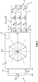
- Fig. 1 shows schematically a three-phase machine system 1 with a three-phase machine 3 designed as an asynchronous machine 2 on a converter 4 which has a plurality of electronic switches (not shown), for example semiconductor switches.
- the converter 4 is set up to output voltages with predetermined frequencies, amplitudes and (zero) phase angles at an output 6 by means of corresponding switching operations.
- the output 6 of the converter 4 is connected to the strands U, V, W of the asynchronous machine 2.
- the asynchronous machine 2 between the rotor 21 and the stator 20 see FIG Fig. 2 ) generates a rotating field that induces voltages in the rotor 21 of the asynchronous machine 2 and this through the resulting Rotor currents set in rotation.
- the asynchronous machine 2 is in Fig. 1 shown schematically as a circuit diagram.
- the asynchronous machine 2 has three strands U, V, W, each with a strand resistance R U , R V , R W and a strand inductance Lu, Lv, Lw.
- the voltages Eu, Ev, Ew denote the voltages induced in the stator 20 of the asynchronous machine 2 (Back EMF).
- the currents flowing in the strands of U, V, W currents Iu, Iv, I will be measured or with current measuring sensors 7a and / or 7b, a measuring device 8a or 8b determined W can. With the aid of the current measuring sensors 7b, string currents can also be determined, for example on the basis of a current flowing into the converter 4.
- a current measuring sensor 7a is provided in each branch U, V, W.
- the current measuring sensors 7a and 7b can be integrated into the converter 4 or be independent elements. With the aid of the current measuring sensors 7a and / or 7b, the temporal current profiles i U (t), i V (t), i W (t) of the currents Iu, Iv, Iw in the branches U, V, W can be determined.
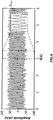
- Fig. 2 shows schematically an asynchronous machine 2 without windings in cross section with a stator 20, a rotor 21 and a slot 23, each on the rotor 21 and stator 20.
- An angular position ⁇ mech (t) of the rotor 21 is shown for illustration.
- the asynchronous machine 2 has asymmetries which can change temporally and spatially and thereby enable conclusions to be drawn about the angular position ⁇ mech (t) and / or the speed of the rotor 21.
- An example of such an asymmetry is the slot 23 of the rotor 21 and / or stator 20.
- Another example of an asymmetry is the saturation of the magnetic flux paths in the asynchronous machine 2.
- Both asymmetries cause temporal and spatial changes in inductance during operation of the asynchronous machine 2, which can be determined by evaluating the current curves i U (t), i V (t), i W (t).
- variable inductance components can therefore also be referred to as modulated inductances.
- the changes in the inductances L U , L V , L W can be caused, for example, by the grooves 23 of the rotor 21 or stator 20 and / or the magnetic saturation of magnetic iron paths in the three-phase machine 3.
- electrical signals preferably voltage signals U U (t), U V (t), U W (t) are connected to the strands U, V, W of the asynchronous machine 2 and the resulting current curves i U (t) , i V (t), i W (t) measured with the aid of the current measuring sensors 7.
- the voltages or voltage pulses applied by the converter 4 to operate the asynchronous machine 2 can be used as voltage signals U U (t), U V (t), U W (t).
- the electrical signals can contain excitation signals 9 to determine the operating state of the three-phase machine 3.
- the excitation signals 9 can be essentially independent of the generation of a rotating field of the three-phase machine 3.
- excitation signals 9 can be used, which are applied between the voltage (pulses) generated by the converter 4 to generate the rotating field or are superimposed on it. It is also possible to use voltage forms whose frequency is higher than that for generating the fundamental wave of the rotating field.
- Figures 10A to 10C the connection of an exemplary excitation signal 9 and the resulting current curves i U (t), i V (t), i W (t) in the branches U, V, W of a three-phase machine 3 are illustrated by way of illustration. Any ohmic resistances can be neglected here.
- the excitation signal 9 is shown normalized.
- di U / dt, di V / dt, di W in the strands U, V, W due to the relationship illustrated in equation (2) / dt a. Any ohmic resistances can usually be neglected here.
- the current values that is to say the amplitudes, respectively. Effective values, resp. Instantaneous values of the currents I U , I V , I W are used and linked.
- the linked signal ⁇ Saliency can also be referred to as a "saliency signal” (English “saliency”, “protruding”). If the signal ⁇ Saliency is calculated as a space vector, ⁇ Saliency represents a tensor.
- Figure 4A shows the trace of the tensor ⁇ Saliency , where both the abscissa and the ordinate have an amplitude in amperes / second designated.
- the abscissa represents the real part and the ordinate the imaginary part of the signal ⁇ Saliency .
- Figure 4B puts that in Figure 4A
- ⁇ Saliency contains three distinctive signal components.
- a first distinctive signal component is formed by a slot signal component ⁇ slot, which can be traced back to the slot 23 of the rotor 21 or of the stator 20 of the three-phase machine 3.
- a second distinctive signal component is formed by a saturation signal component ⁇ sat , which is due to the saturation of magnetic flux paths in the three-phase machine 3.
- a third distinctive signal component is formed by an intermodulation signal component ⁇ inter , which can be traced back to a physical link between the user signal component ⁇ slot and the saturation signal component ⁇ sat .
- the usage signal component ⁇ slot , the saturation signal component ⁇ sat and the intermodulation signal component ⁇ inter each have different fundamental frequencies.
- the intermodulation signal component ⁇ inter and the saturation signal component ⁇ sat were eliminated as interference signals and the slot signal component ⁇ slot was used to determine an angular position and / or a speed of the rotor.
- the slot signal component ⁇ slot is relatively small compared to other signal components. It can therefore be difficult, especially when the three-phase machine 3 is subjected to higher loads, to identify and extract the slot signal component ⁇ slot.
- the usage signal component ⁇ slot already has the order of magnitude of the higher harmonics of the saturation signal component ⁇ sat .
- the invention it is therefore provided not to use the slot signal component ⁇ slot directly to regulate the three-phase machine 3, but to use the intermodulation signal component ⁇ inter and its indirectly contained slot or rotor angle information to regulate the electrical three-phase machine 2.
- the method according to the invention can be used in a control unit 12 be executed (see Fig. 1 ).
- the intermodulation signal component ⁇ inter represents a dominant signal component in the signal ⁇ Saliency over a large speed range and can therefore be easily identified.
- the invention is based on the knowledge that there is a relationship between the fundamental frequency of the intermodulation signal component ⁇ inter and the fundamental frequency of the slot signal component ⁇ slot, which allows conclusions to be drawn about the angular position and / or speed of the rotor 21.
- ⁇ inter ⁇ ⁇ sat - ⁇ slot , are described, where ⁇ inter the fundamental frequency of the intermodulation signal component ⁇ inter , ⁇ sat the fundamental frequency of the saturation signal component ⁇ sat and ⁇ slot the fundamental frequency of the user signal component ⁇ slot means.
- the sign of ⁇ sat depends on the construction and type of the three-phase machine 3.
- the intermodulation signal component ⁇ inter is separated from other signal components, ie essentially isolated, for example by filtering or estimating the undesired signal components and subtraction.
- An angle ⁇ inter (t) is determined from the signal ⁇ inter , in particular from its fundamental frequency.
- the angle can be a phase angle that changes over time. This can be done, for example, with the aid of a PLL ("phase-locked loop").
- an angle, in particular a phase angle, ⁇ sat (t) of the saturation signal component ⁇ sat, in particular of its fundamental frequency is determined.
- ⁇ denotes angles
- ⁇ represent signals or signal components.
- the slot angle ⁇ slot (t) determined using equation (5) is essentially a calculated angle of the slot signal component ⁇ slot.
- ⁇ mech (t) can subsequently be used to control the three-phase machine 3, for example.
- electrical variables can be represented in a rotor-related coordinate system or the angular position (angular position control) and / or the speed (speed control) of the rotor can be controlled.
- Fig. 5 shows a time curve of the real component of the linked current signal ⁇ Saliency in seconds. This signal contains the slot signal component ⁇ slot, the saturation signal component ⁇ sat and the intermodulation signal component behind.
- Fig. 6 shows a time curve of the real part of the intermodulation signal component behind, in seconds, the usage signal component ⁇ slot and the saturation signal component ⁇ sat being eliminated.
- the signal shown still contains its own harmonics and harmonics of other signal components.
- Figures 7A-D show signal curves in different operating states of the asynchronous machine 2 at different times.
- the time t is plotted in seconds.
- the real part 10 and the imaginary part 11 of the intermodulation signal component ⁇ inter are shown.
- the mechanical speed ⁇ mech of the rotor 21 is shown in revolutions per minute (rpm) over time.
- Figure 7C shows the torque generated by the three-phase machine 3 in relation to a nominal torque over time.
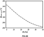
- the angle ⁇ inter (t) of the intermodulation signal component ⁇ inter depending on the load of the rotary electric machine 3, in particular of the torque M, by means of an intermodulation correction value ⁇ inter_corr is corrected.
- the dependence of ⁇ inter_corr on the torque M (in% based on the nominal torque) of the three-phase machine 3 is shown in Figure 8A shown.
- the angle ⁇ sat (t) of the saturation signal component ⁇ sat is corrected sat_corr depending on the load and the rotational speed of the rotary electric machine 3, in particular of the torque M by means of a saturation correction value ⁇ .
- the dependence of ⁇ sat_corr on the torque M (in% based on the nominal torque) of the three-phase machine 3 is shown in Figure 8B shown.
- the angle ⁇ inter of the intermodulation signal component ⁇ inter can also be dependent on the speed of the three-phase machine 3 (see FIG Figure 8C ). This dependency can also be taken into account with the aid of the intermodulation correction value ⁇ inter_corr, in addition or as an alternative to the torque dependency.
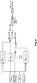
- Fig. 9 shows schematically a possible implementation of the method according to the invention.
- the intermodulation signal component ⁇ in-ter an electrical angle ⁇ ele (t), a torque M and a mechanical angular velocity ⁇ mech are used as input variables.
- ⁇ ele (t) represents the angle of the fundamental wave of the stator current and can be derived from the measured phase currents I U , I V , I W , for example as a space vector, to be determined.
- ⁇ mech can be determined from the intermodulation signal component ⁇ inter.
- the angle ⁇ sat (t) of the saturation signal component ⁇ sat can be obtained, which can be corrected using a previously determined saturation correction value ⁇ sat_corr.
- the angle ⁇ inter (t) of the intermodulation signal component ⁇ inter can be obtained from the intermodulation signal component ⁇ inter and corrected using an intermodulation correction value ⁇ inter_corr.
- the slot angle ⁇ slot (t) is calculated in a UNWRAP block to form a coherent angular curve ("unwrapped phase") and then divided by the number of slots N in the rotor to give a mechanical angular position ⁇ mech (t) of the rotor receive.
- the mechanical angular position can then be recalculated in a WRAP block so that ⁇ mech (t) is represented in an angular interval, in particular between [-180 °; 180 °] or [0 °; 360 °]. wrapped phase ").
- ⁇ mech (t) can then be used to control the three-phase machine 3.
Landscapes
- Engineering & Computer Science (AREA)
- Power Engineering (AREA)
- Databases & Information Systems (AREA)
- Control Of Ac Motors In General (AREA)
Priority Applications (5)
| Application Number | Priority Date | Filing Date | Title |
|---|---|---|---|
| EP20181490.2A EP3930177A1 (fr) | 2020-06-22 | 2020-06-22 | Procédé de régulation d'une machine à courant triphasée électrique ainsi que système de machine à courant triphasée pour un tel procédé |
| CN202110676372.6A CN113839590B (zh) | 2020-06-22 | 2021-06-18 | 调节旋转电流电机的方法和用于该方法的旋转电流机系统 |
| US17/351,965 US11594989B2 (en) | 2020-06-22 | 2021-06-18 | Method for regulating an electric rotary current machine, and rotary current machine system for such a method |
| ES21180719T ES3023271T3 (en) | 2020-06-22 | 2021-06-22 | Method for controlling an electric three-phase machine and three-phase machine system for such a method |
| EP21180719.3A EP3930178B1 (fr) | 2020-06-22 | 2021-06-22 | Procédé de régulation d'une machine électrique à courant triphasé ainsi que système de machine à courant triphasé pour un tel procédé |
Applications Claiming Priority (1)
| Application Number | Priority Date | Filing Date | Title |
|---|---|---|---|
| EP20181490.2A EP3930177A1 (fr) | 2020-06-22 | 2020-06-22 | Procédé de régulation d'une machine à courant triphasée électrique ainsi que système de machine à courant triphasée pour un tel procédé |
Publications (1)
| Publication Number | Publication Date |
|---|---|
| EP3930177A1 true EP3930177A1 (fr) | 2021-12-29 |
Family
ID=71130840
Family Applications (2)
| Application Number | Title | Priority Date | Filing Date |
|---|---|---|---|
| EP20181490.2A Withdrawn EP3930177A1 (fr) | 2020-06-22 | 2020-06-22 | Procédé de régulation d'une machine à courant triphasée électrique ainsi que système de machine à courant triphasée pour un tel procédé |
| EP21180719.3A Active EP3930178B1 (fr) | 2020-06-22 | 2021-06-22 | Procédé de régulation d'une machine électrique à courant triphasé ainsi que système de machine à courant triphasé pour un tel procédé |
Family Applications After (1)
| Application Number | Title | Priority Date | Filing Date |
|---|---|---|---|
| EP21180719.3A Active EP3930178B1 (fr) | 2020-06-22 | 2021-06-22 | Procédé de régulation d'une machine électrique à courant triphasé ainsi que système de machine à courant triphasé pour un tel procédé |
Country Status (4)
| Country | Link |
|---|---|
| US (1) | US11594989B2 (fr) |
| EP (2) | EP3930177A1 (fr) |
| CN (1) | CN113839590B (fr) |
| ES (1) | ES3023271T3 (fr) |
Citations (1)
| Publication number | Priority date | Publication date | Assignee | Title |
|---|---|---|---|---|
| WO1999039430A1 (fr) | 1998-01-30 | 1999-08-05 | Schroedl Manfred | Procede et reglage d'un moteur a courant triphase depourvu de capteur mecanique de rotation |
Family Cites Families (6)
| Publication number | Priority date | Publication date | Assignee | Title |
|---|---|---|---|---|
| CN101902190B (zh) * | 2010-07-28 | 2012-07-04 | 南京航空航天大学 | 一种开关磁阻电机无位置传感器转子位置估计方法 |
| CN102201770A (zh) * | 2011-05-30 | 2011-09-28 | 重庆大学 | 一种注入谐波电压抑制永磁同步电机谐波电流的控制方法 |
| JP2014093821A (ja) * | 2012-11-01 | 2014-05-19 | Toyota Motor Corp | モータおよびロータ回転角度検出装置 |
| US9871418B2 (en) * | 2012-11-01 | 2018-01-16 | General Electric Company | Sensorless electric machine |
| CN103701391B (zh) * | 2013-12-09 | 2015-10-21 | 浙江大学 | 基于槽谐波提取的异步电机转速快速辨识方法 |
| WO2017212794A1 (fr) * | 2016-06-08 | 2017-12-14 | 三菱電機株式会社 | Appareil d'estimation de vitesse pour moteur en ca, appareil d'entraînement pour moteur en ca, compresseur de réfrigérant, et appareil de cycle de congélation |
-
2020
- 2020-06-22 EP EP20181490.2A patent/EP3930177A1/fr not_active Withdrawn
-
2021
- 2021-06-18 CN CN202110676372.6A patent/CN113839590B/zh active Active
- 2021-06-18 US US17/351,965 patent/US11594989B2/en active Active
- 2021-06-22 ES ES21180719T patent/ES3023271T3/es active Active
- 2021-06-22 EP EP21180719.3A patent/EP3930178B1/fr active Active
Patent Citations (1)
| Publication number | Priority date | Publication date | Assignee | Title |
|---|---|---|---|---|
| WO1999039430A1 (fr) | 1998-01-30 | 1999-08-05 | Schroedl Manfred | Procede et reglage d'un moteur a courant triphase depourvu de capteur mecanique de rotation |
Non-Patent Citations (4)
| Title |
|---|
| BROWNIAN PATERSONROBERT D. LORENZ, INDUCTION MACHINE DESIGN METHODOLOGY FOR SELF-SENSING: BALANCING SALIENCIES AND POWER CONVERSION PROPERTIES |
| METWALY MOHAMED K ET AL: "Slotting Saliency Extraction For Sensorless Torque Control of Standard Induction Machines", IEEE TRANSACTIONS ON ENERGY CONVERSION, IEEE SERVICE CENTER, PISCATAWAY, NJ, US, vol. 33, no. 1, 1 March 2018 (2018-03-01), pages 68 - 77, XP011677884, ISSN: 0885-8969, [retrieved on 20180215], DOI: 10.1109/TEC.2017.2726998 * |
| W. FAHRNERM.A. VOGELSBERGERT. WOLBANK, IDENTIFICATION AND COMPENSATION OF HIGH-ORDER HARMONIC DISTORTIONS IN SALIENCY BASED SENSORLESS CONTROL OF INDUCTION MACHINES |
| WOLBANK T M ET AL: "Comparison of inherent saliency tracking methods for zero speed sensorless control of standard induction machines", ELECTRIC MACHINES AND DRIVES CONFERENCE, 2009. IEMDC '09. IEEE INTERNATIONAL, IEEE, PISCATAWAY, NJ, USA, 3 May 2009 (2009-05-03), pages 1258 - 1263, XP031475932, ISBN: 978-1-4244-4251-5 * |
Also Published As
| Publication number | Publication date |
|---|---|
| US20210399661A1 (en) | 2021-12-23 |
| ES3023271T3 (en) | 2025-05-30 |
| CN113839590B (zh) | 2024-11-08 |
| EP3930178B1 (fr) | 2025-03-26 |
| EP3930178A1 (fr) | 2021-12-29 |
| US11594989B2 (en) | 2023-02-28 |
| CN113839590A (zh) | 2021-12-24 |
Similar Documents
| Publication | Publication Date | Title |
|---|---|---|
| EP0579694B1 (fr) | Procede et circuits pour determiner des variables d'etat electromagnetiques et mecaniques liees a la machine sur des generateurs a induction electrodynamiques alimentes par l'intermediaire de convertisseurs | |
| EP1985007B1 (fr) | Procede et dispositif de fonctionnement d'une machine synchrone | |
| EP0539401B1 (fr) | Procede et circuit de detection, sans capteurs, de la position angulaire d'une machine synchrone sans amortisseur, de preference excitee par un aimant permanent, alimentee par convertisseur | |
| EP2421146A1 (fr) | Dispositif et procédé d'identification des paramètres de référence magnéto-mécaniques d'un moteur synchrone triphasé sans utilisation d'encodeur de vitesse | |
| AT508854B1 (de) | Verfahren zur mechanisch sensorlosen regelung einer drehstrommaschine | |
| DE102012212766A1 (de) | Verfahren zur Bestimmung der Rotorlage eines elektronisch kommutierten mehrphasigen Gleichstrommotors | |
| DE102016203273A1 (de) | Verfahren und Anordnung zur Überwachung eines Rotorpositionssensors einer PSM-Maschine | |
| EP2194641A1 (fr) | Système de détermination de la position initiale des pôles d'un engrenage d'électromoteur | |
| EP2226929B1 (fr) | Système de surveillance de la plausibilité pour des mesures de mouvements sur un dispositif d'entraînement électrique | |
| DE3724117A1 (de) | Steuereinrichtung fuer induktionsmotoren | |
| DE112022003208T5 (de) | System und Verfahren zur Berechnung eines resultierenden Direkt-Quadratur-Null-Vektors für einen Antrieb unter Verwendung einer Rotorposition | |
| DE102009011674A1 (de) | Verfahren und Vorrichtung zum Betreiben einer elektrischen Maschine | |
| EP2619899B1 (fr) | Procédé et dispositif de détermination, sans l'aide de capteur, d'une position d'un rotor d'une machine électrique | |
| EP3017536B1 (fr) | Procédé et dispositif de détermination, sans l'aide de capteur, d'une position d'un rotor d'une machine électrique | |
| WO2019120617A1 (fr) | Procédé de détermination, sans capteur de rotation, de l'orientation d'un rotor d'une machine à champ tournant et dispositif de régulation sans capteur de rotation d'un moteur triphasé | |
| EP3857704B1 (fr) | Procédé pour déterminer une valeur de correction décrivant une différence angulaire entre une position supposée et une position réelle un axe d, unité de commande, onduleur, véhicule et programme d'ordinateur | |
| EP3930178B1 (fr) | Procédé de régulation d'une machine électrique à courant triphasé ainsi que système de machine à courant triphasé pour un tel procédé | |
| EP3723273B1 (fr) | Procédé de détermination de la position du rotor | |
| EP3529890B1 (fr) | Système de réglage d'une machine synchrone et procédé pour faire fonctionner une machine synchrone | |
| EP3704790B1 (fr) | Procédé de détermination de la position du rotor de machines électriques synchrones sans capteur mécanique | |
| DE10327615B4 (de) | Verfahren zur Ermittlung der Sättigungscharakteristik einer Streuinduktivität einer Asynchronmaschine | |
| AT395487B (de) | Verfahren und schaltungsanordnung zur sensorlosen drehwinkelerfassung einer daempferlosen, vorzugsweise permanentmagneterregten, ueber einen stromrichter gespeisten synchronmaschine | |
| DE10114293B3 (de) | Verfahren zum Betreiben einer Drehfeldmaschine | |
| DE102013218122A1 (de) | Elektronisch kommutierte elektrische Maschine sowie Verfahren zum Betreiben einer elektrischen Maschine | |
| AT399602B (de) | Verfahren und schaltungsanordnung zur rotorlage- bestimmung und zur momentenaufbringung an einer über einen umrichter gespeisten reluktanzmaschine |
Legal Events
| Date | Code | Title | Description |
|---|---|---|---|
| PUAI | Public reference made under article 153(3) epc to a published international application that has entered the european phase |
Free format text: ORIGINAL CODE: 0009012 |
|
| STAA | Information on the status of an ep patent application or granted ep patent |
Free format text: STATUS: THE APPLICATION HAS BEEN PUBLISHED |
|
| AK | Designated contracting states |
Kind code of ref document: A1 Designated state(s): AL AT BE BG CH CY CZ DE DK EE ES FI FR GB GR HR HU IE IS IT LI LT LU LV MC MK MT NL NO PL PT RO RS SE SI SK SM TR |
|
| B565 | Issuance of search results under rule 164(2) epc |
Effective date: 20201211 |
|
| STAA | Information on the status of an ep patent application or granted ep patent |
Free format text: STATUS: THE APPLICATION IS DEEMED TO BE WITHDRAWN |
|
| 18D | Application deemed to be withdrawn |
Effective date: 20220630 |