EP3930367B1 - Procédé et appareil de commande de mesure, terminal et dispositif de réseau - Google Patents
Procédé et appareil de commande de mesure, terminal et dispositif de réseau Download PDFInfo
- Publication number
- EP3930367B1 EP3930367B1 EP19931676.1A EP19931676A EP3930367B1 EP 3930367 B1 EP3930367 B1 EP 3930367B1 EP 19931676 A EP19931676 A EP 19931676A EP 3930367 B1 EP3930367 B1 EP 3930367B1
- Authority
- EP
- European Patent Office
- Prior art keywords
- measurement
- srs
- network device
- terminal
- cli
- Prior art date
- Legal status (The legal status is an assumption and is not a legal conclusion. Google has not performed a legal analysis and makes no representation as to the accuracy of the status listed.)
- Active
Links
Images


Classifications
-
- H—ELECTRICITY
- H04—ELECTRIC COMMUNICATION TECHNIQUE
- H04B—TRANSMISSION
- H04B17/00—Monitoring; Testing
- H04B17/30—Monitoring; Testing of propagation channels
- H04B17/309—Measuring or estimating channel quality parameters
- H04B17/345—Interference values
-
- H—ELECTRICITY
- H04—ELECTRIC COMMUNICATION TECHNIQUE
- H04B—TRANSMISSION
- H04B17/00—Monitoring; Testing
- H04B17/30—Monitoring; Testing of propagation channels
- H04B17/309—Measuring or estimating channel quality parameters
- H04B17/318—Received signal strength
-
- H—ELECTRICITY
- H04—ELECTRIC COMMUNICATION TECHNIQUE
- H04B—TRANSMISSION
- H04B17/00—Monitoring; Testing
- H04B17/30—Monitoring; Testing of propagation channels
- H04B17/309—Measuring or estimating channel quality parameters
- H04B17/318—Received signal strength
- H04B17/327—Received signal code power [RSCP]
-
- H—ELECTRICITY
- H04—ELECTRIC COMMUNICATION TECHNIQUE
- H04B—TRANSMISSION
- H04B17/00—Monitoring; Testing
- H04B17/30—Monitoring; Testing of propagation channels
- H04B17/309—Measuring or estimating channel quality parameters
- H04B17/336—Signal-to-interference ratio [SIR] or carrier-to-interference ratio [CIR]
-
- H—ELECTRICITY
- H04—ELECTRIC COMMUNICATION TECHNIQUE
- H04L—TRANSMISSION OF DIGITAL INFORMATION, e.g. TELEGRAPHIC COMMUNICATION
- H04L5/00—Arrangements affording multiple use of the transmission path
- H04L5/003—Arrangements for allocating sub-channels of the transmission path
- H04L5/0048—Allocation of pilot signals, i.e. of signals known to the receiver
-
- H—ELECTRICITY
- H04—ELECTRIC COMMUNICATION TECHNIQUE
- H04W—WIRELESS COMMUNICATION NETWORKS
- H04W24/00—Supervisory, monitoring or testing arrangements
- H04W24/02—Arrangements for optimising operational condition
-
- H—ELECTRICITY
- H04—ELECTRIC COMMUNICATION TECHNIQUE
- H04W—WIRELESS COMMUNICATION NETWORKS
- H04W24/00—Supervisory, monitoring or testing arrangements
- H04W24/08—Testing, supervising or monitoring using real traffic
-
- H—ELECTRICITY
- H04—ELECTRIC COMMUNICATION TECHNIQUE
- H04W—WIRELESS COMMUNICATION NETWORKS
- H04W24/00—Supervisory, monitoring or testing arrangements
- H04W24/10—Scheduling measurement reports ; Arrangements for measurement reports
-
- H—ELECTRICITY
- H04—ELECTRIC COMMUNICATION TECHNIQUE
- H04W—WIRELESS COMMUNICATION NETWORKS
- H04W52/00—Power management, e.g. Transmission Power Control [TPC] or power classes
- H04W52/02—Power saving arrangements
- H04W52/0209—Power saving arrangements in terminal devices
- H04W52/0212—Power saving arrangements in terminal devices managed by the network, e.g. network or access point is leader and terminal is follower
-
- H—ELECTRICITY
- H04—ELECTRIC COMMUNICATION TECHNIQUE
- H04L—TRANSMISSION OF DIGITAL INFORMATION, e.g. TELEGRAPHIC COMMUNICATION
- H04L43/00—Arrangements for monitoring or testing data switching networks
- H04L43/16—Threshold monitoring
-
- Y—GENERAL TAGGING OF NEW TECHNOLOGICAL DEVELOPMENTS; GENERAL TAGGING OF CROSS-SECTIONAL TECHNOLOGIES SPANNING OVER SEVERAL SECTIONS OF THE IPC; TECHNICAL SUBJECTS COVERED BY FORMER USPC CROSS-REFERENCE ART COLLECTIONS [XRACs] AND DIGESTS
- Y02—TECHNOLOGIES OR APPLICATIONS FOR MITIGATION OR ADAPTATION AGAINST CLIMATE CHANGE
- Y02D—CLIMATE CHANGE MITIGATION TECHNOLOGIES IN INFORMATION AND COMMUNICATION TECHNOLOGIES [ICT], I.E. INFORMATION AND COMMUNICATION TECHNOLOGIES AIMING AT THE REDUCTION OF THEIR OWN ENERGY USE
- Y02D30/00—Reducing energy consumption in communication networks
- Y02D30/70—Reducing energy consumption in communication networks in wireless communication networks
Definitions
- Embodiments of the present disclosure relate to the technical field of mobile communications, and in particular to a method and an apparatus for controlling measurement, a terminal, and a network device.
- WO2019/032031A1 discloses systems and methods for reducing cross-link interference in a wireless system.
- a method of operation of a wireless device in a wireless system comprises receiving, from a serving Access Point (AP), wireless device specific Sounding Reference Signal (SRS) or Demodulation Reference Signal (DMRS) configuration information for one or more potential aggressor wireless devices.
- the method further comprises performing one or more measurements on at least one of the one or more potential aggressor wireless devices using the wireless device specific SRS or DMRS configuration information for the at least one of the one or more potential aggressor wireless devices and reporting at least one of the one or more measurements to the serving AP. In this manner, cross-link interference measurement and reporting is enabled.
- SRS Sounding Reference Signal
- DMRS Demodulation Reference Signal
- Interference may occur between two terminals located in different cells, and such interference is referred to as cross-link interference (CLI).
- CLI cross-link interference
- UE-to-UE user equipment to user equipment
- the CLI measurement means that a terminal measures a sounding reference signal (SRS) of another terminal to discover interference. How to control the performance of such the CLI measurement and reporting of a measurement result is a problem to be solved.
- SRS sounding reference signal
- a method as set forth in claim 1 there is provided a method as set forth in claim 1.
- an apparatus as set forth in claim 5.
- a terminal as set forth in claim 9.
- a chip as set forth in claim 10.
- a computer-readable storage medium as set forth in claim 11.
- the embodiments of the present disclosure provide a method for controlling measurement, which includes that:
- the embodiments of the present disclosure provide an apparatus for controlling measurement, which includes:
- the embodiments of the present disclosure provide a terminal, which includes a processor and a memory, herein the memory is configured to store a computer program, and the processor is configured to invoke and run the computer program stored in the memory to perform the above-described method for controlling measurement.
- the present disclosure provides a network device, which includes a processor and a memory, herein the memory is configured to store a computer program, and the processor is configured to invoke and run the computer program stored in the memory to perform the above-described method for controlling measurement.
- the embodiments of the present disclosure provide a chip configured to perform the above-described method for controlling measurement.
- the chip includes a processor configured to invoke and run a computer program from a memory to cause a device on which the chip is mounted to perform the above-described method for controlling measurement.
- the embodiments of the present disclosure provide a computer-readable storage medium having stored therein a computer program that, when executed by a computer, causes the computer to perform the above-described method for controlling measurement.
- the present disclosure provides a computer program product, including one or more computer program instructions that cause a computer to perform the above-described method for controlling measurement.
- the present disclosure provides a computer program that, when executed by a computer, causes the computer to perform the above-described method for controlling measurement.
- GSM Global System of Mobile Communication
- CDMA Code Division Multiple Access
- WCDMA Wideband Code Division Multiple Access
- GPRS General Packet Radio Service
- LTE Long Term Evolution
- FDD Frequency Division Duplex
- TDD Time Division Duplex
- UMTS Universal Mobile Telecommunication System
- WiMAX Worldwide Interoperability for Microwave Access
- the communication system 100 may include a network device 110, which may be a device in communication with a terminal 120 (or referred to as a communication terminal, or a terminal).
- the network device 110 may provide communication coverage for a particular geographic area and may communicate with terminals located within the coverage area.
- the network device 110 may be a base transceiver station (BTS) in a GSM system or a CDMA system, or a NodeB (NB) in a WCDMA system, an Evolutional Node B (eNB or eNodeB) in an LTE system, or a radio controller in a cloud radio access network (CRAN), or the network device may be a mobile switching center, a relay station, an access point, a vehicle-mounted device, a wearable device, a hub, a switch, a bridge, a router, a network-side device in a 5G network, a network device in a future evolved public land mobile network (PLMN), or the like.
- BTS base transceiver station
- NB NodeB
- eNB or eNodeB Evolutional Node B
- CRAN cloud radio access network
- the network device may be a mobile switching center, a relay station, an access point, a vehicle-mounted device, a wearable device, a hub, a switch
- the communication system 100 further includes at least one terminal 120 located within the coverage of the network device 110.
- Terminal includes but is not limited to an apparatus that is configured to receive or send communication signals via wired line connections, such as via Public Switched Telephone Networks (PSTN), Digital Subscriber Lines (DSL), digital cables, direct cable connections and/or another data connections/networks; and/or via wireless interfaces, such as wireless interfaces configured for cellular networks, wireless local area networks (WLAN), like digital TV network of DVB-H networks, satellite networks, AM-FM broadcast transmitters and/or another terminal and/or Internet of Things (IoT) device.
- PSTN Public Switched Telephone Networks
- DSL Digital Subscriber Lines
- WLAN wireless local area networks
- IoT Internet of Things
- a terminal set to communicate via a wireless interface may be referred to as a "wireless communication terminal", a “wireless terminal” or a “mobile terminal”.
- mobile terminals include but are not limited to satellites or cellular phones; Personal Communications System (PCS) terminals that can combine cellular radio phones with data processing, fax, and data communication capabilities; PDA that includes radio phones, pagers, Internet/intranet access, Web browser, memo pad, calendar, and/or Global Positioning System (GPS) receiver; and conventional laptop and/or palmtop receivers or other electronic apparatuses including radio telephone transceivers.
- PCS Personal Communications System
- GPS Global Positioning System
- the terminal may refer to access terminals, user equipment (UE), user units, user stations, mobile stations, mobile platforms, remote stations, remote terminals, mobile device, user terminals, terminals, wireless communication device, user agents or user apparatuses.
- the access terminals may be cellular phones, cordless phones, Session Initiation Protocol (SIP) phones, Wireless Local Loop (WLL) stations, personal digital assistants (PDA), handheld devices with wireless communication functions, computing devices or other processing devices connected to wireless modems, in-vehicle devices, wearable devices, terminals in 5G networks, or terminals in the future enhanced PLMN, etc.
- a Device to Device (D2D) communication may be performed between terminals 120.
- D2D Device to Device
- the 5G system or the 5G network may also be referred to as a new wireless (NR) system or an NR network.
- NR new wireless
- the communication system 100 may include a plurality of network devices and other numbers of terminals may be included within a coverage area of each network device, which is not limited in the embodiment of the present disclosure.
- the communication system 100 may further include a network controller, a mobility management entity, and other network entities, which are not limited in the embodiment of the present disclosure.
- a device having a communication function in a network/system in the embodiments of the present disclosure may be referred to as a communication device.
- the communication device may include a network device 110 and terminals 120 having communication functions.
- the network device 110 and the terminals 120 may be specific devices described above, and details are not described herein.
- the communication device may further include other devices in the communication system 100, such as a network controller, a mobility management entity, and other network entities, which are not limited in the embodiment of the present disclosure.
- CLI Between two terminals located in different cells, there may be interference with each other, which is called CLI.
- CLI For example, at the edges of two cells (a cell 1 and a cell 2, respectively), there are two terminals (a terminal 1 and a terminal 2, respectively), herein the terminal 1 is located in the cell 1 and the terminal 2 is located in the cell 2.
- the uplink transmission of the terminal 1 may correspond to the downlink reception of the terminal 2, resulting in the uplink transmission of the terminal 1 interfering with the downlink reception of the terminal 2, which causes the CLI between the terminal 1 and the terminal 2.
- the ratio of Up Link (UL) to Down Link (DL) may be statically configured or dynamically configured.
- the Release 15 (R15) NR specification supports mechanisms that allow dynamic DL/UL allocation. However, without specifying any mitigation techniques and coexistence requirements for the CLI, the use of dynamic DL/UL allocation operations is greatly limited. The flexibility of duplexing with the capability of preventing CLI provides better user throughput than static UL/DL operations or dynamic UL/DL operations without the capability of preventing interference.
- the R16 agrees to introduce UE-to-UE measurement for the CLI
- the UE-to-UE measurement refers to the CLI measurement in the following embodiments of the present disclosure.
- the CLI measurement mainly refers to that the terminal measures the SRS of another terminal to discover interference.
- the terminals located at the center of the cell will have CLI problems, so it is not necessary for the terminals located at the center of the cell to perform the CLI measurement and the reporting of the measurement results, otherwise a problem of electricity consumption will occur.
- How to effectively control the execution of the CLI measurement and the reporting of the measurement result is a problem to be solved. To solve this problem, the following technical solutions of the embodiments of the present disclosure are proposed.
- FIG. 2 is a first flowchart of an example method for controlling measurement and may be useful as background for understanding the present disclosure. As shown in FIG. 2 , the method for controlling measurement includes the following operations.
- a terminal receives a first control parameter from a network device.
- the terminal is any device capable of communicating with a network, such as a mobile phone, a tablet computer, a notebook, a vehicle-mounted terminal, or a wearable device.
- the network device may be a base station.
- the first control parameter is used by the terminal to determine at least one of: whether the CLI measurement configuration is valid, or whether to perform the CLI measurement.
- the CLI measurement configuration refers to a measurement configuration associated with the CLI
- the CLI measurement configuration includes at least one SRS resource configuration, each of the at least one SRS resource configuration is associated with at least one of a cell identity or an SRS index.
- the cell identity associated with the SRS resource configuration is used for identifying a cell configured with the SRS resource configuration
- the SRS index associated with the SRS resource configuration is used for identifying an SRS corresponding to the SRS resource configuration.
- the CLI measurement configuration includes three SRS resource configurations, namely, an SRS resource configuration 1, an SRS resource configuration 2 and an SRS resource configuration 3.
- the SRS resource configuration 1 is associated with the cell 1 and an SRS1
- the SRS resource configuration 2 is associated with the cell 1 and an SRS2
- the SRS resource configuration 3 is associated with the cell 2 and an SRS3.
- the cell 1 is configured with the SRS resource configuration 1 and the SRS resource configuration 2
- the cell 2 is configured with the SRS resource configuration 3.
- the SRS resource configuration 1 corresponds to the resource configuration of the SRS1
- the SRS resource configuration 2 corresponds to the resource configuration of the SRS2
- the SRS resource configuration 3 corresponds to the resource configuration of the SRS3.
- the base station may deliver multiple SRS resource configurations (i.e., CLI measurement configuration) that multiple cells (which may be different cells within the same base station, or may be different cells within different base stations) are configured with to the terminal.
- the terminal determines, based on a signal quality of a first cell and the first control parameter, at least one of: whether a CLI measurement configuration is valid, or whether to perform a CLI measurement, herein the CLI measurement refers to that the terminal measures an SRS of another terminal.
- the first control parameter may be implemented in the following two manners.
- the first control parameter is a first measurement threshold
- the first measurement threshold is an execution control parameter of CLI measurement.
- the terminal measures a signal quality of a serving cell; when the signal quality of the serving cell is less than the first measurement threshold, the terminal performs CLI measurement for a CLI measurement configuration; or when the signal quality of the serving cell is greater than or equal to the first measurement threshold, the terminal stops the CLI measurement for a CLI measurement configuration.
- the signal quality includes at least one of a reference signal received power (RSRP), a reference signal received quality (RSRQ), or a signal to interference plus noise ratio (SINR).
- RSRP reference signal received power
- RSRQ reference signal received quality
- SINR signal to interference plus noise ratio
- the first measurement threshold includes at least one of an RSRP threshold, an RSRQ threshold, or an SINR threshold.
- the first control parameter is a second measurement threshold
- the second measurement threshold is associated with a cell identity of a neighboring cell
- the second measurement threshold is a validity control parameter of a CLI measurement configuration
- the terminal measures a signal quality of a neighboring cell; when the signal quality of the neighboring cell is greater than or equal to the second measurement threshold, the terminal determines that the CLI measurement configuration associated with the cell identity is valid; or when the signal quality of the neighboring cell is less than the second measurement threshold, the terminal determines that the CLI measurement configuration associated with the cell identity is invalid.
- the signal quality includes at least one of an RSRP, an RSRQ or an SINR.
- the second measurement threshold includes at least one of an RSRP threshold, an RSRQ threshold or an SINR threshold.
- the terminal performs CLI measurement for the CLI measurement configuration when the CLI measurement configuration is valid; or the terminal stops the CLI measurement for the CLI measurement configuration when the CLI measurement configuration is invalid.
- the network device delivers the first control parameter to the terminal, and according to the measurement result and the first control parameter, the terminal determines at least one of: whether the CLI measurement configuration is valid, or whether to perform the CLI measurement, thereby effectively controlling the execution of the CLI measurement.
- FIG. 3 is a second flowchart of a method for controlling measurement and may be useful as background for understanding the present disclosure. As shown in FIG. 3 , the method for controlling measurement includes the following operations.
- a network device configures a CLI measurement configuration for a terminal.
- the network device may be a base station.
- the terminal is any device capable of communicating with a network, such as a mobile phone, a tablet computer, a notebook, a vehicle-mounted terminal, or a wearable device.
- the CLI measurement configuration refers to a measurement configuration associated with the CLI
- the CLI measurement configuration includes at least one SRS resource configuration, each of the at least one SRS resource configuration is associated with at least one of a cell identity or an SRS index.
- the cell identity associated with the SRS resource configuration is used for identifying a cell configured with the SRS resource configuration
- the SRS index associated with the SRS resource configuration is used for identifying the SRS corresponding to the SRS resource configuration.
- the base station may deliver multiple SRS resource configurations (i.e., CLI measurement configurations) that multiple cells (which may be different cells within the same base station, or may be different cells within different base stations) are configured with to the terminal.
- the SRS index is unique within the CLI measurement configuration or is unique within the cell identity.
- the network device receives a measurement result from the terminal, and determines whether to deactivate or activate the CLI measurement configuration according to the measurement result.
- the measurement result sent by the terminal may be implemented by a measurement report, i.e., MeasurmentReport.
- the measurement result sent by the terminal is used by the network device to determine whether to deactivate or activate the CLI measurement configuration.
- the network device may determine whether to deactivate or activate the CLI measurement configuration in following two manners.
- the network device receives a measurement result of the serving cell sent by the terminal; when the measurement result of the serving cell is less than a first measurement threshold, the network device determines to activate the CLI measurement configuration; or when the measurement result of the serving cell is greater than or equal to a first measurement threshold, the network device determines to deactivate the CLI measurement configuration.
- the measurement result includes a measurement result of at least one of the following signal quality: an RSRP, an RSRQ or an SINR.
- the network device receives a measurement result of the neighboring cell sent by the terminal; when a signal quality of the neighboring cell is greater than or equal to a second measurement threshold, the network device determines to activate the CLI measurement configuration; or when a signal quality of the neighboring cell is less than a second measurement threshold, the network device determines to deactivate the CLI measurement configuration.
- the measurement result includes a measurement result of at least one of the following signal quality: an RSRP, an RSRQ or an SINR.
- the network device sends a deactivation instruction or an activation instruction of the CLI measurement configuration to the terminal, and the deactivation instruction or the activation instruction is carried in one of the following: a radio resource control (RRC) signaling, a media access control control element (MAC CE), or a physical downlink control channel (PDCCH).
- RRC radio resource control
- MAC CE media access control control element
- PDCCH physical downlink control channel
- the deactivation instruction or the activation instruction carries at least one of an identifier of a CLI measurement configuration, a cell identity, or an SRS index.
- the information carried in the deactivation instruction or the activation instruction is used by the terminal to determine which CLI measurement configuration or which part of the CLI measurement configuration is deactivated or activated.
- the CLI measurement configuration after the terminal activates the CLI measurement configuration, the CLI measurement configuration is in a valid state; after the terminal deactivates the CLI measurement configuration, the CLI measurement configuration is in an invalid state.
- the terminal reports the measurement result to the network device, and the network device determines whether to deactivate or activate the CLI measurement configuration according to the measurement result, thereby effectively controlling the execution of the CLI measurement on the terminal side.
- FIG. 4 is a third flowchart of a method for controlling measurement according to an embodiment of the present disclosure. As shown in FIG. 4 , the method for controlling measurement includes the following operations.
- a terminal receives a CLI measurement configuration from a network device, herein the CLI measurement configuration includes at least one SRS resource configuration, each of the at least one SRS resource configuration is associated with at least one of a cell identity or an SRS index.
- the terminal is any device capable of communicating with a network, such as a mobile phone, a tablet computer, a notebook, a vehicle-mounted terminal, or a wearable device.
- the network device may be a base station.
- the CLI measurement configuration refers to a measurement configuration associated with the CLI.
- the CLI measurement configuration includes at least one SRS resource configuration, each of the at least one SRS resource configuration is associated with at least one of a cell identity or an SRS index.
- the cell identity associated with the SRS resource configuration is used for identifying a cell configured with the SRS resource configuration
- the SRS index associated with the SRS resource configuration is used for identifying an SRS corresponding to the SRS resource configuration.
- the base station may deliver multiple SRS resource configurations (i.e., CLI measurement configurations) that multiple cells (which may be different cells within the same base station, or may be different cells within different base stations) are configured with to the terminal.
- the network device delivers a CLI measurement configuration to the terminal via a dedicated signaling, such as an RRC signaling.
- the CLI measurement configuration may have the following implementation manners.
- the terminal performs a CLI measurement according to the CLI measurement configuration, herein the CLI measurement refers to that the terminal measures an SRS of another terminal.
- the measurement result meets a threshold condition configured by the network device includes that: the measurement result is greater than or equal to a first threshold configured by the network device; or the measurement result is less than or equal to a first threshold configured by the network device.
- the terminal compares the measurement result of an SRS with a first threshold configured by the network device; 1) when the measurement result is greater than or equal to the first threshold, the terminal waits for time T; if the measurement result is still greater than or equal to the first threshold within the time T, the terminal triggers reporting of the measurement result; or 2) when the measurement result is less than or equal to the first threshold, the terminal waits for time T; if the measurement result is still less than or equal to the first threshold within the time T; the terminal triggers reporting of the measurement result.
- the T may be 0 or a non-0 positive number.
- a content reported by the terminal to the network device includes at least one of a measurement result of an SRS-RSRP, a measurement result of an SRS-RSRQ, or a measurement result of an SRS-SINR associated with an identifier of each CLI measurement configuration.
- the terminal performs measurement according to the set of SRS resource configurations to obtain measurement results of a set of SRSs; when a measurement result of at least one SRS in the measurement results of the set of SRSs meets the threshold condition configured by the network device, the terminal waits for time T; if the measurement result still meets the threshold condition within the time T, the terminal reports the measurement result to the network device, herein the value of the T is greater than or equal to 0.
- the measurement result meets a threshold condition configured by the network device includes that: the measurement result is greater than or equal to a first threshold configured by the network device; or the measurement result is less than or equal to a first threshold configured by the network device.
- the terminal compares measurement results of a set of SRSs with a first threshold configured by the network device: 1) when the measurement result of at least one SRS is greater than or equal to the first threshold, the terminal waits for time T; if the measurement result is still greater than or equal to the first threshold within the time T, the terminal triggers reporting of the measurement result; or 2) when the measurement result of at least one SRS is less than or equal to the first threshold, the terminal waits for time T; if the measurement result is still less than or equal to the first threshold within the time T, the terminal triggers reporting of the measurement result.
- T may be 0 or a non-0 positive number.
- the content reported by the terminal to the network device includes at least one of a measurement result of an SRS-RSRP, a measurement result of an SRS-RSRQ or a measurement result of an SRS-SINR associated with each SRS index; or a list of SRS indexes whose measurement results meet a threshold condition configured by the network device, for example, a list of SRS indexes whose measurement results are greater than or equal to a first threshold or a list of SRS indexes whose measurement results are less than or equal to a first threshold.
- the content reported by the terminal to the network device further includes a cell identity associated with a measurement result of the SRS, and the cell identity is identical to a cell identity associated with an SRS resource configuration corresponding to the measurement result.
- the content reported by the terminal to the network device further includes a measurement identifier associated with the measurement configuration of the SRS.
- the measurement configuration of the SRS refers to a measurement configuration related to the SRS in the CLI measurement configuration.
- the measurement configuration of the SRS includes a resource configuration of the SRS.
- how the network device configures the CLI measurement configuration for the terminal is clarified, and how the terminal triggers the reporting of the measurement result and the specific content of the reporting are clarified.
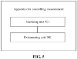
- FIG. 5 is a first schematic structural diagram of an apparatus for controlling measurement according to an embodiment of the present disclosure. As shown in FIG. 5 , the apparatus for controlling measurement includes a receiving unit 501 and a determining unit 502.
- the receiving unit 501 is configured to receive a first control parameter from a network device.
- the determining unit 502 is configured to: based on a signal quality of a first cell and the first control parameter, determine at least one of: whether a CLI measurement configuration is valid, or whether to perform a CLI measurement, here the CLI measurement refers to that the terminal measures an SRS of another terminal.
- the first control parameter is a first measurement threshold.
- the determining unit 502 is configured to measure a signal quality of a serving cell; when the signal quality of the serving cell is less than the first measurement threshold, perform CLI measurement for a CLI measurement configuration; or when the signal quality of the serving cell is greater than or equal to the first measurement threshold, stop CLI measurement for a CLI measurement configuration.
- the first control parameter is a second measurement threshold, herein the second measurement threshold is associated with a cell identity of a neighboring cell.
- the determining unit 502 is configured to measure a signal quality of a neighboring cell; when the signal quality of the neighboring cell is greater than or equal to the second measurement threshold, determine that the CLI measurement configuration associated with the cell identity is valid; or when the signal quality of the neighboring cell is less than the second measurement threshold, determine that the CLI measurement configuration associated with the cell identity is invalid.
- the determining unit 502 is further configured to perform CLI measurement for the CLI measurement configuration when the CLI measurement configuration is valid; or stop the CLI measurement for the CLI measurement configuration when the CLI measurement configuration is invalid.
- the signal quality includes at least one of an RSRP, an RSRQ or an SINR.
- FIG. 6 is a second schematic structural diagram of an apparatus for controlling measurement according to an embodiment of the present disclosure.
- the apparatus for controlling measurement includes a configuring unit 601, a receiving unit 602, and a determining unit 603.
- the configuring unit 601 is configured to configure a CLI measurement configuration for a terminal.
- the receiving unit 602 is configured to receive a measurement result from the terminal.
- the determining unit 603 is configured to determine whether to deactivate or activate the CLI measurement configuration according to the measurement result.
- the CLI measurement configuration includes at least one SRS resource configuration, each of the at least one SRS resource configuration is associated with at least one of a cell identity or an SRS index.
- the SRS index is unique within the CLI measurement configuration or is unique within the cell identity.
- the receiving unit 602 is configured to receive a measurement result of a serving cell sent by the terminal.
- the determining unit 603 is configured to: when the measurement result of the serving cell is less than a first measurement threshold, determine to activate the CLI measurement configuration; or when the measurement result of the serving cell is greater than or equal to a first measurement threshold, determine to deactivate the CLI measurement configuration.
- the receiving unit 602 is configured to receive a measurement result of a neighboring cell sent by the terminal.
- the determining unit 603 is configured to: when a signal quality of the neighboring cell is greater than or equal to a second measurement threshold, determine to activate the CLI measurement configuration; or when a signal quality of the neighboring cell is less than a second measurement threshold, determine to deactivate the CLI measurement configuration.
- the measurement result includes a measurement result of at least one of the following signal quality: an RSRP, an RSRQ or an SINR.
- the apparatus further includes a sending unit 604.
- the sending unit 604 is configured to send a deactivation instruction or an activation instruction of the CLI measurement configuration to the terminal.
- the deactivation instruction or the activation instruction is carried in one of an RRC signaling, an MAC CE, or a PDCCH.
- the deactivation instruction or the activation instruction carries at least one of an identifier of a CLI measurement configuration, a cell identity, or an SRS index.
- FIG. 7 is a third schematic structural diagram of an apparatus for controlling measurement according to an embodiment of the present disclosure. As shown in FIG. 7 , the apparatus for controlling measurement includes a receiving unit 701 and a measuring unit 702.
- the receiving unit 701 is configured to receive a CLI measurement configuration from a network device, herein the CLI measurement configuration includes at least one SRS resource configuration, each of the at least one SRS resource configuration is associated with at least one of a cell identity or an SRS index.
- the measuring unit 702 is configured to perform CLI measurement according to the CLI measurement configuration, herein the CLI measurement refers to that a terminal measures an SRS of another terminal.
- each SRS resource corresponds to a respective measurement object, herein the measurement object includes an SRS resource configuration.
- all SRS resources correspond to a measurement object, herein the measurement object includes a set of SRS resource configurations.
- all SRS resources associated with a cell correspond to a measurement object, herein the measurement object includes a set of SRS resource configurations.
- the measuring unit 702 is configured to perform measurement according to an SRS resource configuration to obtain a measurement result of an SRS.
- the apparatus further includes a reporting unit 703, configured to: when the measurement result meets a threshold condition configured by the network device, wait for time T; and when the measurement result still meets the threshold condition within the time T, report the measurement result to the network device, herein a value of the T is greater than or equal to 0.
- the content reported by the reporting unit 703 to the network device includes at least one of a measurement result of an SRS-RSRP, a measurement result of an SRS-RSRQ or a measurement result of an SRS-SINR associated with an identifier of each CLI measurement configuration.
- the measuring unit 702 is configured to perform measurement according to the set of SRS resource configurations to obtain measurement results of a set of SRSs.
- the apparatus further includes a reporting unit 703, configured to: when a measurement result of at least one SRS in the measurement results of the set of SRSs meets the threshold condition configured by the network device, wait for time T; and if the measurement result still meets the threshold condition within the time T, report the measurement result to the network device, herein a value of the T is greater than or equal to 0.
- the content reported by the reporting unit 703 to the network device includes:
- the content reported by the reporting unit 703 to the network device further includes a cell identity associated with a measurement result of the SRS, and the cell identity is identical to a cell identity associated with an SRS resource configuration corresponding to the measurement result.
- the content reported by the reporting unit 703 to the network device further includes a measurement identifier associated with the measurement configuration of the SRS.
- the measuring result meets a threshold condition configured by the network device includes that:
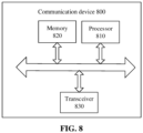
- FIG. 8 is a schematic structural diagram of a communication device 800 according to an embodiment of the present disclosure.
- the communication device may be a terminal or a network device.
- the communication device 800 shown in FIG. 8 includes a processor 810 that may invoke and run computer programs from a memory to perform the method in the embodiments of the present disclosure.
- the communication device 800 may further include a memory 820.
- the processor 810 may invoke and run computer programs from the memory 820 to perform the method in the embodiments of the present disclosure.
- the memory 820 may be a separate device independent of the processor 810 or may be integrated within the processor 810.
- the communication device 800 may further include a transceiver 830 that may be controlled by the processor 810 to communicate with other devices, in particular to send information or data to other devices or receive information or data sent by other devices.
- a transceiver 830 may be controlled by the processor 810 to communicate with other devices, in particular to send information or data to other devices or receive information or data sent by other devices.
- the transceiver 830 may include a transmitter and a receiver.
- the transceiver 830 may further include an antenna, the number of antennas may be one or more.
- the communication device 800 may be specified as the network device of the embodiments of the present disclosure, and the communication device 800 may implement a corresponding flow implemented by the network device in each method of the embodiments of the present disclosure. For brevity, details are not described herein.
- the communication device 800 may be specified as the mobile terminal/terminal of the embodiments of the present disclosure, and the communication device 800 may implement the corresponding flow implemented by the mobile terminal/terminal in the methods of the embodiments of the present disclosure. For brevity, details are not described herein.
- FIG. 9 is a schematic structural diagram of a chip according to an embodiment of the present disclosure.
- the chip 900 shown in FIG. 9 includes a processor 910 that may invoke and run computer programs from a memory to perform the method in the embodiments of the present disclosure.
- the chip 900 may further include a memory 920.
- the processor 910 may invoke and run computer programs from the memory 920 to perform the method in the embodiments of the present disclosure.
- the memory 920 may be a separate device independent of the processor 910 or may be integrated within the processor 910.
- the chip 900 may further include an input interface 930.
- the processor 910 may control the input interface 930 to communicate with other devices or chips, and specifically may acquire information or data sent by the other devices or chips.
- the chip 900 may further include an output interface 940.
- the processor 910 may control the output interface 940 to communicate with other devices or chips, and in particular may output information or data to other devices or chips.
- the chip may be applied to the network device in the embodiments of the present disclosure, and the chip may implement a corresponding flow implemented by the network device in each method in the embodiments of the present disclosure.
- the chip may implement a corresponding flow implemented by the network device in each method in the embodiments of the present disclosure.
- the chip may be applied to the mobile terminal/terminal in the embodiments of the present disclosure, and the chip may implement the corresponding flow implemented by the mobile terminal/terminal in the methods of the embodiments of the present disclosure.
- the chip may implement the corresponding flow implemented by the mobile terminal/terminal in the methods of the embodiments of the present disclosure.
- chip mentioned in the embodiments of the present disclosure may also be referred to as a system level chip, a system chip, a chip-on system or the like.
- FIG. 10 is a schematic block diagram of a communication system 1000 according to an embodiment of the present disclosure. As shown in FIG. 10 , the communication system 1000 includes a terminal 1010 and a network device 1020.
- the terminal 1010 may be configured to implement corresponding functions implemented by the terminal in the methods described above
- the network device 1020 may be configured to implement corresponding functions implemented by the network device in the methods described above.
- the processor of the embodiments of the present disclosure may be an integrated circuit chip having signal processing capability.
- the operations of the above method embodiments may be accomplished by integrated logic circuitry of hardware in a processor or instructions in the form of software.
- the processor may be a general purpose processor, a digital signal processor (DSP), an application specific integrated circuit (ASIC), a field programmable gate array (FPGA) or other programmable logic devices, a discrete gate or transistor logic device, or a discrete hardware component.
- DSP digital signal processor
- ASIC application specific integrated circuit
- FPGA field programmable gate array
- the methods, operations, and logical block diagrams disclosed in the embodiments of the present disclosure may be implemented or performed.
- the general purpose processor may be a microprocessor or the processor may be any conventional processor or the like.
- the operations of the method disclosed in connection with the embodiments of the present disclosure may be directly performed by a hardware decoding processor, or performed by a combination of hardware in the decoding processor and a software module.
- the software module may be located in a storage medium mature in the art, such as a random access memory, a flash memory, a read-only memory, a programmable read-only memory, or an electrically erasable programmable memory, a register, or the like.
- the storage medium is located in the memory, and the processor reads the information in the memory and completes the operations of the methods in combination with the hardware.
- the memory in the embodiments of the present disclosure may be a volatile memory or a non-volatile memory, or may include both volatile and non-volatile memory.
- the non-volatile memory may be a read only memory (ROM), a programmable ROM (PROM), an Erasable PROM (EPROM), an Electrically EPROM (EEPROM) or a flash memory.
- the volatile memory may be a Random Access Memory (RAM) that functions as an external cache.
- RAM Random Rambus RAM
- SRAM Static RAM
- DRAM Dynamic RAM
- SDRAM Synchronous DRAM
- DDR SDRAM Double Data Rate SDRAM
- ESDRAM Enhanced SDRAM
- SLDRAM Synchlink DRAM
- DR RAM Direct Rambus RAM
- the memory described above is exemplary but not limiting, for example, the memory in the embodiments of the present disclosure may also be a static RAM (SRAM), a dynamic RAM (DRAM), a synchronous DRAM (SDRAM), a double data rate SDRAM (DDR SDRAM), an enhanced SDRAM (ESDRAM), a synch link DRAM (SLDRAM), a Direct Rambus RAM (DR RAM), or the like. That is, the memory in the embodiments of the present disclosure is intended to include, but is not limited to, these and any other suitable types of memory.
- SRAM static RAM
- DRAM dynamic RAM
- SDRAM synchronous DRAM
- DDR SDRAM double data rate SDRAM
- ESDRAM enhanced SDRAM
- SLDRAM synch link DRAM
- DR RAM Direct Rambus RAM
- Embodiments of the present disclosure further provide a computer-readable storage medium for storing a computer program.
- the computer-readable storage medium may be applied to the network device in the embodiments of the present disclosure, and the computer program causes a computer to perform the corresponding flow implemented by the network device in the methods in the embodiments of the present disclosure.
- the computer program causes a computer to perform the corresponding flow implemented by the network device in the methods in the embodiments of the present disclosure.
- the computer-readable storage medium may be applied to the mobile terminal/terminal in the embodiments of the present disclosure, and the computer program causes the computer to perform the corresponding flow implemented by the mobile terminal/terminal in the methods of the embodiments of the present disclosure.
- the computer program causes the computer to perform the corresponding flow implemented by the mobile terminal/terminal in the methods of the embodiments of the present disclosure.
- Embodiments of the present disclosure further provide a computer program product including one or more computer program instructions.
- the computer program product may be applied to the network device in the embodiments of the present disclosure, and the computer program instructions cause the computer to perform the corresponding flow implemented by the network device in the methods in the embodiments of the present disclosure.
- the computer program instructions cause the computer to perform the corresponding flow implemented by the network device in the methods in the embodiments of the present disclosure.
- the computer program product may be applied to the mobile terminal/terminal in the embodiments of the present disclosure, and the computer program instructions cause the computer to perform the corresponding flow implemented by the mobile terminal/terminal in the methods of the embodiments of the present disclosure.
- the computer program instructions cause the computer to perform the corresponding flow implemented by the mobile terminal/terminal in the methods of the embodiments of the present disclosure.
- Embodiments of the present disclosure further provide a computer program.
- the computer program may be applied to the network device in the embodiments of the present disclosure.
- the computer program runs on a computer, the computer performs the corresponding flow implemented by the network device in the methods in the embodiments of the present disclosure.
- the computer program runs on a computer, the computer performs the corresponding flow implemented by the network device in the methods in the embodiments of the present disclosure.
- the computer program may be applied to the mobile terminal/terminal in the embodiments of the present disclosure.
- the computer program runs on a computer, the computer performs the corresponding flow implemented by the mobile terminal/terminal in the methods in the embodiments of the present disclosure.
- the computer program runs on a computer, the computer performs the corresponding flow implemented by the mobile terminal/terminal in the methods in the embodiments of the present disclosure.
- the disclosed systems, apparatus, and methods may be implemented in other ways.
- the apparatus embodiments described above are merely illustrative.
- the division of the units is merely a logical function division, and may be implemented in other ways.
- a plurality of units or components may be combined or integrated into another system, or some features may be ignored or not performed.
- the displayed or discussed coupling or direct coupling or communication connection may be implemented via some interfaces, indirect coupling or communication connection among devices or units, and may be in electrical, mechanical or other form.
- the units described as separate units may or may not be physically separate, and the units displayed as units may or may not be physical units, i.e. may be located in one place, or may be distributed over a plurality of network units. Some or all of the units may be selected according to actual needs to achieve the objectives of the solutions of the present embodiment.
- the functions may be stored in a computer-readable storage medium if they are implemented as software functional units and sold or used as stand-alone products. Based on such an understanding, the technical solutions of the present disclosure essentially or part of the contribution to the prior art or part of the technical solutions may be embodied in the form of a software product stored in a storage medium, including several instructions for causing a computer device (which may be a personal computer, a server, a network device, or the like) to perform all or part of the operations of the methods described in the embodiments of the present disclosure.
- the foregoing storage medium includes a USB flash drive, a removable hard disk, a read-only memory (ROM), a random access memory (RAM), a magnetic disk, an optical disc, or any other medium that can store program code.
Landscapes
- Engineering & Computer Science (AREA)
- Signal Processing (AREA)
- Computer Networks & Wireless Communication (AREA)
- Quality & Reliability (AREA)
- Physics & Mathematics (AREA)
- Electromagnetism (AREA)
- Mobile Radio Communication Systems (AREA)
Claims (11)
- Procédé permettant de commander une mesure, caractérisé en ce qu'il comprend :la réception (401), par un terminal, d'une configuration de mesure d'interférence de liaison transversale, CLI, à partir d'un dispositif de réseau, dans lequel la configuration de mesure CLI comprend un ensemble de configurations de ressources de signaux de référence de sondage, SRS, chaque configuration de ressources SRS étant associée à au moins un parmi une identité de cellule ou un indice SRS utilisé pour identifier un SRS correspondant à ladite configuration de ressources SRS, dans lequel dans la configuration de mesure CLI, toutes les ressources SRS correspondent à un objet de mesure, l'objet de mesure comprenant l'ensemble des configurations de ressources SRS ; etla réalisation (402), par le terminal, d'une mesure CLI selon l'ensemble de configurations de ressources SRS de la configuration de mesure CLI afin d'obtenir des résultats de mesure d'un ensemble de SRS, dans lequel la mesure CLI se rapporte au fait que le terminal mesure un SRS d'un autre terminal, dans lequel :lorsqu'un résultat de mesure d'au moins un SRS dans les résultats de mesure de l'ensemble de SRS satisfait à une condition de seuil configurée par le dispositif de réseau, attendre un temps T ;si le résultat de mesure satisfait toujours à la condition de seuil dans le temps T, rapporter, par le terminal, le résultat de mesure au dispositif de réseau, dans lequel une valeur du T est supérieure à 0.
- Procédé selon la revendication 1, dans lequel un contenu rapporté par le terminal au dispositif de réseau comprend l'un des éléments suivants :au moins l'un d'un résultat de mesure d'une puissance reçue de signal de référence SRS, RSRP, d'un résultat de mesure d'une qualité reçue de signal de référence SRS, RSRQ, ou d'un résultat de mesure d'un rapport signal sur interférence plus bruit SRS, SINR, associé à chaque indice SRS ; ouune liste d'indices SRS dont les résultats de mesure satisfont à une condition de seuil configurée par le dispositif de réseau.
- Procédé selon l'une quelconque des revendications 1 ou 2, dans lequel un contenu rapporté par le terminal au dispositif de réseau comprend en outre un identificateur de mesure associé à la configuration de mesure du SRS.
- Procédé selon l'une quelconque des revendications 1 à 3, dans lequel le résultat de mesure satisfaisant à une condition de seuil configurée par le dispositif de réseau comprend l'un des éléments suivants :le résultat de mesure est supérieur ou égal à un premier seuil configuré par le dispositif de réseau ; oule résultat de mesure est inférieur ou égal à un premier seuil configuré par le dispositif de réseau.
- Appareil permettant de commander une mesure, caractérisé en ce qu'il comprend :une unité de réception (701), configurée pour recevoir une configuration de mesure d'interférence de liaison transversale, CLI, à partir d'un dispositif de réseau, dans lequel la configuration de mesure CLI comprend un ensemble de configurations de ressources de signaux de référence de sondage, SRS, chaque configuration de ressources SRS étant associée à au moins un parmi une identité de cellule ou un indice SRS utilisé pour identifier un SRS correspondant à ladite chaque configuration de ressources SRS, dans lequel dans la configuration de mesure CLI, toutes les ressources SRS correspondent à un objet de mesure, l'objet de mesure comprenant l'ensemble de configurations de ressources SRS ; etune unité de mesure (702), configurée pour réaliser une mesure CLI selon l'ensemble de configurations de ressources SRS de la configuration de mesure CLI afin d'obtenir des résultats de mesure d'un ensemble de SRS, dans lequel la mesure CLI se rapporte au fait que le terminal mesure un SRS d'un autre terminal, dans lequel l'appareil comprend en outre :une unité d'établissement de rapport (703), configurée pour : lorsqu'un résultat de mesure d'au moins un SRS dans les résultats de mesure de l'ensemble de SRS satisfait à une condition de seuil configurée par le dispositif de réseau, attendre un temps T ; etsi le résultat de mesure satisfait toujours à la condition de seuil dans le temps T, rapporter le résultat de mesure au dispositif de réseau, dans lequel une valeur du T est supérieure à 0.
- Appareil selon la revendication 5, dans lequel un contenu rapporté par l'unité d'établissement de rapport (703) au dispositif de réseau comprend l'un des éléments suivants :au moins l'un d'un résultat de mesure d'une puissance reçue de signal de référence SRS, RSRP, d'un résultat de mesure d'une qualité reçue de signal de référence SRS, RSRQ, ou d'un résultat de mesure d'un rapport signal sur interférence plus bruit SRS, SINR, associé à chaque indice SRS ; ouune liste d'indices SRS dont les résultats de mesure satisfont à une condition de seuil configurée par le dispositif de réseau.
- Appareil selon l'une quelconque des revendications 5 et 6, dans lequel un contenu rapporté par l'unité d'établissement de rapport (703) au dispositif de réseau comprend en outre un identificateur de mesure associé à la configuration de mesure du SRS.
- Appareil selon l'une quelconque des revendications 5 à 7, dans lequel le résultat de mesure satisfaisant à une condition de seuil configurée par le dispositif de réseau comprend l'un des éléments suivants :le résultat de mesure est supérieur ou égal à un premier seuil configuré par le dispositif de réseau ; oule résultat de mesure est inférieur ou égal à un premier seuil configuré par le dispositif de réseau.
- Terminal, comprenant :un processeur ; etune mémoire destinée à mémoriser un programme informatique,dans lequel le processeur est configuré pour invoquer et exécuter le programme informatique mémorisé dans la mémoire pour réaliser le procédé selon l'une quelconque des revendications 1 à 4.
- Puce, comprenant un processeur configuré pour invoquer et exécuter un programme informatique à partir d'une mémoire pour amener un dispositif sur lequel est montée la puce à réaliser le procédé selon l'une quelconque des revendications 1 à 4.
- Support d'enregistrement lisible par ordinateur dans lequel est mémorisé un programme informatique qui, lorsqu'il est exécuté par un ordinateur, amène l'ordinateur à réaliser le procédé selon l'une quelconque des revendications 1 à 4.
Applications Claiming Priority (1)
| Application Number | Priority Date | Filing Date | Title |
|---|---|---|---|
| PCT/CN2019/090438 WO2020243972A1 (fr) | 2019-06-06 | 2019-06-06 | Procédé et appareil de commande de mesure, terminal et dispositif de réseau |
Publications (3)
| Publication Number | Publication Date |
|---|---|
| EP3930367A1 EP3930367A1 (fr) | 2021-12-29 |
| EP3930367A4 EP3930367A4 (fr) | 2022-03-09 |
| EP3930367B1 true EP3930367B1 (fr) | 2023-10-04 |
Family
ID=73652399
Family Applications (1)
| Application Number | Title | Priority Date | Filing Date |
|---|---|---|---|
| EP19931676.1A Active EP3930367B1 (fr) | 2019-06-06 | 2019-06-06 | Procédé et appareil de commande de mesure, terminal et dispositif de réseau |
Country Status (6)
| Country | Link |
|---|---|
| US (1) | US11825322B2 (fr) |
| EP (1) | EP3930367B1 (fr) |
| JP (1) | JP7319394B2 (fr) |
| KR (1) | KR102926169B1 (fr) |
| CN (2) | CN112740740A (fr) |
| WO (1) | WO2020243972A1 (fr) |
Families Citing this family (8)
| Publication number | Priority date | Publication date | Assignee | Title |
|---|---|---|---|---|
| US11792670B2 (en) * | 2019-11-08 | 2023-10-17 | Samsung Electronics Co., Ltd. | Method and apparatus for performing dynamic cross-link interference measurement and reporting in next-generation mobile communication system |
| KR102922007B1 (ko) * | 2019-11-19 | 2026-02-02 | 삼성전자주식회사 | 무선 통신 시스템에서 간섭 신호 측정 방법 및 장치 |
| CN115336315B (zh) | 2020-04-10 | 2024-05-17 | 高通股份有限公司 | 交叉链路干扰测量配置 |
| EP4147476A4 (fr) * | 2020-05-09 | 2024-02-21 | Qualcomm Incorporated | Signal de référence pour mesures de brouillage inter-liaisons |
| CN115474218B (zh) * | 2021-06-11 | 2025-09-02 | 华为技术有限公司 | 一种cli的测量方法及通信装置 |
| CN116938414A (zh) * | 2022-04-07 | 2023-10-24 | 华为技术有限公司 | 一种通信方法、装置及系统 |
| US12587888B2 (en) * | 2022-10-31 | 2026-03-24 | Qualcomm Incorporated | Joint activation of cross-link interference measurement and reporting |
| CN119893723A (zh) * | 2023-10-24 | 2025-04-25 | 北京三星通信技术研究有限公司 | 无线通信系统中的用户设备、节点及其执行的方法 |
Family Cites Families (9)
| Publication number | Priority date | Publication date | Assignee | Title |
|---|---|---|---|---|
| EP2920934B1 (fr) | 2012-11-14 | 2020-12-23 | Telefonaktiebolaget LM Ericsson (publ) | Procédé de transmission de signal pilote, point de transmission et de réception associé, procédé de réception de signal pilote, et équipement d'utilisateur associé |
| US11202218B2 (en) * | 2017-01-09 | 2021-12-14 | Lg Electronics Inc. | Method for reporting measurement data, and terminal therefor |
| CN108289311B (zh) * | 2017-01-09 | 2022-10-14 | 中兴通讯股份有限公司 | 干扰测量方法及装置和定时偏差测量方法 |
| CN110447272B (zh) * | 2017-03-22 | 2023-01-24 | Idac控股公司 | Nr动态tdd系统内的动态干扰管理 |
| US20180367346A1 (en) * | 2017-06-16 | 2018-12-20 | Mediatek Inc. | Cross-Link Interference Measurement In Mobile Communications |
| GB2567287B (en) * | 2017-08-07 | 2020-12-30 | Samsung Electronics Co Ltd | Network control |
| EP3665928B1 (fr) * | 2017-08-11 | 2023-11-15 | Telefonaktiebolaget LM Ericsson (publ) | Mesure et rapport destinés à une gestion de brouillage entre liaisons en fonction de signaux de référence |
| KR20210004447A (ko) * | 2019-07-04 | 2021-01-13 | 삼성전자주식회사 | 차세대 이동 통신 시스템에서 교차 링크 간섭에 대한 측정과 보고 방법 및 장치 |
| KR102879247B1 (ko) * | 2021-01-26 | 2025-10-31 | 삼성전자주식회사 | 무선 통신 시스템에서 세션을 설정하는 방법 및 장치 |
-
2019
- 2019-06-06 KR KR1020217041855A patent/KR102926169B1/ko active Active
- 2019-06-06 CN CN201980062509.XA patent/CN112740740A/zh active Pending
- 2019-06-06 WO PCT/CN2019/090438 patent/WO2020243972A1/fr not_active Ceased
- 2019-06-06 CN CN202110577075.6A patent/CN113329426A/zh active Pending
- 2019-06-06 JP JP2021571702A patent/JP7319394B2/ja active Active
- 2019-06-06 EP EP19931676.1A patent/EP3930367B1/fr active Active
-
2021
- 2021-09-10 US US17/471,360 patent/US11825322B2/en active Active
Also Published As
| Publication number | Publication date |
|---|---|
| WO2020243972A1 (fr) | 2020-12-10 |
| JP2022538382A (ja) | 2022-09-02 |
| JP7319394B2 (ja) | 2023-08-01 |
| KR20220017938A (ko) | 2022-02-14 |
| US20210409986A1 (en) | 2021-12-30 |
| US11825322B2 (en) | 2023-11-21 |
| EP3930367A4 (fr) | 2022-03-09 |
| CN112740740A (zh) | 2021-04-30 |
| CN113329426A (zh) | 2021-08-31 |
| EP3930367A1 (fr) | 2021-12-29 |
| KR102926169B1 (ko) | 2026-02-10 |
Similar Documents
| Publication | Publication Date | Title |
|---|---|---|
| US11825322B2 (en) | Measurement control method, terminal, and non-transitory computer-readable storage medium | |
| EP3739922B1 (fr) | Procédé de rapport de capacité d'équipement utilisateur et procédé de planification de ressource, équipement utilisateur et dispositif de réseau | |
| US12213013B2 (en) | Cell configuration method and apparatus, terminal device, and network device | |
| US11317464B2 (en) | Cell state management method and apparatus, terminal device, and network device | |
| US12213149B2 (en) | Method for configuring PDCCH detection and related device | |
| US12267731B2 (en) | Method and device for resource coordination | |
| US20210250866A1 (en) | Method and apparatus for reducing terminal power consumption, and terminal | |
| WO2021056460A1 (fr) | Procédé et appareil de gestion de mesure, et dispositif de communication | |
| US12149460B2 (en) | Wireless communication method, network device, and terminal device | |
| WO2021114206A1 (fr) | Procédé et appareil de mesure de cli, dispositif terminal et dispositif de réseau | |
| US12302143B2 (en) | Measurement method, terminal device and non-transitory computer-readable storage medium for a master cell group and a secondary cell group | |
| WO2020154871A1 (fr) | Procédé de commande de mesure, dispositif terminal, et dispositif de réseau | |
| US11985026B2 (en) | Processing method and device for link recovery process, and terminal |
Legal Events
| Date | Code | Title | Description |
|---|---|---|---|
| STAA | Information on the status of an ep patent application or granted ep patent |
Free format text: STATUS: THE INTERNATIONAL PUBLICATION HAS BEEN MADE |
|
| PUAI | Public reference made under article 153(3) epc to a published international application that has entered the european phase |
Free format text: ORIGINAL CODE: 0009012 |
|
| STAA | Information on the status of an ep patent application or granted ep patent |
Free format text: STATUS: REQUEST FOR EXAMINATION WAS MADE |
|
| 17P | Request for examination filed |
Effective date: 20210921 |
|
| AK | Designated contracting states |
Kind code of ref document: A1 Designated state(s): AL AT BE BG CH CY CZ DE DK EE ES FI FR GB GR HR HU IE IS IT LI LT LU LV MC MK MT NL NO PL PT RO RS SE SI SK SM TR |
|
| A4 | Supplementary search report drawn up and despatched |
Effective date: 20220204 |
|
| RIC1 | Information provided on ipc code assigned before grant |
Ipc: H04L 43/16 20220101ALN20220131BHEP Ipc: H04B 17/345 20150101ALN20220131BHEP Ipc: H04B 17/327 20150101ALN20220131BHEP Ipc: H04W 24/10 20090101ALI20220131BHEP Ipc: H04W 24/00 20090101ALI20220131BHEP Ipc: H04B 17/309 20150101AFI20220131BHEP |
|
| STAA | Information on the status of an ep patent application or granted ep patent |
Free format text: STATUS: EXAMINATION IS IN PROGRESS |
|
| 17Q | First examination report despatched |
Effective date: 20220801 |
|
| DAV | Request for validation of the european patent (deleted) | ||
| DAX | Request for extension of the european patent (deleted) | ||
| REG | Reference to a national code |
Ref country code: DE Free format text: PREVIOUS MAIN CLASS: H04W0024000000 Ref country code: DE Ref legal event code: R079 Ref document number: 602019038949 Country of ref document: DE Free format text: PREVIOUS MAIN CLASS: H04W0024000000 Ipc: H04B0017309000 |
|
| GRAP | Despatch of communication of intention to grant a patent |
Free format text: ORIGINAL CODE: EPIDOSNIGR1 |
|
| STAA | Information on the status of an ep patent application or granted ep patent |
Free format text: STATUS: GRANT OF PATENT IS INTENDED |
|
| RIC1 | Information provided on ipc code assigned before grant |
Ipc: H04L 43/16 20220101ALN20230630BHEP Ipc: H04B 17/345 20150101ALN20230630BHEP Ipc: H04B 17/327 20150101ALN20230630BHEP Ipc: H04W 24/10 20090101ALI20230630BHEP Ipc: H04W 24/00 20090101ALI20230630BHEP Ipc: H04B 17/309 20150101AFI20230630BHEP |
|
| INTG | Intention to grant announced |
Effective date: 20230719 |
|
| GRAS | Grant fee paid |
Free format text: ORIGINAL CODE: EPIDOSNIGR3 |
|
| GRAA | (expected) grant |
Free format text: ORIGINAL CODE: 0009210 |
|
| STAA | Information on the status of an ep patent application or granted ep patent |
Free format text: STATUS: THE PATENT HAS BEEN GRANTED |
|
| AK | Designated contracting states |
Kind code of ref document: B1 Designated state(s): AL AT BE BG CH CY CZ DE DK EE ES FI FR GB GR HR HU IE IS IT LI LT LU LV MC MK MT NL NO PL PT RO RS SE SI SK SM TR |
|
| REG | Reference to a national code |
Ref country code: GB Ref legal event code: FG4D |
|
| REG | Reference to a national code |
Ref country code: CH Ref legal event code: EP |
|
| REG | Reference to a national code |
Ref country code: IE Ref legal event code: FG4D |
|
| REG | Reference to a national code |
Ref country code: DE Ref legal event code: R096 Ref document number: 602019038949 Country of ref document: DE |
|
| P01 | Opt-out of the competence of the unified patent court (upc) registered |
Effective date: 20231016 |
|
| REG | Reference to a national code |
Ref country code: LT Ref legal event code: MG9D |
|
| REG | Reference to a national code |
Ref country code: NL Ref legal event code: MP Effective date: 20231004 |
|
| REG | Reference to a national code |
Ref country code: AT Ref legal event code: MK05 Ref document number: 1618856 Country of ref document: AT Kind code of ref document: T Effective date: 20231004 |
|
| PG25 | Lapsed in a contracting state [announced via postgrant information from national office to epo] |
Ref country code: NL Free format text: LAPSE BECAUSE OF FAILURE TO SUBMIT A TRANSLATION OF THE DESCRIPTION OR TO PAY THE FEE WITHIN THE PRESCRIBED TIME-LIMIT Effective date: 20231004 |
|
| PG25 | Lapsed in a contracting state [announced via postgrant information from national office to epo] |
Ref country code: GR Free format text: LAPSE BECAUSE OF FAILURE TO SUBMIT A TRANSLATION OF THE DESCRIPTION OR TO PAY THE FEE WITHIN THE PRESCRIBED TIME-LIMIT Effective date: 20240105 |
|
| PG25 | Lapsed in a contracting state [announced via postgrant information from national office to epo] |
Ref country code: IS Free format text: LAPSE BECAUSE OF FAILURE TO SUBMIT A TRANSLATION OF THE DESCRIPTION OR TO PAY THE FEE WITHIN THE PRESCRIBED TIME-LIMIT Effective date: 20240204 |
|
| PG25 | Lapsed in a contracting state [announced via postgrant information from national office to epo] |
Ref country code: LT Free format text: LAPSE BECAUSE OF FAILURE TO SUBMIT A TRANSLATION OF THE DESCRIPTION OR TO PAY THE FEE WITHIN THE PRESCRIBED TIME-LIMIT Effective date: 20231004 |
|
| PG25 | Lapsed in a contracting state [announced via postgrant information from national office to epo] |
Ref country code: AT Free format text: LAPSE BECAUSE OF FAILURE TO SUBMIT A TRANSLATION OF THE DESCRIPTION OR TO PAY THE FEE WITHIN THE PRESCRIBED TIME-LIMIT Effective date: 20231004 |
|
| PG25 | Lapsed in a contracting state [announced via postgrant information from national office to epo] |
Ref country code: ES Free format text: LAPSE BECAUSE OF FAILURE TO SUBMIT A TRANSLATION OF THE DESCRIPTION OR TO PAY THE FEE WITHIN THE PRESCRIBED TIME-LIMIT Effective date: 20231004 |
|
| PG25 | Lapsed in a contracting state [announced via postgrant information from national office to epo] |
Ref country code: LT Free format text: LAPSE BECAUSE OF FAILURE TO SUBMIT A TRANSLATION OF THE DESCRIPTION OR TO PAY THE FEE WITHIN THE PRESCRIBED TIME-LIMIT Effective date: 20231004 Ref country code: IS Free format text: LAPSE BECAUSE OF FAILURE TO SUBMIT A TRANSLATION OF THE DESCRIPTION OR TO PAY THE FEE WITHIN THE PRESCRIBED TIME-LIMIT Effective date: 20240204 Ref country code: GR Free format text: LAPSE BECAUSE OF FAILURE TO SUBMIT A TRANSLATION OF THE DESCRIPTION OR TO PAY THE FEE WITHIN THE PRESCRIBED TIME-LIMIT Effective date: 20240105 Ref country code: ES Free format text: LAPSE BECAUSE OF FAILURE TO SUBMIT A TRANSLATION OF THE DESCRIPTION OR TO PAY THE FEE WITHIN THE PRESCRIBED TIME-LIMIT Effective date: 20231004 Ref country code: BG Free format text: LAPSE BECAUSE OF FAILURE TO SUBMIT A TRANSLATION OF THE DESCRIPTION OR TO PAY THE FEE WITHIN THE PRESCRIBED TIME-LIMIT Effective date: 20240104 Ref country code: AT Free format text: LAPSE BECAUSE OF FAILURE TO SUBMIT A TRANSLATION OF THE DESCRIPTION OR TO PAY THE FEE WITHIN THE PRESCRIBED TIME-LIMIT Effective date: 20231004 Ref country code: PT Free format text: LAPSE BECAUSE OF FAILURE TO SUBMIT A TRANSLATION OF THE DESCRIPTION OR TO PAY THE FEE WITHIN THE PRESCRIBED TIME-LIMIT Effective date: 20240205 |
|
| PG25 | Lapsed in a contracting state [announced via postgrant information from national office to epo] |
Ref country code: SE Free format text: LAPSE BECAUSE OF FAILURE TO SUBMIT A TRANSLATION OF THE DESCRIPTION OR TO PAY THE FEE WITHIN THE PRESCRIBED TIME-LIMIT Effective date: 20231004 Ref country code: RS Free format text: LAPSE BECAUSE OF FAILURE TO SUBMIT A TRANSLATION OF THE DESCRIPTION OR TO PAY THE FEE WITHIN THE PRESCRIBED TIME-LIMIT Effective date: 20231004 Ref country code: PL Free format text: LAPSE BECAUSE OF FAILURE TO SUBMIT A TRANSLATION OF THE DESCRIPTION OR TO PAY THE FEE WITHIN THE PRESCRIBED TIME-LIMIT Effective date: 20231004 Ref country code: NO Free format text: LAPSE BECAUSE OF FAILURE TO SUBMIT A TRANSLATION OF THE DESCRIPTION OR TO PAY THE FEE WITHIN THE PRESCRIBED TIME-LIMIT Effective date: 20240104 Ref country code: LV Free format text: LAPSE BECAUSE OF FAILURE TO SUBMIT A TRANSLATION OF THE DESCRIPTION OR TO PAY THE FEE WITHIN THE PRESCRIBED TIME-LIMIT Effective date: 20231004 Ref country code: HR Free format text: LAPSE BECAUSE OF FAILURE TO SUBMIT A TRANSLATION OF THE DESCRIPTION OR TO PAY THE FEE WITHIN THE PRESCRIBED TIME-LIMIT Effective date: 20231004 |
|
| REG | Reference to a national code |
Ref country code: DE Ref legal event code: R097 Ref document number: 602019038949 Country of ref document: DE |
|
| PG25 | Lapsed in a contracting state [announced via postgrant information from national office to epo] |
Ref country code: DK Free format text: LAPSE BECAUSE OF FAILURE TO SUBMIT A TRANSLATION OF THE DESCRIPTION OR TO PAY THE FEE WITHIN THE PRESCRIBED TIME-LIMIT Effective date: 20231004 |
|
| PG25 | Lapsed in a contracting state [announced via postgrant information from national office to epo] |
Ref country code: CZ Free format text: LAPSE BECAUSE OF FAILURE TO SUBMIT A TRANSLATION OF THE DESCRIPTION OR TO PAY THE FEE WITHIN THE PRESCRIBED TIME-LIMIT Effective date: 20231004 |
|
| PG25 | Lapsed in a contracting state [announced via postgrant information from national office to epo] |
Ref country code: SK Free format text: LAPSE BECAUSE OF FAILURE TO SUBMIT A TRANSLATION OF THE DESCRIPTION OR TO PAY THE FEE WITHIN THE PRESCRIBED TIME-LIMIT Effective date: 20231004 |
|
| PG25 | Lapsed in a contracting state [announced via postgrant information from national office to epo] |
Ref country code: SM Free format text: LAPSE BECAUSE OF FAILURE TO SUBMIT A TRANSLATION OF THE DESCRIPTION OR TO PAY THE FEE WITHIN THE PRESCRIBED TIME-LIMIT Effective date: 20231004 Ref country code: SK Free format text: LAPSE BECAUSE OF FAILURE TO SUBMIT A TRANSLATION OF THE DESCRIPTION OR TO PAY THE FEE WITHIN THE PRESCRIBED TIME-LIMIT Effective date: 20231004 Ref country code: RO Free format text: LAPSE BECAUSE OF FAILURE TO SUBMIT A TRANSLATION OF THE DESCRIPTION OR TO PAY THE FEE WITHIN THE PRESCRIBED TIME-LIMIT Effective date: 20231004 Ref country code: IT Free format text: LAPSE BECAUSE OF FAILURE TO SUBMIT A TRANSLATION OF THE DESCRIPTION OR TO PAY THE FEE WITHIN THE PRESCRIBED TIME-LIMIT Effective date: 20231004 Ref country code: EE Free format text: LAPSE BECAUSE OF FAILURE TO SUBMIT A TRANSLATION OF THE DESCRIPTION OR TO PAY THE FEE WITHIN THE PRESCRIBED TIME-LIMIT Effective date: 20231004 Ref country code: DK Free format text: LAPSE BECAUSE OF FAILURE TO SUBMIT A TRANSLATION OF THE DESCRIPTION OR TO PAY THE FEE WITHIN THE PRESCRIBED TIME-LIMIT Effective date: 20231004 Ref country code: CZ Free format text: LAPSE BECAUSE OF FAILURE TO SUBMIT A TRANSLATION OF THE DESCRIPTION OR TO PAY THE FEE WITHIN THE PRESCRIBED TIME-LIMIT Effective date: 20231004 |
|
| PLBE | No opposition filed within time limit |
Free format text: ORIGINAL CODE: 0009261 |
|
| STAA | Information on the status of an ep patent application or granted ep patent |
Free format text: STATUS: NO OPPOSITION FILED WITHIN TIME LIMIT |
|
| 26N | No opposition filed |
Effective date: 20240705 |
|
| PG25 | Lapsed in a contracting state [announced via postgrant information from national office to epo] |
Ref country code: SI Free format text: LAPSE BECAUSE OF FAILURE TO SUBMIT A TRANSLATION OF THE DESCRIPTION OR TO PAY THE FEE WITHIN THE PRESCRIBED TIME-LIMIT Effective date: 20231004 |
|
| PG25 | Lapsed in a contracting state [announced via postgrant information from national office to epo] |
Ref country code: SI Free format text: LAPSE BECAUSE OF FAILURE TO SUBMIT A TRANSLATION OF THE DESCRIPTION OR TO PAY THE FEE WITHIN THE PRESCRIBED TIME-LIMIT Effective date: 20231004 |
|
| PG25 | Lapsed in a contracting state [announced via postgrant information from national office to epo] |
Ref country code: MC Free format text: LAPSE BECAUSE OF FAILURE TO SUBMIT A TRANSLATION OF THE DESCRIPTION OR TO PAY THE FEE WITHIN THE PRESCRIBED TIME-LIMIT Effective date: 20231004 |
|
| REG | Reference to a national code |
Ref country code: CH Ref legal event code: PL |
|
| PG25 | Lapsed in a contracting state [announced via postgrant information from national office to epo] |
Ref country code: LU Free format text: LAPSE BECAUSE OF NON-PAYMENT OF DUE FEES Effective date: 20240606 |
|
| PG25 | Lapsed in a contracting state [announced via postgrant information from national office to epo] |
Ref country code: IE Free format text: LAPSE BECAUSE OF NON-PAYMENT OF DUE FEES Effective date: 20240606 |
|
| PG25 | Lapsed in a contracting state [announced via postgrant information from national office to epo] |
Ref country code: BE Free format text: LAPSE BECAUSE OF NON-PAYMENT OF DUE FEES Effective date: 20240630 Ref country code: CH Free format text: LAPSE BECAUSE OF NON-PAYMENT OF DUE FEES Effective date: 20240630 |
|
| REG | Reference to a national code |
Ref country code: BE Ref legal event code: MM Effective date: 20240630 |
|
| PGFP | Annual fee paid to national office [announced via postgrant information from national office to epo] |
Ref country code: DE Payment date: 20250625 Year of fee payment: 7 |
|
| PGFP | Annual fee paid to national office [announced via postgrant information from national office to epo] |
Ref country code: GB Payment date: 20250620 Year of fee payment: 7 |
|
| PGFP | Annual fee paid to national office [announced via postgrant information from national office to epo] |
Ref country code: FR Payment date: 20250620 Year of fee payment: 7 |
|
| PG25 | Lapsed in a contracting state [announced via postgrant information from national office to epo] |
Ref country code: FI Free format text: LAPSE BECAUSE OF FAILURE TO SUBMIT A TRANSLATION OF THE DESCRIPTION OR TO PAY THE FEE WITHIN THE PRESCRIBED TIME-LIMIT Effective date: 20231004 |
|
| PG25 | Lapsed in a contracting state [announced via postgrant information from national office to epo] |
Ref country code: CY Free format text: LAPSE BECAUSE OF FAILURE TO SUBMIT A TRANSLATION OF THE DESCRIPTION OR TO PAY THE FEE WITHIN THE PRESCRIBED TIME-LIMIT; INVALID AB INITIO Effective date: 20190606 |
|
| PG25 | Lapsed in a contracting state [announced via postgrant information from national office to epo] |
Ref country code: HU Free format text: LAPSE BECAUSE OF FAILURE TO SUBMIT A TRANSLATION OF THE DESCRIPTION OR TO PAY THE FEE WITHIN THE PRESCRIBED TIME-LIMIT; INVALID AB INITIO Effective date: 20190606 |