EP3930628B1 - Doppelte herzklappenverankerung - Google Patents
Doppelte herzklappenverankerung Download PDFInfo
- Publication number
- EP3930628B1 EP3930628B1 EP20709898.9A EP20709898A EP3930628B1 EP 3930628 B1 EP3930628 B1 EP 3930628B1 EP 20709898 A EP20709898 A EP 20709898A EP 3930628 B1 EP3930628 B1 EP 3930628B1
- Authority
- EP
- European Patent Office
- Prior art keywords
- connector
- valve replacement
- mitral valve
- anchor
- replacement
- Prior art date
- Legal status (The legal status is an assumption and is not a legal conclusion. Google has not performed a legal analysis and makes no representation as to the accuracy of the status listed.)
- Active
Links
Images




Classifications
-
- A—HUMAN NECESSITIES
- A61—MEDICAL OR VETERINARY SCIENCE; HYGIENE
- A61F—FILTERS IMPLANTABLE INTO BLOOD VESSELS; PROSTHESES; DEVICES PROVIDING PATENCY TO, OR PREVENTING COLLAPSING OF, TUBULAR STRUCTURES OF THE BODY, e.g. STENTS; ORTHOPAEDIC, NURSING OR CONTRACEPTIVE DEVICES; FOMENTATION; TREATMENT OR PROTECTION OF EYES OR EARS; BANDAGES, DRESSINGS OR ABSORBENT PADS; FIRST-AID KITS
- A61F2/00—Filters implantable into blood vessels; Prostheses, i.e. artificial substitutes or replacements for parts of the body; Appliances for connecting them with the body; Devices providing patency to, or preventing collapsing of, tubular structures of the body, e.g. stents
- A61F2/02—Prostheses implantable into the body
- A61F2/24—Heart valves ; Vascular valves, e.g. venous valves; Heart implants, e.g. passive devices for improving the function of the native valve or the heart muscle; Transmyocardial revascularisation [TMR] devices; Valves implantable in the body
- A61F2/2412—Heart valves ; Vascular valves, e.g. venous valves; Heart implants, e.g. passive devices for improving the function of the native valve or the heart muscle; Transmyocardial revascularisation [TMR] devices; Valves implantable in the body with soft flexible valve members, e.g. tissue valves shaped like natural valves
- A61F2/2418—Scaffolds therefor, e.g. support stents
-
- A—HUMAN NECESSITIES
- A61—MEDICAL OR VETERINARY SCIENCE; HYGIENE
- A61F—FILTERS IMPLANTABLE INTO BLOOD VESSELS; PROSTHESES; DEVICES PROVIDING PATENCY TO, OR PREVENTING COLLAPSING OF, TUBULAR STRUCTURES OF THE BODY, e.g. STENTS; ORTHOPAEDIC, NURSING OR CONTRACEPTIVE DEVICES; FOMENTATION; TREATMENT OR PROTECTION OF EYES OR EARS; BANDAGES, DRESSINGS OR ABSORBENT PADS; FIRST-AID KITS
- A61F2/00—Filters implantable into blood vessels; Prostheses, i.e. artificial substitutes or replacements for parts of the body; Appliances for connecting them with the body; Devices providing patency to, or preventing collapsing of, tubular structures of the body, e.g. stents
- A61F2/02—Prostheses implantable into the body
- A61F2/24—Heart valves ; Vascular valves, e.g. venous valves; Heart implants, e.g. passive devices for improving the function of the native valve or the heart muscle; Transmyocardial revascularisation [TMR] devices; Valves implantable in the body
-
- A—HUMAN NECESSITIES
- A61—MEDICAL OR VETERINARY SCIENCE; HYGIENE
- A61F—FILTERS IMPLANTABLE INTO BLOOD VESSELS; PROSTHESES; DEVICES PROVIDING PATENCY TO, OR PREVENTING COLLAPSING OF, TUBULAR STRUCTURES OF THE BODY, e.g. STENTS; ORTHOPAEDIC, NURSING OR CONTRACEPTIVE DEVICES; FOMENTATION; TREATMENT OR PROTECTION OF EYES OR EARS; BANDAGES, DRESSINGS OR ABSORBENT PADS; FIRST-AID KITS
- A61F2220/00—Fixations or connections for prostheses classified in groups A61F2/00 - A61F2/26 or A61F2/82 or A61F9/00 or A61F11/00 or subgroups thereof
- A61F2220/0008—Fixation appliances for connecting prostheses to the body
-
- A—HUMAN NECESSITIES
- A61—MEDICAL OR VETERINARY SCIENCE; HYGIENE
- A61F—FILTERS IMPLANTABLE INTO BLOOD VESSELS; PROSTHESES; DEVICES PROVIDING PATENCY TO, OR PREVENTING COLLAPSING OF, TUBULAR STRUCTURES OF THE BODY, e.g. STENTS; ORTHOPAEDIC, NURSING OR CONTRACEPTIVE DEVICES; FOMENTATION; TREATMENT OR PROTECTION OF EYES OR EARS; BANDAGES, DRESSINGS OR ABSORBENT PADS; FIRST-AID KITS
- A61F2220/00—Fixations or connections for prostheses classified in groups A61F2/00 - A61F2/26 or A61F2/82 or A61F9/00 or A61F11/00 or subgroups thereof
- A61F2220/0025—Connections or couplings between prosthetic parts, e.g. between modular parts; Connecting elements
- A61F2220/0075—Connections or couplings between prosthetic parts, e.g. between modular parts; Connecting elements sutured, ligatured or stitched, retained or tied with a rope, string, thread, wire or cable
-
- A—HUMAN NECESSITIES
- A61—MEDICAL OR VETERINARY SCIENCE; HYGIENE
- A61F—FILTERS IMPLANTABLE INTO BLOOD VESSELS; PROSTHESES; DEVICES PROVIDING PATENCY TO, OR PREVENTING COLLAPSING OF, TUBULAR STRUCTURES OF THE BODY, e.g. STENTS; ORTHOPAEDIC, NURSING OR CONTRACEPTIVE DEVICES; FOMENTATION; TREATMENT OR PROTECTION OF EYES OR EARS; BANDAGES, DRESSINGS OR ABSORBENT PADS; FIRST-AID KITS
- A61F2230/00—Geometry of prostheses classified in groups A61F2/00 - A61F2/26 or A61F2/82 or A61F9/00 or A61F11/00 or subgroups thereof
- A61F2230/0002—Two-dimensional shapes, e.g. cross-sections
- A61F2230/0028—Shapes in the form of latin or greek characters
- A61F2230/0054—V-shaped
-
- A—HUMAN NECESSITIES
- A61—MEDICAL OR VETERINARY SCIENCE; HYGIENE
- A61F—FILTERS IMPLANTABLE INTO BLOOD VESSELS; PROSTHESES; DEVICES PROVIDING PATENCY TO, OR PREVENTING COLLAPSING OF, TUBULAR STRUCTURES OF THE BODY, e.g. STENTS; ORTHOPAEDIC, NURSING OR CONTRACEPTIVE DEVICES; FOMENTATION; TREATMENT OR PROTECTION OF EYES OR EARS; BANDAGES, DRESSINGS OR ABSORBENT PADS; FIRST-AID KITS
- A61F2250/00—Special features of prostheses classified in groups A61F2/00 - A61F2/26 or A61F2/82 or A61F9/00 or A61F11/00 or subgroups thereof
- A61F2250/0004—Special features of prostheses classified in groups A61F2/00 - A61F2/26 or A61F2/82 or A61F9/00 or A61F11/00 or subgroups thereof adjustable
- A61F2250/0007—Special features of prostheses classified in groups A61F2/00 - A61F2/26 or A61F2/82 or A61F9/00 or A61F11/00 or subgroups thereof adjustable for adjusting length
-
- A—HUMAN NECESSITIES
- A61—MEDICAL OR VETERINARY SCIENCE; HYGIENE
- A61F—FILTERS IMPLANTABLE INTO BLOOD VESSELS; PROSTHESES; DEVICES PROVIDING PATENCY TO, OR PREVENTING COLLAPSING OF, TUBULAR STRUCTURES OF THE BODY, e.g. STENTS; ORTHOPAEDIC, NURSING OR CONTRACEPTIVE DEVICES; FOMENTATION; TREATMENT OR PROTECTION OF EYES OR EARS; BANDAGES, DRESSINGS OR ABSORBENT PADS; FIRST-AID KITS
- A61F2250/00—Special features of prostheses classified in groups A61F2/00 - A61F2/26 or A61F2/82 or A61F9/00 or A61F11/00 or subgroups thereof
- A61F2250/0058—Additional features; Implant or prostheses properties not otherwise provided for
- A61F2250/006—Additional features; Implant or prostheses properties not otherwise provided for modular
Definitions
- the present disclosure generally relates to the field of medical implant devices.
- Implantation of heart valve devices can be performed to address various heart valve abnormalities. Implantation of both a tricuspid valve device and a mitral valve device can be advantageous for patients suffering from dysfunction in both valves.
- EP 3 184081 A1 discloses a prosthetic mitral valve coaptation enhancement device comprising a main body consisting of a stent frame and a valve element attached thereto, wherein the main body has a sealing section and a valve-bearing section, the valve-bearing section carrying the valve element.
- the shape of the sealing section of the main body, in the compressed state, has a form that is adapted to the coaptation zone of the native mitral valve during systole, and the radial rigidity of the sealing section of the stent frame is lower than the radial rigidity of the valve-bearing section.
- the prosthetic mitral valve coaptation enhancement device further comprises at least one anchoring element, which anchoring element is coupled to the main body and is capable to anchor the main body within the native mitral valve region of a heart.
- Described herein are one or more methods not belonging to the claimed invention and/or devices to anchor both a tricuspid valve device and a mitral valve device to the septum.
- the present disclosure relates to a double heart valve anchoring system comprising a first anchor which comprises at least a portion configured to be secured within a first trans-septal opening in an interventricular septum, a tricuspid valve device coupled to the first anchor, and a mitral valve device coupled to the first anchor.
- the tricuspid valve device comprises a tricuspid valve replacement and the mitral valve device comprises a mitral valve replacement.
- the first connector can extend between the tricuspid valve replacement and the mitral valve replacement, coupling the tricuspid valve replacement and the mitral valve replacement to the first anchor, and being configured to extend through the first trans-septal opening.
- the double heart valve anchoring system can comprise a second connector extending between the tricuspid valve replacement and the mitral valve replacement, coupling the tricuspid valve replacement and the mitral valve replacement.
- Both the first connector and the second connector can couple the tricuspid valve replacement and the mitral valve replacement to the first anchor, and both the first connector and the second connector can be configured to extend through the first trans-septal opening.
- the double heart valve anchoring system can comprise a second anchor comprising at least a portion configured to be secured within a second trans-septal opening in the interventricular septum, and wherein the second connector couples the tricuspid valve replacement and the mitral valve replacement to the second anchor, and wherein the second connector is configured to extend through the second trans-septal opening.
- Respective ends of at least one of the first connector and the second connector can be coupled to a portion of the tricuspid valve replacement configured to be positioned within a right ventricle and to a portion of the mitral valve replacement configured to be positioned within a left ventricle.
- respective ends of at least one of the first connector and the second connector is coupled to a distal end of the tricuspid valve replacement configured to be positioned within the right ventricle and to a distal end of the mitral valve replacement configured to be positioned within the left ventricle.
- a length of at least one of the first connector and the second connector is adjustable.
- the double heart valve anchoring system can comprise at least one locking mechanism to lock at least one of the first connector and the second connector at a respective selected length.
- a length of at least one of the first connector and the second connector is selected prior to implantation.
- At least one of the first connector and the second connector comprises a nitinol wire. In some embodiments, at least one of the first connector and the second connector is a flexible cord.
- At least one of the first connector and the second connector comprises a rigid connector portion, the rigid connector portion being configured to extend through the septum and into at least one of a right ventricle and a left ventricle to provide predetermined angles of septum anchoring for the tricuspid valve replacement and the mitral valve replacement.
- At least one of the first anchor and the second anchor comprises a rigid anchor portion, the rigid anchor portion being configured to extend into at least one of a right ventricle and a left ventricle to provide predetermined angles of septum anchoring for the tricuspid valve replacement and the mitral valve replacement.
- the tricuspid valve device comprises a tricuspid valve replacement and the mitral valve device comprises a mitral valve repair.
- the tricuspid valve device comprises a tricuspid valve repair and the mitral valve device comprises a mitral valve replacement.
- the tricuspid valve device comprises a tricuspid valve repair and the mitral valve device comprises a mitral valve repair.
- the tricuspid valve repair can comprise a first connector configured to couple a tricuspid valve leaflet to the first anchor, and the mitral valve repair can comprise a second connector coupling a mitral valve leaflet to the first anchor.
- the double heart valve anchoring system comprises a connector coupling the tricuspid valve repair to the mitral valve repair, the connector being configured to couple to the first anchor and to extend through the first trans-septal opening.
- the tricuspid valve repair and the mitral valve repair comprise the connector, the connector being configured to couple a tricuspid valve leaflet and a mitral valve leaflet to the first anchor, and to extend through the first trans-septal opening.
- the present disclosure relates to a double heart valve anchoring system comprising a tricuspid valve replacement, a mitral valve replacement, and a first connector coupling the tricuspid valve replacement and the mitral valve replacement, and being configured to extend through a first trans-septal opening in an interventricular septum.
- the double heart valve anchoring system can comprise a second connector coupling the tricuspid valve replacement and the mitral valve replacement.
- both the first connector and the second connector are configured to extend through the first trans-septal opening.
- the second connector is configured to extend through a second trans-septal opening.
- Respective ends of at least one of the first connector and the second connector can be coupled to a portion of the tricuspid valve replacement configured to be positioned within a right ventricle and to a portion of the mitral valve replacement configured to be positioned within a left ventricle.
- Respective ends of at least one of the first connector and the second connector can be coupled to a distal end of the tricuspid valve replacement configured to be positioned within the right ventricle and to a distal end of the mitral valve replacement configured to be positioned within the left ventricle.
- a length of at least one of the first connector and the second connector is adjustable.
- the double heart valve anchoring system can comprise at least one locking mechanism to lock at least one of the first connector and the second connector at a respective selected length.
- a length of at least one of the first connector and the second connector is selected prior to implantation.
- At least one of the first connector and the second connector comprises a nitinol wire. In some embodiments, at least one of the first connector and the second connector is a flexible cord.
- At least one of the first connector and the second connector comprises a rigid connector portion, the rigid connector portion being configured to extend through the interventricular septum and into at least one of the right ventricle and the left ventricle to provide predetermined angles of septum anchoring for the tricuspid valve replacement and the mitral valve replacement.
- the present disclosure relates to a method of replacing a tricuspid valve and a mitral valve.
- the method can comprise introducing a delivery catheter carrying a double heart valve anchoring system through an inferior vena cava or a superior vena cava, and into a right atrium.
- the double heart valve anchoring system can comprise a tricuspid valve replacement, a mitral valve replacement and a first connector coupling the tricuspid valve replacement and the mitral valve replacement.
- the delivery catheter can be advanced from the right atrium into the right ventricle via an opening formed by a native tricuspid valve.
- the delivery catheter can then be threaded through a trans-septal opening in an interventricular septum to insert the delivery catheter into a left ventricle from the right ventricle.
- a distal end of the delivery catheter can be positioned at a target site for the mitral valve replacement, and the mitral valve replacement can be released at the target site for the mitral valve replacement.
- the delivery catheter can be retracted through the left ventricle, the trans-septal opening and into the right ventricle.
- Respective portions of the first connector can be released in the left ventricle, the trans-septal opening and the right ventricle while retracting the delivery catheter through the left ventricle, the trans-septal opening and into the right ventricle.
- a distal end of the delivery catheter can be positioned at a target site for the tricuspid valve replacement after retracting the delivery catheter into the right ventricle, and the tricuspid valve replacement can be released at the target site for the tricuspid valve replacement.
- introducing the delivery catheter comprises introducing the delivery catheter through the inferior vena cava.
- introducing the delivery catheter comprises introducing a double heart valve anchoring system comprising an anchor, the anchor being between the tricuspid valve replacement and the mitral valve replacement and coupled to the first connector.
- Retracting the delivery catheter can comprise releasing at least a portion of the anchor in the trans-septal opening.
- Releasing at least a portion of the anchor in the trans-septal opening can comprise sealing the trans-septal opening.
- introducing the delivery catheter comprises introducing a delivery catheter carrying a double heart valve anchoring system comprising a second connector coupling the tricuspid valve replacement and the mitral valve replacement.
- the method can comprise releasing respective portions of the second connector in the left ventricle, the trans-septal opening and the right ventricle while retracting the delivery catheter through the left ventricle, the trans-septal opening and into the right ventricle.
- the method can comprise adjusting a length of at least one of the first connector and the second connector after introducing the delivery catheter.
- a locking mechanism can be activated to secure at least one of the first connector and the second connector at a respective selected length after adjusting the length.
- the present disclosure relates to systems, devices, and methods for anchoring both a tricuspid valve device and a mitral valve device to the septum.
- spatially relative terms are intended to encompass different orientations of the element(s)/structures(s), in use or operation, in addition to the orientations depicted in the drawings.
- an element/structure described as "above” another element/structure may represent a position that is below or beside such other element/structure with respect to alternate orientations of the subject patient or element/structure, and vice-versa.
- the heart 1 includes four chambers, namely the left atrium 2, the left ventricle 3, the right ventricle 4, and the right atrium 5.
- a wall of muscle referred to as the septum 10, separates the left atrium 2 and right atrium 5, and the left ventricle 3 and right ventricle 4.
- Blood flow through the heart 1 is at least partially controlled by four valves, the mitral valve 6, aortic valve 7, tricuspid valve 8, and pulmonary valve 9.
- the mitral valve 6 separates the left atrium 2 and the left ventricle 3 and controls blood flow therebetween.
- the aortic valve 7 separates and controls blood flow between the left ventricle 3 and the aorta 12.
- the tricuspid valve 8 separates the right atrium 5 and the right ventricle 4 and controls blood flow therebetween.
- the pulmonary valve 9 separates the right ventricle 4 and the pulmonary artery 11, controlling blood flow therebetween.
- the heart valves may generally comprise a relatively dense fibrous ring, referred to herein as the annulus, as well as a plurality of cusps or leaflets attached to the annulus.
- the tricuspid valve 8, aortic valve 7 and pulmonary valve 9 generally have three cusps or leaflets.
- the mitral valve 6 generally has two leaflets or cusps. The size of the leaflets or cusps may be such that the leaflets or cusps coapt to close the valves, and move apart to open the valves.
- the atrioventricular (i.e., mitral and tricuspid) heart valves may further comprise a collection of chordae tendineae and papillary muscles (not shown) for securing the leaflets of the respective valves to promote and/or facilitate proper coaptation of the valve leaflets and prevent prolapse thereof.
- the papillary muscles may generally comprise finger-like projections from the ventricle wall.
- the valve leaflets are connected to the papillary muscles by the chordae tendineae.
- the heart valves can properly open and close in response to a pressure gradient present during various stages of the cardiac cycle (e.g., relaxation and contraction) to at least partially control the flow of blood to a respective region of the heart and/or to blood vessels.
- a pressure gradient present during various stages of the cardiac cycle (e.g., relaxation and contraction) to at least partially control the flow of blood to a respective region of the heart and/or to blood vessels.
- Deoxygenated blood arriving from the rest of the body generally flows into the right side of the heart for transport to the lungs, and oxygenated blood from the lungs generally flows into the left side of the heart for transport to the rest of the body.
- a negative pressure differential between the right ventricle 4 and the right atrium 5 can push leaflets of the tricuspid valve 8 apart to open the tricuspid valve 8, allowing deoxygenated blood in the right atrium 5 arriving from the inferior vena cava 15 and superior vena cava 16 to flow into the right ventricle 4.
- Leaflets of the pulmonary valve 9 are coapted during ventricular diastole, remaining in apposition to each other to keep the pulmonary valve 9 closed.
- a negative pressure differential between the left ventricle 3 and the left atrium 2 can push leaflets of the mitral valve 6 apart during ventricular diastole to open the mitral valve 6, allowing oxygenated blood in the left atrium 2 arriving from the pulmonary veins to flow into the left ventricle 3.
- Leaflets of the aortic valve 7 can remain coapted during ventricular diastole, keeping the aortic valve 7 closed.
- a positive pressure differential between the right ventricle 4 and the right atrium 5 can keep leaflets of the tricuspid valve 8 coapted, or in apposition with one another, to close the tricuspid valve 8.
- Properly coapted leaflets can prevent leakage of blood from the right ventricle 4 into the right atrium 5.
- leaflets of the pulmonary valve 9 can be pushed apart during ventricular systole, sending deoxygenated blood from the right ventricle 4 into the pulmonary artery 11 for transport to the lungs.
- the pulmonary artery 11 can carry deoxygenated blood from the right side of the heart to the lungs.
- the pulmonary artery 11 can include a pulmonary trunk and left 14 and right 13 pulmonary arteries that branch off of the pulmonary trunk, as shown.
- a positive pressure differential between the left ventricle 3 and the left atrium 2 during ventricular systole can keep leaflets of the mitral valve 6 coapted, or in apposition with one another, to close the mitral valve 6.
- Properly coapted mitral valve leaflets can prevent leakage of blood from the left ventricle 3 into the left atrium 2.
- Leaflets of the aortic valve 7 can be pushed apart during ventricular systole to allow flow of oxygenated blood from the left ventricle 3 to the aorta 12 for transport to the rest of the body.
- Valve stenosis can cause a valve to become narrowed or obstructed.
- Tricuspid valve stenosis and mitral valve stenosis can restrict blood flow from the right atrium to the right ventricle, and from the left atrium to the left ventricle, respectively.
- Valve regurgitation occurs when a valve does not close properly. For example, regurgitation can occur due to improper coaptation of the valve leaflets. Tricuspid valve regurgitation can result in blood flow leakage back into the right atrium from the right ventricle when the right ventricle contracts.
- Mitral valve regurgitation can result in blood flow leakage back into the left atrium from the left ventricle when the left ventricle contracts. If regurgitation is severe enough, the heart may enlarge to maintain forward flow of blood, causing heart failure, such as when the heart does not pump enough blood to the body. This may produce symptoms ranging from shortness of breath during exertion, coughing, congestion around the heart and lungs, swelling of the legs and feet. Valve repair can be performed to address various valve diseases. In more severe cases, valve replacement can be performed.
- the present disclosure relates to devices, systems for anchoring both a tricuspid valve device and a mitral valve device to one another on the interventricular septum.
- the tricuspid valve device comprises a tricuspid valve replacement or a tricuspid valve repair.
- the mitral valve device comprises a mitral valve replacement or a mitral valve repair.
- a double heart valve anchoring system described herein comprises a mitral valve repair or replacement, and a tricuspid valve repair or replacement, tethered to one another through the septum.
- the double heart valve anchoring system comprises a connector configured to extend through a trans-septal opening, tethering a tricuspid valve replacement and a mitral valve replacement to one another and coupling the tricuspid valve replacement and mitral valve replacement to the septum.
- the double heart valve anchoring system comprises an anchor comprising at least a portion configured to be positioned within the trans-septal opening.
- the connector is coupled to the anchor, for example comprising a portion extending through an opening in the anchor.
- a mitral valve repair and a tricuspid valve repair can be coupled to one another via the trans-septal opening, anchoring the mitral valve repair and tricuspid valve repair to the septum and to one another.
- a mitral valve repair and a tricuspid valve replacement can be coupled to one another via the trans-septal opening.
- a mitral valve replacement and a tricuspid valve repair can be coupled to one another via the trans-septal opening.
- contraction of the ventricles can push the tricuspid valve device and the mitral valve device toward the right atrium and left atrium, respectively, possibly undesirably dislodging the devices.
- Anchoring the tricuspid valve device and the mitral valve device to the septum wall can facilitate secure positioning of each of the devices at their respective target sites. Tethering the mitral valve device and tricuspid valve device to one another can advantageously balance the forces exerted thereupon by the contraction of the heart. For example, forces exerted upon the tricuspid valve device can be balanced against forces exerted upon the mitral valve device, thereby reducing or eliminating imbalance of forces exerted upon the septum wall. Reducing or eliminating the imbalance of forces exerted upon the septum wall can reduce or prevent damage to the septum wall due to anchoring the tricuspid valve device and the mitral valve device thereto.
- Anchoring the tricuspid valve device and mitral valve device to the septum wall can allow for use of valve devices comprising reduced anchoring features on the devices themselves to achieve secure positioning within their respective target positions.
- Valve devices can have reduced anchoring features for coupling to the native valves to achieve desired anchoring, enabling use of valve devices having reduced sized and/or complexity.
- a double heart valve anchoring system as described herein can comprise a tricuspid valve replacement and/or a mitral valve replacement which can have a shorter profile and/or a narrower diameter.
- the tricuspid valve replacement and/or mitral valve replacement can be easier to compress for implantation and/or be simpler to fabricate.
- one or more systems described herein can be advantageously delivered using a minimally invasive transcatheter approach.
- Both a replacement tricuspid valve and a replacement mitral valve can be delivered using a minimally invasive transcatheter approach, including being positioned in their respective target sites using a single surgical procedure.
- a delivery catheter carrying both a tricuspid valve replacement and a mitral valve replacement can be inserted into the right atrium (RA) through the inferior vena cava (IVC) or the superior vena cava (SVC), and from the RA into the right ventricle (RV), and subsequently into the left ventricle (LV) via the septal wall.
- RA right atrium
- IVC inferior vena cava
- SVC superior vena cava
- the mitral valve replacement After reaching the target site of the mitral valve replacement, the mitral valve replacement can be released from the delivery catheter. Subsequently, the delivery catheter can be retracted along, or substantially along, the same path along which it was inserted. After the delivery catheter is retracted to the target site for the tricuspid valve replacement, the tricuspid valve replacement can be deployed.
- Such a procedure can provide a less invasive percutaneous delivery method, reducing trauma to the patient during the surgical procedure, and easing recovery.
- FIG. 2 is a schematic diagram of an example of a double heart valve anchoring system 100 comprising two heart valve replacements.
- the double heart valve anchoring system 100 can be delivered to its target site using a minimally invasive transcatheter approach.
- the double heart valve anchoring system 100 can comprise a tricuspid valve replacement 200, a mitral valve replacement 300, and a connector 400 coupling the tricuspid valve replacement 200 and the mitral valve replacement 300 to one another.
- the connector 400 can be configured to extend through a trans-septal opening formed in an interventricular septum.
- the connector 400 can be configured to anchor the tricuspid valve replacement 200 and the mitral valve replacement 300 to the septum, while balancing forces exerted by the contraction of the heart upon the tricuspid valve replacement 200 against those exerted by the contraction of the heart upon the mitral valve replacement 300.
- the tricuspid valve replacement 200 can comprise a tricuspid valve body portion 206 having a first distal end 202 and a second distal 204.
- the mitral valve replacement 300 can have a mitral valve body portion 306 comprising a first distal end 302 and a second distal end 304.
- the connector 400 can be coupled to the respective second distal ends 204 and 304 of the tricuspid valve replacement 200 and the mitral valve replacement 300. As described in further detail herein, the connector 400 can be coupled to the ventricular facing ends of the tricuspid valve replacement 200 and the mitral valve replacement 300.
- the connector 400 can have a first portion 402 coupled to the second distal end 204 of the tricuspid valve replacement 200, and a second portion 404 coupled to the second distal end 304 of the mitral valve replacement 300.
- Figure 2 shows that the connector 400 can be coupled to respective distal ends of the tricuspid valve replacement 200 and the mitral valve replacement 300, it will be understood that the connector 400 can be coupled to one or more other portions of the tricuspid valve replacement 200 and/or the mitral valve replacement 300.
- a connector can be coupled to a distal portion of a heart valve replacement not at a distal end of the heart valve replacement body portion, such as a distal portion proximate to the distal end of the heart valve replacement body portion.
- the connector can be coupled to a central portion of the heart valve replacement body portion.
- the connector can be coupled to the heart valve replacement at more than one location, including one or more portions of the heart valve replacement as described herein. A location at which the connector couples to the heart valve replacement can be selected to provide a desired angle of anchoring to the septum and/or coupling to another heart valve replacement.
- a length of a connector can be predetermined.
- the length can be selected prior to insertion of the delivery catheter carrying the double heart valve anchoring system into the patient.
- the length can be adjustable during an implantation procedure.
- the length can be adjusted during the implantation procedure in response to individual anatomy.
- the double heart valve anchoring system 100 can comprise an anchor 500 comprising at least a portion configured to be secured within the trans-septal opening.
- the anchor 500 can comprise an anchor body 506, and a first septal contact 502 and a second septal contact 504 coupled to opposing distal ends 516, 518 of the anchor body 506.
- the anchor can comprise a lumen 520 extending along an entire longitudinal length of the anchor body 506.
- the first distal end 516 of the anchor body 506 can be positioned adjacent or proximate to a right ventricular surface of the septum and the second distal end 518 of the anchor body 506 can be positioned adjacent or proximate to a left ventricular surface of the septum.
- a longitudinal length of the anchor body 506 can the same or substantially the same as a thickness of the septum at its target site.
- the anchor 500 can be positioned at the trans-septal opening such that the lumen 520 extends across the entire thickness of the septum at the opening.
- the connector 400 can extend through the lumen 520 to couple the tricuspid valve replacement 200 and the mitral valve replacement 300 to one another.
- the first septal contact 502 can be configured to be positioned against or proximate to a right ventricular surface of the septum and the second septal contact 504 can be configured to be positioned against or proximate to a left ventricular surface of the septum.
- the first septal contact 502 and the second septal contact 504 coupled to respective distal ends 516, 518 of the anchor body 506 can have openings corresponding to the lumen 520 such that the connector 400 can extend therethrough. Extending the connector 400 through the anchor 500 can facilitate stable anchoring of the tricuspid valve replacement 200 and the mitral valve replacement 300 to the septum, while reducing or preventing damage to the septum from the anchoring.
- the first septal contact 502 and the second septal contact 504 can be configured to engage the septum to facilitate stable positioning of the anchor 500 in the trans-septal opening.
- a portion of the septum can be between the first septal contact 502 and the second septal contact 504, for example being sandwiched by the first septal contact 502 and the second septal contact 504.
- the first septal contact 502 can have a first surface 508 configured to face the right ventricle, and a second surface 510 configured to face the right ventricular surface of the septum.
- the second surface 510 can be configured to be positioned adjacent to and in contact with the right ventricular surface.
- the second surface 510 can be proximate to but not in contact with the right ventricular surface.
- the second septal contact 504 can have a first surface 512 configured to face the left ventricle, and a second surface 514 configured to face the left ventricular surface of the septum.
- the second surface 514 can be configured to be positioned adjacent to and in contact with the left ventricular surface.
- the second surface 514 can be proximate to but not in contact with the left ventricular surface.
- first septal contact 504 and the second septal contact 506 described with reference to Figure 2 can comprise a circular or substantially circular shape, and extending around the entire circumference of the lumen 520, it will be understood that a septal contact may extend only partially around the circumference of the lumen 520.
- a septal contact can comprise one or more features on a septum facing surface to facilitate secure positioning of the anchor 500, such as one or more protrusions and/or indentations.
- the lumen 520 can have any number of cross-sectional shapes.
- a cross-sectional shape of the lumen 520 comprises an arcuate shape, including a circle or an oval.
- a cross-sectional shape of the lumen 520 comprises a straight edge, such as a rectangle or triangle.
- a cross-sectional shape of the lumen 520 can be selected based on a cross-sectional shape of the connector 400, for example to accommodate the connector 400.
- a cross-sectional dimension, such as a diameter, of the lumen 520 can be selected to accommodate the connector 400.
- a double heart valve anchoring system can comprise multiple connectors.
- a cross-sectional shape and/or dimension of the lumen 520 can be configured to accommodate the multiple connectors.
- the anchor 500 can facilitate occlusion of the trans-septal opening to prevent or reduce blood flow between the left and right ventricles.
- the lumen 520 can have a dimension and cross-sectional shape to accommodate the connector 400, without or substantially without permitting flow of blood past the anchor 500 while the anchor 500 is deployed at its target site.
- the cross-sectional diameter of the lumen 520 is the same as or similar to that of the connector 400.
- the lumen 520 can have a cross-sectional shape the same as or similar to that of the connector 400.
- the anchor 500 and/or the connector 400 can comprise a flexible, deformable and/or elastic biocompatible material configured to facilitate transcatheter delivery to their respective target sites.
- a material having shape memory can be used.
- the anchor 500 and/or the connector 400 can comprise one or more of a flexible, deformable and/or elastic biocompatible polymer and/or metal alloy.
- the anchor 500 and/or the connector 400 can comprise one or more of polypropylene (PP), polyethylene (PE), polymethylmetacrylate (PMMA), polystyrene (PS), polyvinylchloride (PVC), polytetrafluoroethylene (PTFE), polyurethane (PU), polyamide (nylon), polyethylenterephthalate (PET), polyethersulfone (PES), polyetherimide (PEI), polyetheretherketone (PEEK), polyvinylchloride (PVC), and poly(lactic-co-glycolic) acid (PLGA).
- the anchor 500 and/or the connector 400 can comprise stainless steel and/or nickel-titanium.
- the connector 400 can comprise a flexible cord.
- the connector 400 can be a flexible cord.
- the connector 400 can comprise a nitinol wire.
- the connector 400 can be a nitinol wire.
- the connector 400 can be a polymeric wire.
- the anchor 500 can comprise shape memory material such that the anchor 500 can be advanced through a delivery catheter in a reduced profile configuration. After delivery to the target site, the anchor 500 can be released from the delivery catheter and assume an expanded profile configuration.
- a double heart valve anchoring system does not comprise an anchor.
- a double heart valve anchoring system has a connector extending through the trans-septal opening without being coupled to any anchor positioned in and/or through a septum.
- Figure 3 is a schematic diagram showing the double heart valve anchoring system 100 positioned at its target site in the heart.
- the double heart valve anchoring system 100 can have the tricuspid valve replacement 200 comprising at least a portion positioned within a native tricuspid valve, and the mitral valve replacement 300 comprising at least a portion positioned within a native mitral valve.
- the connector 400 can couple the tricuspid valve replacement 200 and the mitral valve replacement 300 to one another.
- the anchor 500 can be positioned at a trans-septal opening in the interventricular septum.
- the connector 400 can extend through the anchor 500 to couple the tricuspid valve replacement 200 and the mitral valve replacement 300.
- a portion of the tricuspid valve body portion 206 can be proximate to and/or in direct contact with one or more parts of the native tricuspid valve.
- the first distal end 202 of the tricuspid valve replacement 200 can be oriented toward the right atrium and the second distal end 204 can be oriented toward the right ventricle.
- the second distal end 204 can be positioned within the right ventricle.
- the first distal end 202 can be positioned within the right atrium.
- a portion of the mitral valve body portion 306 can be proximate to and/or in direct contact with one or more parts of the native mitral valve.
- the first distal end 302 can be oriented toward the left atrium and the second distal end 304 can be oriented toward the left ventricle. In some embodiments, the second distal end 304 can be positioned within the left ventricle. In some embodiments, the first distal end 302 can be positioned within the left atrium.
- the first portion 402 of the connector 400 can be coupled to a distal portion of the tricuspid valve replacement 200, such as the second distal end 202 oriented toward the right ventricle, and the second portion 404 of the connector 400 can be coupled to a distal portion of the mitral valve replacement 300, such as the second distal end 302 oriented toward the left ventricle.
- forces exerted upon the tricuspid valve replacement 200 and the mitral valve replacement 300 by the contractions of the ventricles can push the tricuspid valve replacement 200 and the mitral valve replacement 300 toward the right atrium and the left atrium, respectively.
- the forces exerted upon the tricuspid valve replacement 200 and the mitral valve replacement 300 can tend to dislodge the tricuspid valve replacement 200 and the mitral valve replacement 300 from their corresponding desired positions within the heart.
- the connector 400 coupled to the anchor 500 in the septum can provide forces to counter those exerted thereupon by the heart so as to facilitate holding the tricuspid valve replacement 200 and the mitral valve replacement 300 in their respective target positions.
- a length of the connector 400 can be selected such that the connector 400 is pulled tight while the tricuspid valve replacement 200 and the mitral valve replacement 300 are pushed toward the right atrium and left atrium during systole, holding the tricuspid valve replacement 200 and the mitral valve replacement 300 in place.
- a length of the connector 400 can be selected such that the connector 400 is taut when the heart is in the systole period.
- a length of the connector 400 between the tricuspid valve and the mitral valve can be predetermined.
- the length of the connector 400 can be selected prior its insertion into a delivery catheter.
- the length can be adjustable, for example being determined during an implantation procedure.
- the anchor 500 can be positioned at a location along the septum to provide desired anchoring of the double heart valve anchoring system 100 to the septum.
- the trans-septal opening can be formed at a location along the septum so as to reduce or avoid interference with the chordae tendineae by the anchor 500 and/or connector 400, while providing desired angle of anchoring, and/or selecting an area of the septum which can provide the desired strength.
- the trans-septal opening can be formed at or proximate to the mid-point along the septal wall. In some embodiments, the trans-septal opening can be formed above the mid-point along the septal wall.
- the native tricuspid valve and the native mitral valve can exert forces upon the tricuspid valve replacement 200 and the mitral valve replacement 300, respectively, to push the replacement tricuspid valve 200 and replacement mitral valve 300 toward the right atrium and the left atrium.
- the trans-septal opening can be located at or proximate to a region on the septum where the force vectors of the forces would intersect so as to provide desired angles of anchoring to the septum for the tricuspid valve replacement 200 and the mitral valve replacement 300. In some embodiments, the trans-septal opening can be formed above the intersection point.
- a double heart valve anchoring system does not include an anchor.
- Figure 4 is a schematic diagram showing an example of a double heart valve anchoring system 110 positioned at its target site in the heart, where the double heart valve anchoring system 110 does not include an anchor.
- the double heart valve anchoring system 110 can have a connector 410 coupling the tricuspid valve replacement 200 and the mitral valve replacement 300 to one another.
- the tricuspid valve replacement 200 can comprise at least a portion positioned within a native tricuspid valve
- the mitral valve replacement 300 can comprise at least a portion positioned within a native mitral valve.
- the double heart valve anchoring system 110 does not include the anchor 500.
- the connector 410 can extend through a trans-septal opening without being coupled to an anchor.
- a first portion 412 of the connector 410 can be coupled to the tricuspid valve replacement 200, such as at the second distal end 204.
- a second portion 414 of the connector 410 can be coupled to the mitral valve replacement 300, such as at the second distal end 304.
- the connector 410 can comprise a trans-septal portion 416 configured to extend through the trans-septal opening.
- the trans-septal portion 416 can be in direct contact with the septum.
- the trans-septal portion 416 of the connector 410 can comprise one or more features for engaging with the septum, protecting the septum, and/or occluding the trans-septal opening.
- the trans-septal portion 416 can engage with the septum and/or have septum protective features to facilitate insertion of the connector 410 through the trans-septal opening. Occlusion of the trans-septal opening can reduce or eliminate blood flow between the left ventricle and the right ventricle.
- the double heart valve anchoring system 110 can be more compact and/or have a reduced profile, such as compared to a double heart valve anchoring system comprising an anchor. The compact size and/or reduced profile can provide ease of delivery and/or implantation at the target site.
- FIG. 5A is a schematic diagram of a double heart valve anchoring system 120 comprising an adjustable connector 420. A length of the connector 420 can be adjusted during the implantation procedure.
- the double heart valve anchoring system 120 is shown in Figure 5A as being positioned at its target location in the heart.
- the double heart valve anchoring system 120 can comprise the tricuspid valve replacement 200 and the mitral valve replacement 300.
- the connector 420 can have a first portion 422 coupled to the tricuspid valve replacement 200 and a second portion 424 coupled to the mitral valve replacement 300.
- the connector 420 can extend through the anchor 500 positioned in a trans-septal opening.
- the tricuspid valve replacement 200, the mitral valve replacement 300 and the anchor 500 can be positioned in the heart as described herein, such as with reference to Figure 3 .
- the length of the connector 420 can be adjusted to accommodate the anatomy of a patient.
- the length of the connector 420 can be adjusted after the double heart valve anchoring system 120 has been inserted into the patient.
- the length of the connector 420 can be adjusted one or more times during the implantation procedure, including after the double heart valve anchoring system 120 has been positioned at its target site.
- the double heart valve anchoring system 120 can comprise a locking mechanism 600 configured to secure the length of the connector 420 at the selected length after adjustment has been performed based on the particular anatomy of the individual.
- the locking mechanism 600 can be deployed, activated, and/or triggered after the appropriate length has been selected, locking the length of the connector 420 at the determined length.
- the locking mechanism 600 can be coupled to or integrated as part of the tricuspid valve replacement 300.
- Figure 5A shows that the double heart valve anchoring system 120 can include one locking mechanism 600, it will be understood that more than one locking mechanism 600 can be included.
- one or more of the tricuspid valve replacement 200, mitral valve replacement 300, and anchor 500 can comprise the locking mechanism 600 coupled thereto or integrated therewith.
- Figure 5B shows a top-down plan view of an example of the locking mechanism 600.
- the locking mechanism 600 can be in an open state and a closed state. In the open state, the locking mechanism 600 can enable a connector 420 to move freely therethrough. In the closed state, the locking mechanism 600 can reduce or avoid movement of the connector 420 so as to lock the connector 420 at a selected length.
- Figure 5B shows the locking mechanism 600 in the closed state.
- the locking mechanism 600 can comprise a first movable flap 602, a second movable flap 604, and a third movable flap 606, coupled to one another at respective first distal portions 602a, 604a, 606a.
- a second distal portion 602b, 604b, 606b of the first movable flap 602, second movable flap 604, and third movable flap 606 can define an opening 608.
- the connector 420 can be extended through the opening 608.
- the movable flaps 602, 604, 606 can be moved in a first direction to push the second distal portions 602b, 604b, and 606b away from one another to enlarge the opening 608.
- the connector 420 can move freely through the opening 608 when the locking mechanism is in the open state, for example to enable adjustment of a length of the connector 420 during an implantation procedure.
- the movable flaps 602, 604, 606 can be configured to be moved in a second direction opposite that of the first direction to move the second distal portions 602b, 604b, and 606b closer together so as to achieve the closed state, reducing the size of the opening 608.
- One or more edges of the second distal portions 602b, 604b, and 606b defining the opening 608 can be configured to sufficiently contact the connector 420 while the locking mechanism 600 is in the closed state so as to reduce or prevent movement of the connector 420 through the opening 608, thereby facilitating locking or substantially locking the connector 420 at an adjusted length.
- the opening 608 can be the same size or a smaller size than a cross-sectional area of the connector 420 in the closed state such that one or more edges of the second distal portions 602b, 604b, and 606b can sufficiently contact the connector 420 to reduce or prevent movement of the connector 420 therethrough.
- the locking mechanism 600 can have a non-planar configuration.
- the movable flaps 602, 604, 606 can be oriented at an angle relative to one another, extending into the page of Figure 5B , such that movement of the flaps 602, 604, 606 in the first direction (e.g., into the page) pushes the second distal portions 602b, 604b, 606b further apart to achieve the open state. Movement of the flaps 602, 604, 606 in the second direction (e.g., out of the page) can bring the second distal portions 602b, 604b, 606b closer together to achieve the closed state.
- Opening and closing the locking mechanism 600 can be controlled using various techniques.
- opening and closing the locking mechanism 600 can be triggered by pressure.
- application of pressure can be used to move the movable flaps 602, 604, and 606 to open and/or close the locking mechanism.
- contacting the connector 420 to the movable flaps 602, 604, and 606 can trigger opening and/or closing of the locking mechanism 600.
- contacting the connector 420 to the movable flaps 602, 604, and 606 and moving the connector 420 relative to the movable flaps 602, 604, and 606 can cause the movable flaps 602, 604, and 606 to move in the desired direction.
- the connector 420 can comprise one or more features, such as protrusions and/or indentations, to facilitate engagement with the movable flaps 602, 604, and 606.
- FIG 6 is a schematic diagram of a double heart valve anchoring system 130 which includes a connector 430 comprising a rigid or semi-rigid portion 436.
- the double heart valve anchoring system 130 is shown as being positioned at its target site in the heart.
- the tricuspid valve replacement 200, the mitral valve replacement 300, and the anchor 500 can be positioned in their respective target positions, such as described with reference to Figure 3 .
- the connector 430 can extend through the anchor 500 configured to be positioned in a trans-septal opening, and couple the tricuspid valve replacement 200 and the mitral valve replacement 300 to one another.
- the connector 430 can have a first portion 432 coupled to the tricuspid valve replacement 200 and a second portion 434 coupled to the mitral valve replacement 300.
- the rigid or semi-rigid portion 436 of the connector 430 can be configured to extend through the trans-septal opening, for example extending through the anchor 500 configured to be positioned in the trans-septal opening.
- the rigid or semi-rigid portion 436 can extend into one or both of the right ventricle and the left ventricle.
- the rigid or semi-rigid portion 436 can comprise a first segment 436a configured to extend into the right ventricle and a second segment 436b configured to extend into at the left ventricle.
- a longitudinal length of the first segment 436a and/or the second segment 436b can be selected to provide desired anchoring of the tricuspid valve replacement 200 and the mitral valve replacement 300 to the septum.
- the length of the first segment 436a and/or the second segment 436b can be selected so as to provide predetermined angles of tethering of the tricuspid valve replacement 200 and the mitral valve replacement 300 to the septum.
- the length of the first segment 436a and/or the second segment 436b can be selected so as to enable positioning the trans-septal opening at a location on the septum to reduce or avoid interference with the chordae tendineae while providing desired anchoring of tricuspid valve replacement 200 and the mitral valve replacement 300 to the septum.
- a longitudinal length of the first segment 436a can be the same as or similar to that of the second segment 436b. In some embodiments, a longitudinal length of the first segment 436a is different from that of the second segment 436b.
- the longitudinal length of the first segment 436a and/or second segment 436b can be predetermined or adjustable. For example, the longitudinal length of the first segment 436a and/or second segment 436b can be selected prior to inserting the double heart valve anchoring system 130 into the patient. In some embodiments, the length of the first segment 436a and/or the second segment 436b can be adjusted during the implantation procedure based on individual anatomy to provide the desired anchoring.
- the length of the first segment 436a and/or the second segment 436b can be adjusted after insertion of the double heart valve anchoring system 130 into the patient.
- the length of the first segment 436a and the second segment 436b length can be adjusted by moving the rigid or semi-rigid portion 436 forward or backward within the lumen 520 of the anchor 500.
- the rigid or semi-rigid portion 436 can be translated distally to increase the length of the second segment 436b, while decreasing the length of the first segment 436a.
- the rigid or semi-rigid portion 436 can be translated proximally to increase the length of the first segment 436a, while decreasing the length of the second segment 436b.
- the connector 430 can comprise one or more biocompatible materials described herein, including a polymeric and/or metallic material.
- the rigid or semi-rigid portion 436 of the connector 430 can comprise a material different from the remainder of the connector 430.
- the rigid or semi-rigid portion 436 of the connector 430 can comprise the same material as the remainder of the connector 430.
- Figure 7A is a schematic diagram of an example of a double heart valve anchoring system 140 which includes an anchor 550 comprising respective rigid or semi-rigid portions configured to extend into the right ventricle and the left ventricle.
- the double heart valve anchoring system 140 can comprise the tricuspid valve replacement 200 and the mitral valve replacement 300, and the connector 400 coupling the tricuspid valve replacement 200 and the mitral valve replacement 300 to one another.
- the connector 400 can extend through the anchor 550 configured to be positioned in a trans-septal opening.
- the tricuspid valve replacement 200 and the mitral valve replacement 300 can be positioned in the heart, such as described with reference to Figure 3 .
- FIG. 7B is a schematic diagram of the anchor 550.
- the anchor 550 can comprise an anchor body portion 556 comprising a first rigid or semi-rigid portion 556a configured to extend into the right ventricle and a second rigid or semi-rigid portion 556b configured to extend into the left ventricle.
- the anchor body portion 556 can comprise a first distal end 552 which extends into the right ventricle and a second distal end 554 which extends into the left ventricle.
- the first rigid or semi-rigid portion 556a can extend into the right ventricle such that the first distal end 552 is positioned in the right ventricle and the second rigid or semi-rigid portion 556b can extend into the left ventricle such that the second distal end 554 is positioned in the left ventricle.
- the anchor 550 can comprise a lumen 560 which extends along the entire longitudinal length of the anchor body portion 556 such that the connector 400 can be inserted therethrough to couple the tricuspid valve replacement 200 and the mitral valve replacement 300 to one another while the anchor 550 is positioned in the trans-septal opening.
- the anchor can include a first septal contact 562 and a second septal contact 564 extending from the anchor body portion 556 and spaced apart so as to engage with the septum.
- the first septal contact 562 and the second septal contact 564 can comprise one or more features of the first septal contact 502 and the second septal contact 504 described with reference to Figure 2 .
- the rigid or semi-rigid portions 556a, 556b of the anchor 500 can be configured to extend into the right ventricle and the left ventricle, respectively, to facilitate desired anchoring of the tricuspid valve replacement 200 and the mitral valve replacement 300 to the septum.
- a longitudinal dimension of the first rigid or semi-rigid portion 556a and/or a longitudinal dimension of the second rigid or semi-rigid portion 556b can be selected such that the tricuspid valve replacement 200 and the mitral valve replacement 300 can be properly anchored to the septum, without or substantially without interfering with the chordae tendineae.
- the longitudinal length of the first rigid or semi-rigid portion 556a and the longitudinal length of the second rigid or semi-rigid portion 556b can be the same or similar. In some embodiments, the longitudinal length of the first rigid or semi-rigid portion 556a and the longitudinal length of the second rigid or semi-rigid portion 556b can be different. In some embodiments, the anchor 500 can comprise either the first rigid or semi-rigid portion 556a or the second rigid or semi-rigid portion 556b, but not both.
- the anchor 550 can comprise one or more biocompatible materials described herein, including a polymeric and/or metallic material.
- the rigid or semi-rigid portions 556a, 556b of the anchor 550 can comprise a material different from the remainder of the anchor 550.
- the rigid or semi-rigid portions 556a, 556b of the anchor 550 can comprise the same material as the remainder of the anchor 550.
- the double heart valve anchoring system 140 can comprise one or more other features as described herein.
- the double heart valve anchoring system 140 can comprise a plurality of connectors 400.
- the double heart valve anchoring system 140 can comprise one or more adjustable connectors 420.
- the double heart valve anchoring system 140 can comprise one or more of the connectors 430 comprising a rigid or semi-rigid portion 436.
- a plurality of connectors can extend through the anchor 550. Respective distal ends of the plurality of connectors can be coupled to corresponding positions on the respective distal ends of the tricuspid valve replacement 200 and the mitral valve replacement 300.
- a double heart valve anchoring system can comprise a plurality of connectors, where the plurality of connectors extend through the same anchor.
- Figure 8 is a schematic diagram of an example of a double heart valve anchoring system 150 comprising three connectors 400.
- the double heart valve anchoring system 150 is shown as being positioned at its target site.
- the double heart valve anchoring system 150 can comprise the tricuspid valve replacement 200, the mitral valve replacement 300, and the anchor 500 positioned at their respective target sites, such as described with reference to Figure 3 .
- the three connectors 400 can couple the tricuspid valve replacement 200 and the mitral valve replacement 300 to one another.
- corresponding ends of each of the three connectors 400 can be coupled to respective distal ends of the tricuspid valve replacement 200 and the mitral valve replacement 300.
- a first portion 402 of each of the three connectors 400 can be coupled to a second distal end 204 of the tricuspid valve replacement 200 oriented toward the right ventricle.
- the second portion 404 of each of the three connectors 400 can be coupled to a second distal end 304 of the mitral valve replacement 300 oriented toward the left ventricle.
- the locations on the second distal end 204 of the tricuspid valve replacement 200 and the second distal end 304 of the mitral valve replacement 300 at which the connectors 400 are coupled can be selected to provide desired anchoring to the septum.
- the locations at which the connectors 400 are coupled to the tricuspid valve replacement 200 and/or the mitral valve replacement 300 can be evenly distributed across the corresponding second distal ends 204, 304.
- the locations at which the connectors 400 are coupled to the second distal ends 204, 304 can be evenly distributed around a perimeter of the second distal ends 204, 304.
- the three connectors 400 can extend through the same trans-septal opening.
- the three connectors 400 can each comprise a corresponding portion which extends through the anchor 500 positioned in the trans-septal opening.
- a length for one or more of the three connectors 400 can be predetermined, such as being selected prior to their insertion into a patient.
- the double heart valve anchoring system 150 can comprise one or more other features as described herein.
- the double heart valve anchoring system 150 can comprise the anchor 550 rather than the anchor 500.
- the double heart valve anchoring system 150 can comprise one or more of the connectors 430 comprising a rigid or semi-rigid portion 436.
- the double heart valve anchoring system 150 can comprise one or more adjustable connectors 420.
- a length for one or more of the three connectors can be adjusted during an implantation procedure independent of the other connectors. For example, the three connectors may not be coupled to one another within the anchor such that each connector can be moved relative to the others within the lumen of the anchor.
- the double heart valve anchoring system 150 can comprise one or more locking mechanisms 600 as described herein to secure the length of the connector after a desired length is selected.
- a double heart valve anchoring system can comprise a plurality of connectors, where the plurality of connectors each extend through a corresponding anchor.
- Figure 9 is a schematic diagram of an example of a double heart valve anchoring system 160 comprising three connectors 400 and three anchors 500.
- the double heart valve anchoring system 160 is shown as being positioned at its target site.
- the double heart valve anchoring system 160 can comprise the tricuspid valve replacement 200 and the mitral valve replacement 300.
- the tricuspid valve replacement 200 and the mitral valve replacement 300 can be positioned at their respective target sites, such as described with reference to Figure 3 .
- the three connectors 400 can couple the tricuspid valve replacement 200 and the mitral valve replacement 300 to one another.
- Each of the three connectors 400 can extend through a corresponding anchor 500 positioned in the septum.
- each of the three connectors 400 can be coupled to respective distal ends of the tricuspid valve replacement 200 and the mitral valve replacement 300.
- a first portion 402 of each of the three connectors 400 can be coupled to a second distal end 204 of the tricuspid valve replacement 200 and the second portion 404 of each of the three connectors 400 can be coupled to a second distal end 304 of the mitral valve replacement 300.
- the locations at which the connectors 400 are coupled to the tricuspid valve replacement 200 and/or the mitral valve replacement 300 can be evenly distributed across the corresponding second distal ends 204, 304.
- the locations at which the connectors 400 are coupled to the second distal ends 204, 304 can be evenly distributed around a perimeter of the second distal ends 204, 304.
- the locations on the second distal end 204 of the tricuspid valve replacement 200 and the second distal end 304 of the mitral valve replacement 300 at which the connectors 400 are coupled can be selected to provide desired anchoring to the septum.
- the location of the trans-septal openings for positioning the three anchors 500 can be selected to provide desired anchoring.
- Figure 9 shows the three anchors 500 as being arranged at three different locations along a vertical dimension of the septum. In some embodiments, at least some of the three anchors 500 can be positioned along the same vertical position on the septum. In some embodiments, at least some of the three anchors 500 can be positioned along the same lateral position on the septum. In some embodiments, each of the three anchors 500 can be positioned at different lateral and vertical positions on the septum.
- the double heart valve anchoring system 160 can comprise one or more other features as described herein. In some embodiments, the double heart valve anchoring system 160 can comprise one or more of the anchor 550. In some embodiments, the double heart valve anchoring system 150 can comprise one or more of the connectors 430 comprising a rigid or semi-rigid portion 436. In some embodiments, the double heart valve anchoring system 150 can comprise one or more adjustable connectors 420. For example, the double heart valve anchoring system 160 can comprise one or more locking mechanisms as described herein to secure the length of the connector after a desired length is selected.
- two connectors can extend through the same anchor.
- the double heart valve anchoring system 150 described with reference to Figure 8 comprises three connectors
- the double heart valve anchoring system 160 described with reference to Figure 9 comprises three connectors
- a double heart valve anchoring system can comprise more or fewer connectors.
- a double heart valve anchoring system can comprise a tricuspid valve repair and a mitral valve repair anchored to the septum.
- Figure 10 is a schematic diagram of an example of a double heart valve anchoring system 170 comprising a tricuspid valve repair 700 and a mitral valve repair 800.
- the tricuspid valve repair 700 and the mitral valve repair 800 can be coupled to one another and be configured to be anchored to the septum.
- the tricuspid valve repair 700 and the mitral valve repair 800 can be coupled to the anchor 500 configured to be positioned in a trans-septal opening.
- the tricuspid valve repair 700 can comprise a plurality of connectors 710 configured to couple a native tricuspid valve leaflet to the anchor 500 positioned in the trans-septal opening.
- a first distal portion 712 of each connector 710 can be coupled to the native tricuspid valve leaflet and a second distal portion 714 can be coupled to the anchor 500.
- the mitral valve repair 800 can comprise a plurality of connectors 810 configured to couple a native mitral valve leaflet to the anchor 500 positioned in the trans-septal opening.
- a first distal portion 814 of each connector 810 can be coupled to the native mitral valve leaflet and a second distal portion 812 can be coupled to the anchor 500.
- Figure 10 shows that the tricuspid valve repair 700 can include two connectors 710 and the mitral valve repair 800 can include two connectors 810, although it should be understood that more or fewer connectors 710, 810 can be used.
- a connector 710 and a connector 810 can be one connector, such that the one connector is configured to extend through the anchor 500 and couple the native tricuspid valve leaflet and the native mitral valve leaflet to one another.
- each of the plurality of connectors 710 and a corresponding one of the plurality of connectors 810 can be the same connector. In some embodiments, none of the plurality of connectors 710 and the plurality of connectors 810 are the same connector.
- a double heart valve anchoring system can comprise a heart valve replacement and a heart valve repair.
- a double heart valve anchoring system can comprise a tricuspid valve replacement and a mitral valve repair.
- a double heart valve anchoring system can comprise a tricuspid valve repair and a mitral valve replacement.
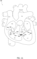
- Figure 11 is a schematic diagram of an example of a double heart valve anchoring system 180 comprising the tricuspid valve replacement 200 and the mitral valve repair 800 coupled to one another via the septum.
- the tricuspid valve replacement 200 and the mitral valve repair 800 can be coupled to the anchor 500 configured to be positioned in a trans-septal opening.
- the mitral valve repair 800 can comprise the connectors 810 configured to couple a native mitral valve leaflet to the anchor 500.
- a connector 900 can couple the tricuspid valve replacement 200 to the anchor 500.
- a first end 902 of the connector 900 can be coupled to the tricuspid valve replacement 200, such as a second distal end 204 of the tricuspid valve replacement 200.
- a second end 904 of the connector 900 can be coupled to the anchor 500.
- FIG. 12 a schematic diagram is shown of a double heart valve anchoring system 190 comprising an example of a tricuspid valve replacement 1000 and an example of mitral valve replacement 1100.
- a connector 400 can couple the tricuspid valve replacement 1000 and the mitral valve replacement 1100 to one another.
- a corresponding portion of the connector 400 can extend through the anchor 500 configured to be positioned in a trans-septal opening.
- the tricuspid valve replacement 1000 can comprise a tricuspid valve body portion 1006 comprising a first distal end 1002 and a second distal end 1004.
- the mitral valve replacement 1100 can comprise a mitral valve body portion 1106 comprising a first distal end 1102 and a second distal end 1104.
- the first distal end 1002 of the tricuspid valve replacement 1000, and the first distal end 1102 of the mitral valve replacement 1100 can be oriented towards the right atrium and left atrium, respectively.
- the second distal ends 1004, 1104 can be oriented toward the right ventricle and left ventricle, respectively.
- the tricuspid valve replacement 1000 can comprise a frame 1008 and valve tissue 1010.
- the mitral valve replacement 1100 can comprise a frame 1108 and valve tissue 1110.
- a first portion 402 of the connector 400 can be coupled to the second distal end 1004 of the tricuspid valve replacement 1000 and a second portion 404 of the connector 400 can be coupled to the second distal end 1104 of the mitral valve replacement 1100.
- the connector 400 can be coupled to the frames 1008, 1108 of the tricuspid valve replacement 1000 and the mitral valve replacement 1100 at their respective second distal ends 1004, 1104.
- the frames 1008, 1108 can comprise one or more features to facilitate attachment of the connector 400 thereto.
- the double heart valve anchoring system 190 can comprise one or more other features as described herein.
- the double heart valve anchoring system 190 can comprise a plurality of connectors 400.
- the double heart valve anchoring system 190 can comprise one or more adjustable connectors 420.
- the double heart valve anchoring system 190 can comprise one or more of the connectors 430 comprising a rigid or semi-rigid portion 436.
- the double heart valve anchoring system 190 can comprise the anchor 550 rather than the anchor 500.
- one or more heart valve replacements described herein can be one or more commercially available heart valve replacements (e.g., Sapien 3 TM , CardiAQ TM , and Centera TM , commercially available from Edwards Lifesciences LLC, Irvine, CA).
- one or more of the double heart valve anchoring systems as described herein may not comprise an anchor.
- the connector(s) described with reference to Figures 5A , 6 , 7A , 8 , 9 , 10 , 11 and 12 can extend through the trans-septal opening without extending through any anchors.
- a procedure for positioning a double heart valve anchoring system at its target site can comprise inserting and retracting a double heart valve anchoring system delivery catheter along the same or similar path.
- Using one path for both the insertion and retraction of the delivery catheter to deploy both a tricuspid valve replacement and a mitral valve replacement anchored to the septum can, for example, enable a simpler minimally invasive transcatheter approach, reduce trauma to the patient, and/or facilitate an improved patient recovery process.
- Figures 13A and 13B are schematic diagrams showing an example of a path along which a delivery catheter carrying a double heart valve anchoring system can be advanced and retracted to position the double heart valve anchoring system at its target site.
- the double heart valve anchoring system can have one or more features described herein (e.g., the double heart valve anchoring systems 100, 110, 120, 130, 140, 150, 190).
- the double heart valve anchoring system can comprise a tricuspid valve replacement and a mitral valve replacement, and a connector coupling the tricuspid valve replacement and the mitral valve replacement to one another.
- the connector can extend through an anchor configured to be positioned in a trans-septal opening.
- Figure 13A shows the path along which the delivery catheter is inserted
- Figure 13B shows the path along which the delivery catheter is retracted.
- the delivery catheter carrying the double heart valve anchoring system can be advanced through the inferior vena cava (IVC).
- IVC inferior vena cava
- a trans-femoral approach can be used, inserting the delivery catheter through the femoral vein to the inferior vena cava.
- a distal end of the delivery catheter can be extended from the inferior vena cava into the right atrium (RA).
- the distal end of the delivery catheter can then be inserted through an opening formed by the native tricuspid valve and advanced from the right atrium into the right ventricle (RV).
- RV right ventricle
- the delivery catheter can be extended into the left ventricle (LV) from the right ventricle via a trans-septal opening formed in the septum.
- the distal end of the delivery catheter can be positioned at the target site for the mitral valve replacement and the mitral valve replacement can be deployed at its target position.
- the delivery catheter can be retracted towards the right ventricle.
- the delivery catheter can be retracted along the same or substantially the same path along which the delivery catheter was advanced.
- a corresponding portion of the connector can be released in the left ventricle from the distal end of the delivery catheter.
- the distal end of the delivery catheter can then be withdrawn through the trans-septal opening from the left ventricle back into the right ventricle (RV), leaving the anchor at its target site.
- At least a portion of the anchor and a corresponding portion of the connector can be positioned in the trans-septal opening as the delivery catheter is moved back through the trans-septal opening. Subsequently, a corresponding portion of the connector can be released in the right ventricle as the distal end of the delivery catheter is retracted through the right ventricle toward the right atrium. The distal end of the delivery catheter can then be positioned at a desired location for the tricuspid valve replacement. After positioning the distal end of the delivery catheter at the desired location for the tricuspid valve replacement, the tricuspid valve replacement can be deployed at its target site. The delivery catheter can then be withdrawn into the right atrium, and removed through the inferior vena cava.
- Figures 14A and 14B are schematic diagrams showing another example of a path along which a delivery catheter carrying a double heart valve anchoring system can be advanced and retracted to position the double heart valve anchoring system at its target site.
- the double heart valve anchoring system can have one or more features described herein (e.g., the double heart valve anchoring systems 100, 110, 120, 130, 140, 150, 190), such as a connector coupling a tricuspid valve replacement and a mitral valve replacement, and the connector extending through an anchor.
- Figure 14A shows the path along which the delivery catheter can be inserted
- Figure 14B shows the path along which the delivery catheter can be retracted.
- the delivery catheter carrying the double heart valve anchoring system can be advanced through the superior vena cava (SVC).
- SVC superior vena cava
- a trans-subclavian or trans-jugular approach can be used, inserting the delivery catheter through the subclavian vein or the jugular vein to the superior vena cava.
- a distal end of the delivery catheter can be extended from the superior vena cava into the right atrium (RA), and then from the right atrium through an opening formed by the native tricuspid valve into the right ventricle (RV).
- RV right atrium
- RV right atrium
- RV right ventricle
- the delivery catheter can be extended into the left ventricle (LV) from the right ventricle via a trans-septal opening formed in the septum.
- the distal end of the delivery catheter can be positioned at the target site for the mitral valve replacement.
- the mitral valve replacement can then be deployed at its target position.
- the delivery catheter can be retracted towards the right ventricle.
- the delivery catheter can be retracted along the same or substantially the same path along which the delivery catheter was advanced.
- a corresponding portion of the connector can be released in the left ventricle from the distal end of the delivery catheter.
- the distal end of the delivery catheter can then be withdrawn through the trans-septal opening into the right ventricle (RV).
- the anchor can be released at its target site in the trans-septal opening, along with a corresponding portion of the connector.
- a corresponding portion of the connector can be released in the right ventricle as the distal end of the delivery catheter is retracted through the right ventricle toward the right atrium.
- the distal end of the delivery catheter can then be positioned at a desired location for the tricuspid valve replacement, and the tricuspid valve replacement can be deployed.
- the delivery catheter can then be withdrawn into the right atrium, and removed through the superior vena cava.
- Figure 15 is a flow diagram showing an example of an implantation procedure 1500 for positioning a double heart valve anchoring system as its target site.
- the double heart valve anchoring system can be carried by a delivery catheter.
- the double heart valve anchoring system can comprise one or more features described herein (e.g., the double heart valve anchoring systems 100, 110, 120, 130, 140, 150, 190), for example comprising a connector coupling a tricuspid valve replacement and a mitral valve replacement.
- the double heart valve anchoring system comprises an anchor such that the connector extends through the anchor.
- the double heart valve anchoring system does not include an anchor.
- the delivery catheter can be introduced through an inferior vena cava or a superior vena cava, and into a right atrium.
- the delivery catheter can be advanced from the right atrium into the right ventricle via an opening formed by a native tricuspid valve.
- the delivery catheter can be advanced through the right ventricle toward the left ventricle.
- the delivery catheter can be threaded through a trans-septal opening in an interventricular septum to insert the delivery catheter into the left ventricle from the right ventricle.
- the trans-septal opening can be pre-formed, for example being formed prior to insertion of the delivery catheter into the superior vena cava or the inferior vena cava.
- the trans-septal opening can be formed by one or more instruments also carried by the delivery catheter. For example, the trans-septal opening can be formed during advancement of the delivery catheter through the septum.
- the delivery catheter After moving through the trans-septal opening, the delivery catheter can be advanced through the left ventricle toward the native mitral valve.
- a distal end of the delivery catheter can be positioned at a target site for the mitral valve replacement.
- the mitral valve replacement can be released at its target site. The mitral valve replacement can be deployed from the distal end of the delivery catheter and positioned at its desired location in the native mitral valve.
- the delivery catheter can be retracted along a path the same as or substantially the same as the path along which it was advanced.
- the delivery catheter can be retracted through the left ventricle, the trans-septal opening and into the right ventricle.
- respective portions of the connector can be released in the left ventricle, the trans-septal opening and the right ventricle while retracting the delivery catheter through the left ventricle, the trans-septal opening and into the right ventricle.
- the double heart valve anchoring system can comprise an anchor.
- the anchor can be between the tricuspid valve replacement and the mitral valve replacement and coupled to the connector.
- the connector can extend through an opening of the anchor. At least a portion of the anchor and a corresponding portion of the connector can be deployed in the trans-septal opening during retracting of the delivery catheter through the trans-septal opening.
- the anchor can comprise an occluder configured to facilitate sealing of the trans-septal opening. For example, releasing at least a portion of the anchor and the corresponding portion of the connector in the trans-septal opening can comprise sealing the trans-septal opening.
- the trans-septal opening can be sealed once the anchor, comprising a corresponding portion of the connector threaded therethrough, is positioned at its target site.
- the delivery catheter can be withdrawn back through the right ventricle toward the right atrium.
- the distal end of the delivery catheter can be positioned at a target site for the tricuspid valve replacement after retracting the delivery catheter into the right ventricle.
- the tricuspid valve replacement can be released at its target site.
- the delivery catheter can be withdrawn through the right atrium and subsequently removed from the heart along the same path as was used in advancing the delivery catheter, such as via the superior vena cava or the inferior vena cava.
- a double heart valve anchoring system can comprise a plurality of connectors.
- the double heart valve anchoring system can comprise one or more additional connectors coupling the tricuspid valve replacement and the mitral valve replacement to one another, such as a second connector. Retracting the delivery catheter through the left ventricle, the trans-septal opening and into the right ventricle can comprise releasing respective portions of both connectors in the left ventricle, the trans-septal opening and the right ventricle.
- the double heart valve anchoring system can include an anchor comprising at least a portion configured to be positioned in the trans-septal opening.
- both connectors can extend through the anchor.
- Retracting the delivery catheter through the left ventricle, the trans-septal opening and into the right ventricle can comprise releasing respective portions of both connectors in the left ventricle, the trans-septal opening and the right ventricle, and placing the anchor at its target position in the trans-septal opening.
- a connector can comprise an adjustable length.
- the length of the connector can be adjusted during the implantation procedure, such as in response to individual anatomy.
- one or more imaging techniques can be employed during the procedure in determining an appropriate length of the connector.
- the implantation procedure can be performed under guidance of one or more of transesophageal (TEE) echocardiography, transthoracic echocardiography (TTE) and intracardiac echocardiography (ICE).
- TEE transesophageal
- TTE transthoracic echocardiography
- ICE intracardiac echocardiography
- Other known visualization techniques may be employed in addition or in the alternative.
- a length of one or more connectors of a double heart valve anchoring system can be adjusted after insertion of the one or more connectors into the patient, with the aid of one or more imaging techniques.
- the length of the one or more connectors can be selected based on individual anatomy so as to provide desired anchoring to the septum.
- the length of a connector can be adjusted such that the connector is taut during ventricular systole.
- the length of the one or more connectors can be adjusted after introducing the delivery catheter into the superior vena cava or inferior vena cava. In some embodiments, the length of the one or more connectors can be adjusted after all replacement valves are positioned at their respective target sites. For example, the length of the one or more connectors can be adjusted after a tricuspid valve replacement is placed at its desired position. In some embodiments, the length of the one or more connectors can be adjusted multiple times. For example, the length of a connector can be adjusted after one or more of positioning a mitral valve replacement, an anchor and a tricuspid valve replacement at their respective target locations.
- the length of a connector can be adjusted after one or more of its corresponding portions are released from the delivery catheter.
- the length of a connector can be adjusted at one or more of: after deployment of the mitral valve replacement and before deployment of the anchor (e.g., after a corresponding portion of the connector has been released in the left ventricle), after deployment of the anchor and before further retraction of the delivery catheter, after deployment of the anchor and before deployment of the tricuspid valve replacement (e.g., after a corresponding portion of the connector has been released in the right ventricle), after deployment of the tricuspid valve replacement.
- the length of a connector can be adjusted after each of its corresponding portions are released from the delivery catheter.
- a locking mechanism can be deployed, activated and/or triggered to secure a connector at a selected length after the appropriate length has been determined during the implantation procedure.
- a locking mechanism can be deployed, activated and/or triggered after each adjustment.
- the double heart valve anchoring system can comprise multiple locking mechanisms.
- a locking mechanism can be deployed, activated and/or triggered after one or more portions of the connector is released and adjusted, including after each portion is released and adjusted.
- indefinite articles may indicate “one or more” rather than “one.”
- an operation performed "based on” a condition or event may also be performed based on one or more other conditions or events not explicitly recited.
- spatially relative terms “outer,” “inner,” “upper,” “lower,” “below,” “above,” “vertical,” “horizontal,” and similar terms, may be used herein for ease of description to describe the relations between one element or component and another element or component as illustrated in the drawings. It be understood that the spatially relative terms are intended to encompass different orientations of the device in use or operation, in addition to the orientation depicted in the drawings. For example, in the case where a device shown in the drawing is turned over, the device positioned “below” or “beneath” another device may be placed “above” another device. Accordingly, the illustrative term “below” may include both the lower and upper positions. The device may also be oriented in the other direction, and thus the spatially relative terms may be interpreted differently depending on the orientations.
Landscapes
- Health & Medical Sciences (AREA)
- Cardiology (AREA)
- Engineering & Computer Science (AREA)
- Biomedical Technology (AREA)
- Heart & Thoracic Surgery (AREA)
- Transplantation (AREA)
- Oral & Maxillofacial Surgery (AREA)
- Vascular Medicine (AREA)
- Life Sciences & Earth Sciences (AREA)
- Animal Behavior & Ethology (AREA)
- General Health & Medical Sciences (AREA)
- Public Health (AREA)
- Veterinary Medicine (AREA)
- Prostheses (AREA)
Claims (15)
- Doppeltes Herzklappenverankerungssystem (100; 120; 130; 140; 150; 160; 170; 180; 190;), umfassend:einen ersten Anker (500, 550), der mindestens einen Abschnitt umfasst, welcher dazu konfiguriert ist, in einer ersten transseptalen Öffnung in einem interventrikulären Septum (10) befestigt zu werden;eine Trikuspidalklappenvorrichtung, die mittels eines ersten Verbinders (400; 420; 430) mit dem ersten Anker (500; 550) verbunden ist; undeine Mitralklappenvorrichtung, die mittels des ersten Verbinders (400; 420; 430) mit dem ersten Anker (500; 550) verbunden ist.
- System nach Anspruch 1, wobei die Trikuspidalklappenvorrichtung einen Trikuspidalklappenersatz (200) umfasst und die Mitralklappenvorrichtung einen Mitralklappenersatz (300) umfasst.
- System nach Anspruch 2, wobei der erste Verbinder (400; 420; 430) sich zwischen dem Trikuspidalklappenersatz (200) und dem Mitralklappenersatz (300) erstreckt, den Trikuspidalklappenersatz (200) und den Mitralklappenersatz (300) mit dem ersten Anker (500; 550) verbindet, und dazu konfiguriert ist, sich durch die erste transseptale Öffnung zu erstrecken.
- System nach Anspruch 3, das ferner einen zweiten Verbinder (400; 420, 430) umfasst, der sich zwischen dem Trikuspidalklappenersatz (200) und dem Mitralklappenersatz (300) erstreckt und der den Trikuspidalklappenersatz (200) mit dem Mitralklappenersatz (300) verbindet, wobei sowohl der erste Verbinder (400; 420; 430) als auch der zweite Verbinder (400; 420; 430) den Trikuspidalklappenersatz (200) und den Mitralklappenersatz (300) mit dem ersten Anker (500; 550) verbinden und beide dazu konfiguriert sind, sich durch die erste transseptale Öffnung zu erstrecken.
- System nach Anspruch 4, wobei das System insbesondere ferner einen zweiten Anker (500; 550) umfasst, der wenigstens einen Abschnitt umfasst, welcher dazu konfiguriert ist, in einer zweiten transseptalen Öffnung im interventrikulären Septum (10) befestigt zu werden, und wobei der zweite Verbinder (400; 420; 430) den Trikuspidalklappenersatz (200) und den Mitralklappenersatz (300) mit dem zweiten Anker (500; 550) verbindet.
- System nach einem der Ansprüche 4 bis 5, wobei die entsprechenden Enden von mindestens einem von dem ersten Verbinder (400; 420; 430) und dem zweiten Verbinder (400, 420, 430) mit einem Abschnitt des Trikuspidalklappenersatzes (200) verbunden sind, der dazu konfiguriert ist, im rechten Ventrikel (4) positioniert zu werden, sowie mit einem Abschnitt des Mitralklappenersatzes (300) verbunden sind, der dazu konfiguriert ist, im linken Ventrikel (3) positioniert zu werden,
wobei die entsprechenden Enden von dem mindestens einem von dem ersten Verbinder (400; 420; 430) und dem zweiten Verbinder (400; 420; 430 insbesondere mit einem distalen Ende (202, 204) des Trikuspidalklappenersatzes (200) verbunden sind, das dazu konfiguriert ist, im rechten Ventrikel (4) positioniert zu werden, und mit einem distalen Ende (302, 304) des Mitralklappenersatzes (300) verbunden sind, das dazu konfiguriert ist, im linken Ventrikel (3) positioniert zu werden. - System nach einem der Ansprüche 4 bis 6, wobei eine Länge von dem mindestens einem von dem ersten Verbinder (400; 420; 430) und dem zweiten Verbinder (400, 420; 430) einstellbar ist, und
wobei das System insbesondere ferner mindestens einen Verriegelungsmechanismus (600) zur Verriegeln von mindestens dem ersten Verbinder (400; 420; 430) oder dem zweiten Verbinder (400, 420; 430) auf eine entsprechend ausgewählte Länge umfasst. - System nach einem der Ansprüche 4 bis 7, wobei mindestens einer von dem ersten Verbinder (400; 420; 430) und dem zweiten Verbinder (400; 420; 430) einen starren Verbinderabschnitt (436) umfasst, wobei der starre Verbinderabschnitt (436) dazu konfiguriert ist, sich durch das Septum (10) in mindestens eines von dem rechten Ventrikel (4) und dem linken Ventrikel (3) zu erstrecken um vorbestimmte Verankerungswinkel am Septum (10) für den Trikuspidalklappenersatz (200) und den Mitralklappenersatz (300) bereitzustellen, oder zumindest einer von dem ersten Verbinder (400; 420; 430) und dem zweiten Verbinder (400, 420; 430) eine flexible Schnur ist.
- System nach Anspruch 1, wobei die Trikuspidalklappenvorrichtung einen Trikuspidalklappenersatz (200) umfasst und die Mitralklappenvorrichtung eine Mitralklappenausbesserung (800) umfasst, oder die Trikuspidalklappenvorrichtung eine Trikuspidalklappenausbesserung (700) umfasst und die Mitralklappenvorrichtung einen Mitralklappenersatz (300) umfasst, oder die Trikuspidalklappenvorrichtung eine Trikuspidalklappenausbesserung (700) umfasst und die Mitralklappenvorrichtung eine Mitralklappenausbesserung (800) umfasst.
- Doppeltes Herzklappenverankerungssystem (100; 110; 120; 130; 140, 150; 160; 170; 180; 190), umfassend:einen Trikuspidalklappenersatz (200);einen Mitralklappenersatz (300), undeinen ersten Verbinder (400; 410; 420; 430), der den Trikuspidalklappenersatz (200) und den Mitralklappenersatz (300) verbindet und dazu konfiguriert ist, sich durch eine erste transseptale Öffnung in einem interventrikulären Septum (10) zu erstecken ohne mit irgendeinem Anker, der in und/oder durch ein Septum positioniert ist, verbunden zu sein.
- System nach Anspruch 10, ferner einen zweiten Verbinder (400; 410; 420, 430) umfassend, der mit dem Trikuspidalklappenersatz (200) und dem Mitralklappenersatz (300) verbunden ist.
- System nach Anspruch 11, wobei sowohl der erste Verbinder (400; 410; 420, 430) als auch der zweite Verbinder (400; 410; 420, 430) dazu konfiguriert sind, sich durch eine erste transseptale Öffnung zu erstrecken,
wobei der zweite Verbinder (400; 410; 420, 430) insbesondere dazu konfiguriert ist, sich durch eine zweite transseptale Öffnung zu erstrecken. - System nach einem der Ansprüche 11 bis 12, wobei die entsprechenden Enden von mindestens dem ersten Verbinder (400, 410; 420; 430) oder dem zweiten Verbinder (400; 410, 420; 430) mit einem Abschnitt des Trikuspidalklappenersatzes (200), der dazu konfiguriert ist, in einem rechten Ventrikel (4) positioniert zu werden, verbunden ist und mit einem Abschnitt des Mitralklappenersatzes (300), der dazu konfiguriert ist, in einem linken Ventrikel (3) positioniert zu werden, verbunden ist,
wobei, die entsprechenden Enden von mindestens dem ersten Verbinder (400; 410; 420; 430) oder dem zweiten Verbinder (400; 410, 420; 430) insbesondere mit einem distalen Ende (202, 204) des Trikuspidalklappenersatzes (200), das dazu konfiguriert ist, im rechten Ventrikel (4) positioniert zu werden, verbunden ist und mit einem distalen Ende (302,304) des Mitralklappenersatzes, das dazu konfiguriert ist, im linken Ventrikel (3) positioniert zu werden, verbunden ist. - System nach einem der Ansprüche 11 bis 13, wobei eine Länge von mindestens einem von dem ersten Verbinder (400; 410, 420; 430) und dem zweiten Verbinder (400, 410, 420; 430) einstellbar ist, und
wobei das System insbesondere ferner mindestens einen Verriegelungsmechanismus (600) zum Verriegeln von mindestens einem von dem ersten Verbinder (400; 410, 420; 430) und dem zweiten Verbinder (400; 410, 420, 430) auf eine jeweils ausgewählte Länge umfasst. - System nach einem der Ansprüche 11 bis 14, wobei mindestens einer von dem ersten Verbinder (400; 410, 420, 430) und dem zweiten Verbinder (400, 410; 420, 430) einen starren Verbinderabschnitt (436) umfasst, wobei der starre Verbinderabschnitt (436) dazu konfiguriert ist, sich durch das interventrikuläre Septum (10) und in mindestens eines von dem rechten Ventrikel (4) und dem linken Ventrikel (3) zu erstrecken, um vorbestimmte Verankerungswinkel am Septum (10) für den Trikuspidalklappenersatz (200) und den Mitralklappenersatz (300) bereitzustellen, und/oder mindestens einer von dem ersten Verbinder (400; 410, 420; 430) und dem zweiten Verbinder (400, 410, 420; 430) eine flexible Schnur ist.
Applications Claiming Priority (2)
| Application Number | Priority Date | Filing Date | Title |
|---|---|---|---|
| US201962811453P | 2019-02-27 | 2019-02-27 | |
| PCT/US2020/016928 WO2020176208A1 (en) | 2019-02-27 | 2020-02-06 | Double heart valve anchoring |
Publications (2)
| Publication Number | Publication Date |
|---|---|
| EP3930628A1 EP3930628A1 (de) | 2022-01-05 |
| EP3930628B1 true EP3930628B1 (de) | 2023-08-02 |
Family
ID=69771135
Family Applications (1)
| Application Number | Title | Priority Date | Filing Date |
|---|---|---|---|
| EP20709898.9A Active EP3930628B1 (de) | 2019-02-27 | 2020-02-06 | Doppelte herzklappenverankerung |
Country Status (5)
| Country | Link |
|---|---|
| US (1) | US20210378817A1 (de) |
| EP (1) | EP3930628B1 (de) |
| JP (2) | JP7621959B2 (de) |
| CN (2) | CN113710202B (de) |
| WO (1) | WO2020176208A1 (de) |
Families Citing this family (30)
| Publication number | Priority date | Publication date | Assignee | Title |
|---|---|---|---|---|
| JP2008513060A (ja) | 2004-09-14 | 2008-05-01 | エドワーズ ライフサイエンシーズ アーゲー | 心臓弁逆流の処置のためのデバイスおよび方法 |
| US20090276040A1 (en) | 2008-05-01 | 2009-11-05 | Edwards Lifesciences Corporation | Device and method for replacing mitral valve |
| WO2010057262A1 (en) | 2008-11-21 | 2010-05-27 | Percutaneous Cardiovascular Solutions Pty Limited | Heart valve prosthesis and method |
| EP4119098A1 (de) | 2009-04-15 | 2023-01-18 | Edwards Lifesciences CardiAQ LLC | Gefässimplantat und freisetzungssystem |
| CA2760461C (en) | 2009-04-29 | 2014-10-07 | The Cleveland Clinic Foundation | Apparatus and method for replacing a diseased cardiac valve |
| US8449599B2 (en) | 2009-12-04 | 2013-05-28 | Edwards Lifesciences Corporation | Prosthetic valve for replacing mitral valve |
| US8475525B2 (en) * | 2010-01-22 | 2013-07-02 | 4Tech Inc. | Tricuspid valve repair using tension |
| US8579964B2 (en) | 2010-05-05 | 2013-11-12 | Neovasc Inc. | Transcatheter mitral valve prosthesis |
| WO2012040655A2 (en) | 2010-09-23 | 2012-03-29 | Cardiaq Valve Technologies, Inc. | Replacement heart valves, delivery devices and methods |
| US12502276B2 (en) | 2011-05-16 | 2025-12-23 | Edwards Lifesciences Corporation | Inversion delivery device and method for a prosthesis |
| US9439763B2 (en) | 2013-02-04 | 2016-09-13 | Edwards Lifesciences Corporation | Prosthetic valve for replacing mitral valve |
| US20140277427A1 (en) | 2013-03-14 | 2014-09-18 | Cardiaq Valve Technologies, Inc. | Prosthesis for atraumatically grasping intralumenal tissue and methods of delivery |
| WO2015127283A1 (en) | 2014-02-21 | 2015-08-27 | Cardiaq Valve Technologies, Inc. | Delivery device for controlled deployement of a replacement valve |
| US9532870B2 (en) | 2014-06-06 | 2017-01-03 | Edwards Lifesciences Corporation | Prosthetic valve for replacing a mitral valve |
| BR112017006248A2 (pt) | 2014-09-28 | 2017-12-12 | Cardiokinetix Inc | aparelhos para o tratamento de insuficiência cardíaca |
| US10531951B2 (en) | 2014-11-26 | 2020-01-14 | Edwards Lifesciences Corporation | Transcatheter prosthetic heart valve and delivery system |
| WO2016153918A1 (en) | 2015-03-20 | 2016-09-29 | Cardiokinetix, Inc. | Systems and methods for delivering an implantable device |
| US10441416B2 (en) | 2015-04-21 | 2019-10-15 | Edwards Lifesciences Corporation | Percutaneous mitral valve replacement device |
| US10350062B2 (en) | 2016-07-21 | 2019-07-16 | Edwards Lifesciences Corporation | Replacement heart valve prosthesis |
| US10639143B2 (en) | 2016-08-26 | 2020-05-05 | Edwards Lifesciences Corporation | Multi-portion replacement heart valve prosthesis |
| EP3648708A4 (de) | 2017-07-06 | 2021-03-31 | Edwards Lifesciences Corporation | Steuerbares abgabesystem und komponenten |
| EP3720390B1 (de) | 2018-01-25 | 2024-05-01 | Edwards Lifesciences Corporation | Einführsystem zur unterstützten rückgewinnung oder neupositionierung eines klappenersatzes nach dem einsetzen |
| EP3921012A1 (de) | 2019-02-04 | 2021-12-15 | Edwards Lifesciences Corporation | Führungsdrahtvorrichtungen und verfahren |
| EP3952790A1 (de) | 2019-04-12 | 2022-02-16 | W.L. Gore & Associates, Inc. | Ventil mit mehrteiligem rahmen und zugehörigen elastischen überbrückungsmerkmalen |
| ES2982566T3 (es) | 2019-04-23 | 2024-10-16 | Edwards Lifesciences Corp | Sistema de suministro de implantes motorizado |
| WO2022132569A1 (en) | 2020-12-18 | 2022-06-23 | Edwards Lifesciences Corporation | Storage jar assembly for aprosthetic heart valve |
| BR112023018994A2 (pt) * | 2021-03-25 | 2023-11-28 | Edwards Lifesciences Innovation Israel Ltd | Implantes de contração de tecido para válvulas cardíacas |
| KR102918984B1 (ko) | 2021-10-27 | 2026-01-28 | 에드워즈 라이프사이언시스 코포레이션 | 인공 심장 판막의 클림핑 및 로딩을 위한 시스템 및 방법 |
| WO2023212245A1 (en) | 2022-04-29 | 2023-11-02 | Tangent Biotech Inc. | Percutaneous tricuspid valve repair devices and methods |
| CN116211544B (zh) * | 2023-03-06 | 2026-04-24 | 复旦大学附属中山医院 | 一种瓣膜血流调节装置 |
Family Cites Families (12)
| Publication number | Priority date | Publication date | Assignee | Title |
|---|---|---|---|---|
| US20050222489A1 (en) * | 2003-10-01 | 2005-10-06 | Ample Medical, Inc. | Devices, systems, and methods for reshaping a heart valve annulus, including the use of a bridge implant |
| SE531468C2 (sv) * | 2005-04-21 | 2009-04-14 | Edwards Lifesciences Ag | En anordning för styrning av blodflöde |
| WO2007067820A2 (en) * | 2005-12-09 | 2007-06-14 | Edwards Lifesciences Corporation | Improved anchoring system for medical implant |
| US20070203391A1 (en) * | 2006-02-24 | 2007-08-30 | Medtronic Vascular, Inc. | System for Treating Mitral Valve Regurgitation |
| US9795482B2 (en) * | 2010-04-27 | 2017-10-24 | Medtronic, Inc. | Prosthetic heart valve devices and methods of valve repair |
| US9770232B2 (en) * | 2011-08-12 | 2017-09-26 | W. L. Gore & Associates, Inc. | Heart occlusion devices |
| EP2567663A1 (de) * | 2011-09-09 | 2013-03-13 | Occlutech Holding AG | Faltbare medizinische Verschlussvorrichtung, Verfahren und medizinisches System zur Abgabe eines Objekts |
| US9066800B2 (en) * | 2012-03-28 | 2015-06-30 | Medtronic, Inc. | Dual valve prosthesis for transcatheter valve implantation |
| EP2732796A1 (de) * | 2012-11-20 | 2014-05-21 | Nakostech Sarl | Mitralklappenersatzsystem |
| WO2016108181A1 (en) * | 2014-12-30 | 2016-07-07 | Tel Hashomer Medical Research, Infrastructure And Services Ltd. | Cardiac prostheses |
| EP3184081B1 (de) * | 2015-12-22 | 2021-03-24 | Medira Ag | Prothetische koaptationsverbesserungsvorrichtung für mitralklappe |
| CN121796784A (zh) * | 2015-12-30 | 2026-04-07 | 管道医疗技术股份有限公司 | 二尖瓣瓣叶拴系 |
-
2020
- 2020-02-06 EP EP20709898.9A patent/EP3930628B1/de active Active
- 2020-02-06 CN CN202080027534.7A patent/CN113710202B/zh active Active
- 2020-02-06 WO PCT/US2020/016928 patent/WO2020176208A1/en not_active Ceased
- 2020-02-06 JP JP2021550041A patent/JP7621959B2/ja active Active
- 2020-02-06 CN CN202411794784.XA patent/CN119606604A/zh active Pending
-
2021
- 2021-08-24 US US17/410,732 patent/US20210378817A1/en active Pending
-
2025
- 2025-01-15 JP JP2025005540A patent/JP2025065152A/ja active Pending
Also Published As
| Publication number | Publication date |
|---|---|
| CN113710202B (zh) | 2024-12-27 |
| JP2022522178A (ja) | 2022-04-14 |
| EP3930628A1 (de) | 2022-01-05 |
| WO2020176208A1 (en) | 2020-09-03 |
| JP7621959B2 (ja) | 2025-01-27 |
| JP2025065152A (ja) | 2025-04-17 |
| US20210378817A1 (en) | 2021-12-09 |
| CN113710202A (zh) | 2021-11-26 |
| CN119606604A (zh) | 2025-03-14 |
Similar Documents
| Publication | Publication Date | Title |
|---|---|---|
| EP3930628B1 (de) | Doppelte herzklappenverankerung | |
| US12115064B2 (en) | Systems and methods for heart valve therapy | |
| US12310845B2 (en) | Docking elements | |
| US12350153B2 (en) | Systems and methods for transcatheter treatment of valve regurgitation | |
| CN109310500B (zh) | 心脏瓣膜修复设备及其植入方法 | |
| JP2024026388A (ja) | 埋込可能な心臓弁デバイス、僧帽弁修復デバイス、ならびに関連するシステム及び方法 | |
| EP3017792B1 (de) | Systeme für herzklappentherapie | |
| US11793628B2 (en) | Transcatheter bio-prosthesis member and support structure | |
| US20080039935A1 (en) | Methods and apparatus for mitral valve repair | |
| US20110077733A1 (en) | Leaflet contacting apparatus and method | |
| CN114848235A (zh) | 用于心脏瓣膜的假体间隔件装置 | |
| EP4017421A1 (de) | Herzklappensegelverankerung | |
| HK40066551B (en) | Double heart valve anchoring | |
| HK40066551A (en) | Double heart valve anchoring | |
| CN117677341A (zh) | 感测式心脏瓣膜修复装置 |
Legal Events
| Date | Code | Title | Description |
|---|---|---|---|
| STAA | Information on the status of an ep patent application or granted ep patent |
Free format text: STATUS: UNKNOWN |
|
| STAA | Information on the status of an ep patent application or granted ep patent |
Free format text: STATUS: THE INTERNATIONAL PUBLICATION HAS BEEN MADE |
|
| PUAI | Public reference made under article 153(3) epc to a published international application that has entered the european phase |
Free format text: ORIGINAL CODE: 0009012 |
|
| STAA | Information on the status of an ep patent application or granted ep patent |
Free format text: STATUS: REQUEST FOR EXAMINATION WAS MADE |
|
| 17P | Request for examination filed |
Effective date: 20210927 |
|
| AK | Designated contracting states |
Kind code of ref document: A1 Designated state(s): AL AT BE BG CH CY CZ DE DK EE ES FI FR GB GR HR HU IE IS IT LI LT LU LV MC MK MT NL NO PL PT RO RS SE SI SK SM TR |
|
| STAA | Information on the status of an ep patent application or granted ep patent |
Free format text: STATUS: EXAMINATION IS IN PROGRESS |
|
| 17Q | First examination report despatched |
Effective date: 20220404 |
|
| DAV | Request for validation of the european patent (deleted) | ||
| DAX | Request for extension of the european patent (deleted) | ||
| REG | Reference to a national code |
Ref country code: HK Ref legal event code: DE Ref document number: 40066551 Country of ref document: HK |
|
| GRAP | Despatch of communication of intention to grant a patent |
Free format text: ORIGINAL CODE: EPIDOSNIGR1 |
|
| STAA | Information on the status of an ep patent application or granted ep patent |
Free format text: STATUS: GRANT OF PATENT IS INTENDED |
|
| INTG | Intention to grant announced |
Effective date: 20230214 |
|
| GRAS | Grant fee paid |
Free format text: ORIGINAL CODE: EPIDOSNIGR3 |
|
| GRAA | (expected) grant |
Free format text: ORIGINAL CODE: 0009210 |
|
| STAA | Information on the status of an ep patent application or granted ep patent |
Free format text: STATUS: THE PATENT HAS BEEN GRANTED |
|
| AK | Designated contracting states |
Kind code of ref document: B1 Designated state(s): AL AT BE BG CH CY CZ DE DK EE ES FI FR GB GR HR HU IE IS IT LI LT LU LV MC MK MT NL NO PL PT RO RS SE SI SK SM TR |
|
| REG | Reference to a national code |
Ref country code: GB Ref legal event code: FG4D |
|
| REG | Reference to a national code |
Ref country code: CH Ref legal event code: EP |
|
| REG | Reference to a national code |
Ref country code: DE Ref legal event code: R096 Ref document number: 602020014924 Country of ref document: DE |
|
| REG | Reference to a national code |
Ref country code: IE Ref legal event code: FG4D |
|
| P01 | Opt-out of the competence of the unified patent court (upc) registered |
Effective date: 20230801 |
|
| REG | Reference to a national code |
Ref country code: LT Ref legal event code: MG9D |
|
| REG | Reference to a national code |
Ref country code: NL Ref legal event code: MP Effective date: 20230802 |
|
| REG | Reference to a national code |
Ref country code: AT Ref legal event code: MK05 Ref document number: 1593821 Country of ref document: AT Kind code of ref document: T Effective date: 20230802 |
|
| PG25 | Lapsed in a contracting state [announced via postgrant information from national office to epo] |
Ref country code: GR Free format text: LAPSE BECAUSE OF FAILURE TO SUBMIT A TRANSLATION OF THE DESCRIPTION OR TO PAY THE FEE WITHIN THE PRESCRIBED TIME-LIMIT Effective date: 20231103 |
|
| PG25 | Lapsed in a contracting state [announced via postgrant information from national office to epo] |
Ref country code: IS Free format text: LAPSE BECAUSE OF FAILURE TO SUBMIT A TRANSLATION OF THE DESCRIPTION OR TO PAY THE FEE WITHIN THE PRESCRIBED TIME-LIMIT Effective date: 20231202 |
|
| PG25 | Lapsed in a contracting state [announced via postgrant information from national office to epo] |
Ref country code: SE Free format text: LAPSE BECAUSE OF FAILURE TO SUBMIT A TRANSLATION OF THE DESCRIPTION OR TO PAY THE FEE WITHIN THE PRESCRIBED TIME-LIMIT Effective date: 20230802 Ref country code: RS Free format text: LAPSE BECAUSE OF FAILURE TO SUBMIT A TRANSLATION OF THE DESCRIPTION OR TO PAY THE FEE WITHIN THE PRESCRIBED TIME-LIMIT Effective date: 20230802 Ref country code: PT Free format text: LAPSE BECAUSE OF FAILURE TO SUBMIT A TRANSLATION OF THE DESCRIPTION OR TO PAY THE FEE WITHIN THE PRESCRIBED TIME-LIMIT Effective date: 20231204 Ref country code: NO Free format text: LAPSE BECAUSE OF FAILURE TO SUBMIT A TRANSLATION OF THE DESCRIPTION OR TO PAY THE FEE WITHIN THE PRESCRIBED TIME-LIMIT Effective date: 20231102 Ref country code: NL Free format text: LAPSE BECAUSE OF FAILURE TO SUBMIT A TRANSLATION OF THE DESCRIPTION OR TO PAY THE FEE WITHIN THE PRESCRIBED TIME-LIMIT Effective date: 20230802 Ref country code: LV Free format text: LAPSE BECAUSE OF FAILURE TO SUBMIT A TRANSLATION OF THE DESCRIPTION OR TO PAY THE FEE WITHIN THE PRESCRIBED TIME-LIMIT Effective date: 20230802 Ref country code: LT Free format text: LAPSE BECAUSE OF FAILURE TO SUBMIT A TRANSLATION OF THE DESCRIPTION OR TO PAY THE FEE WITHIN THE PRESCRIBED TIME-LIMIT Effective date: 20230802 Ref country code: IS Free format text: LAPSE BECAUSE OF FAILURE TO SUBMIT A TRANSLATION OF THE DESCRIPTION OR TO PAY THE FEE WITHIN THE PRESCRIBED TIME-LIMIT Effective date: 20231202 Ref country code: HR Free format text: LAPSE BECAUSE OF FAILURE TO SUBMIT A TRANSLATION OF THE DESCRIPTION OR TO PAY THE FEE WITHIN THE PRESCRIBED TIME-LIMIT Effective date: 20230802 Ref country code: GR Free format text: LAPSE BECAUSE OF FAILURE TO SUBMIT A TRANSLATION OF THE DESCRIPTION OR TO PAY THE FEE WITHIN THE PRESCRIBED TIME-LIMIT Effective date: 20231103 Ref country code: FI Free format text: LAPSE BECAUSE OF FAILURE TO SUBMIT A TRANSLATION OF THE DESCRIPTION OR TO PAY THE FEE WITHIN THE PRESCRIBED TIME-LIMIT Effective date: 20230802 Ref country code: AT Free format text: LAPSE BECAUSE OF FAILURE TO SUBMIT A TRANSLATION OF THE DESCRIPTION OR TO PAY THE FEE WITHIN THE PRESCRIBED TIME-LIMIT Effective date: 20230802 |
|
| PG25 | Lapsed in a contracting state [announced via postgrant information from national office to epo] |
Ref country code: PL Free format text: LAPSE BECAUSE OF FAILURE TO SUBMIT A TRANSLATION OF THE DESCRIPTION OR TO PAY THE FEE WITHIN THE PRESCRIBED TIME-LIMIT Effective date: 20230802 |
|
| PG25 | Lapsed in a contracting state [announced via postgrant information from national office to epo] |
Ref country code: ES Free format text: LAPSE BECAUSE OF FAILURE TO SUBMIT A TRANSLATION OF THE DESCRIPTION OR TO PAY THE FEE WITHIN THE PRESCRIBED TIME-LIMIT Effective date: 20230802 |
|
| PG25 | Lapsed in a contracting state [announced via postgrant information from national office to epo] |
Ref country code: SM Free format text: LAPSE BECAUSE OF FAILURE TO SUBMIT A TRANSLATION OF THE DESCRIPTION OR TO PAY THE FEE WITHIN THE PRESCRIBED TIME-LIMIT Effective date: 20230802 Ref country code: RO Free format text: LAPSE BECAUSE OF FAILURE TO SUBMIT A TRANSLATION OF THE DESCRIPTION OR TO PAY THE FEE WITHIN THE PRESCRIBED TIME-LIMIT Effective date: 20230802 Ref country code: ES Free format text: LAPSE BECAUSE OF FAILURE TO SUBMIT A TRANSLATION OF THE DESCRIPTION OR TO PAY THE FEE WITHIN THE PRESCRIBED TIME-LIMIT Effective date: 20230802 Ref country code: EE Free format text: LAPSE BECAUSE OF FAILURE TO SUBMIT A TRANSLATION OF THE DESCRIPTION OR TO PAY THE FEE WITHIN THE PRESCRIBED TIME-LIMIT Effective date: 20230802 Ref country code: DK Free format text: LAPSE BECAUSE OF FAILURE TO SUBMIT A TRANSLATION OF THE DESCRIPTION OR TO PAY THE FEE WITHIN THE PRESCRIBED TIME-LIMIT Effective date: 20230802 Ref country code: CZ Free format text: LAPSE BECAUSE OF FAILURE TO SUBMIT A TRANSLATION OF THE DESCRIPTION OR TO PAY THE FEE WITHIN THE PRESCRIBED TIME-LIMIT Effective date: 20230802 Ref country code: SK Free format text: LAPSE BECAUSE OF FAILURE TO SUBMIT A TRANSLATION OF THE DESCRIPTION OR TO PAY THE FEE WITHIN THE PRESCRIBED TIME-LIMIT Effective date: 20230802 |
|
| REG | Reference to a national code |
Ref country code: DE Ref legal event code: R097 Ref document number: 602020014924 Country of ref document: DE |
|
| PG25 | Lapsed in a contracting state [announced via postgrant information from national office to epo] |
Ref country code: IT Free format text: LAPSE BECAUSE OF FAILURE TO SUBMIT A TRANSLATION OF THE DESCRIPTION OR TO PAY THE FEE WITHIN THE PRESCRIBED TIME-LIMIT Effective date: 20230802 |
|
| PLBE | No opposition filed within time limit |
Free format text: ORIGINAL CODE: 0009261 |
|
| STAA | Information on the status of an ep patent application or granted ep patent |
Free format text: STATUS: NO OPPOSITION FILED WITHIN TIME LIMIT |
|
| 26N | No opposition filed |
Effective date: 20240503 |
|
| PG25 | Lapsed in a contracting state [announced via postgrant information from national office to epo] |
Ref country code: SI Free format text: LAPSE BECAUSE OF FAILURE TO SUBMIT A TRANSLATION OF THE DESCRIPTION OR TO PAY THE FEE WITHIN THE PRESCRIBED TIME-LIMIT Effective date: 20230802 |
|
| PG25 | Lapsed in a contracting state [announced via postgrant information from national office to epo] |
Ref country code: MC Free format text: LAPSE BECAUSE OF FAILURE TO SUBMIT A TRANSLATION OF THE DESCRIPTION OR TO PAY THE FEE WITHIN THE PRESCRIBED TIME-LIMIT Effective date: 20230802 |
|
| REG | Reference to a national code |
Ref country code: CH Ref legal event code: PL |
|
| PG25 | Lapsed in a contracting state [announced via postgrant information from national office to epo] |
Ref country code: LU Free format text: LAPSE BECAUSE OF NON-PAYMENT OF DUE FEES Effective date: 20240206 |
|
| PG25 | Lapsed in a contracting state [announced via postgrant information from national office to epo] |
Ref country code: CH Free format text: LAPSE BECAUSE OF NON-PAYMENT OF DUE FEES Effective date: 20240229 |
|
| PG25 | Lapsed in a contracting state [announced via postgrant information from national office to epo] |
Ref country code: LU Free format text: LAPSE BECAUSE OF NON-PAYMENT OF DUE FEES Effective date: 20240206 Ref country code: CH Free format text: LAPSE BECAUSE OF NON-PAYMENT OF DUE FEES Effective date: 20240229 |
|
| PG25 | Lapsed in a contracting state [announced via postgrant information from national office to epo] |
Ref country code: BG Free format text: LAPSE BECAUSE OF FAILURE TO SUBMIT A TRANSLATION OF THE DESCRIPTION OR TO PAY THE FEE WITHIN THE PRESCRIBED TIME-LIMIT Effective date: 20230802 |
|
| PG25 | Lapsed in a contracting state [announced via postgrant information from national office to epo] |
Ref country code: BG Free format text: LAPSE BECAUSE OF FAILURE TO SUBMIT A TRANSLATION OF THE DESCRIPTION OR TO PAY THE FEE WITHIN THE PRESCRIBED TIME-LIMIT Effective date: 20230802 |
|
| REG | Reference to a national code |
Ref country code: BE Ref legal event code: MM Effective date: 20240229 |
|
| PG25 | Lapsed in a contracting state [announced via postgrant information from national office to epo] |
Ref country code: BE Free format text: LAPSE BECAUSE OF NON-PAYMENT OF DUE FEES Effective date: 20240229 |
|
| PG25 | Lapsed in a contracting state [announced via postgrant information from national office to epo] |
Ref country code: FR Free format text: LAPSE BECAUSE OF NON-PAYMENT OF DUE FEES Effective date: 20240229 |
|
| PG25 | Lapsed in a contracting state [announced via postgrant information from national office to epo] |
Ref country code: IE Free format text: LAPSE BECAUSE OF NON-PAYMENT OF DUE FEES Effective date: 20240206 |
|
| PG25 | Lapsed in a contracting state [announced via postgrant information from national office to epo] |
Ref country code: IE Free format text: LAPSE BECAUSE OF NON-PAYMENT OF DUE FEES Effective date: 20240206 Ref country code: FR Free format text: LAPSE BECAUSE OF NON-PAYMENT OF DUE FEES Effective date: 20240229 Ref country code: BE Free format text: LAPSE BECAUSE OF NON-PAYMENT OF DUE FEES Effective date: 20240229 |
|
| PG25 | Lapsed in a contracting state [announced via postgrant information from national office to epo] |
Ref country code: CY Free format text: LAPSE BECAUSE OF FAILURE TO SUBMIT A TRANSLATION OF THE DESCRIPTION OR TO PAY THE FEE WITHIN THE PRESCRIBED TIME-LIMIT; INVALID AB INITIO Effective date: 20200206 |
|
| PG25 | Lapsed in a contracting state [announced via postgrant information from national office to epo] |
Ref country code: HU Free format text: LAPSE BECAUSE OF FAILURE TO SUBMIT A TRANSLATION OF THE DESCRIPTION OR TO PAY THE FEE WITHIN THE PRESCRIBED TIME-LIMIT; INVALID AB INITIO Effective date: 20200206 |
|
| PG25 | Lapsed in a contracting state [announced via postgrant information from national office to epo] |
Ref country code: TR Free format text: LAPSE BECAUSE OF FAILURE TO SUBMIT A TRANSLATION OF THE DESCRIPTION OR TO PAY THE FEE WITHIN THE PRESCRIBED TIME-LIMIT Effective date: 20230802 |
|
| PGFP | Annual fee paid to national office [announced via postgrant information from national office to epo] |
Ref country code: GB Payment date: 20251218 Year of fee payment: 7 |
|
| PGFP | Annual fee paid to national office [announced via postgrant information from national office to epo] |
Ref country code: DE Payment date: 20251210 Year of fee payment: 7 |