EP3931928B1 - Steuerung einer elektrischen versorgung an ein gerät - Google Patents
Steuerung einer elektrischen versorgung an ein gerät Download PDFInfo
- Publication number
- EP3931928B1 EP3931928B1 EP20708560.6A EP20708560A EP3931928B1 EP 3931928 B1 EP3931928 B1 EP 3931928B1 EP 20708560 A EP20708560 A EP 20708560A EP 3931928 B1 EP3931928 B1 EP 3931928B1
- Authority
- EP
- European Patent Office
- Prior art keywords
- earth
- wire
- live
- appliance
- electrical
- Prior art date
- Legal status (The legal status is an assumption and is not a legal conclusion. Google has not performed a legal analysis and makes no representation as to the accuracy of the status listed.)
- Active
Links
Images




Classifications
-
- B—PERFORMING OPERATIONS; TRANSPORTING
- B60—VEHICLES IN GENERAL
- B60L—PROPULSION OF ELECTRICALLY-PROPELLED VEHICLES; SUPPLYING ELECTRIC POWER FOR AUXILIARY EQUIPMENT OF ELECTRICALLY-PROPELLED VEHICLES; ELECTRODYNAMIC BRAKE SYSTEMS FOR VEHICLES IN GENERAL; MAGNETIC SUSPENSION OR LEVITATION FOR VEHICLES; MONITORING OPERATING VARIABLES OF ELECTRICALLY-PROPELLED VEHICLES; ELECTRIC SAFETY DEVICES FOR ELECTRICALLY-PROPELLED VEHICLES
- B60L53/00—Methods of charging batteries, specially adapted for electric vehicles; Charging stations or on-board charging equipment therefor; Exchange of energy storage elements in electric vehicles
- B60L53/60—Monitoring or controlling charging stations
- B60L53/62—Monitoring or controlling charging stations in response to charging parameters, e.g. current, voltage or electrical charge
-
- B—PERFORMING OPERATIONS; TRANSPORTING
- B60—VEHICLES IN GENERAL
- B60L—PROPULSION OF ELECTRICALLY-PROPELLED VEHICLES; SUPPLYING ELECTRIC POWER FOR AUXILIARY EQUIPMENT OF ELECTRICALLY-PROPELLED VEHICLES; ELECTRODYNAMIC BRAKE SYSTEMS FOR VEHICLES IN GENERAL; MAGNETIC SUSPENSION OR LEVITATION FOR VEHICLES; MONITORING OPERATING VARIABLES OF ELECTRICALLY-PROPELLED VEHICLES; ELECTRIC SAFETY DEVICES FOR ELECTRICALLY-PROPELLED VEHICLES
- B60L3/00—Electric devices on electrically-propelled vehicles for safety purposes; Monitoring operating variables, e.g. speed, deceleration or energy consumption
-
- B—PERFORMING OPERATIONS; TRANSPORTING
- B60—VEHICLES IN GENERAL
- B60L—PROPULSION OF ELECTRICALLY-PROPELLED VEHICLES; SUPPLYING ELECTRIC POWER FOR AUXILIARY EQUIPMENT OF ELECTRICALLY-PROPELLED VEHICLES; ELECTRODYNAMIC BRAKE SYSTEMS FOR VEHICLES IN GENERAL; MAGNETIC SUSPENSION OR LEVITATION FOR VEHICLES; MONITORING OPERATING VARIABLES OF ELECTRICALLY-PROPELLED VEHICLES; ELECTRIC SAFETY DEVICES FOR ELECTRICALLY-PROPELLED VEHICLES
- B60L3/00—Electric devices on electrically-propelled vehicles for safety purposes; Monitoring operating variables, e.g. speed, deceleration or energy consumption
- B60L3/0023—Detecting, eliminating, remedying or compensating for drive train abnormalities, e.g. failures within the drive train
- B60L3/0069—Detecting, eliminating, remedying or compensating for drive train abnormalities, e.g. failures within the drive train relating to the isolation, e.g. ground fault or leak current
-
- B—PERFORMING OPERATIONS; TRANSPORTING
- B60—VEHICLES IN GENERAL
- B60L—PROPULSION OF ELECTRICALLY-PROPELLED VEHICLES; SUPPLYING ELECTRIC POWER FOR AUXILIARY EQUIPMENT OF ELECTRICALLY-PROPELLED VEHICLES; ELECTRODYNAMIC BRAKE SYSTEMS FOR VEHICLES IN GENERAL; MAGNETIC SUSPENSION OR LEVITATION FOR VEHICLES; MONITORING OPERATING VARIABLES OF ELECTRICALLY-PROPELLED VEHICLES; ELECTRIC SAFETY DEVICES FOR ELECTRICALLY-PROPELLED VEHICLES
- B60L3/00—Electric devices on electrically-propelled vehicles for safety purposes; Monitoring operating variables, e.g. speed, deceleration or energy consumption
- B60L3/04—Cutting off the power supply under fault conditions
-
- B—PERFORMING OPERATIONS; TRANSPORTING
- B60—VEHICLES IN GENERAL
- B60L—PROPULSION OF ELECTRICALLY-PROPELLED VEHICLES; SUPPLYING ELECTRIC POWER FOR AUXILIARY EQUIPMENT OF ELECTRICALLY-PROPELLED VEHICLES; ELECTRODYNAMIC BRAKE SYSTEMS FOR VEHICLES IN GENERAL; MAGNETIC SUSPENSION OR LEVITATION FOR VEHICLES; MONITORING OPERATING VARIABLES OF ELECTRICALLY-PROPELLED VEHICLES; ELECTRIC SAFETY DEVICES FOR ELECTRICALLY-PROPELLED VEHICLES
- B60L3/00—Electric devices on electrically-propelled vehicles for safety purposes; Monitoring operating variables, e.g. speed, deceleration or energy consumption
- B60L3/12—Recording operating variables ; Monitoring of operating variables
-
- B—PERFORMING OPERATIONS; TRANSPORTING
- B60—VEHICLES IN GENERAL
- B60L—PROPULSION OF ELECTRICALLY-PROPELLED VEHICLES; SUPPLYING ELECTRIC POWER FOR AUXILIARY EQUIPMENT OF ELECTRICALLY-PROPELLED VEHICLES; ELECTRODYNAMIC BRAKE SYSTEMS FOR VEHICLES IN GENERAL; MAGNETIC SUSPENSION OR LEVITATION FOR VEHICLES; MONITORING OPERATING VARIABLES OF ELECTRICALLY-PROPELLED VEHICLES; ELECTRIC SAFETY DEVICES FOR ELECTRICALLY-PROPELLED VEHICLES
- B60L53/00—Methods of charging batteries, specially adapted for electric vehicles; Charging stations or on-board charging equipment therefor; Exchange of energy storage elements in electric vehicles
- B60L53/10—Methods of charging batteries, specially adapted for electric vehicles; Charging stations or on-board charging equipment therefor; Exchange of energy storage elements in electric vehicles characterised by the energy transfer between the charging station and the vehicle
- B60L53/14—Conductive energy transfer
- B60L53/16—Connectors, e.g. plugs or sockets, specially adapted for charging electric vehicles
-
- B—PERFORMING OPERATIONS; TRANSPORTING
- B60—VEHICLES IN GENERAL
- B60L—PROPULSION OF ELECTRICALLY-PROPELLED VEHICLES; SUPPLYING ELECTRIC POWER FOR AUXILIARY EQUIPMENT OF ELECTRICALLY-PROPELLED VEHICLES; ELECTRODYNAMIC BRAKE SYSTEMS FOR VEHICLES IN GENERAL; MAGNETIC SUSPENSION OR LEVITATION FOR VEHICLES; MONITORING OPERATING VARIABLES OF ELECTRICALLY-PROPELLED VEHICLES; ELECTRIC SAFETY DEVICES FOR ELECTRICALLY-PROPELLED VEHICLES
- B60L53/00—Methods of charging batteries, specially adapted for electric vehicles; Charging stations or on-board charging equipment therefor; Exchange of energy storage elements in electric vehicles
- B60L53/60—Monitoring or controlling charging stations
-
- H—ELECTRICITY
- H02—GENERATION; CONVERSION OR DISTRIBUTION OF ELECTRIC POWER
- H02H—EMERGENCY PROTECTIVE CIRCUIT ARRANGEMENTS
- H02H3/00—Emergency protective circuit arrangements for automatic disconnection directly responsive to an undesired change from normal electric working condition with or without subsequent reconnection ; integrated protection
- H02H3/08—Emergency protective circuit arrangements for automatic disconnection directly responsive to an undesired change from normal electric working condition with or without subsequent reconnection ; integrated protection responsive to excess current
- H02H3/10—Emergency protective circuit arrangements for automatic disconnection directly responsive to an undesired change from normal electric working condition with or without subsequent reconnection ; integrated protection responsive to excess current additionally responsive to some other abnormal electrical conditions
- H02H3/105—Emergency protective circuit arrangements for automatic disconnection directly responsive to an undesired change from normal electric working condition with or without subsequent reconnection ; integrated protection responsive to excess current additionally responsive to some other abnormal electrical conditions responsive to excess current and fault current to earth
-
- H—ELECTRICITY
- H02—GENERATION; CONVERSION OR DISTRIBUTION OF ELECTRIC POWER
- H02H—EMERGENCY PROTECTIVE CIRCUIT ARRANGEMENTS
- H02H3/00—Emergency protective circuit arrangements for automatic disconnection directly responsive to an undesired change from normal electric working condition with or without subsequent reconnection ; integrated protection
- H02H3/14—Emergency protective circuit arrangements for automatic disconnection directly responsive to an undesired change from normal electric working condition with or without subsequent reconnection ; integrated protection responsive to occurrence of voltage on parts normally at earth potential
-
- H—ELECTRICITY
- H02—GENERATION; CONVERSION OR DISTRIBUTION OF ELECTRIC POWER
- H02H—EMERGENCY PROTECTIVE CIRCUIT ARRANGEMENTS
- H02H3/00—Emergency protective circuit arrangements for automatic disconnection directly responsive to an undesired change from normal electric working condition with or without subsequent reconnection ; integrated protection
- H02H3/16—Emergency protective circuit arrangements for automatic disconnection directly responsive to an undesired change from normal electric working condition with or without subsequent reconnection ; integrated protection responsive to fault current to earth, frame or mass
-
- H—ELECTRICITY
- H02—GENERATION; CONVERSION OR DISTRIBUTION OF ELECTRIC POWER
- H02H—EMERGENCY PROTECTIVE CIRCUIT ARRANGEMENTS
- H02H5/00—Emergency protective circuit arrangements for automatic disconnection directly responsive to an undesired change from normal non-electric working conditions with or without subsequent reconnection
- H02H5/10—Emergency protective circuit arrangements for automatic disconnection directly responsive to an undesired change from normal non-electric working conditions with or without subsequent reconnection responsive to mechanical injury, e.g. rupture of line, breakage of earth connection
-
- H—ELECTRICITY
- H02—GENERATION; CONVERSION OR DISTRIBUTION OF ELECTRIC POWER
- H02H—EMERGENCY PROTECTIVE CIRCUIT ARRANGEMENTS
- H02H5/00—Emergency protective circuit arrangements for automatic disconnection directly responsive to an undesired change from normal non-electric working conditions with or without subsequent reconnection
- H02H5/10—Emergency protective circuit arrangements for automatic disconnection directly responsive to an undesired change from normal non-electric working conditions with or without subsequent reconnection responsive to mechanical injury, e.g. rupture of line, breakage of earth connection
- H02H5/105—Emergency protective circuit arrangements for automatic disconnection directly responsive to an undesired change from normal non-electric working conditions with or without subsequent reconnection responsive to mechanical injury, e.g. rupture of line, breakage of earth connection responsive to deterioration or interruption of earth connection
-
- Y—GENERAL TAGGING OF NEW TECHNOLOGICAL DEVELOPMENTS; GENERAL TAGGING OF CROSS-SECTIONAL TECHNOLOGIES SPANNING OVER SEVERAL SECTIONS OF THE IPC; TECHNICAL SUBJECTS COVERED BY FORMER USPC CROSS-REFERENCE ART COLLECTIONS [XRACs] AND DIGESTS
- Y02—TECHNOLOGIES OR APPLICATIONS FOR MITIGATION OR ADAPTATION AGAINST CLIMATE CHANGE
- Y02T—CLIMATE CHANGE MITIGATION TECHNOLOGIES RELATED TO TRANSPORTATION
- Y02T10/00—Road transport of goods or passengers
- Y02T10/60—Other road transportation technologies with climate change mitigation effect
- Y02T10/70—Energy storage systems for electromobility, e.g. batteries
-
- Y—GENERAL TAGGING OF NEW TECHNOLOGICAL DEVELOPMENTS; GENERAL TAGGING OF CROSS-SECTIONAL TECHNOLOGIES SPANNING OVER SEVERAL SECTIONS OF THE IPC; TECHNICAL SUBJECTS COVERED BY FORMER USPC CROSS-REFERENCE ART COLLECTIONS [XRACs] AND DIGESTS
- Y02—TECHNOLOGIES OR APPLICATIONS FOR MITIGATION OR ADAPTATION AGAINST CLIMATE CHANGE
- Y02T—CLIMATE CHANGE MITIGATION TECHNOLOGIES RELATED TO TRANSPORTATION
- Y02T10/00—Road transport of goods or passengers
- Y02T10/60—Other road transportation technologies with climate change mitigation effect
- Y02T10/7072—Electromobility specific charging systems or methods for batteries, ultracapacitors, supercapacitors or double-layer capacitors
-
- Y—GENERAL TAGGING OF NEW TECHNOLOGICAL DEVELOPMENTS; GENERAL TAGGING OF CROSS-SECTIONAL TECHNOLOGIES SPANNING OVER SEVERAL SECTIONS OF THE IPC; TECHNICAL SUBJECTS COVERED BY FORMER USPC CROSS-REFERENCE ART COLLECTIONS [XRACs] AND DIGESTS
- Y02—TECHNOLOGIES OR APPLICATIONS FOR MITIGATION OR ADAPTATION AGAINST CLIMATE CHANGE
- Y02T—CLIMATE CHANGE MITIGATION TECHNOLOGIES RELATED TO TRANSPORTATION
- Y02T90/00—Enabling technologies or technologies with a potential or indirect contribution to GHG emissions mitigation
- Y02T90/10—Technologies relating to charging of electric vehicles
- Y02T90/12—Electric charging stations
-
- Y—GENERAL TAGGING OF NEW TECHNOLOGICAL DEVELOPMENTS; GENERAL TAGGING OF CROSS-SECTIONAL TECHNOLOGIES SPANNING OVER SEVERAL SECTIONS OF THE IPC; TECHNICAL SUBJECTS COVERED BY FORMER USPC CROSS-REFERENCE ART COLLECTIONS [XRACs] AND DIGESTS
- Y02—TECHNOLOGIES OR APPLICATIONS FOR MITIGATION OR ADAPTATION AGAINST CLIMATE CHANGE
- Y02T—CLIMATE CHANGE MITIGATION TECHNOLOGIES RELATED TO TRANSPORTATION
- Y02T90/00—Enabling technologies or technologies with a potential or indirect contribution to GHG emissions mitigation
- Y02T90/10—Technologies relating to charging of electric vehicles
- Y02T90/14—Plug-in electric vehicles
Definitions
- This invention relates to electrical apparatus and to methods for controlling an electrical supply to an appliance.
- it relates to apparatus and methods for protecting users against ongoing electric shocks due to earth-neutral faults in electrical installations.
- CN204391681U discloses an earth leakage protective device.
- the first letter in these codes indicates the connection between the Earth and the power-supply generator or transformer, whilst the second letter indicates how the consumer installation being supplied is earthed, where:
- a TN earthing system one of the points in the generator or transformer is connected to earth, and the consumer installation is connected to earth through this same earth connection.
- the conductor that connects to exposed metal parts in a consumer's electrical installation is called a "protective earth” wire (or simply an “earth” wire).
- the conductor that connects to the generator or transformer is called “neutral”.
- TN-S TN-S
- TN-C TN-C-S
- Figure 1 illustrates the TN-C-S system.
- this earthing system may alternatively be referred to as Protective Multiple Earthing (PME), Multiple Earthed Neutral (MEN), or Multi-Grounded Neutral (MGN).
- PME Protective Multiple Earthing
- MEN Multiple Earthed Neutral
- MGN Multi-Grounded Neutral
- a mains electricity supply generator or transformer 3 provides a live supply wire 4 and a combined protective earth and neutral (PEN) conductor 6.
- the PEN conductor 6 is earthed at a source electrode 23, and is also earthed repeatedly at multiple points 24, 26 along the length of the conductor 6.
- this combined protective earth and neutral (PEN) conductor 6 divides into a neutral wire 8 and a protective earth wire 10, which are electrically connected by a link 12, at the service cut-out.
- a customer is able to connect an appliance 2, such as an electric vehicle and its charger, to the live wire 4 and the neutral wire 8, in order for power to be supplied to the appliance.
- a customer is also able to connect the earth wire 10 to the appliance 2 in order to provide earthing protection to the appliance-e.g., to ground a metal chassis 2a of the appliance 2 to earth potential so that it does not present a shock hazard to humans if an electrical fault leads to the live wire 4 becoming electrically connected to the chassis 2a.
- a current I L 14 will flow through the live wire into the appliance, and the same current will flow out of the appliance as I N 16 and into the PEN wire 6.
- the live wire 4 contains a fuse or circuit breaker 20 which is arranged to break the circuit if the current I L exceeds a predetermined value for a predetermined period of time.
- a residual current device (RCD) 22 is also shown connected across the live wire 4 and the neutral wire 8 in order to prevent ongoing electric shocks by breaking the live wire 4 if the returning neutral current I N is different from (e.g. less than) the outward live current I L .
- a human user 34 provides a path for current 18 to flow through the earth wire 10 towards the true earth 38, by touching the conductive outside 2a of the appliance 2 while standing on the ground, the current 32 will flow through the appliance and through the user 34, causing an ongoing electric shock to the user 34 and putting the user 34 in danger.
- the RCD 22 will not trip, because the live and neutral currents remain balanced at the RCD 22.
- the current (and duration) may be sufficiently high as to injure or kill the user 34 without reaching the threshold to trip the fuse or circuit breaker 20.
- An electric vehicle when connected to Electric Vehicle Supply Equipment (EVSE), such as a car charger, typically has substantial earthed metal bodywork 2a. This allows an easy path through a human user 34, who touches the vehicle, to the ground (e.g. damp earth) on which the vehicle is parked.
- EVSE Electric Vehicle Supply Equipment
- FIG 3 shows a known approach to providing some protection against such a "broken PEN" fault scenario.
- a local earth arrangement is created by fitting an external earth electrode rod 36 which provides an earth which is local to the consumer.
- the appliance earth wire 10 is then connected to true earth by connection to this local consumer earth 36.
- This is known in the art as a TT earthing system.
- the EVSE will no longer be influenced by faults on the PEN conductor, as it now has its own earth reference. However, installation of these local earths is time consuming and laborious. It can therefore add significant cost to the installation of Electric Vehicle Supply Equipment (EVSE).
- EVSE Electric Vehicle Supply Equipment
- Another approach involves monitoring the voltage between the protective earth wire and true earth; if a hazardous voltage difference is detected, the supply (including the protective earth) is isolated automatically. However, this again requires the provision of a local earth electrode, which is undesirable. Such an approach is disclosed in GB2373112A for example.
- the present invention provides an approach for mitigating the danger of an earth supply fault, without requiring a local earth connection (although the presence of a local earth connection is not excluded).
- the invention provides an electrical apparatus according to claim 1.
- the invention provides a method of controlling an electrical supply to an appliance as claimed in claim 15.
- a flow of current along an earth conductor- such as may occur if a person touches an earthed appliance when there is a broken PEN fault on the electrical supply-results in the disconnection of the appliance from the faulty earth wire.
- the invention also ensures that the appliance is not left connected to the live supply after the earth is disconnected, thereby preventing any shock risk from an electrical failure within the appliance, for example.
- the live-wire disconnection means may be further configured to initiate a disconnection of a neutral wire of the electrical supply to the appliance before or at the same time as the disconnecting of the earth interface-e.g., simultaneously with initiating the disconnection of the live wire.
- Methods embodying the invention may comprise disconnecting the appliance from a neutral wire of the electrical supply before or at the same time as disconnecting the appliance from the earth wire.
- the live-wire disconnection means may, in some embodiments, be configured to initiate a disconnection of a plurality of live wires and/or a plurality of neutral wires, which may be wires of a single electrical supply or of different electrical supplies.
- the current sensing means may be a current sensor. It may comprise a current transformer positioned around an earth conductor that is electrically connected to the earth input. The earth conductor may lie along an electrical path between the earth input and the earth interface.
- the current sensor may be sensitive to currents below 50 mA, 20 mA or 5 mA.
- the current sensor may provide an analogue or digital signal representative of the current flow to the earth-wire disconnection means and/or to the live-wire disconnection means, which may sample or analyse the signal at regular or irregular intervals.
- the earth-wire disconnection condition may require the sensed current flow to exceed a predetermined threshold, which may be a value in the range 10 mA to 30 mA.
- the threshold may be configurable.
- the disconnection condition may require the sensed current to be flowing in a direction towards the appliance, or the condition may not take account the direction of the current flow.
- the disconnection condition may require the sensed current flow to satisfy a criterion, such as exceeding a predetermined threshold, for a predetermined time interval.
- the time interval may be configurable. In some embodiments the time interval may be set to zero (i.e., as short as possible within the physical and electrical limitations of the apparatus).
- the earth-wire disconnection means may comprise control circuitry configured to determine when the earth-wire disconnection condition is met.
- the earth-wire disconnection means may comprise analogue and/or digital circuitry. It may comprise a general-purpose processor, such as a microcontroller, for executing software; however, this is not essential.
- the live-wire disconnection means may similarly comprise control circuitry, which may overlap with the control circuitry of the earth-wire disconnection means.
- the live-wire disconnection means may be configured to initiate the disconnection of the live wire before said disconnecting of the earth interface from the earth input-e.g. at a fixed or variable time interval before reconnection of the live wire is initiated and/or completed.
- the live-wire disconnection means is configured to initiate the disconnection of the live wire of the electrical supply in response to the determining that the sensed current flow through the earth input satisfies the earth-wire disconnection condition.
- the live-wire disconnection means may be configured to initiate the disconnection of the live wire before said disconnecting of the earth interface from the earth input, when the earth-wire disconnection condition is satisfied.
- Timing means such as an analogue or digital timer, may be used by the apparatus to provide a time delay between the disconnection of the live wire and the disconnection of the earth interface, once the earth-wire disconnection condition is determined to be met.
- the live-wire disconnection means may be configured to initiate the disconnection of the live wire of the electrical supply in response to the determining that the sensed current flow through the earth input satisfies a live-wire disconnection condition, which may differ from the earth-wire disconnection condition.
- the live-wire disconnection condition may specify a lower threshold current and/or a shorter time interval than the earth-wire disconnection condition. In this way, it may be ensured that the disconnection of the live wire is initiated before the earth interface is disconnected from the earth input, without requiring an explicit time delay to be measured.
- the earth-wire disconnection means may comprise an electrically-operated contactor, actuator, relay, or other electrical switching device.
- the appliance may be separate from the electrical apparatus.
- the earth interface may be an earth output, for connection to the appliance.
- the appliance may be or comprise any electrical device or apparatus, such as an electric vehicle, or electric vehicle supply equipment.
- the electrical apparatus may be suitable for protecting not just a single appliance but a wiring installation, such as an entire house or other property.
- the wiring installation may be connected to the earth interface, and the appliance may be connected to the earth interface only indirectly, through the wiring installation.
- the electrical apparatus may comprise the appliance.
- the protection mechanism may be built in to the appliance.
- Some or all of the electrical apparatus may be contained in a housing of the appliance.
- the appliance is or comprises an electric vehicle, or electric vehicle supply equipment, such as a charging station.
- Electric vehicle supply equipment may include components for converting voltages and/or circuitry for monitoring charging of an electric vehicle and/or safety circuitry and/or means for metering or billing.
- embodiments of the invention can offer a reliable level of electrical safety protection, whilst at the same time minimising installation cost and time.
- the same level of electrical safety protection for the appliance can be provided, but potentially with some additional installation costs, albeit ideally still less than having to install an earth conductor rod.
- the appliance may comprise a conductive outer surface which may be connected to the earth interface when the appliance is connected to the earth interface.
- the electrical apparatus may comprise reconnection means, such as reconnection circuitry, for reconnecting the earth interface to the earth input, and/or for initiating reconnection of the live wire to the appliance.
- the reconnection means may be configured to reconnect the earth interface to the earth input before initiating reconnection of the live wire to the appliance-e.g. at a fixed or variable time interval before reconnection of the live wire is initiated and/or completed. This can desirably ensure that an earth connection is established before a supply voltage is applied to the appliance.
- the reconnection means may also reconnect a neutral wire from the supply to the appliance.
- the apparatus comprises an interlock for preventing the live wire from being connected to the appliance while the earth interface is disconnected from the earth input.
- the interlock may comprise an earth switch (e.g., a double-pole contactor), connected between the earth input and the earth interface, and arranged to pass a control signal to cause the live-wire switch (e.g., a further contactor) to close only when the earth switch is closed.
- a live conductor may pass through the electrical apparatus.
- the electrical apparatus may comprise a live input for connection to a live wire of the electrical supply from the distribution network. It may comprise a live interface for providing a live connection from the live input to the appliance.
- the live-wire disconnection means may be configured to disconnect the live interface from the live input. It may comprise an electrically-operated contactor, actuator, relay, or other electrical switching device. Any of these features may also apply in respect of a neutral conductor.
- the live-wire disconnection means may be configured to transmit an analogue or digital signal to a separate control apparatus, not part of the electrical apparatus.
- the separate control apparatus could, for example, be preinstalled electric vehicle supply equipment, to which the electronic apparatus is being retrofitted to improve its electrical safety.
- the analogue or digital signal may instruct the separate control apparatus to disconnect the appliance from the live wire and/or a neutral wire of the electrical supply.
- the live-wire disconnection means may comprise a mechanical actuator for operating a switch or switching means, not part of the electrical apparatus, for disconnecting the live wire and/or a neutral wire of the electrical supply.
- the switching means may comprise an electrically-operated contactor, actuator, relay, or other electrical switching device. It may comprise a miniature circuit breaker (MCB) or residual current device (RCD).
- MMB circuit breaker
- RCD residual current device
- the mechanical actuator may be an electronicallycontrolled shunt trip.
- the electrical apparatus may be configured to output a visual or audible signal (e.g., a message on a display screen) when the earth-wire disconnection condition is satisfied. In this way, a user can be alerted to a potential broken PEN fault on the supply.
- a visual or audible signal e.g., a message on a display screen
- the electric apparatus may be connected to the earth wire of a protective earth and neutral (PEN) conductor of a TN-C-S electrical supply.
- PEN protective earth and neutral
- the invention provides an electrical apparatus comprising:
- the invention provides a method of controlling an electrical supply to an appliance, comprising:
- the appliance may comprise EVSE, and may be incorporated with the electrical apparatus or separate from the electrical apparatus.
- references to a "connection” herein may refer to an electrical connection, which may be indirect via one or more electrical conductors, and does not necessarily imply a direct physical connection or coupling. It will also be understood that references herein to a "wire” or “conductor” are not limited to a single physical length of wire or other electrical conductor, but may cover a plurality of electrical conductors connected end to end and/or in parallel, potentially with passive or active components, such as fuses, transformers, etc., along their path.
- Figures 4a-4c show an electrical apparatus embodying the present invention, in three states which may occur in use.
- the apparatus protects a user in the event of a "broken PEN" fault, whilst overcoming the shortcomings of the known approaches to this issue.
- FIG 4a shows a TN-C-S electrical supply system, as already described with reference to Figure 1 , but now connected to an appliance 2' which embodies the invention.
- the appliance 2' contains a live switch 42, a neutral switch 44 and an earth switch 48.
- a live wire 4 of the supply enters the appliance 2' at a live input 4a
- a neutral wire 6 of the supply enters the appliance 2' at a neutral input 6a
- a protective earth wire 10 of the supply enters the appliance 2' at an earth input 10a.
- each input 4a, 6a, 10a is a fixed connection between two conductors, or is a notional point along a continuous conductor (e.g., adjacent an aperture in a casing of the appliance 2').
- the live switch 42 is connected to the live wire 4
- the neutral switch 44 is connected to the neutral wire 8
- the earth switch 48 is connected to the protective earth wire 10.
- the earth switch 48 is positioned between the earth input 10a and the earthed chassis 2a' of the appliance 2'.
- the appliance 2' also includes a current sensor 40, positioned around an earth conductor 10b within the appliance 2'.
- the current sensor is thus located along a path between the earth input 10a and the outer casing 2a' of the appliance 2', when the earth switch 48 is closed, and can sense current flowing through the earth input 10a from the protective earth wire 10.
- Figure 4a shows the appliance 2' connected to the supply, in a situation in which there is no "broken PEN" fault.
- Figure 4b illustrates a scenario in which there is a damaged section 28 present on the PEN conductor 6 and a user 34 touches the "earthed" casing 2a' of the appliance 2'.
- the PEN fault results in a flow of current I PE 18 through the protective earth wire 10, and therefore a current 32 briefly flows through the user 34 who is connected to true earth 38 and is in contact with the outer casing 2a' of the appliance 2'.
- the present appliance 2' prevents the user 34 from receiving a dangerous ongoing electric shock due to the fault.
- the situation shown in Figure 4b in which current 32 is flowing through the user 34, persists only momentarily. Before a dangerous amount of charge can flow through the user 34, the appliance 2' transitions to the state shown in Figure 4c .
- Figure 4c shows a state in which an ongoing electric shock to the user 34 has been prevented.
- the current 18, shown in Figure 4b briefly flows through the current sensor 40.
- the current sensor 40 is connected to circuitry (e.g., a microcontroller) that controls the live, neutral and earth switches 42, 44 and 48, such that, when the current exceeds a predetermined threshold, optionally for a predetermined threshold period of time, all of the switches 42, 44, 48 are opened, thereby disconnecting the supply from the appliance and preventing an ongoing shock to the user.
- the live wire 4 and the neutral wire 8 are disconnected before the earth wire 10-e.g. with a predetermined time delay between the disconnections.
- switches 42, 44, 48 provide isolation of the appliance 2' when open. They may each have a minimum contact gap, e.g. rated for isolation to 4000V or more.
- the current sensor 40 may comprise a current transformer that has linear sensitivity and a fast response to small currents (in the range 0 mA to 50 mA). It may comprise a commercially-available device marketed as a "zero current” transformer or a "zerophase current” transformer. The current sensor 40 may provide a quantitative or qualitative measure of current (analogue or digital) to control circuitry, for determining when the current exceeds the predetermined threshold.
- the mains supply is nominally at 230V, or possibly up to 400V due to the grid being three phase; therefore, due to the PEN fault shown in Figure 4c , point Y of the neutral wire 8 could be at a nominal voltage of approximately 230V. Due to the link 12, point X of the earth wire 10 will therefore also be raised to approximately 230V.
- the appliance 2' comprises an outdoor appliance, for example an electric vehicle
- the person 34 shown in Figure 4c is standing outside on moist ground and is therefore at approximately true earth i.e. 0V.
- any conductive exterior 2a' of the appliance 2' which may be metal, would be raised to the same 230V as point X, and therefore if the person 34, who is earthed, touched the appliance, they would receive a very large electric shock.
- the earth switch 48 is opened momentarily (e.g., within a few milliseconds) after any such touch is made, the point Z on the chassis 2a' will be rapidly isolated from the mains supply 3, therefore preventing a person who touches the appliance from receiving an ongoing shock.
- the earth switch 48 may be specified to open within 40 ms or quicker.
- the advantageous effect of preventing harmful ongoing electric shocks to the user in this instance could be achieved by opening only the earth switch 48. It is important that not only the earth wire 10, but also the live wire 4 and the neutral wire 8 are disconnected in the event of the current in the earth wire 10 exceeding a threshold, in order for the earth wire 10 to perform the normal function of an earth.
- a fault in the live wire 4 were to result in the live wire connecting directly to the casing 2a' of the appliance 2' in normal usage (without any broken PEN fault being present); then a standard earth would conduct this excess voltage away such that the appliance 2' remained grounded and therefore safe to touch.
- the current sensor 40 and associated control circuitry may not distinguish between positive and negative currents, so a sufficiently high current in the earth wire, even in a direction towards the PEN conductor 6, would result in the earth switch 48 opening, so that the earth wire 10 was no longer conducting.
- the appliance 2' be configured also to disconnect the live wire 4, and optionally to disconnect the neutral wire 8, so that the earth wire 10 also performs the standard function of an earth and keeps the appliance 2' safe in the event of a live wire fault.
- the device is configured so that the live switch 42 is opened before the earth switch 48.
- the neutral switch 44 is also opened before the earth switch 48. If the earth wire 10 were disconnected first, with the live wire 4 still connected, then there could be a voltage on the chassis 2a', if there were a wiring fault, since the live wire 4 would still be connected to the appliance 2'. Similarly, when restoring the supply, the earth switch 48 is closed before the live switch 42 and neutral switch 44 are closed.
- This isolation and restoration sequence may be implemented with timing delays, generated by hardware circuitry, or by the means of one or more integrated programmable components or by any other suitable engineering technique. Additionally, an interlock is provided to ensure that the sequence is followed, as described in more detail below.
- the appliance 2' of Figures 4a-4c may not be a single appliance, such as an electric car, but may instead comprise one or more components, such as an electric vehicle supply equipment (EVSE) and/or a standalone protection device for the EVSE, either of which may implement principles of the invention, and/or an electric vehicle.
- EVSE electric vehicle supply equipment
- a standalone protection device for the EVSE either of which may implement principles of the invention, and/or an electric vehicle.
- FIG. 5 shows a standard electric vehicle supply equipment (EVSE) 53 for charging an electric vehicle, such as a family car.
- EVSE electric vehicle supply equipment
- a mains electricity supply 3 is connected to an electric vehicle 51, through the EVSE 53, by a live wire 4, a neutral wire 8, and a protective earth wire 10.
- a control unit 50 controls a double-pole contactor 52 (an electrically-controlled switch) which can connect and disconnect the live wire 4 and the neutral wire 8 simultaneously.
- the control unit 50 When it is desired to supply current to charge the connected electric vehicle, the control unit 50 signals the contactor 52 to close, and thus the electric vehicle battery recharge session starts.
- the signalling may be digital or analogue.
- there is no protection against a "broken PEN" fault so expensive countermeasures are required, such as installing a local earth or providing a large isolation transformer.
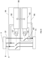
- Figure 6 shows an EVSE device 60 embodying the present invention.
- the EVSE device 60 contains a current sensor 40, and a single-pole earth contactor 54. In the embodiment of Figure 6 these components are all included within an outer housing of the EVSE device 60.
- the control unit 50' of the EVSE device 60 may be voltage-dependent, receiving a supply from the mains supply 3, or it could be voltage-independent (e.g., being battery powered). It may be entirely analogue or may include digital logic such as one or more microcontrollers or ASICs.
- the control unit 50' and earth contactor 54 together constitute earth-wire disconnection means as disclosed above.
- the control unit 50' In the event that the current in the earth wire 10 exceeds a preset threshold, optionally for more than a preset threshold period of time, this is detected by the control unit 50' based on current measurements obtained from the current sensor 40.
- the control unit 50' signals the double-pole live and neutral contactor 52' to open, so that the appliance is no longer supplied with power.
- the control unit 50' and live and neutral contactor 52' together constitute live-wire disconnection means as disclosed above.
- the control unit 50' also signals the earth contactor 54 to open, preferably a short delay after the live and neutral contactor 52' has opened.
- Figure 7 shows a variation of the embodiment of Figure 6 .
- the interlock mechanism 70 uses a double-pole earth contactor 54, one pole of which switches the earth wire 10, with the other pole being wired in series with the control line of the live and neutral contactor 52.
- the live and neutral contactor 52 can be closed only if the earth contactor 54 is already closed.
- the live and neutral wires 4, 8 can be connected to the vehicle 51 only when the earth wire 10 is already connected to the vehicle 51. This provides failsafe protection in case of a mechanical or electrical fault in the normal connection sequencing implemented by the controller 50'.
- Figure 8 shows a further variant embodiment in which the control unit 50' has a connection 80 to the live wire 4 and a connection 82 to the neutral wire 8. This provides power to the circuitry (e.g., processors etc.) in the control unit 50' and for operating the contactors 52', 54. Furthermore, the control unit 50' is connected to the earth wire 10 by a connection 84, downstream of the earth contactor 54 and the current sensor 40. This earth connection 84 can be used to earth the device 60, but also provides a reference to the control unit 50' for monitoring the supply to the vehicle 51. In this way, the power supply to the control unit 50' will never have an earth that is held at the live potential in the case of a broken PEN fault.
- connections 80, 82 preferably provide galvanic isolation of the control unit 50' from the supply 3-e.g., using a transformer, such as a transformer within an AC-to-DC power supply. Such isolation may be used in any of the embodiments disclosed herein that power the control unit from the main supply (rather than from a separate battery, for example).
- FIG 9 shows an alternative embodiment in which a protection device 96 embodying the invention is not integrated within an EVSE device (i.e. in the same housing), but is attached to an electrical supply system to which a separate EVSE 94 is also installed.
- the EVSE 94 includes a charging control unit 90, which in turn controls a live and neutral contactor 52', which controls the live and neutral supply to the vehicle 51.
- the separate protection device 96 includes a protection control unit 92.
- the protection control unit 92 when the current in the earth wire 10 exceeds a threshold value, the protection control unit 92 causes an earth contactor 54 to disconnect the earth wire 10 from the vehicle 51.
- the protection control unit 92 additionally transmits a signal 98 to the charging control unit 90, which causes the charging control unit 90 to open the live and neutral contactor 52' so that the live and the neutral wire are no longer connected to the vehicle 51.
- the signal 98 may be sent over a digital interface (e.g., USB) or over an analogue interface. In this way, the protection control unit 92 can also control the timing and order of the opening (and the closing) of the contactors 52', 54 as previously described.
- the protection device 96 is positioned between the EVSE 94 and the vehicle 51. However, it could alternatively be positioned between the EVSE 94 and the supply 3.
- Figure 10 shows a variation of the embodiment shown in Figure 9 .
- the protection control unit 92 provides a physical override device 100, instead of the electrical signalling between the protection device 96 and the EVSE 94.
- the override device 100 is physically installed within the EVSE 94 (e.g., during a retrofitting) but is controlled from the protection device 96. It is connected to the live and neutral contactor 52' in the EVSE 94 using auxiliary contactors, or mechanically linked contactors, for example a shunt trip.
- the protection control unit 92 transmits a signal to the override device 100, which can override the EVSE's control of the live and neutral contactor 52' to force the contactor 52' open.
- Override device 100 is configured to be able to override the charging control unit 90, which normally controls the charging switches, so that the switches of the live and neutral wires 4, 8 can be disconnected in case of a broken PEN fault, and cannot be reconnected until the override device 100 allows it.
- the protection control unit 92 may ensure that the live and neutral contactor 52' is opened before the earth contactor 54 is opened, and is closed only after the earth contactor 54 is closed.
- FIG 11 shows an alternative to the arrangement described with reference to Figure 10 .
- a separate external unit 110 which may be a DIN Rail component assembly, is installed between the supply 3 and the EVSE 94.
- the external unit 110 contains a double-pole miniature circuit breaker (MCB), connected to live and neutral, and a shunt trip 112 for tripping the MCB.
- the shunt trip 112 is controlled by leads extending from the protection control unit 92 of the protection device 96.
- the protection control unit 92 transmits a signal to the shunt trip 112 in the external unit 110, which isolates the live and neutral supplies.
- Such an embodiment may be attractive where it is undesirable or impossible to interface with an existing EVSE 94 as shown in Figure 9 , or to install an override device 100 as shown in Figure 10 , since it requires no additional connections to the EVSE 94.
- FIG 12 shows a standalone protection device 120 embodying the invention. This is electrically connected upstream of a conventional EVSE device 94 which is desired to be protected.
- This standalone protection device 120 provides a shunt trip 121 which can be used to control an existing miniature circuit breaker (MCB) or residual current device (RCD) to disconnect the live wire 4 and neutral wire 8 when the current sensor 40 detects current above a threshold level on the earth wire 10.
- MCB miniature circuit breaker
- RCD residual current device
- an external live and neutral contactor may be fitted alongside the standalone protection device 120.
- the disconnection conditions may be more complex than a simple threshold level-e.g., depending additionally or alternatively on a rate of change of current, or one or more other factors.
Landscapes
- Engineering & Computer Science (AREA)
- Power Engineering (AREA)
- Transportation (AREA)
- Mechanical Engineering (AREA)
- Life Sciences & Earth Sciences (AREA)
- Sustainable Development (AREA)
- Sustainable Energy (AREA)
- Emergency Protection Circuit Devices (AREA)
- Remote Monitoring And Control Of Power-Distribution Networks (AREA)
Claims (15)
- Elektrische Einrichtung, umfassend:einen Masseeingang (10a) zum Verbinden mit einem Massedraht (10) einer elektrischen Versorgung aus einem Verteilnetz;eine Masseschnittstelle zum Bereitstellen einer Masseverbindung vom Masseeingang (10a) zu einem Gerät (2');Stromerfassungsmittel (40) zum Erfassen eines Stromflusses durch den Masseeingang (10a);Massedraht-Trennmittel (48, 50', 54) zum Trennen der Masseschnittstelle vom Masseeingang (10a), wenn ein erfasster Stromfluss durch den Masseeingang eine Massedraht-Trennbedingung erfüllt; undPhasendraht-Trennmittel (42, 52') zum Einleiten einer Trennung eines Phasendrahts (4) der elektrischen Versorgung vom Gerät (2') vor oder gleichzeitig mit dem Trennen der Masseschnittstelle; unddadurch gekennzeichnet, dass sie weiter eine Verriegelung (70) umfasst zum Verhindern, dass der Phasendraht (4) mit dem Gerät (2') verbunden wird, wenn nicht die Masseschnittstelle bereits mit dem Masseeingang (10a) verbunden ist.
- Elektrische Einrichtung nach Anspruch 1, die einen Phasendrahtschalter (42) zum Verbinden des Phasendrahts (4) mit dem Gerät (2') umfasst, wobei die Verriegelung (70) einen Masseschalter (48) zwischen dem Masseeingang (10a) und der Masseschnittstelle umfasst, und wobei der Masseschalter (48) so eingerichtet ist, dass er ein Steuersignal zum Veranlassen des Schließens des Phasendrahtschalters (42) nur dann durchlässt, wenn der Masseschalter (48) geschlossen ist.
- Elektrische Einrichtung nach Anspruch 1 oder 2, wobei das Gerät (2') ein Elektrofahrzeug oder eine Elektrofahrzeug-Versorgungsausrüstung ist.
- Elektrische Einrichtung nach einem vorstehenden Anspruch, wobei die Massedraht-Trennbedingung erfordert, dass der erfasste Stromfluss eine vorbestimmte Schwelle überschreitet.
- Elektrische Einrichtung nach einem vorstehenden Anspruch, wobei das Phasendraht-Trennmittel (42, 52') so konfiguriert ist, dass es die Trennung des Phasendrahts (4) der elektrischen Versorgung als Reaktion auf das Bestimmen einleitet, dass der erfasste Stromfluss durch den Masseeingang die Massedraht-Trennbedingung erfüllt.
- Elektrische Einrichtung nach einem vorstehenden Anspruch, die so konfiguriert ist, dass sie die Trennung des Phasendrahts (4) einleitet, bevor sie die Masseschnittstelle (10a) vom Masseeingang (10a) trennt.
- Elektrische Einrichtung nach einem vorstehenden Anspruch, die Verbindungswiederherstellungsmittel zum Wiederherstellen der Verbindung der Masseschnittstelle zum Masseeingang (10a) und zum Einleiten der Wiederherstellung der Verbindung des Phasendrahts (4) zum Gerät umfasst, wobei das Verbindungswiederherstellungsmittel so konfiguriert ist, dass es die Verbindung der Masseschnittstelle zum Masseeingang (10a) wiederherstellt, bevor sie die Wiederherstellung der Verbindung des Phasendrahts zum Gerät (2') einleitet.
- Elektrische Einrichtung nach einem vorstehenden Anspruch, weiter umfassend:einen Phaseneingang (4a) zum Verbinden mit einem Phasendraht (4) der elektrischen Versorgung aus dem Verteilnetz; undeine Phasenschnittstelle zum Bereitstellen einer Phasenverbindung vom Phaseneingang (4a) zum Gerät (2'),wobei das Phasendraht-Trennmittel so konfiguriert ist, dass es die Phasenschnittstelle vor oder gleichzeitig mit dem Trennen der Masseschnittstelle vom Masseeingang (10a) vom Phaseneingang (4a) trennt.
- Elektrische Einrichtung nach einem der Ansprüche 1 bis 7, wobei das Phasendraht-Trennmittel so konfiguriert ist, dass es ein analoges oder digitales Signal an eine separate Steuereinrichtung, die nicht Teil der elektrischen Einrichtung ist, überträgt, zum Anweisen der separaten Steuereinrichtung dazu, das Gerät (2') vom Phasendraht der elektrischen Versorgung zu trennen.
- Elektrische Einrichtung nach einem der Ansprüche 1 bis 7, wobei das Phasendraht-Trennmittel (42, 52') einen mechanischen Aktor zum Betätigen von Schaltmitteln, die nicht Teil der elektrischen Einrichtung sind, zum Trennen des Phasendrahts (4) von der elektrischen Versorgung umfasst.
- Elektrische Einrichtung nach einem vorstehenden Anspruch, wobei das Massedraht-Trennmittel ein(en) elektrisch betätigtes/n Schütz, Aktor oder Relais umfasst.
- Elektrische Einrichtung nach einem vorstehenden Anspruch, wobei das Massedraht-Trennmittel (48, 50', 54) und das Phasendraht-Trennmittel (42, 52') Steuerschaltungen umfassen, die so konfiguriert sind, dass sie ein Signal von den Stromerfassungsmitteln empfangen und bestimmen, wann der erfasste Strom die Massedraht-Trennbedingung erfüllt.
- Elektrische Einrichtung nach einem vorstehenden Anspruch, die so konfiguriert ist, dass sie ein optisches oder akustisches Signal ausgibt, wenn die Massedraht-Trennbedingung erfüllt ist.
- Elektrische Einrichtung nach einem vorstehenden Anspruch, die zum Verbinden mit dem Massedraht eines Schutzmasse- und Neutral- (PEN-) Leiters einer elektrischen TN-C-S-Versorgung konfiguriert ist.
- Verfahren zum Steuern einer elektrischen Versorgung eines Geräts, umfassend:Erfassen eines Stromflusses durch einen Masseleiter (10b), der zwischen einen Massedraht (10) einer elektrischen Versorgung aus einem Verteilnetz und ein Gerät (2') geschaltet ist;Bestimmen, dass der erfasste Stromfluss eine Massedraht-Trennbedingung erfüllt, und als Reaktion darauf Trennen des Geräts vom Massedraht (10) der elektrischen Versorgung; undTrennen des Geräts (2') von einem Phasendraht (4) der elektrischen Versorgung vor oder gleichzeitig mit dem Trennen des Geräts (2') vom Massedraht (10); undgekennzeichnet durch das Verhindern, durch eine Verriegelung (70), dass das Gerät (2') mit dem Phasendraht (4) der elektrischen Versorgung verbunden wird, bis das Gerät (2') mit dem Massedraht (10) der elektrischen Versorgung verbunden wurde.
Applications Claiming Priority (2)
| Application Number | Priority Date | Filing Date | Title |
|---|---|---|---|
| GB1902740.8A GB2577354B (en) | 2019-02-28 | 2019-02-28 | Controlling an electrical supply to an appliance |
| PCT/GB2020/050387 WO2020174217A1 (en) | 2019-02-28 | 2020-02-19 | Controlling an electrical supply to an appliance |
Publications (3)
| Publication Number | Publication Date |
|---|---|
| EP3931928A1 EP3931928A1 (de) | 2022-01-05 |
| EP3931928C0 EP3931928C0 (de) | 2024-03-27 |
| EP3931928B1 true EP3931928B1 (de) | 2024-03-27 |
Family
ID=66377385
Family Applications (1)
| Application Number | Title | Priority Date | Filing Date |
|---|---|---|---|
| EP20708560.6A Active EP3931928B1 (de) | 2019-02-28 | 2020-02-19 | Steuerung einer elektrischen versorgung an ein gerät |
Country Status (7)
| Country | Link |
|---|---|
| US (1) | US20220134895A1 (de) |
| EP (1) | EP3931928B1 (de) |
| AU (1) | AU2020227258B2 (de) |
| CA (1) | CA3128627A1 (de) |
| ES (1) | ES2977162T3 (de) |
| GB (2) | GB2577354B (de) |
| WO (1) | WO2020174217A1 (de) |
Families Citing this family (6)
| Publication number | Priority date | Publication date | Assignee | Title |
|---|---|---|---|---|
| GB2603191B (en) * | 2021-02-01 | 2023-05-24 | Yunex Ltd | Open-neutral electrical fault isolator |
| GB2610847B (en) | 2021-09-17 | 2026-04-22 | Easee As | Earth terminal solution for an electrical apparatus |
| DE102022200477A1 (de) * | 2022-01-18 | 2023-07-20 | Siemens Energy Global GmbH & Co. KG | Überwachungseinrichtung für ein Stromnetz, Stromnetz sowie Verfahren zum Überwachen eines Stromnetzes |
| GB2623530A (en) * | 2022-10-18 | 2024-04-24 | Juuce Ltd | Fault detection module for an electrical supply system |
| GB2640919A (en) * | 2024-05-09 | 2025-11-12 | Greentec International Ltd | Diverted neutral current detector, apparatus, and method |
| DE102024130878A1 (de) | 2024-10-23 | 2026-04-23 | Bender Gmbh & Co. Kg | Verfahren und Vorrichtungen zum Prüfen und Überwachen der Durchgängigkeit eines PEN-Leiters für ein dreiphasiges TN-C-S-Stromversorgungssystem |
Family Cites Families (8)
| Publication number | Priority date | Publication date | Assignee | Title |
|---|---|---|---|---|
| US2637843A (en) * | 1950-02-07 | 1953-05-05 | Harold L Kammerdiener | Ground detector and protective system |
| DE19618279A1 (de) * | 1996-05-07 | 1997-11-13 | Kopp Heinrich Ag | DI-Schutzschalteinrichtung |
| DE19651718C2 (de) * | 1996-12-12 | 1998-10-29 | Kopp Heinrich Ag | Fehlerstromschutzeinrichtung |
| GB2373112B (en) | 2002-03-20 | 2003-03-05 | Roger Thomas Ronald Pilling | Method and apparatus for protecting against hazardous voltages on electrical installations |
| US8335062B2 (en) * | 2010-03-08 | 2012-12-18 | Pass & Seymour, Inc. | Protective device for an electrical supply facility |
| US8964339B2 (en) * | 2012-03-30 | 2015-02-24 | Yazaki North America, Inc. | Faulty protective earth ground circuit detection system and method |
| GB2506185A (en) * | 2012-09-25 | 2014-03-26 | Nissan Motor Mfg Uk Ltd | Fault detection system for electric vehicle charging |
| CN204391681U (zh) * | 2015-01-30 | 2015-06-10 | 赵春光 | 漏电保护器 |
-
2019
- 2019-02-28 GB GB1902740.8A patent/GB2577354B/en active Active
-
2020
- 2020-02-19 CA CA3128627A patent/CA3128627A1/en active Pending
- 2020-02-19 US US17/434,922 patent/US20220134895A1/en not_active Abandoned
- 2020-02-19 GB GB2104856.6A patent/GB2589812B/en active Active
- 2020-02-19 ES ES20708560T patent/ES2977162T3/es active Active
- 2020-02-19 WO PCT/GB2020/050387 patent/WO2020174217A1/en not_active Ceased
- 2020-02-19 EP EP20708560.6A patent/EP3931928B1/de active Active
- 2020-02-19 AU AU2020227258A patent/AU2020227258B2/en active Active
Also Published As
| Publication number | Publication date |
|---|---|
| GB202104856D0 (en) | 2021-05-19 |
| WO2020174217A1 (en) | 2020-09-03 |
| GB2589812A (en) | 2021-06-09 |
| GB2589812B (en) | 2021-12-15 |
| ES2977162T3 (es) | 2024-08-20 |
| AU2020227258B2 (en) | 2025-02-27 |
| AU2020227258A1 (en) | 2021-10-14 |
| GB2577354B (en) | 2020-11-11 |
| GB2577354A (en) | 2020-03-25 |
| EP3931928C0 (de) | 2024-03-27 |
| US20220134895A1 (en) | 2022-05-05 |
| CA3128627A1 (en) | 2020-09-03 |
| EP3931928A1 (de) | 2022-01-05 |
| GB201902740D0 (en) | 2019-04-17 |
Similar Documents
| Publication | Publication Date | Title |
|---|---|---|
| EP3931928B1 (de) | Steuerung einer elektrischen versorgung an ein gerät | |
| US8405939B2 (en) | Protective device for an electrical supply facility | |
| US8335062B2 (en) | Protective device for an electrical supply facility | |
| US9948087B2 (en) | Protective device for an electrical supply facility | |
| US8289664B2 (en) | Protective device for an electrical supply facility | |
| US9226414B2 (en) | Protective electrical device | |
| US8120883B2 (en) | Protective device with improved surge protection | |
| US7298598B1 (en) | Wiring device with multi-shot miswire | |
| US9819177B2 (en) | Protective device with non-volatile memory miswire circuit | |
| WO2016105551A1 (en) | Apparatus, system and method for total protection from electrical faults | |
| US11257649B2 (en) | Voltage protective device having a resettable circuit interrupter that is trippable in an overvoltage condition | |
| TWI542113B (zh) | 系統保護裝置、電路切換裝置、及電力供給系統 | |
| CN103138327B (zh) | 电动汽车的充电装置、充电系统和运行保护开关的方法 | |
| CN109073694A (zh) | 报警触发电源断开的装置、系统和方法 | |
| Brown | Electric vehicle supply equipment; a safety device | |
| JP7361315B2 (ja) | 電力中継装置、電源システム及び配電システム | |
| JP7308415B2 (ja) | 電力中継装置、電源システム及び配電システム | |
| CA2797411C (en) | Power-on reset gfci | |
| JP7620909B2 (ja) | 配電システム及び電源システム | |
| JP7336668B2 (ja) | 電力中継装置、電源システム及び配電システム | |
| GB2373112A (en) | Method and apparatus for protecting against hazardous voltages on electrical installations | |
| AU2008202541A1 (en) | An improved electronic earth leakage current device | |
| WO2015080569A1 (en) | An automatic power fault detection method and system for monitoring and controlling a power distribution system | |
| WO2021239852A1 (en) | Passive safety electrical system | |
| CN105027377A (zh) | 接地故障电流接口 |
Legal Events
| Date | Code | Title | Description |
|---|---|---|---|
| STAA | Information on the status of an ep patent application or granted ep patent |
Free format text: STATUS: UNKNOWN |
|
| STAA | Information on the status of an ep patent application or granted ep patent |
Free format text: STATUS: THE INTERNATIONAL PUBLICATION HAS BEEN MADE |
|
| PUAI | Public reference made under article 153(3) epc to a published international application that has entered the european phase |
Free format text: ORIGINAL CODE: 0009012 |
|
| STAA | Information on the status of an ep patent application or granted ep patent |
Free format text: STATUS: REQUEST FOR EXAMINATION WAS MADE |
|
| 17P | Request for examination filed |
Effective date: 20210927 |
|
| AK | Designated contracting states |
Kind code of ref document: A1 Designated state(s): AL AT BE BG CH CY CZ DE DK EE ES FI FR GB GR HR HU IE IS IT LI LT LU LV MC MK MT NL NO PL PT RO RS SE SI SK SM TR |
|
| RAP3 | Party data changed (applicant data changed or rights of an application transferred) |
Owner name: MYENERGI LTD |
|
| DAV | Request for validation of the european patent (deleted) | ||
| DAX | Request for extension of the european patent (deleted) | ||
| GRAP | Despatch of communication of intention to grant a patent |
Free format text: ORIGINAL CODE: EPIDOSNIGR1 |
|
| STAA | Information on the status of an ep patent application or granted ep patent |
Free format text: STATUS: GRANT OF PATENT IS INTENDED |
|
| RIC1 | Information provided on ipc code assigned before grant |
Ipc: B60L 53/62 20190101ALI20230908BHEP Ipc: B60L 3/12 20060101ALI20230908BHEP Ipc: B60L 3/04 20060101ALI20230908BHEP Ipc: B60L 3/00 20190101ALI20230908BHEP Ipc: H02H 3/16 20060101ALI20230908BHEP Ipc: H02H 3/14 20060101ALI20230908BHEP Ipc: H02H 5/10 20060101AFI20230908BHEP |
|
| INTG | Intention to grant announced |
Effective date: 20230929 |
|
| RBV | Designated contracting states (corrected) |
Designated state(s): AL AT BE BG CH CY CZ DE DK EE ES FI FR GR HR HU IE IS IT LI LT LU LV MC MK MT NL NO PL PT RO RS SE SI SK SM TR |
|
| GRAS | Grant fee paid |
Free format text: ORIGINAL CODE: EPIDOSNIGR3 |
|
| GRAA | (expected) grant |
Free format text: ORIGINAL CODE: 0009210 |
|
| STAA | Information on the status of an ep patent application or granted ep patent |
Free format text: STATUS: THE PATENT HAS BEEN GRANTED |
|
| RIN1 | Information on inventor provided before grant (corrected) |
Inventor name: RICHARD, ROBIN LOIC Inventor name: SUTTON, LEE ROBERT |
|
| AK | Designated contracting states |
Kind code of ref document: B1 Designated state(s): AL AT BE BG CH CY CZ DE DK EE ES FI FR GR HR HU IE IS IT LI LT LU LV MC MK MT NL NO PL PT RO RS SE SI SK SM TR |
|
| REG | Reference to a national code |
Ref country code: CH Ref legal event code: EP |
|
| REG | Reference to a national code |
Ref country code: DE Ref legal event code: R096 Ref document number: 602020027897 Country of ref document: DE |
|
| REG | Reference to a national code |
Ref country code: IE Ref legal event code: FG4D |
|
| U01 | Request for unitary effect filed |
Effective date: 20240327 |
|
| U07 | Unitary effect registered |
Designated state(s): AT BE BG DE DK EE FI FR IT LT LU LV MT NL PT SE SI Effective date: 20240408 |
|
| PG25 | Lapsed in a contracting state [announced via postgrant information from national office to epo] |
Ref country code: GR Free format text: LAPSE BECAUSE OF FAILURE TO SUBMIT A TRANSLATION OF THE DESCRIPTION OR TO PAY THE FEE WITHIN THE PRESCRIBED TIME-LIMIT Effective date: 20240628 |
|
| PG25 | Lapsed in a contracting state [announced via postgrant information from national office to epo] |
Ref country code: HR Free format text: LAPSE BECAUSE OF FAILURE TO SUBMIT A TRANSLATION OF THE DESCRIPTION OR TO PAY THE FEE WITHIN THE PRESCRIBED TIME-LIMIT Effective date: 20240327 Ref country code: RS Free format text: LAPSE BECAUSE OF FAILURE TO SUBMIT A TRANSLATION OF THE DESCRIPTION OR TO PAY THE FEE WITHIN THE PRESCRIBED TIME-LIMIT Effective date: 20240627 |
|
| PG25 | Lapsed in a contracting state [announced via postgrant information from national office to epo] |
Ref country code: RS Free format text: LAPSE BECAUSE OF FAILURE TO SUBMIT A TRANSLATION OF THE DESCRIPTION OR TO PAY THE FEE WITHIN THE PRESCRIBED TIME-LIMIT Effective date: 20240627 Ref country code: NO Free format text: LAPSE BECAUSE OF FAILURE TO SUBMIT A TRANSLATION OF THE DESCRIPTION OR TO PAY THE FEE WITHIN THE PRESCRIBED TIME-LIMIT Effective date: 20240627 Ref country code: HR Free format text: LAPSE BECAUSE OF FAILURE TO SUBMIT A TRANSLATION OF THE DESCRIPTION OR TO PAY THE FEE WITHIN THE PRESCRIBED TIME-LIMIT Effective date: 20240327 Ref country code: GR Free format text: LAPSE BECAUSE OF FAILURE TO SUBMIT A TRANSLATION OF THE DESCRIPTION OR TO PAY THE FEE WITHIN THE PRESCRIBED TIME-LIMIT Effective date: 20240628 |
|
| REG | Reference to a national code |
Ref country code: ES Ref legal event code: FG2A Ref document number: 2977162 Country of ref document: ES Kind code of ref document: T3 Effective date: 20240820 |
|
| PG25 | Lapsed in a contracting state [announced via postgrant information from national office to epo] |
Ref country code: IS Free format text: LAPSE BECAUSE OF FAILURE TO SUBMIT A TRANSLATION OF THE DESCRIPTION OR TO PAY THE FEE WITHIN THE PRESCRIBED TIME-LIMIT Effective date: 20240727 |
|
| PG25 | Lapsed in a contracting state [announced via postgrant information from national office to epo] |
Ref country code: SM Free format text: LAPSE BECAUSE OF FAILURE TO SUBMIT A TRANSLATION OF THE DESCRIPTION OR TO PAY THE FEE WITHIN THE PRESCRIBED TIME-LIMIT Effective date: 20240327 |
|
| PG25 | Lapsed in a contracting state [announced via postgrant information from national office to epo] |
Ref country code: CZ Free format text: LAPSE BECAUSE OF FAILURE TO SUBMIT A TRANSLATION OF THE DESCRIPTION OR TO PAY THE FEE WITHIN THE PRESCRIBED TIME-LIMIT Effective date: 20240327 |
|
| PG25 | Lapsed in a contracting state [announced via postgrant information from national office to epo] |
Ref country code: PL Free format text: LAPSE BECAUSE OF FAILURE TO SUBMIT A TRANSLATION OF THE DESCRIPTION OR TO PAY THE FEE WITHIN THE PRESCRIBED TIME-LIMIT Effective date: 20240327 |
|
| PG25 | Lapsed in a contracting state [announced via postgrant information from national office to epo] |
Ref country code: SK Free format text: LAPSE BECAUSE OF FAILURE TO SUBMIT A TRANSLATION OF THE DESCRIPTION OR TO PAY THE FEE WITHIN THE PRESCRIBED TIME-LIMIT Effective date: 20240327 |
|
| PG25 | Lapsed in a contracting state [announced via postgrant information from national office to epo] |
Ref country code: SM Free format text: LAPSE BECAUSE OF FAILURE TO SUBMIT A TRANSLATION OF THE DESCRIPTION OR TO PAY THE FEE WITHIN THE PRESCRIBED TIME-LIMIT Effective date: 20240327 Ref country code: SK Free format text: LAPSE BECAUSE OF FAILURE TO SUBMIT A TRANSLATION OF THE DESCRIPTION OR TO PAY THE FEE WITHIN THE PRESCRIBED TIME-LIMIT Effective date: 20240327 Ref country code: RO Free format text: LAPSE BECAUSE OF FAILURE TO SUBMIT A TRANSLATION OF THE DESCRIPTION OR TO PAY THE FEE WITHIN THE PRESCRIBED TIME-LIMIT Effective date: 20240327 Ref country code: PL Free format text: LAPSE BECAUSE OF FAILURE TO SUBMIT A TRANSLATION OF THE DESCRIPTION OR TO PAY THE FEE WITHIN THE PRESCRIBED TIME-LIMIT Effective date: 20240327 Ref country code: IS Free format text: LAPSE BECAUSE OF FAILURE TO SUBMIT A TRANSLATION OF THE DESCRIPTION OR TO PAY THE FEE WITHIN THE PRESCRIBED TIME-LIMIT Effective date: 20240727 Ref country code: CZ Free format text: LAPSE BECAUSE OF FAILURE TO SUBMIT A TRANSLATION OF THE DESCRIPTION OR TO PAY THE FEE WITHIN THE PRESCRIBED TIME-LIMIT Effective date: 20240327 |
|
| REG | Reference to a national code |
Ref country code: DE Ref legal event code: R097 Ref document number: 602020027897 Country of ref document: DE |
|
| PLBE | No opposition filed within time limit |
Free format text: ORIGINAL CODE: 0009261 |
|
| STAA | Information on the status of an ep patent application or granted ep patent |
Free format text: STATUS: NO OPPOSITION FILED WITHIN TIME LIMIT |
|
| 26N | No opposition filed |
Effective date: 20250103 |
|
| U20 | Renewal fee for the european patent with unitary effect paid |
Year of fee payment: 6 Effective date: 20250218 |
|
| PG25 | Lapsed in a contracting state [announced via postgrant information from national office to epo] |
Ref country code: MC Free format text: LAPSE BECAUSE OF FAILURE TO SUBMIT A TRANSLATION OF THE DESCRIPTION OR TO PAY THE FEE WITHIN THE PRESCRIBED TIME-LIMIT Effective date: 20240327 |
|
| REG | Reference to a national code |
Ref country code: CH Ref legal event code: PL |
|
| PG25 | Lapsed in a contracting state [announced via postgrant information from national office to epo] |
Ref country code: CH Free format text: LAPSE BECAUSE OF NON-PAYMENT OF DUE FEES Effective date: 20250228 |
|
| U20 | Renewal fee for the european patent with unitary effect paid |
Year of fee payment: 7 Effective date: 20260227 |
|
| PGFP | Annual fee paid to national office [announced via postgrant information from national office to epo] |
Ref country code: ES Payment date: 20260303 Year of fee payment: 7 |
|
| PGFP | Annual fee paid to national office [announced via postgrant information from national office to epo] |
Ref country code: IE Payment date: 20260218 Year of fee payment: 7 |