EP3931945B1 - Rotor pourvu d'un support de rotor en plusieurs pièces pour une machine électrique - Google Patents
Rotor pourvu d'un support de rotor en plusieurs pièces pour une machine électrique Download PDFInfo
- Publication number
- EP3931945B1 EP3931945B1 EP20706497.3A EP20706497A EP3931945B1 EP 3931945 B1 EP3931945 B1 EP 3931945B1 EP 20706497 A EP20706497 A EP 20706497A EP 3931945 B1 EP3931945 B1 EP 3931945B1
- Authority
- EP
- European Patent Office
- Prior art keywords
- rotor
- carrier
- axial
- carrier part
- radial
- Prior art date
- Legal status (The legal status is an assumption and is not a legal conclusion. Google has not performed a legal analysis and makes no representation as to the accuracy of the status listed.)
- Active
Links
Images



Classifications
-
- H—ELECTRICITY
- H02—GENERATION; CONVERSION OR DISTRIBUTION OF ELECTRIC POWER
- H02K—DYNAMO-ELECTRIC MACHINES
- H02K1/00—Details of the magnetic circuit
- H02K1/06—Details of the magnetic circuit characterised by the shape, form or construction
- H02K1/22—Rotating parts of the magnetic circuit
- H02K1/28—Means for mounting or fastening rotating magnetic parts on to, or to, the rotor structures
- H02K1/30—Means for mounting or fastening rotating magnetic parts on to, or to, the rotor structures using intermediate parts, e.g. spiders
Definitions
- the invention relates to a rotor for an electrical machine with a multi-part rotor carrier.
- a rotor which according to an application can be a component of an electric machine of an electric or hybrid vehicle, is for example provided with the DE 10 2007 032 131 A1
- the rotor carrier of the rotor comprises two carrier parts, namely a hollow cylindrical peripheral wall part and a disk-shaped base wall part attached to the end. Both carrier parts are firmly connected to one another by friction welding.
- the rotor carrier is intended for an electrical internal rotor machine, whereby a laminated core can be attached to the outer peripheral surface of the peripheral wall part in a manner not explained in more detail there.
- the rotor mentioned does have advantages in production due to its two-part design compared to cast rotor carriers and rotor carriers formed from solid material, i.e. one-piece rotor carriers.
- friction welding of the carrier parts requires complex pre-processing and, in order to achieve a particularly strong connection, a special design of the joining surfaces, which requires a certain minimum wall thickness of the carrier parts to be connected.
- tempering or annealing is required to reduce tension and final machining is required to comply with the required manufacturing tolerances.
- the invention based on the above-mentioned prior art, has the task of further improving a rotor of the type mentioned at the outset and, in particular, of producing a rotor carrier inexpensively and of having a simple design. Furthermore, the rotor carrier should be designed to ensure reliable fixation of a rotor lamination package.
- a rotor for an electrical machine is thus proposed with a multi-part rotor carrier and a laminated core arranged on the latter, the rotor carrier comprising a first carrier part with a cylinder section extending axially in relation to a rotational axis of the rotor for arranging the laminated core and a second carrier part with a radial section.
- the first carrier part is firmly connected to one another by means of the cylinder section and the second carrier part is firmly connected to one another by means of the radial section at a mutual connection area.
- the first carrier part and the second carrier part are in engagement by means of an axial plug connection, in particular by means of an axial plug-in toothing.
- the laminated core in order to reliably fix the laminated core, it is proposed to arrange the laminated core between a first axial stop provided on the first carrier part and a second axial stop formed on the second carrier part, wherein the first axial stop is formed by a radial section adjoining the cylinder section and wherein the second axial stop is formed by the radial section of the second carrier part and is arranged radially to the connection region.
- the first axial stop can be designed as an angled or bent section, particularly in relation to the cylinder section, and can extend radially over the entire laminated core if required.
- the stop can thus be designed in a radial position that is significantly different from the cylinder section and a joining surface of the laminated core.
- this usually falls in the Essentially, depending on the design of the electrical machine, it is associated with a radially inner or outer boundary of the laminated core.
- a laminated core is clamped radially on one side and, as a result, the radially opposite surface of the laminated core tends to fan out the individual laminations.
- the radial section in the proposed solution can extend well within the radial extent of the laminated core, in particular at least up to a third, up to half or even beyond, so that axial fanning out of the laminated core can be effectively avoided.
- the cylinder section formed on the first carrier part can be designed to form a rotor for an electric internal rotor machine with a radially outer joining surface, wherein the first and second axial stops are located radially outside the cylinder section and the connecting area of the carrier parts.
- these axial stops are arranged radially inward to a joining surface formed radially inward on the cylinder section, wherein no special measures are to be provided on the second carrier part due to the radial section already present there and usually running inwards, in particular for connection to a rotor shaft or rotor hub.
- the rotor according to the invention is characterized in that, in order to form the axial plug connection, axial tabs or teeth are provided which are spaced apart from one another in the circumferential direction on the end face of the first carrier part opposite the radial section, and recesses are provided between them, which are brought into engagement with corresponding openings on the second carrier part, and further that the first carrier part and the second carrier part are designed as sheet metal formed parts.
- an axial stop on the first and/or second carrier part has a contact area that protrudes from one of the radial sections to the laminated core, i.e. an axial projection.
- Such an axial projection thus has a smaller radial expansion. In this way, a reduction in the effective area on the laminated core and an increase in the axial contact pressure are generated, which leads to better cohesion of the laminated core, especially under temperature change loads and at high rotor speeds.
- Such an axial projection can be created, for example, by an intermediate element, by machining or by forming the carrier parts on their radial sections. In this way, an axial gap can be created on one or both end faces of the laminated core outside of these axial projections to the rotor carrier, which can extend radially inwards and/or outwards on the axial projection.
- such an axial projection on the rotor carrier can be closed in the circumferential direction or can be designed with an opening area.
- several axial projections can also be provided in the circumferential direction, which are separated from one another by gaps.
- the rotor laminated core thus only rests axially in certain areas at individual positions, in particular at points or in the form of a stamp on the rotor carrier.
- the gaps created in the radial direction and the aforementioned axial gaps can thus form cooling channels or cooling spaces through which air or a cooling fluid can flow to dissipate heat loss from the rotor laminated core.
- the rotor carrier of the proposed rotor can have radial passages which are connected to a spatial area adjacent to the laminated core and formed by the aforementioned radial and axial gaps.
- a cooling fluid can thus pass through the rotor carrier unhindered through these passages and absorb and dissipate waste heat through direct contact with the laminated core.
- the radial passages can advantageously be provided on the rotor carrier at a front end area of the laminated core or at any other position.
- first radial passages can be formed axially on the cylinder section of the first carrier part, approximately in the area of the first axial stop, and second radial passages can also be formed on the axially opposite side.
- the second radial passages can preferably be provided in the area of the axial side of the second carrier part facing the laminated core.
- the second radial passages can be formed at least partially by openings which, in the assembled state, remain between the two carrier parts in the area of the gaps in the toothing profile.
- the radial passages can be aligned with the gaps present in the area of the axial stops, in particular the radial gaps, so that an unhindered passage of a cooling fluid through the rotor carrier and laterally past the laminated core is thereby made possible.
- the axial projections explained and the gaps in the toothing profile on the rotor carrier are arranged offset from one another in the circumferential direction.
- the laminated core can be secured to the rotor carrier by a joint connection, for example by shrinking.
- a joint connection for example by shrinking.
- corresponding tooth-shaped and groove-shaped structures for example in the form of radial teeth or the like, can be formed on the cylinder section of the first carrier part and on the joining surface of the laminated core.
- axial channels can be provided radially between the rotor carrier and the laminated core, which are in fluid communication with the radial passages when a cooling fluid is present.
- the axial channels can in particular simultaneously be present or serve as elements of the aforementioned radial form-fitting connection between the rotor carrier and the laminated core.
- the radial form-fitting connection can be designed to be permeable in the axial direction for guiding a cooling fluid.
- a plurality of recesses, in particular grooves, distributed in the circumferential direction and extending axially can be formed on the joining surface of the laminated core, into which projections, in particular teeth, projecting radially on the cylinder section can engage.
- the projections on the first carrier part are not necessary for the projections on the first carrier part to be formed over the entire axial extent of the cylinder section. Rather, it is sufficient if a projection only extends over a fraction, in particular approximately between a quarter, a third or a half, of the axial extent of the cylinder section. Adjacent projections on the circumference of the rotor carrier can be arranged axially staggered on the cylinder section.
- the laminated core can comprise two partial packages, wherein at least some of the projections can overlap a mutual connection area of the partial packages. Other projections can engage on only one partial package at a time.
- annular segment space can be created between the joining surface of the first carrier part and the joining surface of the laminated core, through which a cooling fluid can also flow.
- the laminated core is only held on the rotor carrier in sections by the form-fitting connection.
- the carrier parts can be welded together with particular advantage.
- several welding areas can be provided, particularly in the area of the plug connection on the axial inside and/or outside. Welding can be carried out in certain areas, particularly at specific points and essentially sequentially, whereby the process heat introduced in the process essentially does not cause any distortion of the rotor. Subsequent tempering of the rotor and/or post-processing are not necessary.
- the invention further relates to an electrical machine with a rotor as described above and with a stator arranged radially to the rotor with a stator winding.
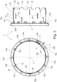
- Fig. 1 shows a rotor 1 for an electrical machine with a multi-part rotor carrier 2 and a laminated core 5 arranged on it.
- the rotor 1 is designed as a functional part of an electrical machine designed in an internal rotor construction, in particular a permanently excited synchronous machine, which is intended as a drive unit of a hybrid or electric vehicle.
- the electrical machine further comprises a stator (not shown in the drawing here) with a stator winding, which is arranged radially to the rotor 1 in the usual way, forming an air gap.
- the laminated core 5 of the rotor 1 is made in a known manner from axially stacked laminations and has pockets (not visible in the figures) in which permanent magnets are arranged.
- the rotor carrier 2 initially comprises a first carrier part 3 with a carrier part 4 which is axially extending cylinder section 3a for arranging the laminated core 5.
- a second carrier part 4 is provided, which initially comprises a radial section 4a.
- the carrier parts 3, 4 are formed from a comparatively thin-walled, but preferably high-strength steel sheet as sheet metal formed parts and, as will be explained in the course of the further description, are firmly connected to one another by means of the cylinder section 3a and by means of the radial section 4a at a mutual connection region 9.
- the laminated core 5 is received on a joining surface 3c of the cylinder section 3a and fixed between a first axial stop 6a provided on the first carrier part 3 and a second axial stop 6b formed on the second carrier part 4.
- the second axial stop 6b is formed by the radial section 4a and arranged radially to the connection region 9.
- both axial stops 6a, 6b are arranged radially outside the cylinder section 3a and the connection area 9.
- the first axial stop 6a is formed by a radial section 3b that is materially connected to the cylinder section 3a and angled there.
- the cylinder section 3a and the radial section 3b are formed in one piece. These stops are thus formed in a radial position that is significantly different from the cylinder section 3a or a joining surface 5a of the laminated core 5 located there.
- axial projections 10a; 10b are provided in the circumferential direction, which protrude axially towards the laminated core 5 relative to a base body of the radial sections 3b, 4a and which are in contact with the laminated core 5 and can exert an axial preload on it.
- the axial projections 10a; 10b are produced by forming the carrier parts, in particular by pressing out sheet metal material. In this way, axial and continuous radial gaps 14a, 14b on the laminated core 5 are produced outside of these axial projections 10a, 10b on both end faces of the laminated core to the rotor carrier 2. as in the Fig. 2 , 3 can be seen.
- the rotor laminated core 5 thus only rests axially at individual positions, in fact at points or in the form of a stamp on the rotor carrier 2.
- the axial projections 10a; 10b are arranged circumferentially in such a way that they preferably rest outside the magnet receiving pockets of the laminated core 5, in particular radially inside or between these magnet receiving pockets.
- the intermediate spaces 14a, b form radial channels 15a, b on the laminated core 5 in the radial direction, at least in sections or continuously, through which air or a cooling fluid can flow in order to dissipate heat loss from the rotor laminated core 5 and which, in the exemplary embodiment, have radial outlet openings. These outlet openings are located radially opposite the winding heads of a stator laminated core on the electrical machine. Alternatively, the outlet openings can also be formed axially.
- a plurality of axial extensions or teeth 18 spaced apart from one another in the circumferential direction and recesses or gaps 20 located between them in the manner of an axial toothing or an axial toothing profile are formed on the end face of the first carrier part 3 opposite the radial section 3b, i.e. on or adjacent to the cylinder section 3a.
- through-openings 22 are provided on the radial section 4a of the second carrier part 4, which correspond in their arrangement and dimensions to the teeth 18, engage with them and form a plug connection 23 with them, in particular in the manner of a plug-in toothing between the two carrier parts 3, 4.
- the rotor carrier 2 also has radial passages 26a; 26b, which are connected to the gaps 14a, 14b adjacent to the laminated core 5.
- a cooling fluid can thus pass unhindered through these passages 26a, 26b in the radial direction through the rotor carrier 2 and absorb and dissipate heat loss through the direct contact with the laminated core 5.
- the radial passages 26a, 26b are provided on the rotor carrier 2 at both end areas of the laminated core 5.
- the cylinder section 3a of the first carrier part 3 has axial passages approximately in the area of the first axial stop 6a, and second radial passages 26b are formed on the axially opposite side.
- the passages 26b are thus provided in the region of the axial side of the second carrier part 4 facing the laminated core 5.
- the passages 26b are formed by opening areas 20' which, in the assembled state, remain between the two carrier parts 3, 4 in the area of the recesses 20 of the toothed profile of the plug connection 23.
- the radial passages 26a, 26b are arranged in such a way that they are aligned with the gaps 14a, b present in the area of the axial projections 10a, 10b, in particular radially, so that an unhindered passage of a cooling fluid through the rotor carrier 2 and laterally on the laminated core 5 is thereby enabled.
- the axial projections 10a, 10b of the axial stops 6a, 6b are arranged offset from one another in the circumferential direction relative to the passages 26a, b and thus also to the recesses 20 of the tooth profile on the rotor carrier 2.
- arrows (F) The directions of propagation of a cooling fluid on the support parts 3 and 4 in radial and circumferential directions are indicated by arrows (F).
- a radial form-fitting connection 28 in particular in the form of a radial toothing, is formed between the first carrier part 3 and the laminated core 5.
- a projection 3d only extends over a part, in particular approximately between a third and a half of the axial extent of the cylinder section 3a.
- Neighboring projections 3d on the circumference of the rotor carrier 2 are also arranged axially staggered on the cylinder section 3a.
- the laminated core 5 comprises two partial packages 5b, 5c, with at least some of the projections 3d forming a mutual connection area of the Partial packages 5b, 5c overlap. Other projections 3d only engage with one partial package 5b, 5c.
- a plurality of axial channels 30 distributed around the circumference are provided radially between the rotor carrier 2 and the laminated core 5, which are in fluid communication with the radial passages 26a, 26b in the presence of a cooling fluid.
- the axial channels 30 are formed by the grooves 5d of the laminated core 5, i.e. by elements of the previously mentioned radial form-fitting connection 28.
- the form-fitting connection 28 can be designed to be permeable in the axial direction to guide a cooling fluid, for example by the interacting profiles of the rotor carrier 2 and the laminated core 5 not touching over their entire surface, but only abutting against one another in a point-like or linear manner and/or for example by the teeth or projections 3d on the cylinder section 3a being axially open on both sides and thus permeable.
- balancing areas 32a, b are provided on both carrier parts 3, 4, which are designed in particular as ring areas adjoining one of the radial sections 3b, 4a. Balancing weights and/or balancing openings can be attached or introduced into these balancing areas 32a, b when balancing the rotor 1.
- the rotor carrier 2 further comprises a rotor hub 34 with a hollow cylindrical shaft section 36 and with a radial flange 38 formed thereon, to which the second carrier part 4 is connected.
- the radial flange 38 has a centering surface 38a and an axial stop 38b.
- the second carrier part 4 is arranged on an axial end region of the first carrier part 3 and thus also on an axial end region of the rotor 1.
- the rotor 1 is designed for simple mounting by means of the second carrier part 4.
- the second carrier part 4 further has two angled regions 4d, 4e, with a further radial section 4b and a arranged tubular cylinder section 4c is provided. This can achieve further stiffening and an increase in the load-bearing capacity of the rotor 1.
- the laminated core 5 is pushed onto the carrier part 3 until it rests on the axial projections 10a.
- the carrier part 4 is inserted with its through-openings 22 onto the teeth 18 of the carrier part 3 until it rests on the axial projections 10b and is held there under a prestress by means of a contact force.
- the carrier parts 3, 4 are joined together, an adjustment in the radial direction and a compensation of length tolerances in the axial position can be carried out at the same time.
- the carrier parts 3, 4 are welded together in the area of the plug connection 23 on the axial inside and/or outside by means of several welding areas 24.
Landscapes
- Engineering & Computer Science (AREA)
- Power Engineering (AREA)
- Iron Core Of Rotating Electric Machines (AREA)
Claims (11)
- Rotor (1) pour une machine électrique avec un support de rotor (2) en plusieurs parties et un noyau feuilleté (5) agencé sur celui-ci, le support de rotor (2) comprenant- une première partie de support (3) avec une section cylindrique (3a) s'étendant axialement par rapport à un axe de rotation (A) du rotor (1) pour agencer le noyau feuilleté (5) et- une deuxième partie de support (4) avec une section radiale (4a),- la première partie de support (3), au moyen de la section cylindrique (3a), et la deuxième partie de support (4), au moyen de la section radiale (4a), étant reliées fixement l'une à l'autre au niveau d'une zone de liaison mutuelle (9),- la première partie de support (3) et la deuxième partie de support (4) étant en prise au moyen d'une liaison axiale enfichable (23),- le noyau feuilleté (5) étant fixé entre une première butée axiale (6a) prévue sur la première partie de support (3) et une deuxième butée axiale (6b) formée sur la deuxième partie de support (4),- la première butée axiale (6a) étant formée par une section radiale (3b) se raccordant à la section cylindrique (3a),- la deuxième butée axiale (6b) étant formée par la section radiale (4a) et étant agencée radialement par rapport à la zone de liaison (9),
caractérisé en ce que- la liaison axiale enfichable (23) est en particulier une denture axiale enfichable, en ce que- pour la réalisation de la liaison axiale enfichable 23), il est prévu, sur la face frontale de la première partie de support (3) opposée à la section radiale (3b), des pattes ou des dents axiales (18) espacées les unes des autres dans la direction circonférentielle et des évidements (20) se trouvant entre celles-ci, qui sont amenés en prise avec des ouvertures (22) correspondantes sur la deuxième partie de support (4), et en ce que- la première partie de support (3) et la deuxième partie de support (4) sont réalisées sous forme de parties en tôle déformée. - Rotor selon la revendication 1, caractérisé en ce que la section radiale (4a) s'étend radialement au-delà des ouvertures (22) et chevauche radialement la section cylindrique (3a).
- Rotor selon la revendication 1 ou la revendication 2, caractérisé en ce que le support de rotor (2) comprend un moyeu de rotor (34) qui est relié à la deuxième partie de support (4).
- Rotor selon la revendication 3, caractérisé en ce que le moyeu de rotor (34) présente une section d'arbre cylindrique creuse (36) et une bride radiale (38) formée sur celle-ci, à laquelle est reliée la deuxième partie de support (4).
- Rotor selon l'une des revendications 1 à 4, caractérisé en ce que les parties de support (3, 4) sont soudées entre elles.
- Rotor selon l'une des revendications 1 à 5, caractérisé en ce qu'une butée axiale (6a, 6b) présente une saillie axiale (10a ; 10b) faisant saillie par rapport à l'une des portions radiales (3b, 4a) vers le noyau feuilleté (5).
- Rotor selon la revendication 6, caractérisé en ce que plusieurs saillies axiales (10a ; 10b) sont prévues dans la direction circonférentielle, lesquelles sont séparées les unes des autres par des espaces intermédiaires (14a ; 14b).
- Rotor selon la revendication 7, caractérisé en ce que le support de rotor (2) présente des passages radiaux (26a ; 26b) qui sont reliés aux espaces intermédiaires (14a, b).
- Rotor selon l'une des revendications 1 à 8, caractérisé en ce qu'une liaison radiale par complémentarité de forme (28) est formée entre la première partie de support (3) et le noyau feuilleté (5).
- Rotor selon l'une des revendications 1 à 9, caractérisé en ce que des canaux axiaux (30) sont prévus radialement entre le support de rotor (2) et le noyau feuilleté (5), lesquels sont en communication fluidique avec les premiers et/ou les deuxièmes passages radiaux (26a, 26b) en présence d'un fluide de refroidissement.
- Machine électrique comprenant un stator avec un enroulement statorique et un rotor configuré selon l'une des revendications 1 à 10 et agencé radialement par rapport au stator.
Applications Claiming Priority (2)
| Application Number | Priority Date | Filing Date | Title |
|---|---|---|---|
| DE102019202563.3A DE102019202563A1 (de) | 2019-02-26 | 2019-02-26 | Rotor für eine elektrische Maschine mit einem mehrteiligen Rotorträger |
| PCT/EP2020/054645 WO2020173831A1 (fr) | 2019-02-26 | 2020-02-21 | Rotor pourvu d'un support de rotor en plusieurs pièces pour une machine électrique |
Publications (2)
| Publication Number | Publication Date |
|---|---|
| EP3931945A1 EP3931945A1 (fr) | 2022-01-05 |
| EP3931945B1 true EP3931945B1 (fr) | 2024-12-04 |
Family
ID=69646007
Family Applications (1)
| Application Number | Title | Priority Date | Filing Date |
|---|---|---|---|
| EP20706497.3A Active EP3931945B1 (fr) | 2019-02-26 | 2020-02-21 | Rotor pourvu d'un support de rotor en plusieurs pièces pour une machine électrique |
Country Status (3)
| Country | Link |
|---|---|
| EP (1) | EP3931945B1 (fr) |
| DE (1) | DE102019202563A1 (fr) |
| WO (1) | WO2020173831A1 (fr) |
Families Citing this family (3)
| Publication number | Priority date | Publication date | Assignee | Title |
|---|---|---|---|---|
| DE102021204575A1 (de) | 2021-05-06 | 2022-11-10 | Zf Friedrichshafen Ag | Rotoranordnung für eine elektrische Maschine |
| DE102022133515A1 (de) * | 2022-12-15 | 2024-06-20 | Valeo Powertrain Gmbh | Rotor für eine elektrische Maschine |
| DE102024108918A1 (de) * | 2024-03-28 | 2025-10-02 | Borgwarner Inc. | Rotor für einen Außenläufermotor |
Family Cites Families (14)
| Publication number | Priority date | Publication date | Assignee | Title |
|---|---|---|---|---|
| DE578782C (de) * | 1933-06-17 | Siemens Schuckertwerke Akt Ges | Laeufer fuer Asynchronmaschinen | |
| DE19702737A1 (de) * | 1997-01-27 | 1998-07-30 | Hilti Ag | Elektromotor |
| EP0909004B1 (fr) * | 1997-10-01 | 2004-08-04 | Denyo Co., Ltd | Rotor à aimants permanent et dispositif de refroidissement |
| DE19951026A1 (de) * | 1999-10-22 | 2001-04-26 | Volkswagen Ag | Verfahren zum Herstellen eines Rotors einer elektrischen Maschine und entsprechender Rotor |
| JP2003079101A (ja) * | 2001-06-21 | 2003-03-14 | Nissan Motor Co Ltd | 回転電機の冷却構造 |
| DE102007032131A1 (de) * | 2007-06-30 | 2009-01-02 | Robert Bosch Gmbh | Rotorträger für eine elektrische Maschine sowie Verfahren zu seiner Herstellung |
| DE102010022621A1 (de) * | 2010-06-04 | 2011-12-08 | Volkswagen Ag | Rotorwelle für ein elektrisches Aggregat |
| DE102011121042A1 (de) * | 2011-12-14 | 2012-06-21 | Daimler Ag | Kühlanordnung für eine elektrische Maschine |
| EP2806539A1 (fr) * | 2013-05-21 | 2014-11-26 | Siemens Aktiengesellschaft | Pièce active et rotor modulaire pour une machine électrique |
| JP2015027119A (ja) * | 2013-07-24 | 2015-02-05 | トヨタ自動車株式会社 | モータ用ロータ |
| JP6032178B2 (ja) * | 2013-11-05 | 2016-11-24 | トヨタ自動車株式会社 | 誘導電動機のロータ |
| DE102016204794A1 (de) * | 2016-03-23 | 2017-09-28 | Thyssenkrupp Ag | Rotorsegment einer elektrischen Maschine |
| DE102016215979A1 (de) * | 2016-08-25 | 2018-03-01 | Thyssenkrupp Ag | Gebaute Rotorwelle asymmetrischer Bauweise sowie Rotor und Verfahren zur Herstellung der gebauten Rotorwelle und des Rotors |
| DE102017115229B4 (de) * | 2017-07-07 | 2019-11-28 | Thyssenkrupp Ag | Verfahren zur Herstellung eines Rotors für einen Elektromotor und mit diesem Verfahren hergestellter Rotor |
-
2019
- 2019-02-26 DE DE102019202563.3A patent/DE102019202563A1/de not_active Withdrawn
-
2020
- 2020-02-21 EP EP20706497.3A patent/EP3931945B1/fr active Active
- 2020-02-21 WO PCT/EP2020/054645 patent/WO2020173831A1/fr not_active Ceased
Also Published As
| Publication number | Publication date |
|---|---|
| DE102019202563A1 (de) | 2020-08-27 |
| WO2020173831A1 (fr) | 2020-09-03 |
| EP3931945A1 (fr) | 2022-01-05 |
Similar Documents
| Publication | Publication Date | Title |
|---|---|---|
| EP3649724B1 (fr) | Procédé de réalisation d'un rotor destiné à un moteur électrique et rotor produit grâce à ce procédé | |
| DE102008004876B4 (de) | Elektrische Maschine | |
| DE10027246C1 (de) | Elektrische Maschine mit einer Kühleinrichtung | |
| EP2084806B1 (fr) | Moteur électrique et procédé de fabrication d'un moteur électrique pour un servomoteur automobile | |
| EP3084936B1 (fr) | Rotor a reluctance comprenant une tole de rotor avec un evidement servant a reduire les tensions | |
| EP3931945B1 (fr) | Rotor pourvu d'un support de rotor en plusieurs pièces pour une machine électrique | |
| DE102009047485A1 (de) | Elektrische Maschine | |
| WO2011009514A1 (fr) | Stator d'un véhicule hybride ou électrique, support de stator | |
| DE102018104653A1 (de) | Rotor, Asynchronmaschine und Verwendung einer Druckscheibe | |
| EP3130057A1 (fr) | Module comprenant un noyau feuilleté pour une machine électrique, procédé de fabrication d'un tel module et machine électrique | |
| DE102022004793A1 (de) | Befestigungsanordnung eines Blechpakets eines Stators an einem Gehäuse einer Axialflussmaschine, insbesondere für ein Kraftfahrzeug, Axialflussmaschine sowie Kraftfahrzeug | |
| EP1501170A1 (fr) | Moteur électrique avec fixation de stator | |
| EP1385252B1 (fr) | Machine électrique avec rotor extérieur et moyeu moulé | |
| WO2020016320A2 (fr) | Rotor pour un moteur électrique, procédé de fabrication d'un rotor et moteur électrique | |
| WO2008119660A2 (fr) | Rotor pour une machine électrodynamique | |
| DE102019202566A1 (de) | Rotor für eine elektrische Maschine mit Kühlkanälen | |
| DE102020210497A1 (de) | Rotor einer permanenterregten elektrischen Maschine | |
| WO2011009515A1 (fr) | Segment de stator et stator d'un véhicule hybride ou électrique | |
| DE102018104074A1 (de) | Rotor, Rotorwelle und elektrische Maschine | |
| WO2018197133A1 (fr) | Stator segmenté pour moteur électrique du type à rotor interne | |
| DE102015225582A1 (de) | Rotorlamellenpaket und Rotor für ein elektrisches Aggregat, insbesondere für einen Elektromotor, und Verfahren zur Herstellung eines solchen Rotors | |
| WO2021069537A1 (fr) | Stator d'une machine électrique | |
| DE102021209396A1 (de) | Rotor für einen Elektromotor | |
| DE102007060250A1 (de) | Anker für eine elektrische Maschine sowie Verfahren zur Herstellung eines Ankers | |
| DE102020214377A1 (de) | Rotorbaugruppe mit Spannlamelle |
Legal Events
| Date | Code | Title | Description |
|---|---|---|---|
| STAA | Information on the status of an ep patent application or granted ep patent |
Free format text: STATUS: UNKNOWN |
|
| STAA | Information on the status of an ep patent application or granted ep patent |
Free format text: STATUS: THE INTERNATIONAL PUBLICATION HAS BEEN MADE |
|
| PUAI | Public reference made under article 153(3) epc to a published international application that has entered the european phase |
Free format text: ORIGINAL CODE: 0009012 |
|
| STAA | Information on the status of an ep patent application or granted ep patent |
Free format text: STATUS: REQUEST FOR EXAMINATION WAS MADE |
|
| 17P | Request for examination filed |
Effective date: 20210825 |
|
| AK | Designated contracting states |
Kind code of ref document: A1 Designated state(s): AL AT BE BG CH CY CZ DE DK EE ES FI FR GB GR HR HU IE IS IT LI LT LU LV MC MK MT NL NO PL PT RO RS SE SI SK SM TR |
|
| DAV | Request for validation of the european patent (deleted) | ||
| DAX | Request for extension of the european patent (deleted) | ||
| GRAP | Despatch of communication of intention to grant a patent |
Free format text: ORIGINAL CODE: EPIDOSNIGR1 |
|
| STAA | Information on the status of an ep patent application or granted ep patent |
Free format text: STATUS: GRANT OF PATENT IS INTENDED |
|
| INTG | Intention to grant announced |
Effective date: 20240717 |
|
| GRAS | Grant fee paid |
Free format text: ORIGINAL CODE: EPIDOSNIGR3 |
|
| GRAA | (expected) grant |
Free format text: ORIGINAL CODE: 0009210 |
|
| STAA | Information on the status of an ep patent application or granted ep patent |
Free format text: STATUS: THE PATENT HAS BEEN GRANTED |
|
| AK | Designated contracting states |
Kind code of ref document: B1 Designated state(s): AL AT BE BG CH CY CZ DE DK EE ES FI FR GB GR HR HU IE IS IT LI LT LU LV MC MK MT NL NO PL PT RO RS SE SI SK SM TR |
|
| REG | Reference to a national code |
Ref country code: CH Ref legal event code: EP |
|
| REG | Reference to a national code |
Ref country code: DE Ref legal event code: R096 Ref document number: 502020009886 Country of ref document: DE |
|
| REG | Reference to a national code |
Ref country code: IE Ref legal event code: FG4D Free format text: LANGUAGE OF EP DOCUMENT: GERMAN |
|
| REG | Reference to a national code |
Ref country code: LT Ref legal event code: MG9D |
|
| REG | Reference to a national code |
Ref country code: NL Ref legal event code: MP Effective date: 20241204 |
|
| PG25 | Lapsed in a contracting state [announced via postgrant information from national office to epo] |
Ref country code: HR Free format text: LAPSE BECAUSE OF FAILURE TO SUBMIT A TRANSLATION OF THE DESCRIPTION OR TO PAY THE FEE WITHIN THE PRESCRIBED TIME-LIMIT Effective date: 20241204 |
|
| PG25 | Lapsed in a contracting state [announced via postgrant information from national office to epo] |
Ref country code: FI Free format text: LAPSE BECAUSE OF FAILURE TO SUBMIT A TRANSLATION OF THE DESCRIPTION OR TO PAY THE FEE WITHIN THE PRESCRIBED TIME-LIMIT Effective date: 20241204 |
|
| PG25 | Lapsed in a contracting state [announced via postgrant information from national office to epo] |
Ref country code: BG Free format text: LAPSE BECAUSE OF FAILURE TO SUBMIT A TRANSLATION OF THE DESCRIPTION OR TO PAY THE FEE WITHIN THE PRESCRIBED TIME-LIMIT Effective date: 20241204 |
|
| PG25 | Lapsed in a contracting state [announced via postgrant information from national office to epo] |
Ref country code: ES Free format text: LAPSE BECAUSE OF FAILURE TO SUBMIT A TRANSLATION OF THE DESCRIPTION OR TO PAY THE FEE WITHIN THE PRESCRIBED TIME-LIMIT Effective date: 20241204 |
|
| PG25 | Lapsed in a contracting state [announced via postgrant information from national office to epo] |
Ref country code: NO Free format text: LAPSE BECAUSE OF FAILURE TO SUBMIT A TRANSLATION OF THE DESCRIPTION OR TO PAY THE FEE WITHIN THE PRESCRIBED TIME-LIMIT Effective date: 20250304 |
|
| PG25 | Lapsed in a contracting state [announced via postgrant information from national office to epo] |
Ref country code: LV Free format text: LAPSE BECAUSE OF FAILURE TO SUBMIT A TRANSLATION OF THE DESCRIPTION OR TO PAY THE FEE WITHIN THE PRESCRIBED TIME-LIMIT Effective date: 20241204 Ref country code: GR Free format text: LAPSE BECAUSE OF FAILURE TO SUBMIT A TRANSLATION OF THE DESCRIPTION OR TO PAY THE FEE WITHIN THE PRESCRIBED TIME-LIMIT Effective date: 20250305 |
|
| PG25 | Lapsed in a contracting state [announced via postgrant information from national office to epo] |
Ref country code: RS Free format text: LAPSE BECAUSE OF FAILURE TO SUBMIT A TRANSLATION OF THE DESCRIPTION OR TO PAY THE FEE WITHIN THE PRESCRIBED TIME-LIMIT Effective date: 20250304 |
|
| PG25 | Lapsed in a contracting state [announced via postgrant information from national office to epo] |
Ref country code: NL Free format text: LAPSE BECAUSE OF FAILURE TO SUBMIT A TRANSLATION OF THE DESCRIPTION OR TO PAY THE FEE WITHIN THE PRESCRIBED TIME-LIMIT Effective date: 20241204 |
|
| PG25 | Lapsed in a contracting state [announced via postgrant information from national office to epo] |
Ref country code: SM Free format text: LAPSE BECAUSE OF FAILURE TO SUBMIT A TRANSLATION OF THE DESCRIPTION OR TO PAY THE FEE WITHIN THE PRESCRIBED TIME-LIMIT Effective date: 20241204 |
|
| PG25 | Lapsed in a contracting state [announced via postgrant information from national office to epo] |
Ref country code: PL Free format text: LAPSE BECAUSE OF FAILURE TO SUBMIT A TRANSLATION OF THE DESCRIPTION OR TO PAY THE FEE WITHIN THE PRESCRIBED TIME-LIMIT Effective date: 20241204 |
|
| PG25 | Lapsed in a contracting state [announced via postgrant information from national office to epo] |
Ref country code: IS Free format text: LAPSE BECAUSE OF FAILURE TO SUBMIT A TRANSLATION OF THE DESCRIPTION OR TO PAY THE FEE WITHIN THE PRESCRIBED TIME-LIMIT Effective date: 20250404 |
|
| PG25 | Lapsed in a contracting state [announced via postgrant information from national office to epo] |
Ref country code: PT Free format text: LAPSE BECAUSE OF FAILURE TO SUBMIT A TRANSLATION OF THE DESCRIPTION OR TO PAY THE FEE WITHIN THE PRESCRIBED TIME-LIMIT Effective date: 20250404 |
|
| PG25 | Lapsed in a contracting state [announced via postgrant information from national office to epo] |
Ref country code: EE Free format text: LAPSE BECAUSE OF FAILURE TO SUBMIT A TRANSLATION OF THE DESCRIPTION OR TO PAY THE FEE WITHIN THE PRESCRIBED TIME-LIMIT Effective date: 20241204 |
|
| PG25 | Lapsed in a contracting state [announced via postgrant information from national office to epo] |
Ref country code: RO Free format text: LAPSE BECAUSE OF FAILURE TO SUBMIT A TRANSLATION OF THE DESCRIPTION OR TO PAY THE FEE WITHIN THE PRESCRIBED TIME-LIMIT Effective date: 20241204 |
|
| PG25 | Lapsed in a contracting state [announced via postgrant information from national office to epo] |
Ref country code: SK Free format text: LAPSE BECAUSE OF FAILURE TO SUBMIT A TRANSLATION OF THE DESCRIPTION OR TO PAY THE FEE WITHIN THE PRESCRIBED TIME-LIMIT Effective date: 20241204 |
|
| PG25 | Lapsed in a contracting state [announced via postgrant information from national office to epo] |
Ref country code: CZ Free format text: LAPSE BECAUSE OF FAILURE TO SUBMIT A TRANSLATION OF THE DESCRIPTION OR TO PAY THE FEE WITHIN THE PRESCRIBED TIME-LIMIT Effective date: 20241204 |
|
| PG25 | Lapsed in a contracting state [announced via postgrant information from national office to epo] |
Ref country code: IT Free format text: LAPSE BECAUSE OF FAILURE TO SUBMIT A TRANSLATION OF THE DESCRIPTION OR TO PAY THE FEE WITHIN THE PRESCRIBED TIME-LIMIT Effective date: 20241204 |
|
| REG | Reference to a national code |
Ref country code: DE Ref legal event code: R097 Ref document number: 502020009886 Country of ref document: DE |
|
| PG25 | Lapsed in a contracting state [announced via postgrant information from national office to epo] |
Ref country code: SE Free format text: LAPSE BECAUSE OF FAILURE TO SUBMIT A TRANSLATION OF THE DESCRIPTION OR TO PAY THE FEE WITHIN THE PRESCRIBED TIME-LIMIT Effective date: 20241204 |
|
| PG25 | Lapsed in a contracting state [announced via postgrant information from national office to epo] |
Ref country code: MC Free format text: LAPSE BECAUSE OF FAILURE TO SUBMIT A TRANSLATION OF THE DESCRIPTION OR TO PAY THE FEE WITHIN THE PRESCRIBED TIME-LIMIT Effective date: 20241204 |
|
| REG | Reference to a national code |
Ref country code: CH Ref legal event code: PL |
|
| PG25 | Lapsed in a contracting state [announced via postgrant information from national office to epo] |
Ref country code: DK Free format text: LAPSE BECAUSE OF FAILURE TO SUBMIT A TRANSLATION OF THE DESCRIPTION OR TO PAY THE FEE WITHIN THE PRESCRIBED TIME-LIMIT Effective date: 20241204 |
|
| PLBE | No opposition filed within time limit |
Free format text: ORIGINAL CODE: 0009261 |
|
| STAA | Information on the status of an ep patent application or granted ep patent |
Free format text: STATUS: NO OPPOSITION FILED WITHIN TIME LIMIT |
|
| PG25 | Lapsed in a contracting state [announced via postgrant information from national office to epo] |
Ref country code: LU Free format text: LAPSE BECAUSE OF NON-PAYMENT OF DUE FEES Effective date: 20250221 |
|
| PG25 | Lapsed in a contracting state [announced via postgrant information from national office to epo] |
Ref country code: CH Free format text: LAPSE BECAUSE OF NON-PAYMENT OF DUE FEES Effective date: 20250228 |
|
| 26N | No opposition filed |
Effective date: 20250905 |
|
| GBPC | Gb: european patent ceased through non-payment of renewal fee |
Effective date: 20250304 |
|
| REG | Reference to a national code |
Ref country code: BE Ref legal event code: MM Effective date: 20250228 |
|
| PG25 | Lapsed in a contracting state [announced via postgrant information from national office to epo] |
Ref country code: GB Free format text: LAPSE BECAUSE OF NON-PAYMENT OF DUE FEES Effective date: 20250304 |
|
| PG25 | Lapsed in a contracting state [announced via postgrant information from national office to epo] |
Ref country code: FR Free format text: LAPSE BECAUSE OF NON-PAYMENT OF DUE FEES Effective date: 20250228 |
|
| PG25 | Lapsed in a contracting state [announced via postgrant information from national office to epo] |
Ref country code: BE Free format text: LAPSE BECAUSE OF NON-PAYMENT OF DUE FEES Effective date: 20250228 |
|
| PG25 | Lapsed in a contracting state [announced via postgrant information from national office to epo] |
Ref country code: IE Free format text: LAPSE BECAUSE OF NON-PAYMENT OF DUE FEES Effective date: 20250221 |
|
| PGFP | Annual fee paid to national office [announced via postgrant information from national office to epo] |
Ref country code: DE Payment date: 20251230 Year of fee payment: 7 |
|
| PG25 | Lapsed in a contracting state [announced via postgrant information from national office to epo] |
Ref country code: AT Free format text: LAPSE BECAUSE OF NON-PAYMENT OF DUE FEES Effective date: 20250221 |
|
| REG | Reference to a national code |
Ref country code: AT Ref legal event code: MM01 Ref document number: 1749202 Country of ref document: AT Kind code of ref document: T Effective date: 20250221 |