EP3932171B1 - Dispositif de séparation d'herbe - Google Patents
Dispositif de séparation d'herbe Download PDFInfo
- Publication number
- EP3932171B1 EP3932171B1 EP21183210.0A EP21183210A EP3932171B1 EP 3932171 B1 EP3932171 B1 EP 3932171B1 EP 21183210 A EP21183210 A EP 21183210A EP 3932171 B1 EP3932171 B1 EP 3932171B1
- Authority
- EP
- European Patent Office
- Prior art keywords
- rotation
- cutting plane
- discharge
- separation device
- guide element
- Prior art date
- Legal status (The legal status is an assumption and is not a legal conclusion. Google has not performed a legal analysis and makes no representation as to the accuracy of the status listed.)
- Active
Links
Images


Classifications
-
- A—HUMAN NECESSITIES
- A01—AGRICULTURE; FORESTRY; ANIMAL HUSBANDRY; HUNTING; TRAPPING; FISHING
- A01D—HARVESTING; MOWING
- A01D34/00—Mowers; Mowing apparatus of harvesters
- A01D34/835—Mowers; Mowing apparatus of harvesters specially adapted for particular purposes
-
- A—HUMAN NECESSITIES
- A01—AGRICULTURE; FORESTRY; ANIMAL HUSBANDRY; HUNTING; TRAPPING; FISHING
- A01D—HARVESTING; MOWING
- A01D33/00—Accessories for digging harvesters
- A01D33/06—Haulm-cutting mechanisms
-
- A—HUMAN NECESSITIES
- A01—AGRICULTURE; FORESTRY; ANIMAL HUSBANDRY; HUNTING; TRAPPING; FISHING
- A01D—HARVESTING; MOWING
- A01D34/00—Mowers; Mowing apparatus of harvesters
- A01D34/01—Mowers; Mowing apparatus of harvesters characterised by features relating to the type of cutting apparatus
- A01D34/412—Mowers; Mowing apparatus of harvesters characterised by features relating to the type of cutting apparatus having rotating cutters
- A01D34/63—Mowers; Mowing apparatus of harvesters characterised by features relating to the type of cutting apparatus having rotating cutters having cutters rotating about a vertical axis
- A01D34/64—Mowers; Mowing apparatus of harvesters characterised by features relating to the type of cutting apparatus having rotating cutters having cutters rotating about a vertical axis mounted on a vehicle, e.g. a tractor, or drawn by an animal or a vehicle
- A01D34/66—Mowers; Mowing apparatus of harvesters characterised by features relating to the type of cutting apparatus having rotating cutters having cutters rotating about a vertical axis mounted on a vehicle, e.g. a tractor, or drawn by an animal or a vehicle with two or more cutters
- A01D34/667—Means for directing the cut crop
Definitions
- the front guide element is preferably designed such that its distance from the plane of the rotation axis in the discharge direction increases at least in sections, in particular evenly.
- the advantage of this design is an adaptation of the discharge channel cross-section to the growing amount of weed to be conveyed along the discharge direction.
- the weed separating device has a separate blower, ie one not included in the rotation devices.
- This blower is designed in particular to accelerate the air flow in the discharge channel, alternatively or in addition to accelerating the air flow through the rotation devices. This allows higher flow speeds to be achieved in the discharge channel.
- the spiral guide element or its underside is essentially straight when cut through the axis of rotation.
- the feed channel is optically essentially placed on the cover element in order to facilitate the feeding of cut cabbage from below the cover element from the at least one separating element to the discharge channel.
- each rotation device is assigned a feed channel.
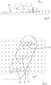
- the first embodiment of the herb separating device 2 according to the invention shown is designed for separating herb 4 from crops such as onions 6.
- the herb separating device 2 comprises a first rotation device 10 which is designed to rotate about a first rotation axis 20, a second rotation device 12 which is designed to rotate about a second rotation axis 22, and a third rotation device 14 which is designed to rotate about a third rotation axis 24.
- the rotation axes 20, 22, 24 are parallel to one another and in a rotation axis plane 60 arranged (cf. Fig.4 ).
- the rotation devices 10, 12, 14 are of identical construction and each have two separating elements 8 which, during operation, rotate in a cutting plane 26 orthogonal to the rotation axes 20, 22, 24.
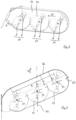
- the distance A of the overhead guide element 34 from the cutting plane 26 increases linearly with the extension of the discharge channel 30 in the discharge direction 32 (see in particular Figs. 8 and 9 ).
- the distance A increases continuously over a distance B which exceeds the distance between the rotation axes 20, 24 of the outermost rotation devices 10, 14.
- Each of the rotation devices 10, 12, 14 is assigned a rotation guide arrangement 42 which extends between the cover element 18 and the cutting plane 26 and beyond.
- the rotation guide arrangements 42 extend at a substantially constant distance from the respective rotation axis 20, 22, 24 by approximately 180° around the same.
- the rotation axis plane 60 is arranged at an angle of ⁇ 70° to a vertical longitudinal center plane 70 which is parallel to the direction of travel 72 (cf. Fig.7 ).
- the embodiments further comprise an adjustment device (not shown) which is designed to pivot the haulm separating device 2 relative to a machine frame (not shown) with which the haulm separating device 2 can be coupled to the tractor, from a first working position into a second working position.
- an adjustment device (not shown) which is designed to pivot the haulm separating device 2 relative to a machine frame (not shown) with which the haulm separating device 2 can be coupled to the tractor, from a first working position into a second working position.
- the angle between the rotation axis plane 60 and the longitudinal center plane 70 is changed by at least 7°.
Landscapes
- Life Sciences & Earth Sciences (AREA)
- Environmental Sciences (AREA)
- Harvester Elements (AREA)
- Apparatuses For Bulk Treatment Of Fruits And Vegetables And Apparatuses For Preparing Feeds (AREA)
- Soil Working Implements (AREA)
Claims (17)
- Dispositif de séparation de fanes (2) servant à la séparation de fanes (4) de plantes utiles telles que des oignons (6), lequel présente au moins un premier dispositif de rotation (10) qui est réalisé pour une rotation autour d'un premier axe de rotation (20) et au moins un élément de séparation (8) tournant, lors du fonctionnement, dans un plan de coupe (26) orthogonal au premier axe de rotation (20), présente au moins un deuxième dispositif de rotation (12) disposé de manière adjacente au premier dispositif de rotation (10), lequel deuxième dispositif de rotation est réalisé pour une rotation autour d'un deuxième axe de rotation (22) et présente au moins un élément de séparation (8) tournant lors du fonctionnement, et comprend un canal d'évacuation (30) s'étendant dans une direction d'évacuation (32) horizontale le long des axes de rotation (20, 22), lequel canal d'évacuation sert à l'évacuation des fanes (4), et est limité vers le haut par un élément de guidage supérieur (34), la distance (A) de l'élément de guidage supérieur (34) au plan de coupe (26) augmentant au moins dans certaines régions dans la direction d'évacuation (32) avec l'étendue du canal d'évacuation (30),
caractérisé en ce qu'un plan d'axes de rotation (60), dans lequel les axes de rotation (20, 22, 24) de tous les dispositifs de rotation (10, 12, 14) s'étendent, est disposé de manière inclinée de < 90° par rapport à un plan médian longitudinal (70) vertical et parallèle à la direction de conduite (72) lors du fonctionnement. - Dispositif de séparation de fanes selon la revendication 1, caractérisé en ce que la distance (A) de l'élément de guidage supérieur (34) au plan de coupe (26) augmente de manière ininterrompue au moins sur un trajet d'évacuation (B) qui correspond à la distance entre les axes de rotation (20, 24) des dispositifs de rotation (10, 14) les plus à l'extérieur.
- Dispositif de séparation de fanes selon l'une des revendications précédentes, caractérisé en ce que la distance (A) de l'élément de guidage supérieur (34) au plan de coupe (26) augmente de manière au moins sensiblement linéaire au moins dans certaines régions, en particulier sur tout le trajet d'évacuation (B).
- Dispositif de séparation de fanes selon l'une des revendications précédentes, caractérisé en ce qu'un côté inférieur de l'élément de guidage supérieur (34), considéré dans la direction d'évacuation (32), s'étend de manière rectiligne, en particulier parallèlement au plan de coupe (26), sur au moins la moitié d'une largeur (C), mesurée orthogonalement à la direction d'évacuation (32) et horizontalement, du canal d'évacuation (30).
- Dispositif de séparation de fanes selon l'une des revendications précédentes, caractérisé en ce que le canal d'évacuation (30) est limité, dans la direction de conduite, par un élément de guidage avant (36) dont la distance (D) à un plan d'axes de rotation (60), dans lequel se situent les axes de rotation (20, 22, 24) d'au moins deux des dispositifs de rotation (10, 12, 14), est au moins sensiblement constante.
- Dispositif de séparation de fanes selon l'une des revendications précédentes, caractérisé par au moins un élément de recouvrement (18) qui est disposé de telle sorte qu'il croise ou entoure au moins dans certaines régions au moins l'axe de rotation (20, 22, 24) d'un dispositif de rotation (10, 12, 14), en particulier les axes de rotation (20, 22, 24) de tous les dispositifs de rotation (10, 12, 14), et en ce qu'il a une plus faible distance au plan de coupe (26) qu'au moins une partie de l'élément de guidage supérieur (34).
- Dispositif de séparation de fanes selon la revendication 6, caractérisé en ce que la distance de la partie de l'élément de guidage supérieur (34) au plan de coupe (26) est supérieure d'au moins 200 mm, de préférence d'au moins 350 mm, de manière particulièrement préférée d'au moins 500 mm à la distance de l'élément de recouvrement (18) au plan de coupe (26).
- Dispositif de séparation de fanes selon la revendication 6 ou 7, caractérisé en ce que le canal d'évacuation (30), en particulier une partie de canal d'évacuation (38) espacée du plan de coupe (26) davantage que l'élément de recouvrement (18), a une largeur (C), mesurée orthogonalement à la direction d'évacuation (32) et parallèlement au plan de coupe (26), d'au moins 200 mm, de préférence d'au moins 250 mm, de manière particulièrement préférée d'au moins 300 mm.
- Dispositif de séparation de fanes selon l'une des revendications 6 à 8, caractérisé en ce que la largeur (C) du canal d'évacuation (30), en particulier de la partie de canal d'évacuation (38) espacée du plan de coupe (26) davantage que l'élément de recouvrement (18) et/ou sur tout le trajet d'évacuation (B), est au moins sensiblement constante au moins dans certaines régions.
- Dispositif de séparation de fanes selon l'une des revendications 6 à 9, caractérisé par un élément de guidage de liaison (40) disposé en particulier sur tout le trajet d'évacuation (B) entre l'élément de guidage supérieur (34) et l'élément de recouvrement (18) et formant le canal d'évacuation (30), lequel élément de guidage de liaison s'étend au moins dans certaines régions de manière inclinée de < 90°, de préférence entre 45° et 89°, de manière particulièrement préférée entre 70° et 85° par rapport à l'élément de recouvrement (18) et/ou au plan de coupe (26).
- Dispositif de séparation de fanes selon l'une des revendications 6 à 10, caractérisé en ce qu'un agencement de guidage de rotation (42) disposé entre l'élément de recouvrement (18) et le plan de coupe (26) et s'étendant à une distance au moins sensiblement constante de l'axe de rotation (20, 22, 24) du dispositif de rotation (10, 12, 14), en particulier sur au moins 180°, autour de l'axe de rotation (20, 22, 24) est associé à au moins l'un des dispositifs de rotation (10, 12, 14).
- Dispositif de séparation de fanes selon l'une des revendications précédentes, caractérisé en ce qu'un canal d'alimentation (44) débouchant dans le canal d'évacuation (30) est associé à au moins l'un des dispositifs de rotation (10, 12, 14), lequel canal d'alimentation est au moins formé par un élément de guidage en spirale (46) périphérique au moins en partie autour de l'axe de rotation (20, 22, 24) du dispositif de rotation (10, 12, 14), élément de guidage en spirale dont la distance (E) au plan de coupe (26) augmente au moins dans certaines régions vers le canal d'évacuation (30).
- Dispositif de séparation de fanes selon l'une des revendications précédentes, caractérisé par un canal de déviation (50) se raccordant au canal d'évacuation (30) et présentant une ouverture d'éjection (52), lequel canal de déviation est réalisé pour la déviation d'un flux de canal, de telle sorte qu'une direction d'éjection (54) horizontale est inclinée d'au moins 45°, de préférence d'au moins 55° par rapport à la direction d'évacuation (32) .
- Dispositif de séparation de fanes selon la revendication 13, caractérisé en ce que le canal de déviation (50) est au moins formé par au moins un élément de déviation (56) réglable en hauteur sur un côté opposé aux axes de rotation (20, 22, 24).
- Dispositif de séparation de fanes selon la revendication 13 ou 14, caractérisé en ce que le canal de déviation (50) est au moins formé par au moins un/l'élément de déviation (56) sur un/le côté opposé aux axes de rotation (20, 22, 24), lequel élément de déviation est disposé de manière mobile au moins en partie parallèlement au plan de coupe (26) et/ou de manière pivotante autour d'un axe de pivotement de déviation (74) incliné, en particulier perpendiculaire, par rapport au plan de coupe (26).
- Dispositif de séparation de fanes selon la revendication 15, caractérisé en ce que l'élément de déviation (56) est disposé de manière pivotante autour de l'axe de pivotement de déviation (74) perpendiculaire en particulier au moins sensiblement au plan de coupe (26) à partir d'une première position, dans laquelle l'élément de déviation s'étend de préférence à plat parallèlement à un plan médian longitudinal (70) parallèle à la direction de conduite (72), sur au moins 20° et/ou au plus 35° vers l'extérieur dans une deuxième position.
- Dispositif de séparation de fanes selon l'une des revendications précédentes, caractérisé par un dispositif de réglage qui est réalisé pour un pivotement du dispositif de séparation de fanes (2) par rapport à un bâti de machine à partir d'une première position de travail dans une deuxième position de travail, de telle sorte qu'en l'occurrence l'angle entre le plan d'axes de rotation (60) et le plan médian longitudinal (70) soit modifié en particulier d'au moins 7°.
Applications Claiming Priority (1)
| Application Number | Priority Date | Filing Date | Title |
|---|---|---|---|
| DE102020117685.6A DE102020117685A1 (de) | 2020-07-03 | 2020-07-03 | Krauttrennvorrichtung |
Publications (3)
| Publication Number | Publication Date |
|---|---|
| EP3932171A1 EP3932171A1 (fr) | 2022-01-05 |
| EP3932171C0 EP3932171C0 (fr) | 2024-06-12 |
| EP3932171B1 true EP3932171B1 (fr) | 2024-06-12 |
Family
ID=76744739
Family Applications (1)
| Application Number | Title | Priority Date | Filing Date |
|---|---|---|---|
| EP21183210.0A Active EP3932171B1 (fr) | 2020-07-03 | 2021-07-01 | Dispositif de séparation d'herbe |
Country Status (2)
| Country | Link |
|---|---|
| EP (1) | EP3932171B1 (fr) |
| DE (1) | DE102020117685A1 (fr) |
Family Cites Families (6)
| Publication number | Priority date | Publication date | Assignee | Title |
|---|---|---|---|---|
| ZA763546B (en) * | 1975-06-16 | 1977-05-25 | Preston Marsh | Rotary weeding apparatus |
| AT389031B (de) * | 1984-07-23 | 1989-10-10 | Allg Maschinenentwicklungs Ges | Maehwerk |
| GB2432503B (en) | 2005-11-23 | 2008-03-26 | Nicholson Machinery Ltd | Method and apparatus for topping vegetables |
| ES2321361B1 (es) * | 2006-09-28 | 2010-03-09 | Jose Serrat Alcay | Cortadora de hierba. |
| DE202010003067U1 (de) * | 2010-03-03 | 2010-05-20 | Kommunaltechnik Instandsetzung Und Fertigungs-Gmbh | Anbaugerät zur mechanischen Unkrautbeseitigung und Unkrautaufnahme |
| CN110402678B (zh) * | 2019-08-21 | 2022-01-25 | 中新科农(山东)生态农业有限公司 | 一种用于治理宜农荒地杂草的小型农业设备 |
-
2020
- 2020-07-03 DE DE102020117685.6A patent/DE102020117685A1/de active Pending
-
2021
- 2021-07-01 EP EP21183210.0A patent/EP3932171B1/fr active Active
Also Published As
| Publication number | Publication date |
|---|---|
| EP3932171C0 (fr) | 2024-06-12 |
| EP3932171A1 (fr) | 2022-01-05 |
| DE102020117685A1 (de) | 2022-01-05 |
Similar Documents
| Publication | Publication Date | Title |
|---|---|---|
| DE602006000326T2 (de) | Schwenkbares Streugerät | |
| EP0580026B1 (fr) | Faucheuse avec boîtier et avec canal arrière d'expectoration ayant un dispositif de guidage | |
| DE102011085977A1 (de) | Sieb für eine Reinigungseinrichtung eines Mähdreschers | |
| DE3850769T2 (de) | Verfahren und vorrichtung zum ernten von feldfrüchten durch abstreifen. | |
| DE1507195C3 (de) | Erntemaschine für stengeliges Halmgut, insbesondere Mais | |
| DE2749046C3 (de) | Verteuereinrichtung für Häcksler | |
| EP3932171B1 (fr) | Dispositif de séparation d'herbe | |
| DE19729938A1 (de) | Reinigungsverfahren einer Zuckerrohrerntemaschine sowie nach diesem Verfahren arbeitende Zuckerrohrerntemaschine | |
| DE2160818C2 (de) | Kreiselheuwerbungsmaschine | |
| DE3725712C2 (fr) | ||
| EP3570656B1 (fr) | Crible | |
| EP4324323A1 (fr) | Moissonneuse-batteuse automotrice dotée d'un système de capteur pour détecter la perte de grain | |
| EP3930485B1 (fr) | Separateur | |
| DE102006027343A1 (de) | Maschine zur Ernte stängelartiger Pflanzen mit einer seitlich verstellbaren Teilerspitze und einem damit gekoppelten Vordruckbügel | |
| DE8014119U1 (de) | Verteileinrichtung für Häcksler | |
| EP1504651B1 (fr) | Procédé et appareil pour actionner le hache-paille et le répartisseur d'une moissonneuse-batteuse | |
| EP1731013B1 (fr) | Carter de faucheuse de paillage | |
| EP3210461B1 (fr) | Procédé de fonctionnement d'un dispositif de nettoyage pour moissonneuse-batteuse | |
| AT527147B1 (de) | Schneidwerk für einen Mähdrescher | |
| DE69705198T2 (de) | Erntemaschine | |
| DE68904501T2 (de) | Maschine zum versetzen von auf dem boden liegendem pflanzengut. | |
| DE1942733A1 (de) | Erntemaschine | |
| DE102023004560B3 (de) | Trennvorrichtung, Trennverfahren und Erntemaschine | |
| EP0628246A2 (fr) | Dispositif de mélange et de dosage de fourrage pour bétail ou similaire | |
| DE102012100972A1 (de) | Erntevorrichtung |
Legal Events
| Date | Code | Title | Description |
|---|---|---|---|
| PUAI | Public reference made under article 153(3) epc to a published international application that has entered the european phase |
Free format text: ORIGINAL CODE: 0009012 |
|
| STAA | Information on the status of an ep patent application or granted ep patent |
Free format text: STATUS: THE APPLICATION HAS BEEN PUBLISHED |
|
| AK | Designated contracting states |
Kind code of ref document: A1 Designated state(s): AL AT BE BG CH CY CZ DE DK EE ES FI FR GB GR HR HU IE IS IT LI LT LU LV MC MK MT NL NO PL PT RO RS SE SI SK SM TR |
|
| B565 | Issuance of search results under rule 164(2) epc |
Effective date: 20211129 |
|
| STAA | Information on the status of an ep patent application or granted ep patent |
Free format text: STATUS: REQUEST FOR EXAMINATION WAS MADE |
|
| 17P | Request for examination filed |
Effective date: 20220224 |
|
| RBV | Designated contracting states (corrected) |
Designated state(s): AL AT BE BG CH CY CZ DE DK EE ES FI FR GB GR HR HU IE IS IT LI LT LU LV MC MK MT NL NO PL PT RO RS SE SI SK SM TR |
|
| GRAP | Despatch of communication of intention to grant a patent |
Free format text: ORIGINAL CODE: EPIDOSNIGR1 |
|
| STAA | Information on the status of an ep patent application or granted ep patent |
Free format text: STATUS: GRANT OF PATENT IS INTENDED |
|
| GRAJ | Information related to disapproval of communication of intention to grant by the applicant or resumption of examination proceedings by the epo deleted |
Free format text: ORIGINAL CODE: EPIDOSDIGR1 |
|
| STAA | Information on the status of an ep patent application or granted ep patent |
Free format text: STATUS: REQUEST FOR EXAMINATION WAS MADE |
|
| GRAP | Despatch of communication of intention to grant a patent |
Free format text: ORIGINAL CODE: EPIDOSNIGR1 |
|
| STAA | Information on the status of an ep patent application or granted ep patent |
Free format text: STATUS: GRANT OF PATENT IS INTENDED |
|
| INTG | Intention to grant announced |
Effective date: 20231211 |
|
| INTC | Intention to grant announced (deleted) | ||
| GRAS | Grant fee paid |
Free format text: ORIGINAL CODE: EPIDOSNIGR3 |
|
| INTG | Intention to grant announced |
Effective date: 20240109 |
|
| GRAA | (expected) grant |
Free format text: ORIGINAL CODE: 0009210 |
|
| STAA | Information on the status of an ep patent application or granted ep patent |
Free format text: STATUS: THE PATENT HAS BEEN GRANTED |
|
| AK | Designated contracting states |
Kind code of ref document: B1 Designated state(s): AL AT BE BG CH CY CZ DE DK EE ES FI FR GB GR HR HU IE IS IT LI LT LU LV MC MK MT NL NO PL PT RO RS SE SI SK SM TR |
|
| REG | Reference to a national code |
Ref country code: GB Ref legal event code: FG4D Free format text: NOT ENGLISH |
|
| REG | Reference to a national code |
Ref country code: CH Ref legal event code: EP |
|
| REG | Reference to a national code |
Ref country code: IE Ref legal event code: FG4D Free format text: LANGUAGE OF EP DOCUMENT: GERMAN |
|
| REG | Reference to a national code |
Ref country code: DE Ref legal event code: R096 Ref document number: 502021003970 Country of ref document: DE |
|
| U01 | Request for unitary effect filed |
Effective date: 20240612 |
|
| U07 | Unitary effect registered |
Designated state(s): AT BE BG DE DK EE FI FR IT LT LU LV MT NL PT SE SI Effective date: 20240620 |
|
| U20 | Renewal fee for the european patent with unitary effect paid |
Year of fee payment: 4 Effective date: 20240822 |
|
| PG25 | Lapsed in a contracting state [announced via postgrant information from national office to epo] |
Ref country code: HR Free format text: LAPSE BECAUSE OF FAILURE TO SUBMIT A TRANSLATION OF THE DESCRIPTION OR TO PAY THE FEE WITHIN THE PRESCRIBED TIME-LIMIT Effective date: 20240612 |
|
| PG25 | Lapsed in a contracting state [announced via postgrant information from national office to epo] |
Ref country code: GR Free format text: LAPSE BECAUSE OF FAILURE TO SUBMIT A TRANSLATION OF THE DESCRIPTION OR TO PAY THE FEE WITHIN THE PRESCRIBED TIME-LIMIT Effective date: 20240913 |
|
| PG25 | Lapsed in a contracting state [announced via postgrant information from national office to epo] |
Ref country code: ES Free format text: LAPSE BECAUSE OF FAILURE TO SUBMIT A TRANSLATION OF THE DESCRIPTION OR TO PAY THE FEE WITHIN THE PRESCRIBED TIME-LIMIT Effective date: 20240612 |
|
| PG25 | Lapsed in a contracting state [announced via postgrant information from national office to epo] |
Ref country code: NO Free format text: LAPSE BECAUSE OF FAILURE TO SUBMIT A TRANSLATION OF THE DESCRIPTION OR TO PAY THE FEE WITHIN THE PRESCRIBED TIME-LIMIT Effective date: 20240912 Ref country code: HR Free format text: LAPSE BECAUSE OF FAILURE TO SUBMIT A TRANSLATION OF THE DESCRIPTION OR TO PAY THE FEE WITHIN THE PRESCRIBED TIME-LIMIT Effective date: 20240612 Ref country code: GR Free format text: LAPSE BECAUSE OF FAILURE TO SUBMIT A TRANSLATION OF THE DESCRIPTION OR TO PAY THE FEE WITHIN THE PRESCRIBED TIME-LIMIT Effective date: 20240913 Ref country code: ES Free format text: LAPSE BECAUSE OF FAILURE TO SUBMIT A TRANSLATION OF THE DESCRIPTION OR TO PAY THE FEE WITHIN THE PRESCRIBED TIME-LIMIT Effective date: 20240612 Ref country code: RS Free format text: LAPSE BECAUSE OF FAILURE TO SUBMIT A TRANSLATION OF THE DESCRIPTION OR TO PAY THE FEE WITHIN THE PRESCRIBED TIME-LIMIT Effective date: 20240912 |
|
| PG25 | Lapsed in a contracting state [announced via postgrant information from national office to epo] |
Ref country code: PL Free format text: LAPSE BECAUSE OF FAILURE TO SUBMIT A TRANSLATION OF THE DESCRIPTION OR TO PAY THE FEE WITHIN THE PRESCRIBED TIME-LIMIT Effective date: 20240612 |
|
| PG25 | Lapsed in a contracting state [announced via postgrant information from national office to epo] |
Ref country code: IS Free format text: LAPSE BECAUSE OF FAILURE TO SUBMIT A TRANSLATION OF THE DESCRIPTION OR TO PAY THE FEE WITHIN THE PRESCRIBED TIME-LIMIT Effective date: 20241012 |
|
| PG25 | Lapsed in a contracting state [announced via postgrant information from national office to epo] |
Ref country code: CZ Free format text: LAPSE BECAUSE OF FAILURE TO SUBMIT A TRANSLATION OF THE DESCRIPTION OR TO PAY THE FEE WITHIN THE PRESCRIBED TIME-LIMIT Effective date: 20240612 |
|
| PG25 | Lapsed in a contracting state [announced via postgrant information from national office to epo] |
Ref country code: RO Free format text: LAPSE BECAUSE OF FAILURE TO SUBMIT A TRANSLATION OF THE DESCRIPTION OR TO PAY THE FEE WITHIN THE PRESCRIBED TIME-LIMIT Effective date: 20240612 Ref country code: SK Free format text: LAPSE BECAUSE OF FAILURE TO SUBMIT A TRANSLATION OF THE DESCRIPTION OR TO PAY THE FEE WITHIN THE PRESCRIBED TIME-LIMIT Effective date: 20240612 |
|
| PG25 | Lapsed in a contracting state [announced via postgrant information from national office to epo] |
Ref country code: SM Free format text: LAPSE BECAUSE OF FAILURE TO SUBMIT A TRANSLATION OF THE DESCRIPTION OR TO PAY THE FEE WITHIN THE PRESCRIBED TIME-LIMIT Effective date: 20240612 |
|
| PG25 | Lapsed in a contracting state [announced via postgrant information from national office to epo] |
Ref country code: SM Free format text: LAPSE BECAUSE OF FAILURE TO SUBMIT A TRANSLATION OF THE DESCRIPTION OR TO PAY THE FEE WITHIN THE PRESCRIBED TIME-LIMIT Effective date: 20240612 Ref country code: SK Free format text: LAPSE BECAUSE OF FAILURE TO SUBMIT A TRANSLATION OF THE DESCRIPTION OR TO PAY THE FEE WITHIN THE PRESCRIBED TIME-LIMIT Effective date: 20240612 Ref country code: RO Free format text: LAPSE BECAUSE OF FAILURE TO SUBMIT A TRANSLATION OF THE DESCRIPTION OR TO PAY THE FEE WITHIN THE PRESCRIBED TIME-LIMIT Effective date: 20240612 Ref country code: PL Free format text: LAPSE BECAUSE OF FAILURE TO SUBMIT A TRANSLATION OF THE DESCRIPTION OR TO PAY THE FEE WITHIN THE PRESCRIBED TIME-LIMIT Effective date: 20240612 Ref country code: IS Free format text: LAPSE BECAUSE OF FAILURE TO SUBMIT A TRANSLATION OF THE DESCRIPTION OR TO PAY THE FEE WITHIN THE PRESCRIBED TIME-LIMIT Effective date: 20241012 Ref country code: CZ Free format text: LAPSE BECAUSE OF FAILURE TO SUBMIT A TRANSLATION OF THE DESCRIPTION OR TO PAY THE FEE WITHIN THE PRESCRIBED TIME-LIMIT Effective date: 20240612 |
|
| REG | Reference to a national code |
Ref country code: CH Ref legal event code: PL |
|
| PG25 | Lapsed in a contracting state [announced via postgrant information from national office to epo] |
Ref country code: MC Free format text: LAPSE BECAUSE OF FAILURE TO SUBMIT A TRANSLATION OF THE DESCRIPTION OR TO PAY THE FEE WITHIN THE PRESCRIBED TIME-LIMIT Effective date: 20240612 |
|
| PG25 | Lapsed in a contracting state [announced via postgrant information from national office to epo] |
Ref country code: MC Free format text: LAPSE BECAUSE OF FAILURE TO SUBMIT A TRANSLATION OF THE DESCRIPTION OR TO PAY THE FEE WITHIN THE PRESCRIBED TIME-LIMIT Effective date: 20240612 |
|
| PLBE | No opposition filed within time limit |
Free format text: ORIGINAL CODE: 0009261 |
|
| STAA | Information on the status of an ep patent application or granted ep patent |
Free format text: STATUS: NO OPPOSITION FILED WITHIN TIME LIMIT |
|
| PG25 | Lapsed in a contracting state [announced via postgrant information from national office to epo] |
Ref country code: CH Free format text: LAPSE BECAUSE OF NON-PAYMENT OF DUE FEES Effective date: 20240731 |
|
| 26N | No opposition filed |
Effective date: 20250313 |
|
| PG25 | Lapsed in a contracting state [announced via postgrant information from national office to epo] |
Ref country code: IE Free format text: LAPSE BECAUSE OF NON-PAYMENT OF DUE FEES Effective date: 20240701 |
|
| U20 | Renewal fee for the european patent with unitary effect paid |
Year of fee payment: 5 Effective date: 20250729 |
|
| PGFP | Annual fee paid to national office [announced via postgrant information from national office to epo] |
Ref country code: GB Payment date: 20250724 Year of fee payment: 5 |
|
| PG25 | Lapsed in a contracting state [announced via postgrant information from national office to epo] |
Ref country code: CY Free format text: LAPSE BECAUSE OF FAILURE TO SUBMIT A TRANSLATION OF THE DESCRIPTION OR TO PAY THE FEE WITHIN THE PRESCRIBED TIME-LIMIT; INVALID AB INITIO Effective date: 20210701 |
|
| U1H | Name or address of the proprietor changed after the registration of the unitary effect |
Owner name: GRIMME LANDMASCHINENFABRIK SE & CO. KG; DE |
|
| PG25 | Lapsed in a contracting state [announced via postgrant information from national office to epo] |
Ref country code: HU Free format text: LAPSE BECAUSE OF FAILURE TO SUBMIT A TRANSLATION OF THE DESCRIPTION OR TO PAY THE FEE WITHIN THE PRESCRIBED TIME-LIMIT; INVALID AB INITIO Effective date: 20210701 |