EP3932650A2 - Dispositif d'aide au montage, système et procédé de mise en place d'un manchon interne dans un récipient de liquide, utilisation du dispositif d'aide au montage - Google Patents
Dispositif d'aide au montage, système et procédé de mise en place d'un manchon interne dans un récipient de liquide, utilisation du dispositif d'aide au montage Download PDFInfo
- Publication number
- EP3932650A2 EP3932650A2 EP21180416.6A EP21180416A EP3932650A2 EP 3932650 A2 EP3932650 A2 EP 3932650A2 EP 21180416 A EP21180416 A EP 21180416A EP 3932650 A2 EP3932650 A2 EP 3932650A2
- Authority
- EP
- European Patent Office
- Prior art keywords
- guide tube
- inner component
- liquid container
- adapter
- component
- Prior art date
- Legal status (The legal status is an assumption and is not a legal conclusion. Google has not performed a legal analysis and makes no representation as to the accuracy of the status listed.)
- Granted
Links
Images


Classifications
-
- B—PERFORMING OPERATIONS; TRANSPORTING
- B65—CONVEYING; PACKING; STORING; HANDLING THIN OR FILAMENTARY MATERIAL
- B65D—CONTAINERS FOR STORAGE OR TRANSPORT OF ARTICLES OR MATERIALS, e.g. BAGS, BARRELS, BOTTLES, BOXES, CANS, CARTONS, CRATES, DRUMS, JARS, TANKS, HOPPERS, FORWARDING CONTAINERS; ACCESSORIES, CLOSURES, OR FITTINGS THEREFOR; PACKAGING ELEMENTS; PACKAGES
- B65D77/00—Packages formed by enclosing articles or materials in preformed containers, e.g. boxes, cartons, sacks or bags
- B65D77/04—Articles or materials enclosed in two or more containers disposed one within another
- B65D77/06—Liquids or semi-liquids or other materials or articles enclosed in flexible containers disposed within rigid containers
- B65D77/061—Liquids or semi-liquids or other materials or articles enclosed in flexible containers disposed within rigid containers the containers being mounted on a pallet
-
- B—PERFORMING OPERATIONS; TRANSPORTING
- B29—WORKING OF PLASTICS; WORKING OF SUBSTANCES IN A PLASTIC STATE IN GENERAL
- B29C—SHAPING OR JOINING OF PLASTICS; SHAPING OF MATERIAL IN A PLASTIC STATE, NOT OTHERWISE PROVIDED FOR; AFTER-TREATMENT OF THE SHAPED PRODUCTS, e.g. REPAIRING
- B29C63/00—Lining or sheathing, i.e. applying preformed layers or sheathings of plastics; Apparatus therefor
- B29C63/0004—Component parts, details or accessories; Auxiliary operations
-
- B—PERFORMING OPERATIONS; TRANSPORTING
- B29—WORKING OF PLASTICS; WORKING OF SUBSTANCES IN A PLASTIC STATE IN GENERAL
- B29C—SHAPING OR JOINING OF PLASTICS; SHAPING OF MATERIAL IN A PLASTIC STATE, NOT OTHERWISE PROVIDED FOR; AFTER-TREATMENT OF THE SHAPED PRODUCTS, e.g. REPAIRING
- B29C63/00—Lining or sheathing, i.e. applying preformed layers or sheathings of plastics; Apparatus therefor
- B29C63/26—Lining or sheathing of internal surfaces
-
- B—PERFORMING OPERATIONS; TRANSPORTING
- B65—CONVEYING; PACKING; STORING; HANDLING THIN OR FILAMENTARY MATERIAL
- B65D—CONTAINERS FOR STORAGE OR TRANSPORT OF ARTICLES OR MATERIALS, e.g. BAGS, BARRELS, BOTTLES, BOXES, CANS, CARTONS, CRATES, DRUMS, JARS, TANKS, HOPPERS, FORWARDING CONTAINERS; ACCESSORIES, CLOSURES, OR FITTINGS THEREFOR; PACKAGING ELEMENTS; PACKAGES
- B65D2588/00—Large container
- B65D2588/02—Large container rigid
- B65D2588/12—Large container rigid specially adapted for transport
- B65D2588/125—Intermediate bulk container [IBC]
Definitions
- the invention relates to an assembly aid device which is designed to support the assembly of an inner casing in an interior space of a liquid container.
- the invention also relates to a system comprising a liquid container which encloses an interior space, an inner casing which is designed for arrangement in the interior space of the liquid container, a vacuum source and such an assembly aid device.
- the invention further relates to a method for arranging an inner casing in an interior space of a liquid container and the use of an assembly aid device for arranging an inner casing in an interior space of a liquid container.
- IBCs Intermediate Bulk Containers
- An IBC is a container that is suitable for the transport and storage of liquid and free-flowing substances.
- Such containers are used for the storage and transport of products, intermediate or preliminary products, for example in the food, chemical, cosmetic and pharmaceutical industries. They are mainly used when medium quantities of a substance have to be transported or stored.
- An IBC is typically arranged on and attached to an industrial pallet. Usual capacities are between 300 l and 1,250 I. An IBC is therefore easy to handle and can be transported with an industrial truck, for example.
- the typical structure of an IBC consists of an outer lattice cage that encloses the actual liquid container, which in most cases is made of PE.
- the IBC usually has a screw socket on its upper side and preferably in the middle, which is closed with the aid of a screw cap.
- IBCs can be reused.
- the cleaning or reprocessing of an IBC is a manual process in which the container must be sprayed out and then rinsed out.
- the cleaning of the liquid container is time-consuming and labor-intensive and therefore represents a not inconsiderable cost factor.
- the success of the cleaning, the effort required during cleaning and the cleaning agents to be used depend on the type and degree of contamination. In some cases, even with great effort, high purity requirements can no longer be met, so that the area of application of the reprocessed IBC is limited.
- an assembly aid device which is set up to support the assembly of an inner casing in an interior space of a liquid container, comprising a guide tube extending in an axial direction, which is set up for attachment to a screw socket of the liquid container surrounding an opening, an inner component guided in the guide tube so as to be displaceable in the axial direction, wherein the inner component comprises a holder which is set up to detachably hold an adapter of the inner sheath surrounding an opening in the inner sheath and which, in the assembled state of the inner sheath, is set up to be attached to the screw socket, and wherein the inner assembly part has at least one suction channel which extends between a conveying end and a suction end, wherein the conveying end can be fluidly coupled to a negative pressure source and the suction end opens out in a section from the inner component that extends in a radial direction between an inside of the guide tube and un d of the holder, so that gas that is present can be sucked off with the vacuum source through the
- the assembly aid device makes it possible to arrange the inner shell in the interior of the liquid container without creases or almost without creases.
- the air which is located between the inside of the liquid container and the outside of the inner shell, is sucked out with the aid of the assembly aid device.
- the aid of the vacuum source which is, for example, a centrifugal compressor with a large delivery volume.
- the assembly aid device advantageously allows the inner casing to be arranged in the interior of the liquid container in a significantly shorter time. The assembly process can therefore be accelerated.
- the inner casing is introduced into the interior of the liquid container through this second opening and is connected airtight to the liquid container at a screw socket at this second opening, for example.
- the inner shell has, for example, a second suitable adapter, collar or the like.
- the (first) adapter of the inner shell is then pulled through the screw socket of the liquid container in the direction of the outer space and attached to the holder of the inner component.
- the guide tube of the assembly aid device is placed on the screw socket, for example screwed onto it.
- the connection between the guide tube of the assembly aid device and the screw socket of the liquid container is preferably fluid-tight, i.e. H. especially airtight.
- a suitable seal is provided on the guide tube, for example.
- the assembly aid device is developed in that the guide tube is set up for fluid-tight fastening on the screw socket. This sealing takes place, for example, by the seal already mentioned. Furthermore, it is provided in particular that a seal is present between the inner component and the guide tube which seals the inner component in a fluid-tight manner with respect to the guide tube.
- the inner component is sealed with respect to the guide tube, for example, with a sealing lip which rests against an inner wall of the guide tube along the circumference.
- an O-ring seal can be provided, which is arranged between an inner wall of the screw connection and an outer wall of the inner component, for example in a groove of the inner component.
- a flat seal, an O-ring seal or the like is provided to seal the guide tube against the screw socket.
- the guide tube extends between a first and a second end in an axial direction, the first end of the guide tube being provided to be placed on the screw socket of the liquid container.
- the guide tube is provided, for example, with an internal thread in the area of the first end.
- a length of the guide tube in the axial direction is also dimensioned such that the second end projects beyond an end face of the screw connection in the axial direction.
- the guide tube is therefore longer than the screw socket in the axial direction.
- the assembly aid device is developed in that the inner component is between a suction position and a sealing position (in the axial direction) is displaceably guided in the guide tube, the inner component in the suction position being arranged in a section of the guide tube which, when the guide tube is mounted on the screw socket, projects beyond an end face of the screw socket in the axial direction, and the inner component in the sealing position at a position in the guide tube is arranged in which the holder of the inner component brings the adapter of the inner shell with the screw socket, in particular a collar of the adapter with the end face of the screw socket in contact.
- the assembly aid device comprises a lock with which the inner component can be locked in the suction position with respect to the guide tube.
- the assembly aid device comprises a drive, for example an electromechanical or hydraulic drive, with which the inner component can be displaced between the suction position and the sealing position along the axial direction of the guide tube.
- a drive for example an electromechanical or hydraulic drive
- the inner component can be displaced between the suction position and the sealing position along the axial direction of the guide tube.
- an active drive is not required.
- the suction of the gas present between the outside of the inner shell and the inside of the liquid container creates a negative pressure in a region of the assembly aid device in which the suction end of the suction channel opens. This ensures that the atmospheric pressure, which acts on an upper side of the inner component, exerts an external force on the inner component that is directed in the direction of the screw socket of the liquid container.
- the lock is released, the inner component is displaced from the suction position into the sealing position along the axial direction, driven by the atmospheric pressure.
- the collar of the adapter of the inner shell is in contact with the end face of the screw socket, so that the inner shell is
- the holder of the inner component of the assembly aid device comprises a heating device which is set up to heat the adapter of the inner shell at least in sections.
- the heating device is, for example, a sealing tape which extends at least in sections in the circumferential direction of the holder, in particular extends completely along the circumference of the holder, and is set up to heat the collar of the adapter of the inner shell.
- the heating device i.e. the sealing tape used, for example, is set up to heat the collar of the adapter of the inner shell so much that it partially melts and is firmly bonded to the end face of the screw neck of the liquid container. In this way, the inner shell can be permanently connected / sealed to the liquid container.
- the heating device is mounted, for example, on an elastically deformable bearing.
- a band made of a heat-resistant expanded material for example made of silicone foam, is provided between the sealing band and the inner component.
- the assembly aid device is developed in that the inner component comprises an air inlet duct that enables air to enter a space enclosed by the inner shell, a filter being present which is set up so that from the surroundings into the Air flowing into the inner shell flows through the filter.
- the assembly aid device is further developed in that the inner component is a hollow cylindrical component, the outer jacket surface of which rests at least in sections on an inner side of the guide tube in order to guide the inner component in the guide tube in an axially displaceable manner, and the inner component in particular has an upper side and an opposite underside, with the suction channel opening out on the top side and the holder protruding as a protruding component with a reduced diameter on the underside, so that the inner component forms a circumferential step on the underside, and in particular the suction channel in an annular
- the area of the step of the inner component that is present on the underside opens out, which extends between the outer circumferential surface and the holder.
- the assembly aid device has proven to be particularly suitable in practice. It has also been found to be advantageous if, according to a further embodiment, the assembly aid device also includes the negative pressure source, for example a radial compressor or the like. In this way, a completely autonomous system can advantageously be provided, which does not depend on the provision of a vacuum supply on the part of an external vacuum source.
- the negative pressure source for example a radial compressor or the like.
- a system comprising a liquid container that encloses an interior space, an inner shell which is designed for arrangement in the interior of the liquid container, a vacuum source and an assembly aid device which is designed to facilitate the assembly of the inner shell in the interior space of the liquid container
- the assembly aid device comprises: a guide tube which extends in an axial direction and is designed to be fastened to a screw socket of the liquid container, and an inner component which is guided in the guide tube such that it can be displaced in an axial direction, the inner component comprising a holder which for this purpose is set up to detachably hold an adapter of the inner sheath surrounding an opening in the inner sheath, which adapter is set up in the assembled state of the inner sheath to be fastened to the screw socket, and wherein the inner component has at least one suction channel st, which extends between a conveying end and a suction end, wherein the conveying end communicates fluidically with the vacuum source and the suction end opens out in a section of
- the system is advantageously developed in that the guide tube is set up for fluid-tight fastening on the screw socket and a seal is present between the inner component and the guide tube which seals the inner component in a fluid-tight manner with respect to the guide tube.
- the system is developed in particular in that the inner component is guided in the guide tube such that it can be moved between a suction position and a sealing position, and the inner component is arranged in the suction position in a section of the guide tube which, when the guide tube is mounted on the screw socket, has a The end face of the screw socket protrudes in the axial direction, and the inner component is arranged in the sealing position at a position in the guide tube in which the holder of the inner component contacts the adapter of the inner shell with the screw socket, in particular a collar of the adapter with the end face of the screw socket brings.
- the system comprises an assembly aid device which is developed in that it comprises a locking device with which the inner component can be locked in the suction position relative to the guide tube.
- the holder of the inner component comprises a heating device which is set up to heat the adapter of the inner shell at least in sections so that the adapter can be connected, in particular welded, to the screw socket, so that in the sealing position the Adapter can be connected to the screw socket, the heating device is set up to heat a collar encompassed by the adapter of the inner casing and to connect it to an end face of the screw socket, the heating device in particular is designed as a sealing strip extending at least in sections in the circumferential direction, and wherein the heating device is mounted on an elastically deformable bearing in the axial direction, with a bearing made of a heat-resistant expanded material, in particular silicone foam, being present in particular between the sealing strip and the inner component.
- the liquid container in particular the screw socket of the liquid container, is made of a material with a higher melting point than the inner shell, in particular the adapter, and in particular a collar of the adapter of the inner shell.
- Such a configuration of the system advantageously allows the collar of the adapter of the inner sleeve, but not the material of the screw socket, to melt on the end face of the screw socket when the inner sleeve is sealed.
- the inner cover When the inner cover is later removed from the interior of the liquid container, the inner cover can be separated from the liquid container in the area of the collar of its adapter, for example by a cut along the circumference of the screw connection. The remaining part of the collar of the adapter of the inner shell can then be removed from the end face of the screw socket, for example cut off or peeled off.
- a liquid container can be provided for the subsequent use, which has an almost flat surface in the area of the end face of its screw socket, so that a collar of an adapter of a new inner shell can be reliably and efficiently connected to the end face.
- the method is further developed in that the inner component comprises an air inlet duct which enables air to enter a space enclosed by the inner shell from the surroundings, the assembly aid device comprising a filter which is set up in such a way that air flowing into the inner shell from the surroundings flows through the filter.
- the system is further developed in that the inner component is a hollow cylindrical component, the outer jacket surface of which rests at least in sections on an inner side of the guide tube in order to guide the inner component in the guide tube so that it can be displaced in the axial direction, and in particular the inner component has an upper side and comprises an opposite underside, with the suction channel opening out on the top side and the holder protruding as a protruding component with a reduced diameter on the underside, so that the inner component forms a circumferential step on the underside, and in particular the suction channel in an annular area
- the step of the inner component that is present on the underside opens out, which extends between the outer circumferential surface and the holder.
- the method is advantageously developed in that an assembly aid device is placed on the screw socket which comprises a locking device with which the inner component can be locked in the suction position relative to the guide tube. After a predetermined negative pressure has been reached in the suction channel, this locking is released, as a result of which the inner component is displaced from the suction position into the sealing position by the atmospheric pressure.
- an actuating device to be present for this purpose, with which the inner component of the assembly aid device is displaced between the suction position and the sealing position.
- the method is furthermore advantageously developed in that an assembly aid device is put on, in which the holder of the inner component comprises a heating device which is set up to heat the adapter of the inner shell at least in sections. After the sealing position has been reached, the heating device is activated and the adapter of the inner sleeve is connected to the Screw connection connected, in particular a collar of the adapter is connected to an end face of the screw connection.
- the object is achieved through the use of an assembly aid device according to one or more of the aforementioned embodiments for arranging the inner shell in the interior of the liquid container, the liquid container in particular being part of an IBC.
- Embodiments according to the invention can fulfill individual features or a combination of several features.
- features which are identified with “in particular” or “preferably” are to be understood as optional features.
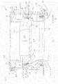
- Fig. 1 shows, in a schematically simplified cross-sectional view, an assembly aid device 2 which is placed on a screw connector 4 of a liquid container 6.
- the liquid container 6 is, for example, part of an IBC (Intermediate Bulk Container).
- the assembly aid device 2 comprises a guide tube 8 which extends in an axial direction A.
- an inner component 10 which is displaceable in the guide tube 8 in the axial direction A. is led.
- the screw socket 4 surrounds an opening 12 through which the liquid container 6 can be filled and, if necessary, also emptied.
- the guide tube 8 has an internal thread 14 at its lower or first end, with which the guide tube 8 can be screwed onto an external thread of the screw connector 4 so that the guide tube 8 can be fastened to the liquid container 6.
- the screw connection between the screw connector 4 and the guide tube 8 is designed in such a way that the guide tube 8 can be connected to the screw connector 4 in a fluid-tight manner, in particular airtight. For this purpose, if necessary, a seal not shown in the drawing is available.
- the guide tube 8 is designed, for example, as a hollow cylindrical component and is also made, for example, of polyethylene (PE).
- the inner component 10 can also be made of polyethylene.
- the inner component 10 is mounted displaceably in the axial direction A in the guide tube 8, in which outer guide surfaces 16 of the inner component 10, which are in the form of cylinder jacket surfaces, slide on an inside 18 of the guide tube 8.
- the inner component 10 is thus between the in Fig. 1 suction position shown and an in Fig. 3 Seal position shown, which will be described in more detail later, displaceable.
- the inner component 10 comprises a holder 20 which is configured to hold an adapter 22 of an inner shell 24.
- the holder 20 comprises one or more latching lugs 21, which in connection with Fig. 2 will be described in more detail.
- the entire lower region of the inner component 10 is to be regarded as the holder 20, namely that region of the inner component 10 which has a reduced diameter compared to the remaining part of the inner component 10 and protrudes from an underside 60 of the inner component 10.
- the inner shell 24 is designed to be arranged in an interior space 26 of the liquid container 6.
- the inner shell 24 includes an opening 28 which is surrounded by the adapter 22.
- the adapter 22 of the inner sleeve 24 is attached to the screw connector 4.
- a collar 30 of the adapter 22 of the inner shell 24 is welded to an end face 32 of the screw connector 4.
- the inner component 10 comprises at least one suction channel 34, preferably a plurality of suction channels 34, which extends between a conveying end 36 and a suction end 38.
- a suction channel 34 is described below only for reasons of better readability.
- the suction channel 34 passes through the inner component 10 and initially opens into a distribution chamber 40, which is also viewed as part of the suction channel 34. Starting from the distribution chamber 40, the suction channel 34 continues with an enlarged cross section. In the in Fig. 1 In the cross-sectional view shown, this part of the suction channel 34 is not visible and is therefore shown with a dashed line.
- the suction channel 34 ends at a conveying end 36 which opens out on an upper side 58 of the inner component 10.
- the suction channels 34 are dimensioned so that the sum of their cross sections (based on the sections opening into the suction ends 38 with a smaller cross section and the sections opening into the conveying ends 36 with a larger cross section) always remains constant. In this way, the flow rate within the suction channels 34 can be kept constant during the suction process. As a result of the cross-sectional expansion, fewer suction channels 34 can be provided which open out at the conveyor ends 36.
- the suction channels 34 are fluidic at the conveying ends 36 can be coupled to a vacuum source and have suitable connections for this purpose, for example.
- the suction ends 38 of the suction channels 34 open into a section of the inner component 10 which lies in a radial direction R between the inner side 18 of the guide tube 8 and the holder 20 with which the adapter 22 of the inner shell 24 is held. It is thus possible, via the at least one suction channel 34 between an outer side 42 of the inner shell 24 and an inner side 44 of the liquid container 6, to extract gas, in particular air, with the vacuum source.
- the inner component 10 is sealed in a fluid-tight manner with respect to the guide tube 8 as well as with respect to the screw connector 4.
- an O-ring-shaped seal can be arranged in a groove 46.
- a sealing lip is provided on the upper side 58 of the inner component 10, which rests against the inner wall 18 of the guide tube 8.
- the inner component 10 is secured by means of a lock 48, which is shown in FIG Fig. 1 is only shown in a greatly simplified and schematic manner, locked in the suction position shown in this figure with respect to the guide tube 8.
- a lock 48 which is shown in FIG Fig. 1 is only shown in a greatly simplified and schematic manner, locked in the suction position shown in this figure with respect to the guide tube 8.
- the more gas is pumped out of the space between the outer side 42 of the inner shell 24 and the inner side 44 of the liquid container 6, the further the inner shell 24 rests against the inner side 44 of the liquid container 6.
- This process continues until a negative pressure can be measured in the suction channel 34, which at least approximately corresponds to the negative pressure output of the negative pressure source.
- the atmospheric ambient pressure acts on the upper side 58 of the inner component 10.
- the lock 48 displaces the inner component 10 from the FIG Fig. 1 into the suction position shown in Fig. 3 Seal position shown.
- ambient air flows through a supply air duct 50 located centrally in the inner component 10 into the interior space 26 of the inner shell 24 be present through which the inflowing air indicated by the arrow flows.
- the degree of purity of the atmosphere can be adjusted by a suitable choice of the filter 52.
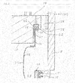
- Fig. 2 shows a schematically simplified detailed view of the in Fig. 1 shown cross-section.
- the holder 20 comprises, for example, one or more latching lugs 21, which can also be designed to be closed in the circumferential direction of the holder 20, that is to say form a circumferential latching lug 21 or the like.
- the adapter 22 comprises the collar 30, which extends inward to such an extent that it can be held by the latching lug 21.
- a heating device 54 is integrated into the inner component 10 above the collar 30 of the adapter 22.
- the heating device 54 is, for example, a sealing tape or another suitable heating device which is set up to heat the adapter 22 in the area of its collar 30 to such an extent that it melts at least to the extent that the adapter 22 of the inner shell 24 is in the area of the Collar 30 can be connected to the end face 32 of the screw connector 4.
- the heating device 54 is mounted on an elastic element 56 according to the illustrated embodiment.
- the elastic element 56 is, for example, a Tape made of a heat-resistant expanded material, for example around a tape made of silicone foam.
- Fig. 3 shows in a further schematically simplified cross-sectional view the assembly aid device 2 in the sealing position.
- the collar 30 of the adapter 22 of the inner shell 24 rests on the end face 32 of the screw socket 4 and the outer side 42 of the inner shell 24 rests against the inner side 44 of the liquid container 6.
- the heating device 54 can now be activated so that the collar 30 connects to the end face 32 of the screw connector 4.
- a material is selected for the adapter 22 of the inner shell 24 which has an at least slightly lower melting point than the material from which the liquid container 6, in particular the screw socket 4 of the liquid container 6, is made.
- the inner shell 24 can be cut open in the area of its adapter 22, in other words the melted part of the collar 30 of the adapter 22 can be removed from the end face 32 of the screw socket 4, for example peeled off.
- the liquid container 6 is now prepared so that a new inner shell 24 can be used.
- the inner component 10 of the assembly aid device is preferably designed as a hollow cylindrical component, the outer jacket surface of which at least in sections rests against the inside 18 of the guide tube 8 and provides the outer guide surfaces 16. So can the inner component 10 can be guided in the guide tube 8 such that it can be displaced in the axial direction A.
- the inner component 10 has an upper side 58 and an opposite, preferably plane-parallel oriented lower side 60.
- the at least one suction channel 34 opens out with its conveying end 36 at the upper side 58.
- the holder 20 is designed as a protruding component with a reduced diameter.
- the inner component 10 thus forms a step 62 running around in the circumferential direction on its underside 60.
- the suction channel 34 opens out in this annular region on the underside 60 of the inner component 10, that is to say in the region of the step 62 present there.
- This annular region of the step extends between the outer jacket surface 64 of the inner component 10 and the holder 20 of the inner component 10.
- Fig. 4 shows a schematically simplified side view of a system 70 which comprises a liquid container 6, an assembly aid device 2, an inner casing 24 (not visible in this illustration) and a vacuum source 72.
- the vacuum source 72 is, for example, a radial compressor with a high volume output. This is connected to the assembly aid device 2 via a vacuum line 74.
- the liquid container 6 is part of an IBC 76 which, in addition to the actual liquid container 6, also includes a lattice cage 78 in which the liquid container 6 is arranged, and a pallet 80.
- the pallet 80 is used to easily transport the IBC 76, for example with the aid of an industrial truck.
- Fig. 5 shows a schematically simplified front view of this system 70, the vacuum source 72 and the vacuum line 74 not being shown for the sake of simplifying the drawing.
- the liquid container 6 has an outlet connection 82 in a lower region, via which the liquid container 6 is preferred is emptied.
- the inner casing 24 is introduced into the liquid container 6, for example, via this outlet connection 82. It is also screwed in a fluid-tight manner in the area of the outlet connection 82, for example with the aid of an O-ring seal.
- the adapter 22 of the inner casing 24 is then pulled through the upper opening 28 of the liquid container 6 and connected to the holder 20. Before this, the assembly aid device 2 is partially placed on the screw socket 4, namely in the form of the guide tube 8.
- the gas, in particular air, present between an outer side 42 of the inner shell 24 and the inner side 44 of the liquid container 6 is sucked off with the aid of the vacuum source 72, so that the inner shell 24 then lies smoothly against the inner side 44 of the liquid container 6.
- the adapter 22 of the inner shell is then sealed onto the screw socket 4 so that an IBC 76 ready for filling is available.
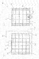
- Fig. 6 shows a schematically simplified top view of the IBC 76 with the assembly aid device 2 attached.
- connections 84 On the upper side 58 of the visible inner part are connections 84, of which only a few are provided with reference symbols for the sake of clarity, for connecting the vacuum source 72 or the vacuum line 74 to the suction channel 34 visible in the area of its conveying end 36.
Landscapes
- Engineering & Computer Science (AREA)
- Manufacturing & Machinery (AREA)
- Mechanical Engineering (AREA)
- Closures For Containers (AREA)
- Valves And Accessory Devices For Braking Systems (AREA)
- Quick-Acting Or Multi-Walled Pipe Joints (AREA)
Applications Claiming Priority (1)
| Application Number | Priority Date | Filing Date | Title |
|---|---|---|---|
| DE102020117230.3A DE102020117230B3 (de) | 2020-06-30 | 2020-06-30 | Montagehilfevorrichtung, System und Verfahren zur Anordnung einer Innenhülle in einem Flüssigkeitsbehälter, Verwendung der Montagehilfevorrichtung |
Publications (4)
| Publication Number | Publication Date |
|---|---|
| EP3932650A2 true EP3932650A2 (fr) | 2022-01-05 |
| EP3932650A3 EP3932650A3 (fr) | 2022-01-26 |
| EP3932650C0 EP3932650C0 (fr) | 2024-04-24 |
| EP3932650B1 EP3932650B1 (fr) | 2024-04-24 |
Family
ID=76971607
Family Applications (1)
| Application Number | Title | Priority Date | Filing Date |
|---|---|---|---|
| EP21180416.6A Active EP3932650B1 (fr) | 2020-06-30 | 2021-06-18 | Dispositif d'aide au montage, système et procédé de mise en place d'un manchon interne dans un récipient de liquide, utilisation du dispositif d'aide au montage |
Country Status (3)
| Country | Link |
|---|---|
| EP (1) | EP3932650B1 (fr) |
| DE (1) | DE102020117230B3 (fr) |
| ES (1) | ES2984539T3 (fr) |
Citations (1)
| Publication number | Priority date | Publication date | Assignee | Title |
|---|---|---|---|---|
| DE202014105594U1 (de) | 2014-11-20 | 2015-01-09 | Liquid Concept Gmbh & Co. Kg | Flüssigkeitsbehälter mit Innenhülle |
Family Cites Families (2)
| Publication number | Priority date | Publication date | Assignee | Title |
|---|---|---|---|---|
| DE202019102702U1 (de) | 2019-05-14 | 2019-05-22 | Ulrich Bahr | Inliner mit einer Entgasungslanze sowie mit einem Inliner versehener Transportbehälter |
| DE202020102645U1 (de) | 2020-05-12 | 2020-05-20 | Ulrich Bahr | Applikationshilfe und Applikationsanordnung für einen Inliner |
-
2020
- 2020-06-30 DE DE102020117230.3A patent/DE102020117230B3/de not_active Expired - Fee Related
-
2021
- 2021-06-18 EP EP21180416.6A patent/EP3932650B1/fr active Active
- 2021-06-18 ES ES21180416T patent/ES2984539T3/es active Active
Patent Citations (1)
| Publication number | Priority date | Publication date | Assignee | Title |
|---|---|---|---|---|
| DE202014105594U1 (de) | 2014-11-20 | 2015-01-09 | Liquid Concept Gmbh & Co. Kg | Flüssigkeitsbehälter mit Innenhülle |
Also Published As
| Publication number | Publication date |
|---|---|
| DE102020117230B3 (de) | 2021-09-16 |
| EP3932650A3 (fr) | 2022-01-26 |
| ES2984539T3 (es) | 2024-10-29 |
| EP3932650C0 (fr) | 2024-04-24 |
| EP3932650B1 (fr) | 2024-04-24 |
Similar Documents
| Publication | Publication Date | Title |
|---|---|---|
| DE69733800T2 (de) | Vorrichtung und Kartusche für einen umstülpbaren Schlauchbeutel | |
| DE69313414T2 (de) | Einsetzbarer barrieresack oder schicht für einen ausgabebehälter mit engem hals und verfahren zum füllen eines solchen papiersackes oder einer solchen schicht durch ein siphonrohr | |
| EP0663348B1 (fr) | Dispositif pour le vidage d'un sac tubulaire | |
| DE69705493T2 (de) | Verfahren und vorrichtung zum aufladen von druckmittelsystemen | |
| EP2403654B1 (fr) | Buse de réparation | |
| DE1926386A1 (de) | Abzapfeinrichtung | |
| CH671204A5 (fr) | ||
| DE2352029C2 (de) | Vorrichtung zum Abgeben von fließfähigem plastischen Material | |
| EP1982922A1 (fr) | Récipient et procédé destiné à l'ouverture d'un récipient | |
| DE3151892A1 (de) | Handpumpe zur druckfoerderung von fluessigkeiten und/oder dickfluessigen substanzen aus einem behaelter | |
| DE69115979T2 (de) | Behälter für Schüttgut mit biegsamer Verkleidung mit einem Mitnehmer | |
| EP1651356A1 (fr) | Emballage de distribution | |
| CH669165A5 (en) | Dispenser of paste-like product - has rigid cylindrical housing to receive product which is enclosed in flexible bag | |
| DE102020117230B3 (de) | Montagehilfevorrichtung, System und Verfahren zur Anordnung einer Innenhülle in einem Flüssigkeitsbehälter, Verwendung der Montagehilfevorrichtung | |
| EP3831500A1 (fr) | Dispositif d'arrimage, dispositif de soupape et dispositif de dosage ainsi que récipient associé | |
| DE2818719A1 (de) | Vorrichtung zum befestigen einer chromatographischen trennkolonne | |
| EP0286925B1 (fr) | Dispositif pour la distribution de liquides | |
| EP0352370B1 (fr) | Procédé et appareil pour ouvrir la membrane d' étanchéité dans la région débouchante d' une cartouche | |
| EP1588772A2 (fr) | Pompe de dosage et son procédé de fabrication | |
| DE4422606C1 (de) | Verfahren und Vorrichtung zum Schmelzen und Fördern von in einem Faß enthaltenem thermoplastischem Material, insbesondere Heißklebemittel | |
| EP1647507B1 (fr) | Dispositif de transport de matières solides dans un conduit | |
| EP0900164A1 (fr) | Procede et dispositif pour eviter l'emission de poussiere ou de gaz lors du transvasement avec des systemes doseurs de solides ou de liquides | |
| DE102023100940A1 (de) | Verschlussvorrichtung in Form einer Kappe zum fluiddichten Verschließen einer Düse und System mit einer Verschlussvorrichtung und einer Düse | |
| CH692143A5 (de) | Verfahren und Vorrichtung zur Vermeidung von Produktestaub- oder Produktegasaustritt bei Abfüllung mit Feststoff- oder Flüssigkeitsdosiersystemen. | |
| EP2062821A1 (fr) | Dispositif de remplissage d'un récipient avec un liquide |
Legal Events
| Date | Code | Title | Description |
|---|---|---|---|
| PUAI | Public reference made under article 153(3) epc to a published international application that has entered the european phase |
Free format text: ORIGINAL CODE: 0009012 |
|
| STAA | Information on the status of an ep patent application or granted ep patent |
Free format text: STATUS: THE APPLICATION HAS BEEN PUBLISHED |
|
| PUAL | Search report despatched |
Free format text: ORIGINAL CODE: 0009013 |
|
| AK | Designated contracting states |
Kind code of ref document: A2 Designated state(s): AL AT BE BG CH CY CZ DE DK EE ES FI FR GB GR HR HU IE IS IT LI LT LU LV MC MK MT NL NO PL PT RO RS SE SI SK SM TR |
|
| AK | Designated contracting states |
Kind code of ref document: A3 Designated state(s): AL AT BE BG CH CY CZ DE DK EE ES FI FR GB GR HR HU IE IS IT LI LT LU LV MC MK MT NL NO PL PT RO RS SE SI SK SM TR |
|
| RIC1 | Information provided on ipc code assigned before grant |
Ipc: B29C 63/00 20060101ALI20211223BHEP Ipc: B29C 63/26 20060101AFI20211223BHEP |
|
| STAA | Information on the status of an ep patent application or granted ep patent |
Free format text: STATUS: REQUEST FOR EXAMINATION WAS MADE |
|
| 17P | Request for examination filed |
Effective date: 20220707 |
|
| RBV | Designated contracting states (corrected) |
Designated state(s): AL AT BE BG CH CY CZ DE DK EE ES FI FR GB GR HR HU IE IS IT LI LT LU LV MC MK MT NL NO PL PT RO RS SE SI SK SM TR |
|
| GRAP | Despatch of communication of intention to grant a patent |
Free format text: ORIGINAL CODE: EPIDOSNIGR1 |
|
| STAA | Information on the status of an ep patent application or granted ep patent |
Free format text: STATUS: GRANT OF PATENT IS INTENDED |
|
| RIC1 | Information provided on ipc code assigned before grant |
Ipc: B29C 63/00 20060101ALI20231026BHEP Ipc: B29C 63/26 20060101AFI20231026BHEP |
|
| INTG | Intention to grant announced |
Effective date: 20231116 |
|
| GRAS | Grant fee paid |
Free format text: ORIGINAL CODE: EPIDOSNIGR3 |
|
| GRAA | (expected) grant |
Free format text: ORIGINAL CODE: 0009210 |
|
| STAA | Information on the status of an ep patent application or granted ep patent |
Free format text: STATUS: THE PATENT HAS BEEN GRANTED |
|
| AK | Designated contracting states |
Kind code of ref document: B1 Designated state(s): AL AT BE BG CH CY CZ DE DK EE ES FI FR GB GR HR HU IE IS IT LI LT LU LV MC MK MT NL NO PL PT RO RS SE SI SK SM TR |
|
| RAP3 | Party data changed (applicant data changed or rights of an application transferred) |
Owner name: LIQUID CONCEPT GMBH & CO. KG |
|
| REG | Reference to a national code |
Ref country code: GB Ref legal event code: FG4D Free format text: NOT ENGLISH |
|
| REG | Reference to a national code |
Ref country code: CH Ref legal event code: EP |
|
| REG | Reference to a national code |
Ref country code: DE Ref legal event code: R096 Ref document number: 502021003439 Country of ref document: DE |
|
| REG | Reference to a national code |
Ref country code: IE Ref legal event code: FG4D Free format text: LANGUAGE OF EP DOCUMENT: GERMAN |
|
| U01 | Request for unitary effect filed |
Effective date: 20240522 |
|
| U07 | Unitary effect registered |
Designated state(s): AT BE BG DE DK EE FI FR IT LT LU LV MT NL PT SE SI Effective date: 20240603 |
|
| U20 | Renewal fee for the european patent with unitary effect paid |
Year of fee payment: 4 Effective date: 20240822 |
|
| PG25 | Lapsed in a contracting state [announced via postgrant information from national office to epo] |
Ref country code: IS Free format text: LAPSE BECAUSE OF FAILURE TO SUBMIT A TRANSLATION OF THE DESCRIPTION OR TO PAY THE FEE WITHIN THE PRESCRIBED TIME-LIMIT Effective date: 20240824 |
|
| PG25 | Lapsed in a contracting state [announced via postgrant information from national office to epo] |
Ref country code: HR Free format text: LAPSE BECAUSE OF FAILURE TO SUBMIT A TRANSLATION OF THE DESCRIPTION OR TO PAY THE FEE WITHIN THE PRESCRIBED TIME-LIMIT Effective date: 20240424 |
|
| PG25 | Lapsed in a contracting state [announced via postgrant information from national office to epo] |
Ref country code: GR Free format text: LAPSE BECAUSE OF FAILURE TO SUBMIT A TRANSLATION OF THE DESCRIPTION OR TO PAY THE FEE WITHIN THE PRESCRIBED TIME-LIMIT Effective date: 20240725 |
|
| PG25 | Lapsed in a contracting state [announced via postgrant information from national office to epo] |
Ref country code: PL Free format text: LAPSE BECAUSE OF FAILURE TO SUBMIT A TRANSLATION OF THE DESCRIPTION OR TO PAY THE FEE WITHIN THE PRESCRIBED TIME-LIMIT Effective date: 20240424 |
|
| REG | Reference to a national code |
Ref country code: ES Ref legal event code: FG2A Ref document number: 2984539 Country of ref document: ES Kind code of ref document: T3 Effective date: 20241029 |
|
| PG25 | Lapsed in a contracting state [announced via postgrant information from national office to epo] |
Ref country code: PL Free format text: LAPSE BECAUSE OF FAILURE TO SUBMIT A TRANSLATION OF THE DESCRIPTION OR TO PAY THE FEE WITHIN THE PRESCRIBED TIME-LIMIT Effective date: 20240424 Ref country code: NO Free format text: LAPSE BECAUSE OF FAILURE TO SUBMIT A TRANSLATION OF THE DESCRIPTION OR TO PAY THE FEE WITHIN THE PRESCRIBED TIME-LIMIT Effective date: 20240724 Ref country code: IS Free format text: LAPSE BECAUSE OF FAILURE TO SUBMIT A TRANSLATION OF THE DESCRIPTION OR TO PAY THE FEE WITHIN THE PRESCRIBED TIME-LIMIT Effective date: 20240824 Ref country code: HR Free format text: LAPSE BECAUSE OF FAILURE TO SUBMIT A TRANSLATION OF THE DESCRIPTION OR TO PAY THE FEE WITHIN THE PRESCRIBED TIME-LIMIT Effective date: 20240424 Ref country code: GR Free format text: LAPSE BECAUSE OF FAILURE TO SUBMIT A TRANSLATION OF THE DESCRIPTION OR TO PAY THE FEE WITHIN THE PRESCRIBED TIME-LIMIT Effective date: 20240725 Ref country code: RS Free format text: LAPSE BECAUSE OF FAILURE TO SUBMIT A TRANSLATION OF THE DESCRIPTION OR TO PAY THE FEE WITHIN THE PRESCRIBED TIME-LIMIT Effective date: 20240724 |
|
| PG25 | Lapsed in a contracting state [announced via postgrant information from national office to epo] |
Ref country code: CZ Free format text: LAPSE BECAUSE OF FAILURE TO SUBMIT A TRANSLATION OF THE DESCRIPTION OR TO PAY THE FEE WITHIN THE PRESCRIBED TIME-LIMIT Effective date: 20240424 |
|
| PG25 | Lapsed in a contracting state [announced via postgrant information from national office to epo] |
Ref country code: RO Free format text: LAPSE BECAUSE OF FAILURE TO SUBMIT A TRANSLATION OF THE DESCRIPTION OR TO PAY THE FEE WITHIN THE PRESCRIBED TIME-LIMIT Effective date: 20240424 Ref country code: SK Free format text: LAPSE BECAUSE OF FAILURE TO SUBMIT A TRANSLATION OF THE DESCRIPTION OR TO PAY THE FEE WITHIN THE PRESCRIBED TIME-LIMIT Effective date: 20240424 |
|
| REG | Reference to a national code |
Ref country code: DE Ref legal event code: R097 Ref document number: 502021003439 Country of ref document: DE |
|
| PG25 | Lapsed in a contracting state [announced via postgrant information from national office to epo] |
Ref country code: SM Free format text: LAPSE BECAUSE OF FAILURE TO SUBMIT A TRANSLATION OF THE DESCRIPTION OR TO PAY THE FEE WITHIN THE PRESCRIBED TIME-LIMIT Effective date: 20240424 |
|
| PG25 | Lapsed in a contracting state [announced via postgrant information from national office to epo] |
Ref country code: SM Free format text: LAPSE BECAUSE OF FAILURE TO SUBMIT A TRANSLATION OF THE DESCRIPTION OR TO PAY THE FEE WITHIN THE PRESCRIBED TIME-LIMIT Effective date: 20240424 Ref country code: SK Free format text: LAPSE BECAUSE OF FAILURE TO SUBMIT A TRANSLATION OF THE DESCRIPTION OR TO PAY THE FEE WITHIN THE PRESCRIBED TIME-LIMIT Effective date: 20240424 Ref country code: RO Free format text: LAPSE BECAUSE OF FAILURE TO SUBMIT A TRANSLATION OF THE DESCRIPTION OR TO PAY THE FEE WITHIN THE PRESCRIBED TIME-LIMIT Effective date: 20240424 Ref country code: CZ Free format text: LAPSE BECAUSE OF FAILURE TO SUBMIT A TRANSLATION OF THE DESCRIPTION OR TO PAY THE FEE WITHIN THE PRESCRIBED TIME-LIMIT Effective date: 20240424 Ref country code: MC Free format text: LAPSE BECAUSE OF FAILURE TO SUBMIT A TRANSLATION OF THE DESCRIPTION OR TO PAY THE FEE WITHIN THE PRESCRIBED TIME-LIMIT Effective date: 20240424 |
|
| REG | Reference to a national code |
Ref country code: CH Ref legal event code: PL |
|
| PLBE | No opposition filed within time limit |
Free format text: ORIGINAL CODE: 0009261 |
|
| STAA | Information on the status of an ep patent application or granted ep patent |
Free format text: STATUS: NO OPPOSITION FILED WITHIN TIME LIMIT |
|
| 26N | No opposition filed |
Effective date: 20250127 |
|
| PG25 | Lapsed in a contracting state [announced via postgrant information from national office to epo] |
Ref country code: IE Free format text: LAPSE BECAUSE OF NON-PAYMENT OF DUE FEES Effective date: 20240618 |
|
| PG25 | Lapsed in a contracting state [announced via postgrant information from national office to epo] |
Ref country code: CH Free format text: LAPSE BECAUSE OF NON-PAYMENT OF DUE FEES Effective date: 20240630 |
|
| U20 | Renewal fee for the european patent with unitary effect paid |
Year of fee payment: 5 Effective date: 20250623 |
|
| PGFP | Annual fee paid to national office [announced via postgrant information from national office to epo] |
Ref country code: ES Payment date: 20250718 Year of fee payment: 5 |
|
| PG25 | Lapsed in a contracting state [announced via postgrant information from national office to epo] |
Ref country code: CY Free format text: LAPSE BECAUSE OF FAILURE TO SUBMIT A TRANSLATION OF THE DESCRIPTION OR TO PAY THE FEE WITHIN THE PRESCRIBED TIME-LIMIT; INVALID AB INITIO Effective date: 20210618 |
|
| GBPC | Gb: european patent ceased through non-payment of renewal fee |
Effective date: 20250618 |
|
| PG25 | Lapsed in a contracting state [announced via postgrant information from national office to epo] |
Ref country code: HU Free format text: LAPSE BECAUSE OF FAILURE TO SUBMIT A TRANSLATION OF THE DESCRIPTION OR TO PAY THE FEE WITHIN THE PRESCRIBED TIME-LIMIT; INVALID AB INITIO Effective date: 20210618 |
|
| PG25 | Lapsed in a contracting state [announced via postgrant information from national office to epo] |
Ref country code: GB Free format text: LAPSE BECAUSE OF NON-PAYMENT OF DUE FEES Effective date: 20250618 |