EP3932664B1 - Lichtleiterplatte und transparentes beleuchtungssystem damit - Google Patents
Lichtleiterplatte und transparentes beleuchtungssystem damit Download PDFInfo
- Publication number
- EP3932664B1 EP3932664B1 EP21182549.2A EP21182549A EP3932664B1 EP 3932664 B1 EP3932664 B1 EP 3932664B1 EP 21182549 A EP21182549 A EP 21182549A EP 3932664 B1 EP3932664 B1 EP 3932664B1
- Authority
- EP
- European Patent Office
- Prior art keywords
- light
- light guide
- glass
- layer
- refraction
- Prior art date
- Legal status (The legal status is an assumption and is not a legal conclusion. Google has not performed a legal analysis and makes no representation as to the accuracy of the status listed.)
- Active
Links
Images



Classifications
-
- G—PHYSICS
- G02—OPTICS
- G02B—OPTICAL ELEMENTS, SYSTEMS OR APPARATUS
- G02B6/00—Light guides; Structural details of arrangements comprising light guides and other optical elements, e.g. couplings
- G02B6/0001—Light guides; Structural details of arrangements comprising light guides and other optical elements, e.g. couplings specially adapted for lighting devices or systems
- G02B6/0011—Light guides; Structural details of arrangements comprising light guides and other optical elements, e.g. couplings specially adapted for lighting devices or systems the light guides being planar or of plate-like form
- G02B6/0033—Means for improving the coupling-out of light from the light guide
- G02B6/0035—Means for improving the coupling-out of light from the light guide provided on the surface of the light guide or in the bulk of it
- G02B6/004—Scattering dots or dot-like elements, e.g. microbeads, scattering particles, nanoparticles
- G02B6/0041—Scattering dots or dot-like elements, e.g. microbeads, scattering particles, nanoparticles provided in the bulk of the light guide
-
- B—PERFORMING OPERATIONS; TRANSPORTING
- B32—LAYERED PRODUCTS
- B32B—LAYERED PRODUCTS, i.e. PRODUCTS BUILT-UP OF STRATA OF FLAT OR NON-FLAT, e.g. CELLULAR OR HONEYCOMB, FORM
- B32B17/00—Layered products essentially comprising sheet glass, or glass, slag, or like fibres
- B32B17/06—Layered products essentially comprising sheet glass, or glass, slag, or like fibres comprising glass as the main or only constituent of a layer, next to another layer of a specific material
- B32B17/10—Layered products essentially comprising sheet glass, or glass, slag, or like fibres comprising glass as the main or only constituent of a layer, next to another layer of a specific material of synthetic resin
- B32B17/10005—Layered products essentially comprising sheet glass, or glass, slag, or like fibres comprising glass as the main or only constituent of a layer, next to another layer of a specific material of synthetic resin laminated safety glass or glazing
- B32B17/10009—Layered products essentially comprising sheet glass, or glass, slag, or like fibres comprising glass as the main or only constituent of a layer, next to another layer of a specific material of synthetic resin laminated safety glass or glazing characterized by the number, the constitution or treatment of glass sheets
- B32B17/10036—Layered products essentially comprising sheet glass, or glass, slag, or like fibres comprising glass as the main or only constituent of a layer, next to another layer of a specific material of synthetic resin laminated safety glass or glazing characterized by the number, the constitution or treatment of glass sheets comprising two outer glass sheets
- B32B17/10045—Layered products essentially comprising sheet glass, or glass, slag, or like fibres comprising glass as the main or only constituent of a layer, next to another layer of a specific material of synthetic resin laminated safety glass or glazing characterized by the number, the constitution or treatment of glass sheets comprising two outer glass sheets with at least one intermediate layer consisting of a glass sheet
-
- B—PERFORMING OPERATIONS; TRANSPORTING
- B32—LAYERED PRODUCTS
- B32B—LAYERED PRODUCTS, i.e. PRODUCTS BUILT-UP OF STRATA OF FLAT OR NON-FLAT, e.g. CELLULAR OR HONEYCOMB, FORM
- B32B17/00—Layered products essentially comprising sheet glass, or glass, slag, or like fibres
- B32B17/06—Layered products essentially comprising sheet glass, or glass, slag, or like fibres comprising glass as the main or only constituent of a layer, next to another layer of a specific material
- B32B17/10—Layered products essentially comprising sheet glass, or glass, slag, or like fibres comprising glass as the main or only constituent of a layer, next to another layer of a specific material of synthetic resin
- B32B17/10005—Layered products essentially comprising sheet glass, or glass, slag, or like fibres comprising glass as the main or only constituent of a layer, next to another layer of a specific material of synthetic resin laminated safety glass or glazing
- B32B17/10009—Layered products essentially comprising sheet glass, or glass, slag, or like fibres comprising glass as the main or only constituent of a layer, next to another layer of a specific material of synthetic resin laminated safety glass or glazing characterized by the number, the constitution or treatment of glass sheets
- B32B17/10018—Layered products essentially comprising sheet glass, or glass, slag, or like fibres comprising glass as the main or only constituent of a layer, next to another layer of a specific material of synthetic resin laminated safety glass or glazing characterized by the number, the constitution or treatment of glass sheets comprising only one glass sheet
-
- B—PERFORMING OPERATIONS; TRANSPORTING
- B32—LAYERED PRODUCTS
- B32B—LAYERED PRODUCTS, i.e. PRODUCTS BUILT-UP OF STRATA OF FLAT OR NON-FLAT, e.g. CELLULAR OR HONEYCOMB, FORM
- B32B17/00—Layered products essentially comprising sheet glass, or glass, slag, or like fibres
- B32B17/06—Layered products essentially comprising sheet glass, or glass, slag, or like fibres comprising glass as the main or only constituent of a layer, next to another layer of a specific material
- B32B17/10—Layered products essentially comprising sheet glass, or glass, slag, or like fibres comprising glass as the main or only constituent of a layer, next to another layer of a specific material of synthetic resin
- B32B17/10005—Layered products essentially comprising sheet glass, or glass, slag, or like fibres comprising glass as the main or only constituent of a layer, next to another layer of a specific material of synthetic resin laminated safety glass or glazing
- B32B17/10009—Layered products essentially comprising sheet glass, or glass, slag, or like fibres comprising glass as the main or only constituent of a layer, next to another layer of a specific material of synthetic resin laminated safety glass or glazing characterized by the number, the constitution or treatment of glass sheets
- B32B17/10082—Properties of the bulk of a glass sheet
- B32B17/10091—Properties of the bulk of a glass sheet thermally hardened
-
- B—PERFORMING OPERATIONS; TRANSPORTING
- B32—LAYERED PRODUCTS
- B32B—LAYERED PRODUCTS, i.e. PRODUCTS BUILT-UP OF STRATA OF FLAT OR NON-FLAT, e.g. CELLULAR OR HONEYCOMB, FORM
- B32B17/00—Layered products essentially comprising sheet glass, or glass, slag, or like fibres
- B32B17/06—Layered products essentially comprising sheet glass, or glass, slag, or like fibres comprising glass as the main or only constituent of a layer, next to another layer of a specific material
- B32B17/10—Layered products essentially comprising sheet glass, or glass, slag, or like fibres comprising glass as the main or only constituent of a layer, next to another layer of a specific material of synthetic resin
- B32B17/10005—Layered products essentially comprising sheet glass, or glass, slag, or like fibres comprising glass as the main or only constituent of a layer, next to another layer of a specific material of synthetic resin laminated safety glass or glazing
- B32B17/10009—Layered products essentially comprising sheet glass, or glass, slag, or like fibres comprising glass as the main or only constituent of a layer, next to another layer of a specific material of synthetic resin laminated safety glass or glazing characterized by the number, the constitution or treatment of glass sheets
- B32B17/10128—Treatment of at least one glass sheet
- B32B17/10137—Chemical strengthening
-
- B—PERFORMING OPERATIONS; TRANSPORTING
- B32—LAYERED PRODUCTS
- B32B—LAYERED PRODUCTS, i.e. PRODUCTS BUILT-UP OF STRATA OF FLAT OR NON-FLAT, e.g. CELLULAR OR HONEYCOMB, FORM
- B32B17/00—Layered products essentially comprising sheet glass, or glass, slag, or like fibres
- B32B17/06—Layered products essentially comprising sheet glass, or glass, slag, or like fibres comprising glass as the main or only constituent of a layer, next to another layer of a specific material
- B32B17/10—Layered products essentially comprising sheet glass, or glass, slag, or like fibres comprising glass as the main or only constituent of a layer, next to another layer of a specific material of synthetic resin
- B32B17/10005—Layered products essentially comprising sheet glass, or glass, slag, or like fibres comprising glass as the main or only constituent of a layer, next to another layer of a specific material of synthetic resin laminated safety glass or glazing
- B32B17/10165—Functional features of the laminated safety glass or glazing
- B32B17/10541—Functional features of the laminated safety glass or glazing comprising a light source or a light guide
-
- B—PERFORMING OPERATIONS; TRANSPORTING
- B32—LAYERED PRODUCTS
- B32B—LAYERED PRODUCTS, i.e. PRODUCTS BUILT-UP OF STRATA OF FLAT OR NON-FLAT, e.g. CELLULAR OR HONEYCOMB, FORM
- B32B7/00—Layered products characterised by the relation between layers; Layered products characterised by the relative orientation of features between layers, or by the relative values of a measurable parameter between layers, i.e. products comprising layers having different physical, chemical or physicochemical properties; Layered products characterised by the interconnection of layers
- B32B7/02—Physical, chemical or physicochemical properties
- B32B7/023—Optical properties
-
- B—PERFORMING OPERATIONS; TRANSPORTING
- B60—VEHICLES IN GENERAL
- B60Q—ARRANGEMENT OF SIGNALLING OR LIGHTING DEVICES, THE MOUNTING OR SUPPORTING THEREOF OR CIRCUITS THEREFOR, FOR VEHICLES IN GENERAL
- B60Q3/00—Arrangement of lighting devices for vehicle interiors; Lighting devices specially adapted for vehicle interiors
- B60Q3/20—Arrangement of lighting devices for vehicle interiors; Lighting devices specially adapted for vehicle interiors for lighting specific fittings of passenger or driving compartments; mounted on specific fittings of passenger or driving compartments
- B60Q3/208—Sun roofs; Windows
-
- B—PERFORMING OPERATIONS; TRANSPORTING
- B60—VEHICLES IN GENERAL
- B60Q—ARRANGEMENT OF SIGNALLING OR LIGHTING DEVICES, THE MOUNTING OR SUPPORTING THEREOF OR CIRCUITS THEREFOR, FOR VEHICLES IN GENERAL
- B60Q3/00—Arrangement of lighting devices for vehicle interiors; Lighting devices specially adapted for vehicle interiors
- B60Q3/60—Arrangement of lighting devices for vehicle interiors; Lighting devices specially adapted for vehicle interiors characterised by optical aspects
- B60Q3/62—Arrangement of lighting devices for vehicle interiors; Lighting devices specially adapted for vehicle interiors characterised by optical aspects using light guides
-
- B—PERFORMING OPERATIONS; TRANSPORTING
- B60—VEHICLES IN GENERAL
- B60Q—ARRANGEMENT OF SIGNALLING OR LIGHTING DEVICES, THE MOUNTING OR SUPPORTING THEREOF OR CIRCUITS THEREFOR, FOR VEHICLES IN GENERAL
- B60Q3/00—Arrangement of lighting devices for vehicle interiors; Lighting devices specially adapted for vehicle interiors
- B60Q3/70—Arrangement of lighting devices for vehicle interiors; Lighting devices specially adapted for vehicle interiors characterised by the purpose
- B60Q3/74—Arrangement of lighting devices for vehicle interiors; Lighting devices specially adapted for vehicle interiors characterised by the purpose for overall compartment lighting; for overall compartment lighting in combination with specific lighting, e.g. room lamps with reading lamps
-
- G—PHYSICS
- G02—OPTICS
- G02B—OPTICAL ELEMENTS, SYSTEMS OR APPARATUS
- G02B6/00—Light guides; Structural details of arrangements comprising light guides and other optical elements, e.g. couplings
- G02B6/0001—Light guides; Structural details of arrangements comprising light guides and other optical elements, e.g. couplings specially adapted for lighting devices or systems
- G02B6/0011—Light guides; Structural details of arrangements comprising light guides and other optical elements, e.g. couplings specially adapted for lighting devices or systems the light guides being planar or of plate-like form
- G02B6/0013—Means for improving the coupling-in of light from the light source into the light guide
- G02B6/0015—Means for improving the coupling-in of light from the light source into the light guide provided on the surface of the light guide or in the bulk of it
- G02B6/002—Means for improving the coupling-in of light from the light source into the light guide provided on the surface of the light guide or in the bulk of it by shaping at least a portion of the light guide, e.g. with collimating, focussing or diverging surfaces
-
- G—PHYSICS
- G02—OPTICS
- G02B—OPTICAL ELEMENTS, SYSTEMS OR APPARATUS
- G02B6/00—Light guides; Structural details of arrangements comprising light guides and other optical elements, e.g. couplings
- G02B6/0001—Light guides; Structural details of arrangements comprising light guides and other optical elements, e.g. couplings specially adapted for lighting devices or systems
- G02B6/0011—Light guides; Structural details of arrangements comprising light guides and other optical elements, e.g. couplings specially adapted for lighting devices or systems the light guides being planar or of plate-like form
- G02B6/0013—Means for improving the coupling-in of light from the light source into the light guide
- G02B6/0023—Means for improving the coupling-in of light from the light source into the light guide provided by one optical element, or plurality thereof, placed between the light guide and the light source, or around the light source
-
- G—PHYSICS
- G02—OPTICS
- G02B—OPTICAL ELEMENTS, SYSTEMS OR APPARATUS
- G02B6/00—Light guides; Structural details of arrangements comprising light guides and other optical elements, e.g. couplings
- G02B6/0001—Light guides; Structural details of arrangements comprising light guides and other optical elements, e.g. couplings specially adapted for lighting devices or systems
- G02B6/0011—Light guides; Structural details of arrangements comprising light guides and other optical elements, e.g. couplings specially adapted for lighting devices or systems the light guides being planar or of plate-like form
- G02B6/0013—Means for improving the coupling-in of light from the light source into the light guide
- G02B6/0023—Means for improving the coupling-in of light from the light source into the light guide provided by one optical element, or plurality thereof, placed between the light guide and the light source, or around the light source
- G02B6/003—Lens or lenticular sheet or layer
-
- G—PHYSICS
- G02—OPTICS
- G02B—OPTICAL ELEMENTS, SYSTEMS OR APPARATUS
- G02B6/00—Light guides; Structural details of arrangements comprising light guides and other optical elements, e.g. couplings
- G02B6/0001—Light guides; Structural details of arrangements comprising light guides and other optical elements, e.g. couplings specially adapted for lighting devices or systems
- G02B6/0011—Light guides; Structural details of arrangements comprising light guides and other optical elements, e.g. couplings specially adapted for lighting devices or systems the light guides being planar or of plate-like form
- G02B6/0033—Means for improving the coupling-out of light from the light guide
- G02B6/005—Means for improving the coupling-out of light from the light guide provided by one optical element, or plurality thereof, placed on the light output side of the light guide
- G02B6/0051—Diffusing sheet or layer
-
- G—PHYSICS
- G02—OPTICS
- G02B—OPTICAL ELEMENTS, SYSTEMS OR APPARATUS
- G02B6/00—Light guides; Structural details of arrangements comprising light guides and other optical elements, e.g. couplings
- G02B6/0001—Light guides; Structural details of arrangements comprising light guides and other optical elements, e.g. couplings specially adapted for lighting devices or systems
- G02B6/0011—Light guides; Structural details of arrangements comprising light guides and other optical elements, e.g. couplings specially adapted for lighting devices or systems the light guides being planar or of plate-like form
- G02B6/0065—Manufacturing aspects; Material aspects
-
- G—PHYSICS
- G02—OPTICS
- G02B—OPTICAL ELEMENTS, SYSTEMS OR APPARATUS
- G02B6/00—Light guides; Structural details of arrangements comprising light guides and other optical elements, e.g. couplings
- G02B6/0001—Light guides; Structural details of arrangements comprising light guides and other optical elements, e.g. couplings specially adapted for lighting devices or systems
- G02B6/0011—Light guides; Structural details of arrangements comprising light guides and other optical elements, e.g. couplings specially adapted for lighting devices or systems the light guides being planar or of plate-like form
- G02B6/0033—Means for improving the coupling-out of light from the light guide
- G02B6/0035—Means for improving the coupling-out of light from the light guide provided on the surface of the light guide or in the bulk of it
- G02B6/0036—2-D arrangement of prisms, protrusions, indentations or roughened surfaces
-
- G—PHYSICS
- G02—OPTICS
- G02B—OPTICAL ELEMENTS, SYSTEMS OR APPARATUS
- G02B6/00—Light guides; Structural details of arrangements comprising light guides and other optical elements, e.g. couplings
- G02B6/0001—Light guides; Structural details of arrangements comprising light guides and other optical elements, e.g. couplings specially adapted for lighting devices or systems
- G02B6/0011—Light guides; Structural details of arrangements comprising light guides and other optical elements, e.g. couplings specially adapted for lighting devices or systems the light guides being planar or of plate-like form
- G02B6/0033—Means for improving the coupling-out of light from the light guide
- G02B6/0035—Means for improving the coupling-out of light from the light guide provided on the surface of the light guide or in the bulk of it
- G02B6/004—Scattering dots or dot-like elements, e.g. microbeads, scattering particles, nanoparticles
Definitions
- the disclosure relates generally to light guide plates and more particularly to a light guide plate used for a transparent illumination system.
- transparent glass articles such as windows, doors, sunroofs, skylights, etc.
- transparent devices do not include devices that also deliver illumination light out of a major surface of the glass article.
- US 2017/139109 A1 , US 2018/215312 A1 , US 2014/204601 A1 , US 2018/086028 A1 and US 2011/267833 A1 relate to glazing assemblies made luminous by illuminating a glass sheet via an edge face with a light source.
- the claimed invention provides a transparent illumination system, as claimed in claim 1.
- the transparent illumination system includes a light diffusing, light guide layer, a strengthened structural glass layer coupled to the light guide layer and a light source optically coupled to the minor edge surface of the light guide layer.
- the light diffusing, light guide layer includes a first glass material, a first major surface, a second major surface opposite the first major surface, a minor edge surface connecting the first major surface to the second major surface and a plurality of light extraction features.
- the transparent illumination system includes an optical element located between the light source and the minor edge surface of the light guide layer, and the optical element is configured to increase an angular emission of light from the light source in a plane perpendicular to the minor edge surface. Light from the light source is transmitted across the light guide layer via total internal reflection, and the light extraction features are configured to direct light out of the light guide layer and through the first major surface.
- An additional aspect of the disclosure relates to a light-diffusing, light guide plate that includes a first glass material, a first major surface, a second major surface opposite the first major surface and a minor edge surface connecting the first major surface to the second major surface.
- the light-diffusing, light guide plate includes a central region located between the first and second major surfaces, a first exterior region extending from the central region to the first major surface, and a second exterior region extending from the central region to the second major surface.
- the light-diffusing, light guide plate includes a thickness measured between the first major surface and the second major surface of 0.3 mm to 5 mm, a width greater than 20 cm and a length greater than 20 cm.
- the light-diffusing, light guide plate includes a high transmittance, Tx, greater than 70% at wavelengths of light between 550 nm through 500 mm and a plurality of light extraction features located in the central region, wherein the first and second exterior regions are substantially devoid of light extraction features.
- An additional aspect of the disclosure relates to a light-diffusing, light guide plate including a central glass layer.
- the central glass layer includes a first glass material, a first major surface, a second major surface opposite the first major surface, a minor edge surface connecting the first major surface to the second major surface and a plurality of light extraction features configured to direct light out of the central glass layer and through the first major surface.
- the light-diffusing, light guide plate includes a first cladding layer formed from a second glass material different from the first glass material, and the first cladding layer is directly coupled to the first major surface.
- the first glass material has a first index of refraction and the second glass material has a second index of refraction.
- the first index of refraction is greater than the second index of refraction, and a difference between the first index of refraction and the second index of refraction is greater than 0.01 and 0.2.
- a light guide plate is directly attached to other high index materials in a glass laminate article (e.g., the optical adhesive layer materials, such PVB, common in automotive laminate applications) which provides a challenge for waveguide transmission through the light guide plate due to the low index of refraction (IR) difference between the light guide layer and the typical adjacent layer.
- IR index of refraction
- the designs discussed herein utilize a light source with a low angular emission (spread of light from the source) range (at least in the direction of the major surfaces of the light guide plate) to allow light coupled into the light guide plate to propagate via total internal reflection (TIR) despite the low IR difference with adjacent layers.
- TIR total internal reflection
- Applicant has further determined that such light sources tend to also have low angular emission in the plane within in the glass plate (e.g., a plane generally parallel to the major surfaces of the glass and/or perpendicular to a minor edge surface of the glass plate) which in turn results in unsatisfactory or uneven light distribution within the plate.
- the light guide plate includes light extraction features (LEFs) embedded within the glass material of the light guide plate. Applicant has determined that by locating the LEFs away from the exterior surfaces of such devices the illumination performance can be improved.
- LEFs light extraction features
- Applicant has determined that many illumination applications for a light diffusing (spreading, widening), light guide (control, influencing) plate are utilized in environments where the index of refraction at the external surface of a glass article is hard to control, e.g., due to contaminants, fingerprints, water, etc., that may be in contact with one of the surfaces of a glass article of such a device.
- This localized change in IR difference may result in unintended light leakage at such locations decreasing the performance of the illumination device.
- Applicant has addressed this problem by designing a light guide plate in which most or all of the LEFs are located spaced from the exterior surface that such surface contaminant issues have little or no impact on the illumination properties of the systems discussed herein.
- transparent illumination system 10 includes a glass laminate article 12, a light source 14 and an optical element 16.
- glass laminate article 12 is a multilayer component having one or more glass layers, that may serve as a window, glass door, sunroof, skylight, etc. in a wide variety of applications, such as structural, vehicular and/or architectural applications.
- Light source 14 generates light that is coupled into a light guide layer of glass laminate article 12.
- Optical element 16 is an optical device configured to enhance light distribution within the light guide layer and/or to facilitate coupling of light into the light guide layer. Details of light source 14 and optical element 16 are discussed in detail below.
- Glass laminate article 12 includes a structural glass layer 18, a first intermediate layer, shown as polymer interlayer 20, a light guide plate, shown as multilayer light guide plate 22.
- structural glass layer 18 is a relatively thick layer of glass material, such as strengthened (having compression on exterior surfaces offset by tension elsewhere; e.g., ion-exchanged, chemically tempered, thermally tempered), tempered or non-tempered glass, such as a thermally tempered soda lime glass.
- Structural glass layer 18 provides the primary structural function to glass laminate article 12.
- structural glass layer 18 is low-iron soda lime glass, or tinted soda lime glass.
- polymer interlayer 20 is an optical adhesive layer that couples structural glass layer 18 to multilayer light guide plate 22.
- polymer interlayer 20 is polyvinyl butyral (PVB).
- PVB polyvinyl butyral
- polymer interlayer 20 is a modified PVB, such as acoustic PVB, which is designed to reduce sound transmission through glass laminate article 12 by a certain amount, e.g., PVB designed to reduce sound transmission through the glass laminate article 12 by up to 5 dBs.
- polymer interlayer 20 is a solar radiation limiting PVB, which is designed to reduce infrared transmission through glass laminate article 12 from solar radiation, e.g., PVB designed to transmit less than 30% of infrared radiation from the sun through the glass laminate article 12.
- polymer interlayer 20 is ethylene vinyl acetate or SentryGlas ® .
- light guide plate 22 includes a light diffusing, light guide layer, shown as waveguide sheet 24, a second intermediate layer, show as a first cladding layer 26, and an external layer, show a second cladding layer 28.
- Second cladding layer 28 is coupled to a first major surface 30 of waveguide sheet 24, and first cladding layer 26 is coupled to a second major surface 32 of waveguide sheet 24.
- second cladding layer 28 is directly coupled to a first major surface 30 of waveguide sheet 24, and first cladding layer 26 is directly coupled to a second major surface 32 of waveguide sheet 24.
- polymer interlayer 20 is located between first cladding layer 26 and structural glass 18.
- additional layers within laminated glass article 12 tend to have very poor transmission properties that may rapidly absorb light if such layers were optically coupled to the light guide layer, such as waveguide sheet 24.
- cladding layer 26 optically isolates the light guide sheet 24 from polymer interlayer 20 and cladding layer 28 protects the other major surface of sheet 24 from surface contaminates that may impact illumination performance.
- light guide plate 22 is formed entirely from glass materials.
- Applicant has determined that the all-glass configuration enables high-temperature operation such as in automotive applications.
- the all-glass configuration of light guide plate 22 enables resistance to environmental conditions such as heat, humidity, UV radiation, salt, cleaning solvents, body oils, water and other chemicals.
- This all glass design of the light guide plate is contrasted with other arrangements that may use optical plastic layers and/or surface printed light extraction features that do not handle temperature or harsh environmental conditions as well as the all glass light guide plate discussed herein.
- glass laminate article 12 can be sized and/or structured for a wide range of applications, in specific embodiments, glass laminate article 12 is sized for an automotive glass application and specifically an automotive sunroof application.
- waveguide sheet 24 has a thickness measured between first major surface 30 and second major surface 32 of 0.3 mm to 5 mm. Thicknesses of the first and second cladding layers 26 and 28 are between 1 micrometer and 1000 micrometers.
- structural glass layer 18 has a thickness of 0.5 to 4 mm.
- glass article 12 has width and length dimensions for use in a structural, vehicular or architectural application. In specific embodiments, glass article 18 has a width greater than 20 cm and/or a length greater than 20 cm.
- glass laminate article 12 may be rectangular, square, circular or any other shape as desired for a particular application. In various embodiments, glass laminate article 12 may be flat. In various other embodiments, glass laminate article 12 may be curved. In such embodiments, glass laminate article 12 may curved along one or two axes. In various embodiments, the minimum radius of curvature along one or two axes of curvature is 500 mm, preferably 1000 mm, and more preferably 2000 mm.
- Waveguide sheet 24 includes a plurality of light extraction features (LEFs) 34 located in a central region of sheet 24.
- Waveguide sheet 24 includes a first exterior region located between the central region with LEFs 34 and first major surface 30, and a second exterior region located between central region with LEFs 34 and second major surface 32.
- the first and second exterior regions of waveguide sheet 24 are substantially devoid of LEFs.
- the number of LEFs in the exterior regions of waveguide sheet 24 are less 1% of the number of LEFs in the central region of waveguide sheet 24, and in an even more specific embodiment, there are no LEFs in the exterior regions of waveguide sheet 24.
- cladding layers 26 and 28 are substantially devoid of LEFs.
- the number of LEFs in cladding layers 26 and 28 are less 1% of the number of LEFs in the central region of waveguide sheet 24, and in an even more specific embodiment, there are no LEFs in cladding layers 26 and 28.
- waveguide sheet 24 acts as a waveguide receiving light from light source 14 and propagating light throughout waveguide sheet 24 via total internal reflection.
- LEFs 34 are features that cause light within waveguide sheet 24 to scatter and to be directed out of waveguide sheet 24. In the embodiment shown, at least some of the scattered light is directed through first major surface 30 in the direction of arrow 36.
- LEFs 34 are arranged in a pattern designed to achieve illumination in the direction of arrow 36 in a manner desired (e.g., uniform illumination in direction of arrow 36, illumination in a desired pattern in the direction of arrow 36, etc.). In this manner, light represented by arrow 36 provide for illumination in the direction of arrow 36 while glass article 12 is able to provide the transparent/window type function of a glass article.
- LEFs 34 are laser-induced subsurface features having an index of refraction that is different than adjacent region of the first glass material of sheet 24. In other embodiments, LEFs 34 are inclusions of a material with different index of refraction than the surrounding material of sheet 24. In yet another embodiment, LEFS 34 are voids or air-filled regions located within sheet 24.
- LEFs 34 are made by a pulsed laser.
- the pulsed laser is a Nd-YAG laser with a wavelength of 266 nm, 532 nm or 1064 nm and/or with pulse lengths in the nanosecond, picosecond and femtosecond range.
- the pulsed laser may also have a beam profile that is Gaussian or non-diffracting Bessel-like profiles.
- LEFs 34 are perpendicular to major surfaces 30 and 32 of sheet 24.
- LEFs 34 are positioned within sheet 24 in a pattern that produces uniform spatial illumination in the direction of arrow 36.
- LEFs 34 are positioned within sheet 24 in a pattern that produces a desired non-uniform spatial illumination pattern.
- One approach to allowing a glass sheet to function as a waveguide is to design a laminate structure in which low index of refraction materials are located at the major surfaces of the waveguide layer.
- the high index of refraction differential between the glass material of the waveguide layer and the adjacent material allows for TIR light propagation within the waveguide layer over a wide range of incident angles of light entering the waveguide.
- the IR of the material of waveguide sheet 24 is assumed to be 1.5 and the vertical axis is the limiting angle of the light source in a plane perpendicular (normal) to the major surface of sheet 24.
- the limiting angle of the light source decreases. This decrease represents a greater need to control the angular range of the light source with in a plane perpendicular to the major surfaces of waveguide sheet 24 to maintain TIR propagation.
- waveguide sheet 24 is formed from a first glass material, and cladding layers 26 and/or 28 are formed from a second glass material different from the first glass material.
- the first glass material has a first index of refraction and the second glass material has a second index of refraction.
- the first index of refraction is greater than the second index of refraction.
- a difference between the first index of refraction and the second index of refraction is between 0.01 and 0.2.
- a difference between the first index of refraction and the second index of refraction is preferably >0.05, or more preferably >0.1 and less than 0.2.
- the first glass material of waveguide sheet 24 may be a wide variety of glass materials.
- the first glass material of waveguide sheet 24 has a high transmittance, Tx, greater than 70% at wavelengths of light such as in the visible spectrum, such as between 550 nm through 500 mm, such as at 550 nm wavelength, such as at 500 mm wavelength, such at 770 nm wavelength, such as through the thickness of the sheet 24, such as through a distance of 1 mm, 5 mm, or other distances.
- waveguide sheet 24 may be formed from EagleXG glass, Gorilla Glass, or Iris Glass available from Corning, Inc.
- the first glass material is a strengthened glass material.
- the first glass material is thermally tempered, and in another embodiment, the first glass material is chemically strengthened, such as through ion-exchange, or a combination of thermal tempering and chemical strengthening.
- central sheet can be made of an alkali aluminosilicate glass.
- the glass materials of sheet 24 and cladding layers 26 and 28 are drawable with a fusion process or with laminated fusion processes.
- the relative coefficients of thermal expansion (CTE) of the different glass materials of layers 24, 26 and 28 may be chosen to provide a stronger laminate light guide plate 22 by having residual compressive stress in cladding layers 26 and 28.
- the different glass materials of layers 24, 26 and 28 may CTEs that are equal to each other.
- the glass materials of sheet 24 and/or cladding 26 and 28 are suitable for strengthening via an ion-exchange process.
- the glass material of cladding layers 26 and 28 does not need to have the same Tx as sheet 24, and in specific embodiments, the glass material of cladding 26 and 28 can have a Tx as low as 10% at wavelengths of 550 nm through 500 mm.
- the glass material of cladding 26 and 28 has Tx>50% at wavelength of 550 nm through 500 mm and preferably, the glass material of cladding 26 and 28 can have Tx>70% at wavelength of 550 nm through 500 mm.
- light source 14 is optically coupled to a minor edge surface of waveguide sheet 24, shown as vertical edge surface 40.
- surface 40 extends between major surfaces 30 and 32 and defines the perimeter of light guide sheet 24.
- light source 14 is configured to limit the angle of incident light in the direction of a plane perpendicular to major surfaces 30 and 32 (e.g., the vertical direction in FIG. 1 ). As represented in FIG. 2 , this allows the angle of incoming light to be below the limiting angle, and therefore allows for total internal reflection of light from light source 14 within light guide sheet 24.
- light source includes a laser diode 50 and a collimator 52 directing light to narrow planar region (i.e., region bounded by generally perpendicular planes, such as sheet).
- Collimator 52 is located between laser diode 50 and optical element 16
- optical element 16 is located between collimator 52 and vertical edge surface 40 of waveguide sheet 24. In this manner light from laser diode 50 pass first through collimator 52 before passing through optical element 16.
- laser diode 50 is a high brightness device with a relatively low angular emission of light 54 exiting collimator 52.
- the light 54 exiting collimator 52 has an angular emission in a plane parallel to the minor edge surface 40 (e.g., the vertical direction in the orientation of FIG. 1 ) that is less than a critical angle of the light guide sheet 24 at the first and second major surfaces 30 and 32, where light exits the first and second major surfaces 30 and 32 if above the critical angle.
- This narrow/limited vertical angular emission is represented by the horizontal and parallel shape of light 54 shown in FIG. 1 .
- Applicant has found that a relatively low angular emission of light can be achieved by utilizing laser diode 50 and collimator 52, and this provides for improved light coupling and TIR as compared to a lighting system that uses typical LED light sources, which have relatively high angular emissions.
- light source 14 may be a single color light source. In other embodiments, light source 14 may be a multi-color light source. In some such embodiments light source 14 may include multiple laser diodes to generate the different colors desired.
- Illumination system 10 may include various components used to operate light source 14 and specifically laser diodes 50. In various embodiments, illumination system 10 includes power supply(s), electrical driver(s) and/or control system(s) for operating laser diode 50. In addition, illumination system 10 may include one or more heat sink(s) to dissipate heat from laser diodes. In addition, illumination system 10 may include various housing components for supporting the various components and/or for coupling illumination system 10 to an adjacent device housing, such a vehicle body as shown below in FIG. 14 .
- laser diode 50 has a central wavelength in the range of 400-700 nm.
- light source 14 is an LED, EELED or SLED with a central wavelength in the range of 400-700 nm.
- light source 14 is includes an LED and collimator.
- light source 14 is an array of laser diodes. In various embodiments, light source 14 is a combination of red, green and blue laser diodes. In various embodiments, light source 14 includes a plurality of multicolored laser diodes that are controlled independently to produce any color combination of light. In various embodiments, light source 14 includes laser diodes in which the laser wavelengths and bandwidths are chosen to minimize speckle. In some embodiments, Fabry-Perot or other broadband laser sources can be used to reduce speckle. In other embodiments, multiple lasers of the same wavelength can decrease speckle because they lack mutual coherence.
- light source 14 may be polarized, and in such embodiments, the orientation of the polarization axis can be chosen to optimize the scattering and luminance.
- Circular polarizers or other wave plate optics may be introduced to rotate or otherwise modify the input polarization of the light.
- laser diode 50 and/or light guide plate 22 are further designed to facilitate coupling of light into light guide plate 22.
- waveguide sheet 24 defines a numerical aperture
- light source 14 defines a numerical aperture.
- the numerical aperture of the light source is less than the numerical aperture of the waveguide sheet 24.
- laser diode 50 may be configured to provide sufficiently high levels of illumination while limiting the number of light sources required to provide the desired level of illumination.
- laser diode 50 has a high brightness.
- system 10 can generate a desired level of illumination utilizing fewer total light sources due to the relatively high brightness of laser diode 50 compared to typical LED light sources.
- optical element 16 is configured to increase an angular emission of light from light source 14 in a plane perpendicular to edge surface 40.
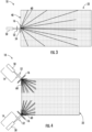
- optical element 16 is configured to increase an angular emission of light from the light source in a horizontal plane perpendicular to edge surface 40, and this increase is shown in the top view of FIG. 3 as the fan-shape of the light exiting optical element 16.
- optical element 16 increases the angular emission of light from the light source to at least 90 degrees in the plane perpendicular to the edge surface 40.
- optical element 16 is a lens, a diffractive optical element, a diffraction grating, a lens array, a lenticular array, a phase plate, or a combination of these elements that provide the angular increase discussed above.
- optical element 16 includes one or more circular, cylindrical, holographic, diffractive and/or aspheric lenses used to modify the beam shape and/or numerical aperture of light from light source 14. As will be discussed in more detail below, FIGS. 11-13 show specific embodiments of optical element 16.
- Light guide plate 22 is further configured to facilitate coupling of light exiting optical element 16 into light guide plate 22.
- vertical edge surface 40 includes a non-planar section (i.e., wherein sides are not substantially parallel), shown as semi-circular section 60, facing optical element 16.
- semi-circular section 60 is shaped such that light exiting optical element 16 is more effectively coupled into waveguide sheet 24 through the semi-circular section 60.
- the surface within section 60 is polished to improve coupling of light into light guide plate 22.
- transparent illumination system 10 may include multiple light sources 14 located around the perimeter of light guide plate 22.
- each light source 14 includes its own optical element 16 that faces its own non-planar surface section, shown as semi-circular sections 60, formed in edge surface 40.
- light sources 14 face the corners of light guide plate 22, and semi-circular sections 60 are located in the corners of light guide plate 22.
- light sources 14 with semi-circular sections 60 are located at three or four corners of light guide plate 22.
- portions of edges surface 40 outside of semi-circular section 60 may be coated with a reflective coating (specular tape or thin film) in order to reduce or prevent light leakage from the edge surface of light guide plate 22.
- waveguide sheet 24 includes an engineered pattern of light extraction features 70.
- LEFs 70 are substantially the same as LEFs 34 and act to scatter light towards interior direction 36.
- LEFs 70 are at a non-perpendicular angle to major surfaces 30 and 32 of sheet 24.
- LEFs 70 are at an angle between 0 and 30 degrees and more specifically between 10 and 30 degrees, relative to major surfaces 30 and 32 of sheet 24.
- LEFs 70 are positioned within sheet 24 in a pattern that produces uniform spatial illumination in the direction of arrow 36.
- LEFs 70 are positioned within sheet 24 in a pattern of light extractors produces a desired non-uniform spatial illumination pattern.
- Illumination system 100 is shown according to an exemplary embodiment. Illumination system 100 is substantially the same as illumination system 10 discussed above, except for the differences discussed herein.
- illumination system 100 includes a single layer light diffusing, light guide plate formed from waveguide sheet 24, as discussed above.
- no glass cladding layers 26 and 28 are coupled to sheet 24, and thus, polymer interlayer 20 is bonded directly to major surface 32 of waveguide sheet 24, and major surface 30 defines one of the exterior surfaces of the glass laminate article 12.
- waveguide sheet 24 is formed from a first glass material, and polymer interlayer 20 is an optical adhesive material.
- the first glass material has a first index of refraction and polymer interlayer 20 has a second index of refraction, and the first index of refraction is greater than the second index of refraction.
- a difference between the first index of refraction and the second index of refraction is between 0.01 and 0.2.
- refractive index of the glass material of waveguide sheet 24 is such that the refractive index is greater than the refractive index of polymer interlayer 20 to which it may be laminated. In various embodiments, this difference in refractive indices is >0.05, or preferably >0.1, and less than 0.2.
- waveguide sheet 24 includes an engineered pattern of light extraction features 70.
- LEFs 70 are substantially the same as LEFs 34 and act to scatter light towards interior direction 36. As discussed above, LEFs 70 are angled, and, as shown in FIG. 7 have increasing density away from light source 14.
- Illumination system 110 is shown according to an exemplary embodiment. Illumination system 110 is substantially the same as illumination system 100 discussed above, except for the differences discussed herein. Illumination system 110 includes a first light source 14 and a second light source 114. Light source 114 is substantially the same as light source 14 except that it is positioned along one of the other edges of waveguide sheet 24. In the specific embodiment shown, light source 14 and light source 114 are located on opposite edges of waveguide sheet 24. Light from light source 114 is fanned out via an additional optical element 116, that is similar to optical element 16. In this embodiment, LEFs 34 are arranged in a pattern/distribution within waveguide sheet 24 to account for the positioning of light sources 14 and 114.
- waveguide sheet 24 includes an engineered pattern of light extraction features 70.
- LEFs 70 are substantially the same as LEFs 34 shown in FIG. 8 and act to scatter light towards interior direction 36. As discussed above, LEFs 70 are angled, and, as shown in FIG. 7 have increasing density toward the center of waveguide sheet 24.
- optical element 16 is a Powell lens 120 that causes the light from the light source to increase its angle in the desired plane as shown by fan angle 122.
- fan angle 122 of any of the optical elements discussed herein may be 90 degrees or greater, and specifically may be less than 180 degrees.
- optical element 16 is one or more lenticular-array lens 124.
- optical element 16 is an engineered diffuser 126.
- vehicle 130 is shown equipped with one or more glass component having one or more of the transparent illumination system embodiments discussed herein.
- one or more of the transparent illumination systems discussed herein form part of illuminated automotive glass system.
- vehicle 130 includes an illuminated automotive glass system, shown as an illuminated sunroof 132.
- sunroof 132 is formed from glass laminate article 12 discussed herein, and the remaining components of the illumination system associated with article 12 are supported by vehicle body 134.
- glass laminate article 12 may include additional functional layers and/or functional coatings that may be utilized in an automotive glass application.
- glass laminate article 12 may include dynamic tinting films, and structural glass layer 18 may be a tinted or untinted soda lime glass layer.
- glass laminate article 12 may include a dynamic tint layer and in such embodiments, this layer could be a suspended particle device (SPED), a polymer dispersed liquid crystal (PLC.) or an organic electrochromic (EC).
- SPED suspended particle device
- PLC. polymer dispersed liquid crystal
- EC organic electrochromic
- cladding layer 26 prevents optical coupling of the dynamic tint layer to light guide plate 22.
- a pattern of light extraction features may be engineered into the central region of waveguide sheet 24.
- One approach is to scan a high-intensity pulsed laser to write sub-surface LEFs into the center of the light guide plate. In the laminated glass, this may be in the core layer (e.g., sheet 24 discussed above), but in some embodiments may extend into the cladding layers.
- the LEFs may be written in a single layer in the glass thickness, or multiple layers may be stacked up to increase the length.
- the properties of such features can be modified by controlling parameters such as the average laser power, laser intensity, laser pulse energy, laser pulse duration, the beam depth of focus (Rayleigh range), laser wavelength, and number of laser pulses.
- Lasers with wavelengths between 200 nm - 1500 nm can be used. Pulse lengths from 10-fs to 10 ns can be used.
- the beam spatial profile can be Gaussian or a beam profile that produces a quasi-non-diffracting beam such as a quasi-Bessel beam. This beam can be approximately circular or elliptical in shape to produce LEFs with a symmetric or asymmetric cross-sectional geometry.
- laser-induced LEFs are sub-surface features. If the features intersect the glass surface, the strength of the glass may be compromised and moisture in the environment may lead to spontaneous fracturing of the glass.
- the LEFs can be a relatively small modification of the local refractive index ⁇ n ⁇ 0.01, or can be as large as an air void with n ⁇ 1.0.
- Each LEF may have a cross-section for scattering and a scattering strength that can be used to design the gradient pattern of multiple LEFs across the light guide plate.
- the pattern is chosen to achieve a target luminance across the light guide plate. That luminance may be approximately uniform across the light guide plate. In other embodiments, it may be maximized in the center with a fall off towards the edges, but it may be designed to have a variety of other desired luminance distributions.
- This engineered pattern may be formed by changing the density (or spacing) of the LEFS, the cross-sectional size of the individual LEFs, the length of the LEFs, or the index change of the LEFs.
- Optical design tools such as LightTools, SPEOs or ZEMAX can be used to design the light extraction pattern.
- a uniform LEF pattern can be made in a test light guide plate.
- the exponential decay of the extracted light can be measured with an external camera or a scanning detector.
- the decay coefficient can be used in the design software to determine the desired pattern for the final light guide plate.
- the extraction pattern is designed in a similar manner.
- the LEFs may be at an angle to the output surface of the light guide plate. This can be accomplished by angling the laser beam that produces the LEF.
- the final angle of the LEF is determined by the input angle of the beam and the refraction within the glass. Achieving angles > 20° is difficult because of the impact of refraction.
- the beam shape might require modification in order to maintain the appropriate laser parameters for the formation of LEFs inside the glass.
- Higher internal angles would utilize prism structures that are index-matched and moved with the LEF-writing laser.
- the LEF angle can vary in relation to the local curvature.
- the final assembly can be tested for optical performance by using an imaging colorimeter or scanning spectroradiometer to evaluate the luminance pattern of the extracted light.
- the method consists of three main steps. First, illuminating the samples in dark field mode, typically via edge coupling, that can be coherent or non-coherent. Second, imaging the features with a microscope objective with a depth of field longer than the thickness of the substrate (taking into account optical thickness and incidence angle). Third, collecting the images with a CMOS or CCD camera. The resulting three-dimensional projection allows for quantification of light scattering properties of LEFs such as scattering intensity, location in the bulk of the substrate, existence of surface damage, LEF length, orientation, directionality, etc.
- a line-scan camera can also be used in combination with precise motion stages to collect images larger than the field of view of the camera and inspect larger samples in a short amount of time.
- the disclosure herein discusses the light guide plate and/or illumination system primarily in the context an automotive sunroof, other applications are contemplated.
- the designs and concepts discussed here are useful in any transparent illumination system application in which a light diffusing, light guide layer is located adjacent to high refractive index materials and/or is subject to surface degradation, such as dirt, water droplets, fingerprints, etc.
- the designs discussed herein improve waveguide function and/or light diffusion out of the transparent structure of the illuminating system.
- the transparent illumination devices discussed herein can be incorporated into a wide variety of architectural or aesthetic designs.
- the transparent illumination devices discussed herein provide signage for a window of a business.
- the transparent illumination devices discussed herein provide customizable wall color for a building such that the transparent illumination devices discussed herein can be illuminated in different colors.
- LEFs may include embedded structures of a material with higher melting temperature than surrounding glass material, crystals grown within the glass material, mechanically induced cracks in the glass material, etc., and LEFs may have a dimension (e.g., length, width, thickness, height) of at least 10 nm, such as at least 100 nm, such as no more than the thicknesses of the light diffusing, light guide layers disclosed herein.
Landscapes
- Physics & Mathematics (AREA)
- General Physics & Mathematics (AREA)
- Optics & Photonics (AREA)
- Engineering & Computer Science (AREA)
- Mechanical Engineering (AREA)
- Manufacturing & Machinery (AREA)
- Chemical & Material Sciences (AREA)
- Chemical Kinetics & Catalysis (AREA)
- General Chemical & Material Sciences (AREA)
- Thermal Sciences (AREA)
- Planar Illumination Modules (AREA)
Claims (7)
- Transparentes Beleuchtungssystem, umfassend:eine lichtstreuende Lichtleiterschicht (24), aufweisend:ein erstes Glasmaterial;eine erste Hauptfläche (30);eine zweite Hauptfläche (32) entgegengesetzt zur ersten Hauptfläche (30);eine kleine Randfläche (40), welche die erste Hauptfläche (30) mit der zweiten Hauptfläche (32) verbindet; undeine Vielzahl von Lichtauskopplungsmerkmalen (34);eine verstärkte strukturelle Glasschicht (18), die mit der Lichtleiterschicht (24) gekoppelt ist;eine Lichtquelle (14), die mit der kleinen Randfläche (40) der Lichtleiterschicht (24) optisch gekoppelt ist;ein optisches Element (16), das sich zwischen der Lichtquelle (14) und der kleinen Randfläche (40) der Lichtleiterschicht (24) befindet, wobei das optische Element (16) dafür ausgelegt ist, die Ausbreitung von Licht (54) von der Lichtquelle (14) in einer zur kleinen Randfläche (40) normalen Ebene zu ermöglichen; undeine Zwischenschicht (20, 26), die direkt mit der zweiten Hauptfläche (32) der Lichtleiterschicht (24) gekoppelt ist und sich zwischen der zweiten Hauptfläche (32) der Lichtleiterschicht (24) und der verstärkten strukturellen Glasschicht (18) befindet, wobei das erste Glasmaterial der Lichtleiterschicht (24) einen ersten Brechungsindex und die Zwischenschicht (20, 26) einen zweiten Brechungsindex hat, wobei der erste Brechungsindex größer als der zweite Brechungsindex ist und eine Differenz zwischen dem ersten Brechungsindex und zweiten Brechungsindex größer als 0,01 und kleiner als 0,2 ist,wobei Licht (54) von der Lichtquelle (14) durch die Lichtleiterschicht (24) über innere Totalreflexion übertragen wird und die Lichtauskopplungsmerkmale (34) dafür ausgelegt sind, Licht aus Lichtleiterschicht (24) heraus und durch die erste Hauptfläche zu leiten,dadurch gekennzeichnet, dassdie Lichtquelle (14) eine Laserdiode (50) aufweist und das optische Element (16) die winkelförmige Emission von Licht (54) von der Lichtquelle (14) auf mindestens 90 Grad in der Ebene senkrecht zur kleinen Randfläche (40) erhöht,wobei die Lichtquelle (14) einen Kollimator (52) aufweist, der sich zwischen der Laserdiode (50) und dem optischen Element (16) befindet, undwobei Licht (54) von der Lichtquelle (14), das aus dem Kollimator (52) austritt, eine winkelförmige Emission in einer Ebene parallel zur kleinen Randfläche (40) hat, die an der ersten und zweiten Hauptfläche (30, 32) kleiner als ein kritischer Winkel der Lichtleiterschicht (24) ist.
- Transparentes Beleuchtungssystem nach Anspruch 1, wobei die Lichtleiterschicht (24) eine numerische Apertur und die Laserdiode (50) eine numerische Apertur definiert, wobei die numerische Apertur der Lichtquelle (14) kleiner als die numerische Apertur der Lichtleiterschicht (24) ist.
- Transparentes Beleuchtungssystem nach einem der vorhergehenden Ansprüche, wobei die kleine Randfläche (40) einen nicht planaren Abschnitt aufweist, der dem optischen Element (16) so zugewandt ist, dass aus dem optischen Element (16) austretendes Licht durch den nicht planaren Abschnitt in die Lichtleiterschicht (24) eingekoppelt wird.
- Transparentes Beleuchtungssystem nach Anspruch 1, wobei die Zwischenschicht (20, 26) eine Schicht aus einem optischen Klebstoff (20) ist, der die verstärkte strukturelle Glasschicht (18) mit der Lichtleiterschicht (24) verklebt, oder eine Glasumhüllungsschicht (26) ist, die aus einem zweiten Glasmaterial gebildet ist, das sich vom ersten Glasmaterial der Lichtleiterschicht (24) unterscheidet.
- Transparentes Beleuchtungssystem nach Anspruch 4, darüber hinaus eine zweite Glasumhüllungsschicht (28) aufweisend, die mit der ersten Hauptfläche (30) der Lichtleiterschicht (24) gekoppelt ist, wobei die zweite Glasumhüllungsschicht (28) einen dritten Brechungsindex hat, wobei der erste Brechungsindex größer als der dritte Brechungsindex ist und eine Differenz zwischen dem ersten Brechungsindex und dritten Brechungsindex größer als 0,01 ist.
- Transparentes Beleuchtungssystem nach einem der vorhergehenden Ansprüche, wobei die Lichtleiterschicht (24) darüber hinaus aufweist:einen zentralen Bereich;einen ersten Außenbereich zwischen dem zentralen Bereich und der ersten Hauptfläche; undeinen zweiten Außenbereich zwischen dem zentralen Bereich und der zweiten Hauptfläche;wobei sich die Lichtauskopplungsmerkmale (34) in dem zentralen Bereich befinden und der erste und zweite Außenbereich im Wesentlichen frei von Lichtauskopplungsmerkmalen (34) ist.
- Transparentes Beleuchtungssystem nach Anspruch 6, wobei die Lichtauskopplungsmerkmale (34) laserinduzierte, unter der Oberfläche befindliche Merkmale sind, die einen Brechungsindex haben, der ein anderer ist als im benachbarten Bereich des ersten Glasmaterials.
Applications Claiming Priority (1)
| Application Number | Priority Date | Filing Date | Title |
|---|---|---|---|
| US202063046101P | 2020-06-30 | 2020-06-30 |
Publications (2)
| Publication Number | Publication Date |
|---|---|
| EP3932664A1 EP3932664A1 (de) | 2022-01-05 |
| EP3932664B1 true EP3932664B1 (de) | 2025-01-01 |
Family
ID=76708128
Family Applications (1)
| Application Number | Title | Priority Date | Filing Date |
|---|---|---|---|
| EP21182549.2A Active EP3932664B1 (de) | 2020-06-30 | 2021-06-29 | Lichtleiterplatte und transparentes beleuchtungssystem damit |
Country Status (2)
| Country | Link |
|---|---|
| US (1) | US11644609B2 (de) |
| EP (1) | EP3932664B1 (de) |
Families Citing this family (4)
| Publication number | Priority date | Publication date | Assignee | Title |
|---|---|---|---|---|
| FR3143716B1 (fr) * | 2022-12-16 | 2024-11-29 | Valeo Vision | Dispositif lumineux de véhicule comportant un guide de lumière muni d’une structure multicouche |
| US12155014B2 (en) * | 2023-03-02 | 2024-11-26 | Shining Victory International Holdings Co., Limited | Light-emitting apparatus for automobile sunroof |
| FR3151377B1 (fr) * | 2023-07-21 | 2025-08-01 | Valeo Vision | Dispositif lumineux de véhicule comportant une source de lumière blanche et un guide de lumière muni d’une structure multicouche permettant d’obtenir une couleur prédéterminée avec un circuit simplifié |
| FR3157862A1 (fr) * | 2023-12-27 | 2025-07-04 | Saint-Gobain Glass France | Matériau diffusant, vitrage lumineux et procédé de fabrication |
Citations (3)
| Publication number | Priority date | Publication date | Assignee | Title |
|---|---|---|---|---|
| US20100045894A1 (en) * | 2006-10-02 | 2010-02-25 | Tatsuo Itoh | Planar illumination apparatus and liquid crystal display apparatus using the same |
| US20110267833A1 (en) * | 2008-10-27 | 2011-11-03 | Saint-Gobain Glass France | Light-emitting diode module for a vehicle, and productions |
| US20150029754A1 (en) * | 2012-02-17 | 2015-01-29 | 3M Innovative Properties Company | Anamorphic light guide |
Family Cites Families (32)
| Publication number | Priority date | Publication date | Assignee | Title |
|---|---|---|---|---|
| JP2001171429A (ja) | 1999-12-15 | 2001-06-26 | Auto Network Gijutsu Kenkyusho:Kk | 車両天井の照明構造 |
| CN101511641B (zh) | 2006-08-01 | 2015-09-23 | 3M创新有限公司 | 照明装置 |
| JP2008174132A (ja) | 2007-01-19 | 2008-07-31 | Ichikoh Ind Ltd | 車両用室内照明装置 |
| FR2955539B1 (fr) * | 2010-01-26 | 2016-03-25 | Saint Gobain | Vitrage lumineux de vehicule, fabrications |
| FR2955915B1 (fr) | 2010-02-01 | 2012-03-09 | Saint Gobain | Vitrage multiple lumineux a diodes electroluminescentes |
| US20110249695A1 (en) * | 2010-04-13 | 2011-10-13 | Dmitri Vladislavovich Kuksenkov | Optically Pumped Laser |
| US8235460B2 (en) * | 2010-11-02 | 2012-08-07 | Nissan North America, Inc. | Vehicle window assembly |
| FR2970671B1 (fr) | 2011-01-21 | 2016-12-30 | Saint Gobain | Vitrage lumineux |
| FR2978379B1 (fr) * | 2011-07-29 | 2014-03-14 | Saint Gobain | Vitrage lumineux de vehicule, fabrication |
| DE102011112321B3 (de) | 2011-09-02 | 2012-08-02 | Audi Ag | Beleuchtungsvorrichtung zum Erzeugen eines Leuchtstreifens sowie Kraftwagen |
| US20150140301A1 (en) | 2012-06-08 | 2015-05-21 | Corning Incorporated | Laminated glass structures having high glass to polymer interlayer adhesion |
| BE1020715A3 (fr) | 2012-06-19 | 2014-04-01 | Agc Glass Europe | Toit vitre comportant des moyens d'eclairage. |
| US20140085924A1 (en) * | 2012-09-27 | 2014-03-27 | Osram Sylvania Inc. | Edge-lit light panel |
| DE102012109900B4 (de) * | 2012-10-17 | 2015-10-15 | Bayerische Motoren Werke Aktiengesellschaft | Fahrzeugverglasung |
| FR3017332B1 (fr) | 2014-02-10 | 2016-02-19 | Saint Gobain | Vitrage lumineux avec isolateur optique. |
| FR3023213B1 (fr) * | 2014-07-03 | 2016-07-29 | Saint Gobain | Ensemble vitre lumineux. |
| US9517721B2 (en) | 2014-08-22 | 2016-12-13 | Guardian Industries Corp. | Vehicle sunroof with switchable glazing and side-firing light emitting diodes |
| FR3034500A1 (fr) * | 2015-04-03 | 2016-10-07 | Saint Gobain | Vitrage lumineux de vehicule automobile et vehicule automobile avec un tel vitrage |
| FR3034501A1 (fr) * | 2015-04-03 | 2016-10-07 | Saint Gobain | Vitrage lumineux pour batiment, mobilier, vehicule de transport en commun |
| KR101917220B1 (ko) * | 2015-12-29 | 2018-11-12 | 레이비전스마트라이팅(주) | 광확산용 패널을 이용한 발광유리 |
| US10150352B2 (en) * | 2016-02-11 | 2018-12-11 | Ford Global Technologies, Llc | Illuminated window assemblies having light-diffusing elements |
| CN205523597U (zh) | 2016-04-20 | 2016-08-31 | 上海亨诺塑料制品有限公司 | 一种汽车天窗玻璃总成 |
| CN109328313A (zh) | 2016-04-27 | 2019-02-12 | 巴斯夫欧洲公司 | 层压发光器件 |
| US10099606B2 (en) * | 2016-06-02 | 2018-10-16 | Ford Global Technologies, Llc | Dome light assemblies and units that produce natural and courtesy light patterns |
| CN205768560U (zh) | 2016-06-26 | 2016-12-07 | 天津中科先进技术研究院有限公司 | 一种多功能汽车天窗 |
| US9845047B1 (en) * | 2016-08-08 | 2017-12-19 | Ford Global Technologies, Llc | Light system |
| US10618462B2 (en) * | 2016-11-01 | 2020-04-14 | Custom Glass Solutions, Llc | Encapsulation-embedded exterior-facing light set for vehicles, and/or method of making the same |
| JP6659014B2 (ja) | 2016-11-02 | 2020-03-04 | 河西工業株式会社 | 照明構造 |
| US10053006B1 (en) * | 2017-01-31 | 2018-08-21 | Ford Global Technologies, Llc | Illuminated assembly |
| EP3837579B1 (de) * | 2018-08-13 | 2024-05-22 | LEIA Inc. | Gitterkollimator, hintergrundbeleuchtungssystem und verfahren unter verwendung einer lichtreflektierenden lichtquelle |
| WO2020123539A1 (en) * | 2018-12-11 | 2020-06-18 | Flex Lighting Ii, Llc | Front illumination lightguide with a diffusely reflective release liner |
| WO2020247233A1 (en) | 2019-06-04 | 2020-12-10 | Corning Incorporated | Window with light pipe and light-scattering structures |
-
2021
- 2021-06-29 EP EP21182549.2A patent/EP3932664B1/de active Active
- 2021-06-30 US US17/363,655 patent/US11644609B2/en active Active
Patent Citations (3)
| Publication number | Priority date | Publication date | Assignee | Title |
|---|---|---|---|---|
| US20100045894A1 (en) * | 2006-10-02 | 2010-02-25 | Tatsuo Itoh | Planar illumination apparatus and liquid crystal display apparatus using the same |
| US20110267833A1 (en) * | 2008-10-27 | 2011-11-03 | Saint-Gobain Glass France | Light-emitting diode module for a vehicle, and productions |
| US20150029754A1 (en) * | 2012-02-17 | 2015-01-29 | 3M Innovative Properties Company | Anamorphic light guide |
Also Published As
| Publication number | Publication date |
|---|---|
| EP3932664A1 (de) | 2022-01-05 |
| US20210405278A1 (en) | 2021-12-30 |
| US11644609B2 (en) | 2023-05-09 |
Similar Documents
| Publication | Publication Date | Title |
|---|---|---|
| EP3932664B1 (de) | Lichtleiterplatte und transparentes beleuchtungssystem damit | |
| KR102671591B1 (ko) | 광학 장치 | |
| TWI539188B (zh) | 用於提供改良之顯示部件的裝置及方法 | |
| KR20230003212A (ko) | 타일링된 구성요소들을 갖는 디스플레이 장치 | |
| US11022745B2 (en) | Microstructured and patterned light guide plates and devices comprising the same | |
| US10429553B2 (en) | Optical assembly having microlouvers | |
| KR102450088B1 (ko) | 미세 구조화된 도광판 및 그를 포함하는 장치 | |
| TWI772501B (zh) | 用於直接發光的背光的多層反射器 | |
| US20230083188A1 (en) | Apparatus for removing at least one portion of at least one coating system presenting a multi-glazed window and associated method | |
| KR20180127392A (ko) | 광학체, 창재 및 롤 커튼 | |
| US11106125B2 (en) | Transparent screen, image projection laminated plate, image display system, and method for producing transparent screen | |
| CN110249176A (zh) | 包含光学操控特征体的光导组合件 | |
| US20230296823A1 (en) | Light incoupling tape, related method and uses | |
| TW202028826A (zh) | 導光組件、背光模組及顯示設備 | |
| CN110325792A (zh) | 包含集成背光单元和显示面板的装置 | |
| JP7428987B2 (ja) | 異方性光学フィルムを用いた導光積層体、及び、それを用いた表示装置用面状照明装置 | |
| US11086052B2 (en) | Optical isolation element | |
| WO2025017452A1 (en) | Luminois laminated glazing with enhanced solar and ambient light performance | |
| CN112771441B (zh) | 使用了各向异性光学膜的导光层叠体及使用了该导光层叠体的显示装置用面状照明装置 | |
| CN121187000A (zh) | 虚像显示装置与交通载具显示系统 | |
| KR20130074538A (ko) | 광학 유닛 |
Legal Events
| Date | Code | Title | Description |
|---|---|---|---|
| PUAI | Public reference made under article 153(3) epc to a published international application that has entered the european phase |
Free format text: ORIGINAL CODE: 0009012 |
|
| STAA | Information on the status of an ep patent application or granted ep patent |
Free format text: STATUS: THE APPLICATION HAS BEEN PUBLISHED |
|
| AK | Designated contracting states |
Kind code of ref document: A1 Designated state(s): AL AT BE BG CH CY CZ DE DK EE ES FI FR GB GR HR HU IE IS IT LI LT LU LV MC MK MT NL NO PL PT RO RS SE SI SK SM TR |
|
| B565 | Issuance of search results under rule 164(2) epc |
Effective date: 20211203 |
|
| STAA | Information on the status of an ep patent application or granted ep patent |
Free format text: STATUS: REQUEST FOR EXAMINATION WAS MADE |
|
| 17P | Request for examination filed |
Effective date: 20220623 |
|
| RBV | Designated contracting states (corrected) |
Designated state(s): AL AT BE BG CH CY CZ DE DK EE ES FI FR GB GR HR HU IE IS IT LI LT LU LV MC MK MT NL NO PL PT RO RS SE SI SK SM TR |
|
| STAA | Information on the status of an ep patent application or granted ep patent |
Free format text: STATUS: EXAMINATION IS IN PROGRESS |
|
| 17Q | First examination report despatched |
Effective date: 20230331 |
|
| GRAP | Despatch of communication of intention to grant a patent |
Free format text: ORIGINAL CODE: EPIDOSNIGR1 |
|
| STAA | Information on the status of an ep patent application or granted ep patent |
Free format text: STATUS: GRANT OF PATENT IS INTENDED |
|
| INTG | Intention to grant announced |
Effective date: 20240906 |
|
| P01 | Opt-out of the competence of the unified patent court (upc) registered |
Free format text: CASE NUMBER: APP_53857/2024 Effective date: 20240930 |
|
| GRAS | Grant fee paid |
Free format text: ORIGINAL CODE: EPIDOSNIGR3 |
|
| GRAA | (expected) grant |
Free format text: ORIGINAL CODE: 0009210 |
|
| STAA | Information on the status of an ep patent application or granted ep patent |
Free format text: STATUS: THE PATENT HAS BEEN GRANTED |
|
| AK | Designated contracting states |
Kind code of ref document: B1 Designated state(s): AL AT BE BG CH CY CZ DE DK EE ES FI FR GB GR HR HU IE IS IT LI LT LU LV MC MK MT NL NO PL PT RO RS SE SI SK SM TR |
|
| REG | Reference to a national code |
Ref country code: GB Ref legal event code: FG4D |
|
| REG | Reference to a national code |
Ref country code: DE Ref legal event code: R096 Ref document number: 602021024117 Country of ref document: DE |
|
| REG | Reference to a national code |
Ref country code: CH Ref legal event code: EP |
|
| REG | Reference to a national code |
Ref country code: IE Ref legal event code: FG4D |
|
| REG | Reference to a national code |
Ref country code: LT Ref legal event code: MG9D |
|
| REG | Reference to a national code |
Ref country code: NL Ref legal event code: MP Effective date: 20250101 |
|
| REG | Reference to a national code |
Ref country code: AT Ref legal event code: MK05 Ref document number: 1755836 Country of ref document: AT Kind code of ref document: T Effective date: 20250101 |
|
| PG25 | Lapsed in a contracting state [announced via postgrant information from national office to epo] |
Ref country code: NL Free format text: LAPSE BECAUSE OF FAILURE TO SUBMIT A TRANSLATION OF THE DESCRIPTION OR TO PAY THE FEE WITHIN THE PRESCRIBED TIME-LIMIT Effective date: 20250101 |
|
| PG25 | Lapsed in a contracting state [announced via postgrant information from national office to epo] |
Ref country code: FI Free format text: LAPSE BECAUSE OF FAILURE TO SUBMIT A TRANSLATION OF THE DESCRIPTION OR TO PAY THE FEE WITHIN THE PRESCRIBED TIME-LIMIT Effective date: 20250101 |
|
| PG25 | Lapsed in a contracting state [announced via postgrant information from national office to epo] |
Ref country code: PL Free format text: LAPSE BECAUSE OF FAILURE TO SUBMIT A TRANSLATION OF THE DESCRIPTION OR TO PAY THE FEE WITHIN THE PRESCRIBED TIME-LIMIT Effective date: 20250101 |
|
| PGFP | Annual fee paid to national office [announced via postgrant information from national office to epo] |
Ref country code: DE Payment date: 20250509 Year of fee payment: 5 |
|
| PG25 | Lapsed in a contracting state [announced via postgrant information from national office to epo] |
Ref country code: ES Free format text: LAPSE BECAUSE OF FAILURE TO SUBMIT A TRANSLATION OF THE DESCRIPTION OR TO PAY THE FEE WITHIN THE PRESCRIBED TIME-LIMIT Effective date: 20250101 |
|
| PG25 | Lapsed in a contracting state [announced via postgrant information from national office to epo] |
Ref country code: NO Free format text: LAPSE BECAUSE OF FAILURE TO SUBMIT A TRANSLATION OF THE DESCRIPTION OR TO PAY THE FEE WITHIN THE PRESCRIBED TIME-LIMIT Effective date: 20250401 Ref country code: IS Free format text: LAPSE BECAUSE OF FAILURE TO SUBMIT A TRANSLATION OF THE DESCRIPTION OR TO PAY THE FEE WITHIN THE PRESCRIBED TIME-LIMIT Effective date: 20250501 |
|
| PG25 | Lapsed in a contracting state [announced via postgrant information from national office to epo] |
Ref country code: HR Free format text: LAPSE BECAUSE OF FAILURE TO SUBMIT A TRANSLATION OF THE DESCRIPTION OR TO PAY THE FEE WITHIN THE PRESCRIBED TIME-LIMIT Effective date: 20250101 |
|
| PG25 | Lapsed in a contracting state [announced via postgrant information from national office to epo] |
Ref country code: PT Free format text: LAPSE BECAUSE OF FAILURE TO SUBMIT A TRANSLATION OF THE DESCRIPTION OR TO PAY THE FEE WITHIN THE PRESCRIBED TIME-LIMIT Effective date: 20250502 Ref country code: LV Free format text: LAPSE BECAUSE OF FAILURE TO SUBMIT A TRANSLATION OF THE DESCRIPTION OR TO PAY THE FEE WITHIN THE PRESCRIBED TIME-LIMIT Effective date: 20250101 |
|
| PGFP | Annual fee paid to national office [announced via postgrant information from national office to epo] |
Ref country code: FR Payment date: 20250512 Year of fee payment: 5 |
|
| PG25 | Lapsed in a contracting state [announced via postgrant information from national office to epo] |
Ref country code: GR Free format text: LAPSE BECAUSE OF FAILURE TO SUBMIT A TRANSLATION OF THE DESCRIPTION OR TO PAY THE FEE WITHIN THE PRESCRIBED TIME-LIMIT Effective date: 20250402 Ref country code: BG Free format text: LAPSE BECAUSE OF FAILURE TO SUBMIT A TRANSLATION OF THE DESCRIPTION OR TO PAY THE FEE WITHIN THE PRESCRIBED TIME-LIMIT Effective date: 20250101 |
|
| PG25 | Lapsed in a contracting state [announced via postgrant information from national office to epo] |
Ref country code: AT Free format text: LAPSE BECAUSE OF FAILURE TO SUBMIT A TRANSLATION OF THE DESCRIPTION OR TO PAY THE FEE WITHIN THE PRESCRIBED TIME-LIMIT Effective date: 20250101 |
|
| PG25 | Lapsed in a contracting state [announced via postgrant information from national office to epo] |
Ref country code: CZ Free format text: LAPSE BECAUSE OF FAILURE TO SUBMIT A TRANSLATION OF THE DESCRIPTION OR TO PAY THE FEE WITHIN THE PRESCRIBED TIME-LIMIT Effective date: 20250101 |
|
| PG25 | Lapsed in a contracting state [announced via postgrant information from national office to epo] |
Ref country code: SE Free format text: LAPSE BECAUSE OF FAILURE TO SUBMIT A TRANSLATION OF THE DESCRIPTION OR TO PAY THE FEE WITHIN THE PRESCRIBED TIME-LIMIT Effective date: 20250101 |
|
| REG | Reference to a national code |
Ref country code: DE Ref legal event code: R097 Ref document number: 602021024117 Country of ref document: DE |
|
| PG25 | Lapsed in a contracting state [announced via postgrant information from national office to epo] |
Ref country code: SM Free format text: LAPSE BECAUSE OF FAILURE TO SUBMIT A TRANSLATION OF THE DESCRIPTION OR TO PAY THE FEE WITHIN THE PRESCRIBED TIME-LIMIT Effective date: 20250101 |
|
| PG25 | Lapsed in a contracting state [announced via postgrant information from national office to epo] |
Ref country code: DK Free format text: LAPSE BECAUSE OF FAILURE TO SUBMIT A TRANSLATION OF THE DESCRIPTION OR TO PAY THE FEE WITHIN THE PRESCRIBED TIME-LIMIT Effective date: 20250101 |
|
| PG25 | Lapsed in a contracting state [announced via postgrant information from national office to epo] |
Ref country code: IT Free format text: LAPSE BECAUSE OF FAILURE TO SUBMIT A TRANSLATION OF THE DESCRIPTION OR TO PAY THE FEE WITHIN THE PRESCRIBED TIME-LIMIT Effective date: 20250101 |
|
| PG25 | Lapsed in a contracting state [announced via postgrant information from national office to epo] |
Ref country code: EE Free format text: LAPSE BECAUSE OF FAILURE TO SUBMIT A TRANSLATION OF THE DESCRIPTION OR TO PAY THE FEE WITHIN THE PRESCRIBED TIME-LIMIT Effective date: 20250101 |
|
| PG25 | Lapsed in a contracting state [announced via postgrant information from national office to epo] |
Ref country code: RO Free format text: LAPSE BECAUSE OF FAILURE TO SUBMIT A TRANSLATION OF THE DESCRIPTION OR TO PAY THE FEE WITHIN THE PRESCRIBED TIME-LIMIT Effective date: 20250101 |
|
| PG25 | Lapsed in a contracting state [announced via postgrant information from national office to epo] |
Ref country code: SK Free format text: LAPSE BECAUSE OF FAILURE TO SUBMIT A TRANSLATION OF THE DESCRIPTION OR TO PAY THE FEE WITHIN THE PRESCRIBED TIME-LIMIT Effective date: 20250101 |
|
| PLBE | No opposition filed within time limit |
Free format text: ORIGINAL CODE: 0009261 |
|
| STAA | Information on the status of an ep patent application or granted ep patent |
Free format text: STATUS: NO OPPOSITION FILED WITHIN TIME LIMIT |
|
| REG | Reference to a national code |
Ref country code: CH Ref legal event code: L10 Free format text: ST27 STATUS EVENT CODE: U-0-0-L10-L00 (AS PROVIDED BY THE NATIONAL OFFICE) Effective date: 20251112 |
|
| 26N | No opposition filed |
Effective date: 20251002 |
|
| REG | Reference to a national code |
Ref country code: CH Ref legal event code: H13 Free format text: ST27 STATUS EVENT CODE: U-0-0-H10-H13 (AS PROVIDED BY THE NATIONAL OFFICE) Effective date: 20260127 |
|
| PG25 | Lapsed in a contracting state [announced via postgrant information from national office to epo] |
Ref country code: MC Free format text: LAPSE BECAUSE OF FAILURE TO SUBMIT A TRANSLATION OF THE DESCRIPTION OR TO PAY THE FEE WITHIN THE PRESCRIBED TIME-LIMIT Effective date: 20250101 |
|
| PG25 | Lapsed in a contracting state [announced via postgrant information from national office to epo] |
Ref country code: LU Free format text: LAPSE BECAUSE OF NON-PAYMENT OF DUE FEES Effective date: 20250629 |
|
| GBPC | Gb: european patent ceased through non-payment of renewal fee |
Effective date: 20250629 |
|
| REG | Reference to a national code |
Ref country code: BE Ref legal event code: MM Effective date: 20250630 |
|
| PG25 | Lapsed in a contracting state [announced via postgrant information from national office to epo] |
Ref country code: GB Free format text: LAPSE BECAUSE OF NON-PAYMENT OF DUE FEES Effective date: 20250629 |
|
| PG25 | Lapsed in a contracting state [announced via postgrant information from national office to epo] |
Ref country code: IE Free format text: LAPSE BECAUSE OF NON-PAYMENT OF DUE FEES Effective date: 20250629 |
|
| PG25 | Lapsed in a contracting state [announced via postgrant information from national office to epo] |
Ref country code: BE Free format text: LAPSE BECAUSE OF NON-PAYMENT OF DUE FEES Effective date: 20250630 |