EP3933067A1 - Procédé de fabrication d'un revêtement, revêtement, composant doté d'un revêtement - Google Patents
Procédé de fabrication d'un revêtement, revêtement, composant doté d'un revêtement Download PDFInfo
- Publication number
- EP3933067A1 EP3933067A1 EP20184029.5A EP20184029A EP3933067A1 EP 3933067 A1 EP3933067 A1 EP 3933067A1 EP 20184029 A EP20184029 A EP 20184029A EP 3933067 A1 EP3933067 A1 EP 3933067A1
- Authority
- EP
- European Patent Office
- Prior art keywords
- powder
- coating
- particles
- layer
- component
- Prior art date
- Legal status (The legal status is an assumption and is not a legal conclusion. Google has not performed a legal analysis and makes no representation as to the accuracy of the status listed.)
- Pending
Links
Images

Classifications
-
- C—CHEMISTRY; METALLURGY
- C23—COATING METALLIC MATERIAL; COATING MATERIAL WITH METALLIC MATERIAL; CHEMICAL SURFACE TREATMENT; DIFFUSION TREATMENT OF METALLIC MATERIAL; COATING BY VACUUM EVAPORATION, BY SPUTTERING, BY ION IMPLANTATION OR BY CHEMICAL VAPOUR DEPOSITION, IN GENERAL; INHIBITING CORROSION OF METALLIC MATERIAL OR INCRUSTATION IN GENERAL
- C23C—COATING METALLIC MATERIAL; COATING MATERIAL WITH METALLIC MATERIAL; SURFACE TREATMENT OF METALLIC MATERIAL BY DIFFUSION INTO THE SURFACE, BY CHEMICAL CONVERSION OR SUBSTITUTION; COATING BY VACUUM EVAPORATION, BY SPUTTERING, BY ION IMPLANTATION OR BY CHEMICAL VAPOUR DEPOSITION, IN GENERAL
- C23C24/00—Coating starting from inorganic powder
- C23C24/02—Coating starting from inorganic powder by application of pressure only
- C23C24/04—Impact or kinetic deposition of particles
Definitions
- the invention relates to a method for producing a coating, a coating and a component with a coating.
- a tooth contour of the edge layer should have a high load-bearing capacity, and an inner circumference of the edge layer should have a certain toughness. So far, this has been achieved by means of case hardening.
- Case hardening is a process for surface hardening, in particular for hardening the surface layer.
- the method comprises in particular the following steps: carburizing, hardening and tempering of a workpiece, advantageously comprising case-hardening steel.
- the surface layer of the workpiece is enriched with carbon.
- a carbon profile is established which typically has a progression of the carbon content (also: C content) that decreases with increasing distance from the edge to the core.
- Hardening and tempering are carried out after the carburization. This sets the edge hardness and case hardening depth.
- case hardening has some disadvantages, such as a long process time.
- An object on which the invention is based can consequently be seen in improving the surface hardening of gearwheels and reducing a process time.
- a method for producing a coating wherein the coating comprises at least two layers, on a base body, wherein a plurality of particles is accelerated in such a way that the particles adhere to the base body when they strike a surface of the base body, wherein in a first coating phase the A plurality of particles has at least one first powder, a first layer being formed in the first coating phase, the plurality of particles having at least the first powder and at least one second powder in a second coating phase, a second layer being formed in the second coating phase .
- the base body is preferably a component, in particular a gear.
- the invention is particularly suitable for gears in transmissions with a high power density. These include gearboxes for wind turbines, conveyor belts and the automotive sector. Other areas of application are also conceivable.
- the coating is preferably an edge layer.
- the plurality of particles can also be referred to as a particle quantity. It is preferably a granular material.
- a method in which a plurality of particles is accelerated in such a way that the particles adhere to the base body when they strike a surface of a base body is, for example, cold gas spraying.
- the coating is achieved by converting the high kinetic energy of the accelerated particles.
- Cold gas spraying (also called cold spray) is a process in the field of thermal spraying. This method is advantageous because a spray material is neither melted nor melted and as a result, there is little thermal influence on the layer and carrier material
- a process gas e.g. B. nitrogen or helium
- a spray gun at high pressure (preferably 30 bar to 50 bar) and heated in the gun housing to a temperature which is preferably between 800 ° C and 1100 ° C.
- a subsequent expansion of the heated and highly stressed gas in a convergent-divergent nozzle to ambient pressure has the consequence that the process gas accelerates to supersonic speed and cools down to temperatures of approx. Below 100 ° C.
- Granular material in particular powder, is injected by means of a conveying unit and a preferably similar carrier gas in the convergent area of the nozzle and accelerated in the main gas flow to particle speeds of advantageously 900 m / s to 1200 m / s).
- Powder particles strike a preferably untreated component surface in an advantageously strongly focused spray jet.
- the substrate i.e. the component surface
- a deformation of the powder particles themselves as a result of which a firmly adhering, dense and low-oxide layer is formed.
- the high kinetic energy of the powder particles and the associated high degree of deformation upon impact on the component enable the production of homogeneous and very dense layers with a variable layer thickness of 1 ⁇ m up to 20 cm.
- metallic layers are preferably produced whose physical and chemical properties hardly differ from those of the component's starting material.
- a mixing ratio of the first powder and the second powder in the second coating phase is changed by a mixing unit such that at the beginning of the second coating phase a number of particles of the first powder is greater than a number of particles of the second powder and am At the end of the second coating phase, the number of particles in the first powder is smaller than the number of particles in the second powder.
- the amount of the first powder is reduced, the amount of the second powder is increased.
- the first powder has a first carbon content, the second powder having a second carbon content, the second carbon content being higher than the first carbon content.
- the first powder has steel particles, preferably case-hardened steel particles.
- the second powder has steel particles, preferably case-hardened steel particles.
- Gear steel particles and their alloys are particularly suitable as steel particles.
- Carbon is advantageously dissolved in the steel particles in a desired dosage.
- carbon particles are added in a desired dosage.
- the plurality of particles in a third coating phase has at least one second powder, a third layer being formed in the third coating phase, the plurality of particles having at least the second powder and at least one third powder in a fourth coating phase, a fourth layer being formed in the fourth coating phase.
- Any number of layers can be formed in this way. This depends, for example, on an overall size of the component.
- the object set above is also achieved by means of a coating, in particular produced according to the one described A method comprising at least two layers, a first layer having a first mass fraction of carbon, a second layer having a second mass fraction of carbon.
- a transition between the first layer and the second layer is fluid.
- a transition between the first layer and the second layer is formed at least essentially linearly.
- the component is designed as a gear.
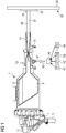
- FIG 1 shows an exemplary device 1 for performing the method according to the invention.
- the Figure 1 shows a heated high pressure chamber 3 and a heating element 5.
- a process gas 7, preferably nitrogen or helium, is fed into the device 1, advantageously designed as a spray gun, at high pressure and heated to a temperature between 800 ° C and 1100 ° C.
- the device 1 shows a pressure measurement 11, the heating element 5 and the heated high-pressure chamber 3.
- the device 1 also has a power supply 9.
- the figure shows a nozzle 14 in which the heated and highly stressed process gas 7 expands advantageously to ambient pressure.
- the process gas 7 is accelerated to supersonic speed by the expansion and cooled to temperatures of less than 100 ° C. This is achieved, among other things, with nozzle cooling 15.
- the carrier gas 16 preferably being of the same type as the process gas 7, particles 40, in particular powder, are injected. This is advantageously achieved in the convergent area of the nozzle 14.
- the particles 40 are accelerated to speeds of preferably 900 m / s to 1200 m / s.
- the figure shows a mixing unit 19 in which a desired powder mixture is obtained from the powders P1, P2, P3, ..., Pn.
- the first powder P1 is stored in a chamber K1, for example.
- the second powder P2 is stored in a chamber K2, for example.
- the third powder P3 is stored in a chamber K3, for example.
- a spray jet 21 leads to a particle impact 20 on a surface 23 of a component 24.
- a coating 20 is formed.
- the coating 20 has a first layer 22 in the figure.
- the finished coating advantageously has at least two layers.
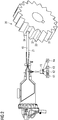
- FIG 2 shows a coating of a gear 30 by means of the in FIG 1 1.
- the gear wheel 30 has a tooth flank 31, a tooth root 32, a tooth head 33 and a head surface 34.
- an edge layer is preferably produced on the gear wheel 30, in particular on the tooth flank 31 and the tooth root 32.
- layers of materials of the same alloy but with different carbon contents are applied one after the other.
- the carbon content preferably decreases from an outer circumference to an inner circumference (in other words: in the case of the profile, from the outside to the inside). This is achieved by mixing the different powders.
- the gear 30 is, for example, first sprayed with powder P3 from chamber K3, then from a mixture of powder P2 from chamber K2 and powder P3, then with powder P2, then from a mixture of powder P1 from chamber K1 and powder P2 and finally with Powder P1.
- the mixing unit 19 advantageously removes so much powder from the individual chambers Kl, ..., Kn that a smooth transition from powder P2 to powder P1 or from powder P3 to powder P2 is achieved. However, an abrupt transition is also conceivable.
- FIG 3 shows a typical structure of a coating 100.
- the figure shows the width b on the X axis and a profile depth t of the coating on the Y axis.
- a layer P2 On an outer circumference A of the coating there is a layer with powder P1, then a layer P2 then follows the arrow 50, then a layer P3, then a layer P4 ... up to a layer Pn.
- the layer P1 advantageously has the greatest carbon content
- the layer Pn on an inner circumference I advantageously has the lowest carbon content.
- the carbon content of the coating decreases along the arrow 50.
- each layer P1, ..., Pn is directly related to a hardness of a layer P1, ..., Pn.
- FIG 4 shows a diagram of the carbon content with the profile depth t on the X-axis and the carbon content C on the Y-axis.
- the figure shows the course of the individual layers P1, ..., Pn, which were caused by the various powders or powder mixtures.
- the figure shows a course of the C content, starting at the outer circumference A with P1 and thus with a very high carbon content.
- a mixture of P1 and P2 a mixing ratio advantageously running at least essentially smoothly in the direction of the profile depth, to the inner circumference I of the coating.
- a layer comprising powder P2 then a mixture of P2 and P3, then a layer of P3.
- the figure shows a stepped profile of the carbon content C with rounded corners.
- the rounded corners mark the flowing transition.
- the fineness of the gradation can be influenced by the fineness when mixing powders with different C contents. In this way, a typical C-profile for today's case hardening can be reproduced.
- One step corresponds, for example, to a layer thickness of 10 to 200 ⁇ m. However, this depends on a component size.
- the number of layers also depends on the size of the component. The following applies advantageously: the larger the component, the thicker the layer.
- a linear course is also conceivable.
- a hardness h corresponds to the C content.
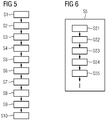
- FIG 5 shows a possible overall sequence of the process for producing the coating.
- process gas is fed into a spray gun under pressure.
- step S2 the gun housing is heated or the process gas in the gun housing is heated.
- step S3 the process gas expands in the nozzle.
- a mixing ratio of the powder to be injected is brought about.
- the process step S5 is carried out in the following FIG 6 explained in more detail.
- a method step S6 the powder is injected into the main gas jet, as a result of which the powder is accelerated in a method step S7.
- step S8 the particles impinge, for example on a surface of a component.
- a method step S9 the substrate of the component, that is to say the component material, and the particles themselves are deformed.
- a fixed layer is reached in a method step S10.
- the solid layer is created by deformation of the substrate and the particles when the particles hit due to their high kinetic energy.
- magnesium, aluminum, titanium, nickel, copper, tantalum, niobium, silver and / or gold are suitable as coating materials which are sprayed onto the base body or components as a powder.
- alloys comprising nickel-chromium, bronze, aluminum alloys, titanium alloys and MCrAlY alloys are also conceivable.
- Mixtures of materials are also conceivable, which include metal and ceramic, for example, as well as other composite materials.
- Steel, in particular case-hardened steel, can also be sprayed onto components as a powder.
- the base bodies or components are advantageously designed in such a way that they comprise metal, plastic, glass and / or ceramics.
- other coating materials are also conceivable.
- Other carrier materials for the components are also conceivable.
- Inexpensive materials can be used for the base body.
- FIG 6 shows method step S5 FIG 5 in detail. As already explained, the mixing ratio of the powder is brought about in method step S5.
- a method step S51 only powder 3 from chamber K3 is used in order to inject it in method step S6.
- step S52 a mixture of powder 3 and powder 2 is brought about.
- a method step S53 only powder 2 is used.
- powder 1 and powder 3 are used.
- powder 1 is used. Powder 1 thus forms the layer on the outer circumference of the coating and powder 3 the layer on the inner circumference, which rests directly on the base body. Powder 1 preferably has the highest carbon content and powder 3 the lowest carbon content.
- the powder mixture in method step S52 and method step S54 can also be such that there is an abrupt transition from one powder to the other powder.
- a flowing, in particular at least essentially linear, transition between the powders is advantageous. This means that a powder content of one powder slowly decreases, while the powder content of the other powder increases to the same extent.
- the number of different powders is purely by way of example, more than three powders can be used, but also fewer.
- the invention offers the advantage that the C-profile typical of today's case hardening is reproduced in a short time.
Landscapes
- Chemical & Material Sciences (AREA)
- Chemical Kinetics & Catalysis (AREA)
- Engineering & Computer Science (AREA)
- Materials Engineering (AREA)
- Mechanical Engineering (AREA)
- Metallurgy (AREA)
- Organic Chemistry (AREA)
- Application Of Or Painting With Fluid Materials (AREA)
Priority Applications (1)
| Application Number | Priority Date | Filing Date | Title |
|---|---|---|---|
| EP20184029.5A EP3933067A1 (fr) | 2020-07-03 | 2020-07-03 | Procédé de fabrication d'un revêtement, revêtement, composant doté d'un revêtement |
Applications Claiming Priority (1)
| Application Number | Priority Date | Filing Date | Title |
|---|---|---|---|
| EP20184029.5A EP3933067A1 (fr) | 2020-07-03 | 2020-07-03 | Procédé de fabrication d'un revêtement, revêtement, composant doté d'un revêtement |
Publications (1)
| Publication Number | Publication Date |
|---|---|
| EP3933067A1 true EP3933067A1 (fr) | 2022-01-05 |
Family
ID=71514962
Family Applications (1)
| Application Number | Title | Priority Date | Filing Date |
|---|---|---|---|
| EP20184029.5A Pending EP3933067A1 (fr) | 2020-07-03 | 2020-07-03 | Procédé de fabrication d'un revêtement, revêtement, composant doté d'un revêtement |
Country Status (1)
| Country | Link |
|---|---|
| EP (1) | EP3933067A1 (fr) |
Cited By (1)
| Publication number | Priority date | Publication date | Assignee | Title |
|---|---|---|---|---|
| EP4667760A1 (fr) | 2024-06-19 | 2025-12-24 | Flender GmbH | Procédé de fabrication d'un composant de palier, composant de palier et axe du porte-satellites |
Citations (6)
| Publication number | Priority date | Publication date | Assignee | Title |
|---|---|---|---|---|
| WO1999051790A1 (fr) * | 1998-04-08 | 1999-10-14 | Caterpillar Inc. | Procede d'applicaiton de revetement a base de materiau a gradient fonctionnel sur un composant afin d'ameliorer ses proprietes d'emploi |
| US20030126800A1 (en) * | 2001-12-05 | 2003-07-10 | Siemens Westinghouse Power Corporation | Mixed powder deposition of components for wear, erosion and abrasion resistant applications |
| EP1712657A2 (fr) * | 2005-04-14 | 2006-10-18 | United Technologies Corporation | Methode de fabrication et dispositif pour fabriquer un materiauà gradient fonctionnel par pulvérisation à froid |
| EP2781622A1 (fr) * | 2013-03-21 | 2014-09-24 | Siemens Aktiengesellschaft | Procédé génératif, notamment de fabrication d'un revêtement, dispositif d'exécution du procédé, revêtement et procédé de fabrication de composant et composant |
| WO2014193549A1 (fr) * | 2013-05-28 | 2014-12-04 | Westinghouse Electric Company Llc | Ceramique de zr-al-c ou ceramique de ti-al-c ou acier inoxydable amorphe ou semi-amorphe a gradient cinetiquement appliques a une structure metallique en alliage de zirconium de qualite nucleaire |
| US20160138151A1 (en) * | 2013-06-10 | 2016-05-19 | Hitachi, Ltd. | Steel Part and Method for Manufacturing the Same |
-
2020
- 2020-07-03 EP EP20184029.5A patent/EP3933067A1/fr active Pending
Patent Citations (6)
| Publication number | Priority date | Publication date | Assignee | Title |
|---|---|---|---|---|
| WO1999051790A1 (fr) * | 1998-04-08 | 1999-10-14 | Caterpillar Inc. | Procede d'applicaiton de revetement a base de materiau a gradient fonctionnel sur un composant afin d'ameliorer ses proprietes d'emploi |
| US20030126800A1 (en) * | 2001-12-05 | 2003-07-10 | Siemens Westinghouse Power Corporation | Mixed powder deposition of components for wear, erosion and abrasion resistant applications |
| EP1712657A2 (fr) * | 2005-04-14 | 2006-10-18 | United Technologies Corporation | Methode de fabrication et dispositif pour fabriquer un materiauà gradient fonctionnel par pulvérisation à froid |
| EP2781622A1 (fr) * | 2013-03-21 | 2014-09-24 | Siemens Aktiengesellschaft | Procédé génératif, notamment de fabrication d'un revêtement, dispositif d'exécution du procédé, revêtement et procédé de fabrication de composant et composant |
| WO2014193549A1 (fr) * | 2013-05-28 | 2014-12-04 | Westinghouse Electric Company Llc | Ceramique de zr-al-c ou ceramique de ti-al-c ou acier inoxydable amorphe ou semi-amorphe a gradient cinetiquement appliques a une structure metallique en alliage de zirconium de qualite nucleaire |
| US20160138151A1 (en) * | 2013-06-10 | 2016-05-19 | Hitachi, Ltd. | Steel Part and Method for Manufacturing the Same |
Cited By (2)
| Publication number | Priority date | Publication date | Assignee | Title |
|---|---|---|---|---|
| EP4667760A1 (fr) | 2024-06-19 | 2025-12-24 | Flender GmbH | Procédé de fabrication d'un composant de palier, composant de palier et axe du porte-satellites |
| WO2025262246A1 (fr) | 2024-06-19 | 2025-12-26 | Flender Gmbh | Procédé de production d'un composant de palier |
Similar Documents
| Publication | Publication Date | Title |
|---|---|---|
| DE3750947T2 (de) | Hochverschleissbeständiges Bauteil, Verfahren zu seiner Herstellung und Ventilgetriebe zur Verwendung innerhalb einer Verbrennungsmaschine. | |
| DE3615425C2 (fr) | ||
| DE69902449T2 (de) | Verfahren zur herstellung einer gleitlagerbeschichtung | |
| DE102012212954B4 (de) | Kaltgesprühte und wärmebehandelte Beschichtung für Magnesium | |
| DE112004002500T5 (de) | Kaltspritzvorrichtung mit Pulvervorheizeinrichtung | |
| EP2467224A1 (fr) | Élément structural à paroi mince et procédé pour le produire | |
| DE3242543A1 (de) | Verfahren zum herstellen von schichtwerkstoff mit einer auf einer traegerschicht aufgebrachten funktionsschicht und nach diesem verfahren hergestellter schichtwerkstoff | |
| DE3221312C2 (de) | Stahlrohr und Verfahren zu dessen Herstellung | |
| DE19521941C1 (de) | Verfahren und Vorrichtung zur Herstellung von Sinterteilen | |
| EP1274872A1 (fr) | Procede de production d'un acier allie a l'azote, compacte par pulverisation | |
| WO2003000457A1 (fr) | Outil de coupe en forme de bande | |
| DE69208826T2 (de) | Verfahren zur Herstellung eines Einlass- oder Auslassventiles für eine Brennkraftmaschine | |
| DE69928722T2 (de) | Wärmebehandelte,sprühgegossene Superlegierungsgegenstände und Verfahren zu deren Herstellung | |
| EP3933067A1 (fr) | Procédé de fabrication d'un revêtement, revêtement, composant doté d'un revêtement | |
| DE4139421C2 (de) | Verfahren zum Überziehen einer Substratoberfläche mit einer Sinterschicht und pulverförmiges Ausgangsmaterial dafür | |
| DE10034508A1 (de) | Verfahren zur Herstellung eines endkonturnahen Formgebungswerkzeug und danach hergestelltes Formgebungswerkzeug | |
| EP2024654A2 (fr) | Composant de palier à roulement et procédé de fabrication dudit composant | |
| DE10208868A1 (de) | Verfahren zur Herstellung eines Bauteils und/oder einer Schicht aus einer schwingungsdämpfenden Legierung oder intermetallischen Verbindung sowie Bauteil, das durch dieses Verfahren hergestellt wurde | |
| DE102018208283A1 (de) | Verfahren zum Herstellen eines metallischen Bauteils | |
| DE102014222526A1 (de) | Verfahren und Vorrichtung zum generativen Herstellen zumindest eines Bauteilbereichs eines Bauteils | |
| EP0320706A1 (fr) | Procédé de production de couches résistantes à la corrosion à l'usure et à la compression | |
| WO2018036590A1 (fr) | Procédé de traitement d'un acier de cémentation pour former une pièce | |
| DE4226768C2 (de) | Vorrichtung zur Förderung und Aufbereitung von Kunststoffmaterial | |
| DE2656203C2 (fr) | ||
| DE2161453C3 (de) | Verfahren zur Herstellung eines Reibhelages auf Unterlagen, wie Bremsen oder Kupplungen mittels Plasmastrahl |
Legal Events
| Date | Code | Title | Description |
|---|---|---|---|
| PUAI | Public reference made under article 153(3) epc to a published international application that has entered the european phase |
Free format text: ORIGINAL CODE: 0009012 |
|
| STAA | Information on the status of an ep patent application or granted ep patent |
Free format text: STATUS: THE APPLICATION HAS BEEN PUBLISHED |
|
| AK | Designated contracting states |
Kind code of ref document: A1 Designated state(s): AL AT BE BG CH CY CZ DE DK EE ES FI FR GB GR HR HU IE IS IT LI LT LU LV MC MK MT NL NO PL PT RO RS SE SI SK SM TR |
|
| B565 | Issuance of search results under rule 164(2) epc |
Effective date: 20201223 |
|
| STAA | Information on the status of an ep patent application or granted ep patent |
Free format text: STATUS: REQUEST FOR EXAMINATION WAS MADE |
|
| 17P | Request for examination filed |
Effective date: 20220701 |
|
| RBV | Designated contracting states (corrected) |
Designated state(s): AL AT BE BG CH CY CZ DE DK EE ES FI FR GB GR HR HU IE IS IT LI LT LU LV MC MK MT NL NO PL PT RO RS SE SI SK SM TR |
|
| STAA | Information on the status of an ep patent application or granted ep patent |
Free format text: STATUS: EXAMINATION IS IN PROGRESS |
|
| 17Q | First examination report despatched |
Effective date: 20231211 |