EP3933170A1 - Agencement de manchon à montage ventral - Google Patents
Agencement de manchon à montage ventral Download PDFInfo
- Publication number
- EP3933170A1 EP3933170A1 EP21183201.9A EP21183201A EP3933170A1 EP 3933170 A1 EP3933170 A1 EP 3933170A1 EP 21183201 A EP21183201 A EP 21183201A EP 3933170 A1 EP3933170 A1 EP 3933170A1
- Authority
- EP
- European Patent Office
- Prior art keywords
- sleeve
- shaft
- groove
- inner shaft
- engine
- Prior art date
- Legal status (The legal status is an assumption and is not a legal conclusion. Google has not performed a legal analysis and makes no representation as to the accuracy of the status listed.)
- Granted
Links
Images
Classifications
-
- F—MECHANICAL ENGINEERING; LIGHTING; HEATING; WEAPONS; BLASTING
- F01—MACHINES OR ENGINES IN GENERAL; ENGINE PLANTS IN GENERAL; STEAM ENGINES
- F01D—NON-POSITIVE DISPLACEMENT MACHINES OR ENGINES, e.g. STEAM TURBINES
- F01D5/00—Blades; Blade-carrying members; Heating, heat-insulating, cooling or antivibration means on the blades or the members
- F01D5/02—Blade-carrying members, e.g. rotors
- F01D5/026—Shaft to shaft connections
-
- F—MECHANICAL ENGINEERING; LIGHTING; HEATING; WEAPONS; BLASTING
- F02—COMBUSTION ENGINES; HOT-GAS OR COMBUSTION-PRODUCT ENGINE PLANTS
- F02C—GAS-TURBINE PLANTS; AIR INTAKES FOR JET-PROPULSION PLANTS; CONTROLLING FUEL SUPPLY IN AIR-BREATHING JET-PROPULSION PLANTS
- F02C7/00—Features, components parts, details or accessories, not provided for in, or of interest apart form groups F02C1/00 - F02C6/00; Air intakes for jet-propulsion plants
- F02C7/06—Arrangements of bearings; Lubricating
-
- F—MECHANICAL ENGINEERING; LIGHTING; HEATING; WEAPONS; BLASTING
- F01—MACHINES OR ENGINES IN GENERAL; ENGINE PLANTS IN GENERAL; STEAM ENGINES
- F01D—NON-POSITIVE DISPLACEMENT MACHINES OR ENGINES, e.g. STEAM TURBINES
- F01D25/00—Component parts, details, or accessories, not provided for in, or of interest apart from, other groups
- F01D25/16—Arrangement of bearings; Supporting or mounting bearings in casings
- F01D25/162—Bearing supports
-
- F—MECHANICAL ENGINEERING; LIGHTING; HEATING; WEAPONS; BLASTING
- F01—MACHINES OR ENGINES IN GENERAL; ENGINE PLANTS IN GENERAL; STEAM ENGINES
- F01D—NON-POSITIVE DISPLACEMENT MACHINES OR ENGINES, e.g. STEAM TURBINES
- F01D25/00—Component parts, details, or accessories, not provided for in, or of interest apart from, other groups
- F01D25/18—Lubricating arrangements
- F01D25/183—Sealing means
-
- F—MECHANICAL ENGINEERING; LIGHTING; HEATING; WEAPONS; BLASTING
- F02—COMBUSTION ENGINES; HOT-GAS OR COMBUSTION-PRODUCT ENGINE PLANTS
- F02C—GAS-TURBINE PLANTS; AIR INTAKES FOR JET-PROPULSION PLANTS; CONTROLLING FUEL SUPPLY IN AIR-BREATHING JET-PROPULSION PLANTS
- F02C7/00—Features, components parts, details or accessories, not provided for in, or of interest apart form groups F02C1/00 - F02C6/00; Air intakes for jet-propulsion plants
- F02C7/28—Arrangement of seals
-
- F—MECHANICAL ENGINEERING; LIGHTING; HEATING; WEAPONS; BLASTING
- F02—COMBUSTION ENGINES; HOT-GAS OR COMBUSTION-PRODUCT ENGINE PLANTS
- F02C—GAS-TURBINE PLANTS; AIR INTAKES FOR JET-PROPULSION PLANTS; CONTROLLING FUEL SUPPLY IN AIR-BREATHING JET-PROPULSION PLANTS
- F02C7/00—Features, components parts, details or accessories, not provided for in, or of interest apart form groups F02C1/00 - F02C6/00; Air intakes for jet-propulsion plants
- F02C7/36—Power transmission arrangements between the different shafts of the gas turbine plant, or between the gas-turbine plant and the power user
-
- F—MECHANICAL ENGINEERING; LIGHTING; HEATING; WEAPONS; BLASTING
- F05—INDEXING SCHEMES RELATING TO ENGINES OR PUMPS IN VARIOUS SUBCLASSES OF CLASSES F01-F04
- F05D—INDEXING SCHEME FOR ASPECTS RELATING TO NON-POSITIVE-DISPLACEMENT MACHINES OR ENGINES, GAS-TURBINES OR JET-PROPULSION PLANTS
- F05D2220/00—Application
- F05D2220/30—Application in turbines
- F05D2220/32—Application in turbines in gas turbines
-
- F—MECHANICAL ENGINEERING; LIGHTING; HEATING; WEAPONS; BLASTING
- F05—INDEXING SCHEMES RELATING TO ENGINES OR PUMPS IN VARIOUS SUBCLASSES OF CLASSES F01-F04
- F05D—INDEXING SCHEME FOR ASPECTS RELATING TO NON-POSITIVE-DISPLACEMENT MACHINES OR ENGINES, GAS-TURBINES OR JET-PROPULSION PLANTS
- F05D2230/00—Manufacture
- F05D2230/60—Assembly methods
-
- F—MECHANICAL ENGINEERING; LIGHTING; HEATING; WEAPONS; BLASTING
- F05—INDEXING SCHEMES RELATING TO ENGINES OR PUMPS IN VARIOUS SUBCLASSES OF CLASSES F01-F04
- F05D—INDEXING SCHEME FOR ASPECTS RELATING TO NON-POSITIVE-DISPLACEMENT MACHINES OR ENGINES, GAS-TURBINES OR JET-PROPULSION PLANTS
- F05D2240/00—Components
- F05D2240/50—Bearings
- F05D2240/54—Radial bearings
-
- F—MECHANICAL ENGINEERING; LIGHTING; HEATING; WEAPONS; BLASTING
- F05—INDEXING SCHEMES RELATING TO ENGINES OR PUMPS IN VARIOUS SUBCLASSES OF CLASSES F01-F04
- F05D—INDEXING SCHEME FOR ASPECTS RELATING TO NON-POSITIVE-DISPLACEMENT MACHINES OR ENGINES, GAS-TURBINES OR JET-PROPULSION PLANTS
- F05D2240/00—Components
- F05D2240/55—Seals
-
- F—MECHANICAL ENGINEERING; LIGHTING; HEATING; WEAPONS; BLASTING
- F05—INDEXING SCHEMES RELATING TO ENGINES OR PUMPS IN VARIOUS SUBCLASSES OF CLASSES F01-F04
- F05D—INDEXING SCHEME FOR ASPECTS RELATING TO NON-POSITIVE-DISPLACEMENT MACHINES OR ENGINES, GAS-TURBINES OR JET-PROPULSION PLANTS
- F05D2240/00—Components
- F05D2240/60—Shafts
-
- Y—GENERAL TAGGING OF NEW TECHNOLOGICAL DEVELOPMENTS; GENERAL TAGGING OF CROSS-SECTIONAL TECHNOLOGIES SPANNING OVER SEVERAL SECTIONS OF THE IPC; TECHNICAL SUBJECTS COVERED BY FORMER USPC CROSS-REFERENCE ART COLLECTIONS [XRACs] AND DIGESTS
- Y02—TECHNOLOGIES OR APPLICATIONS FOR MITIGATION OR ADAPTATION AGAINST CLIMATE CHANGE
- Y02T—CLIMATE CHANGE MITIGATION TECHNOLOGIES RELATED TO TRANSPORTATION
- Y02T50/00—Aeronautics or air transport
- Y02T50/60—Efficient propulsion technologies, e.g. for aircraft
Definitions
- Exemplary embodiments of the present invention pertain to the art of gas turbine engines, and in particular to rotating systems of gas turbine engines.
- Engine architecture dictates where bearings and supports can be located to properly support the rotors, in an attempt to establish a compromise between key engine metrics. (Weight, cost, performance, engine length, part count, tip closures, etc). As engine sizes decrease some features are not photographically scalable - thereby requiring unique features to facilitate the implementation of key structures. Combining bearing compartments and having intershaft bearing compartments is one such example. As engines spin faster, the bearing bore sizes must be decreased to reduce the relative surface speed to within acceptable levels. This can be a packaging challenge in areas that also have shafts passing underneath the bearing, as shaft diameters are optimized for maximum diameters for stiffness and strength considerations. Therefore it would be desirable to have fastening features that can result in lower bearing stresses and lighter weight arrangements.
- a shaft and sleeve assembly of a gas turbine engine includes an outer shaft extending about an engine central longitudinal axis and having a radially inner shaft surface.
- the radially inner shaft surface has a shaft groove defined therein.
- a sleeve is located radially inboard of the radially inner shaft surface.
- the sleeve includes a sleeve groove defined in a radially outer sleeve surface.
- the sleeve groove is formed at an axial location between a first axial end and a second axial end of the sleeve.
- a retaining element is installed in the shaft groove and the sleeve groove to retain the sleeve relative to the outer shaft.
- the sleeve includes one or more sleeve openings formed therein, and the sleeve groove is aligned with the one or more sleeve openings.
- an axial stop is formed in the radially inner shaft surface at which one of the first axial end or the second axial end of the sleeve are located.
- the retaining element is installable and/or removable via the one or more sleeve openings.
- the retaining element is one of a ring, a split ring or a wire.
- an inner shaft is located radially inboard of the sleeve.
- the sleeve includes a rub strip located at a radially inboard surface of the sleeve.
- the rub strip is interactive with one or more sealing features of the inner shaft.
- the inner shaft is a low pressure turbine shaft.
- the inner shaft and the outer shaft are each configured for independent rotation about the engine central longitudinal axis.
- the outer shaft is a high pressure turbine of the gas turbine engine.
- a gas turbine engine includes a combustor and a turbine section driven by combustion gases of the combustor.
- the turbine section includes an outer shaft extending about an engine central longitudinal axis and having a radially inner shaft surface.
- the radially inner shaft surface has a shaft groove defined therein.
- a sleeve is located radially inboard of the radially inner shaft surface.
- the sleeve includes a sleeve groove defined in a radially outer sleeve surface. The sleeve groove is formed at an axial location between a first axial end and a second axial end of the sleeve.
- a retaining element is installed in the shaft groove and the sleeve groove to retain the sleeve relative to the outer shaft.
- the sleeve includes one or more sleeve openings formed therein.
- the sleeve groove is aligned with the one or more sleeve openings.
- an axial stop is formed in the radially inner shaft surface at which one of the first axial end or the second axial end of the sleeve are located.
- the retaining element is installable and/or removable via the one or more sleeve openings.
- the retaining element is one of a ring, a split ring or a wire.
- an inner shaft is located radially inboard of the sleeve.
- the sleeve includes a rub strip located at a radially inboard surface of the sleeve.
- the rub strip is interactive with one or more sealing features of the inner shaft.
- the inner shaft is a low pressure turbine shaft.
- the inner shaft and the outer shaft are each configured for independent rotation about the engine central longitudinal axis.
- the outer shaft is a high pressure turbine of the gas turbine engine.
- FIG. 1 schematically illustrates a gas turbine engine 20.
- the gas turbine engine 20 is disclosed herein as a two-spool turbofan that generally incorporates a fan section 22, a compressor section 24, a combustor section 26 and a turbine section 28.
- Alternative engines might include other systems or features.
- the fan section 22 drives air along a bypass flow path B in a bypass duct, while the compressor section 24 drives air along a core flow path C for compression and communication into the combustor section 26 then expansion through the turbine section 28.
- FIG. 1 schematically illustrates a gas turbine engine 20.
- the gas turbine engine 20 is disclosed herein as a two-spool turbofan that generally incorporates a fan section 22, a compressor section 24, a combustor section 26 and a turbine section 28.
- Alternative engines might include other systems or features.
- the fan section 22 drives air along a bypass flow path B in a bypass duct
- the compressor section 24 drives air along a core flow path C for compression and communication into the combustor section 26
- the exemplary engine 20 generally includes a low speed spool 30 and a high speed spool 32 mounted for rotation about an engine central longitudinal axis A relative to an engine static structure 36 via several bearing systems 38. It should be understood that various bearing systems 38 at various locations may alternatively or additionally be provided, and the location of bearing systems 38 may be varied as appropriate to the application.
- the low speed spool 30 generally includes an inner shaft 40 that interconnects a fan 42, a low pressure compressor 44 and a low pressure turbine 46.
- the inner shaft 40 is connected to the fan 42 through a speed change mechanism, which in exemplary gas turbine engine 20 is illustrated as a geared architecture 48 to drive the fan 42 at a lower speed than the low speed spool 30.
- the high speed spool 32 includes an outer shaft 50 that interconnects a high pressure compressor 52 and high pressure turbine 54.
- a combustor 56 is arranged in exemplary gas turbine 20 between the high pressure compressor 52 and the high pressure turbine 54.
- An engine static structure 36 is arranged generally between the high pressure turbine 54 and the low pressure turbine 46.
- the engine static structure 36 further supports bearing systems 38 in the turbine section 28.
- the inner shaft 40 and the outer shaft 50 are concentric and rotate via bearing systems 38 about the engine central longitudinal axis A which is collinear with their longitudinal axes.
- each of the positions of the fan section 22, compressor section 24, combustor section 26, turbine section 28, and fan drive gear system 48 may be varied.
- gear system 48 may be located aft of combustor section 26 or even aft of turbine section 28, and fan section 22 may be positioned forward or aft of the location of gear system 48.
- the engine 20 in one example is a high-bypass geared aircraft engine.
- the engine 20 bypass ratio is greater than about six (6), with an example embodiment being greater than about ten (10)
- the geared architecture 48 is an epicyclic gear train, such as a planetary gear system or other gear system, with a gear reduction ratio of greater than about 2.3
- the low pressure turbine 46 has a pressure ratio that is greater than about five.
- the engine 20 bypass ratio is greater than about ten (10:1)
- the fan diameter is significantly larger than that of the low pressure compressor 44
- the low pressure turbine 46 has a pressure ratio that is greater than about five 5:1.
- Low pressure turbine 46 pressure ratio is pressure measured prior to inlet of low pressure turbine 46 as related to the pressure at the outlet of the low pressure turbine 46 prior to an exhaust nozzle.
- the geared architecture 48 may be an epicycle gear train, such as a planetary gear system or other gear system, with a gear reduction ratio of greater than about 2.3:1. It should be understood, however, that the above parameters are only exemplary of one embodiment of a geared architecture engine and that the present disclosure is applicable to other gas turbine engines including direct drive turbofans.
- the fan section 22 of the engine 20 is designed for a particular flight condition--typically cruise at about 0.8Mach and about 35,000 feet (10,668 meters).
- 'TSFC' Thrust Specific Fuel Consumption
- Low fan pressure ratio is the pressure ratio across the fan blade alone, without a Fan Exit Guide Vane (“FEGV”) system.
- the low fan pressure ratio as disclosed herein according to one non-limiting embodiment is less than about 1.45.
- Low corrected fan tip speed is the actual fan tip speed in ft/sec divided by an industry standard temperature correction of [(Tram °R)/(518.7 °R)] 0.5 .
- the "Low corrected fan tip speed” as disclosed herein according to one non-limiting embodiment is less than about 1150 ft/second (350.5 m/sec).
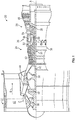
- FIG. 2 is a cross-sectional illustration of a bearing assembly 100 of a gas turbine engine 20.
- the bearing assembly 100 in some embodiments is defined radially between two rotating components of the gas turbine engine 20, for example, between the inner shaft 40 and the outer shaft 50 and components of the high pressure turbine 54 and the low pressure turbine 46.
- the high pressure turbine 54 and the low pressure turbine 46 rotate in opposite directions about the engine central longitudinal axis A, and in other embodiments the high pressure turbine 54 and the low pressure turbine 46 co-rotate, or rotate the same direction about the engine central longitudinal axis A.
- the bearing assembly 100 includes a bearing outer race 102 secured to, for example, a low pressure turbine rotor 104, and a bearing inner race 106 located radially inboard of the bearing outer race 102, and secured at the high pressure turbine 54, for example, at the outer shaft 50.
- One or more bearing elements 108 are located between the bearing outer race 102 and the bearing inner race 106.
- the bearing assembly 100 further includes a bore sleeve 110 located radially between the high pressure turbine 54 and the inner shaft 40.
- the bore sleeve 110 has a bore sleeve outer surface 112 and a bore sleeve inner surface 114 opposite the bore sleeve outer surface 112.
- the bore sleeve 110 is secured to a high pressure turbine inner surface 116 at the bore sleeve outer surface 112.
- the bore sleeve 110 may include sleeve seal elements, such as rub strips 118 which are interactive with corresponding seal elements of the inner shaft 40, such as knife edges 120. The interaction of the rub strips 118 and the knife edges 120 defines a sealing interface 122 between the bore sleeve 110 and the inner shaft 40.
- the bore sleeve 110 includes a first axial end 124 and a second axial end 126 opposite the first axial end 124.
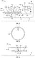
- the bore sleeve 110 is located at and secured to the high pressure turbine inner surface 116 via one or more retaining elements, such as a retaining ring 128.
- the retaining ring 128 is installed into a circumferentially-extending sleeve groove 130 defined in the bore sleeve outer surface 112 and into a corresponding circumferentially-extending turbine groove 132 formed in the high pressure turbine inner surface 116.
- the retaining ring 128 thus axially retains the bore sleeve 110 in a selected location relative to the high pressure turbine inner surface 116 and the inner shaft 40.
- the sleeve groove 130 is located axially between the first axial end 124 and the second axial end 126 of the bore sleeve 110, for example in the lowest stress or most easily accessible location of the bore sleeve 110. In some embodiments, the sleeve groove 130 is located along the middle 50% of the axial distance between the first axial end 124 and the second axial end 126. Further, in some embodiments the high pressure turbine 54 includes an axial stop 134 formed in the high pressure turbine inner surface 116, which abuts one of the first axial end 124 or the second axial end 126.
- the sleeve groove 130 is located at a sleeve opening 136 through which fluid passes for lubrication of the bearing assembly 100.
- the sleeve opening 136 aligns with an outer shaft opening 150 in the outer shaft 50, and an inner shaft opening 138 in the inner shaft 40, which also allows for fluid passage therethrough for cooling air to circumnavigate the bearing assembly 100. Aligning the sleeve groove 130 with the sleeve opening 136 and the outer shaft opening 150 allows for easy access to the retaining ring 128 for installation and/or removal of the retaining ring 128.
- a retaining ring 128 is used in some embodiments, other retaining elements may be utilized.
- a retaining clip 140 which is a split ring having clip ears 142, may be utilized.
- the clip ears 142 may be utilized to compress the retaining clip 140 to allow for disassembly of the bore sleeve 110 from the high pressure turbine 54.
- a wire 144 is utilized as the retaining element. The wire 144 may be fed circumferentially along the sleeve groove 130 via the sleeve opening 136 or the outer shaft opening 150.
- the configurations disclosed herein allow for positioning of the retaining elements at a selected location of the bore sleeve 110, for example in lower stress locations of the bore sleeve 110 or the high pressure turbine 54. Locating the retaining elements at the lower stress locations thereby allows the high pressure turbine 54 and/or bore sleeve 110 thicknesses or radial heights to be reduced. This results in lower bearing stresses and lower weight of the components.
Landscapes
- Engineering & Computer Science (AREA)
- Chemical & Material Sciences (AREA)
- Combustion & Propulsion (AREA)
- Mechanical Engineering (AREA)
- General Engineering & Computer Science (AREA)
- Turbine Rotor Nozzle Sealing (AREA)
Applications Claiming Priority (1)
| Application Number | Priority Date | Filing Date | Title |
|---|---|---|---|
| US16/918,225 US11268442B2 (en) | 2020-07-01 | 2020-07-01 | Mid mount sleeve arrangement |
Publications (2)
| Publication Number | Publication Date |
|---|---|
| EP3933170A1 true EP3933170A1 (fr) | 2022-01-05 |
| EP3933170B1 EP3933170B1 (fr) | 2024-05-22 |
Family
ID=76744734
Family Applications (1)
| Application Number | Title | Priority Date | Filing Date |
|---|---|---|---|
| EP21183201.9A Active EP3933170B1 (fr) | 2020-07-01 | 2021-07-01 | Agencement de manchon à montage ventral |
Country Status (2)
| Country | Link |
|---|---|
| US (1) | US11268442B2 (fr) |
| EP (1) | EP3933170B1 (fr) |
Families Citing this family (1)
| Publication number | Priority date | Publication date | Assignee | Title |
|---|---|---|---|---|
| FR3137407B1 (fr) * | 2022-06-30 | 2024-05-24 | Safran Aircraft Engines | Turbomachine comportant un dispositif de recuperation d’huile ameliore |
Citations (4)
| Publication number | Priority date | Publication date | Assignee | Title |
|---|---|---|---|---|
| US2866522A (en) * | 1954-08-06 | 1958-12-30 | Rolls Royce | Lubricating arrangements for bearings of rotatable shafts |
| US4693616A (en) * | 1985-09-11 | 1987-09-15 | Mtu Motoren-Und Turbinen-Union Muenchen Gmbh | Bearing for a fluid flow engine and method for damping vibrations of the engine |
| US20070177936A1 (en) * | 2006-01-30 | 2007-08-02 | Snecma | System for connecting an engine shaft with a retractable nut |
| US20120076657A1 (en) * | 2009-12-31 | 2012-03-29 | Ress Jr Robert A | Gas turbine engine and main engine rotor assembly and disassembly |
Family Cites Families (9)
| Publication number | Priority date | Publication date | Assignee | Title |
|---|---|---|---|---|
| US3602535A (en) * | 1970-05-14 | 1971-08-31 | Gen Motors Corp | Shaft coupling |
| EP0967424B1 (fr) | 1998-06-26 | 2004-03-17 | Techspace aero | Dispositif de turbomachine avec un joint d'étanchéité |
| US6579010B2 (en) * | 2001-08-31 | 2003-06-17 | General Electric Company | Retainer nut |
| FR2857708B1 (fr) * | 2003-07-15 | 2005-09-23 | Snecma Moteurs | Dispositif perfectionne de fixation d'un arbre de moteur sur un support de palier |
| FR2896827B1 (fr) * | 2006-01-27 | 2008-04-25 | Snecma Sa | Assemblage a encombrement radial reduit entre un arbre de turbine et un tourillon d'arbre de compresseur de turbomachine |
| FR2963062B1 (fr) * | 2010-07-20 | 2012-08-31 | Snecma | Assemblage entre un tourillon d'arbre de compresseur et un pignon conique pour l'entrainement d'un boitier d'accessoires d'une turbomachine |
| GB201105182D0 (en) | 2011-03-29 | 2011-05-11 | Rolls Royce Plc | An assembly comprising a rotatable component |
| FR2991386B1 (fr) * | 2012-06-05 | 2014-07-18 | Snecma | Turbomachine comportant des moyens de fixation amont d'un tube de deshuilage |
| DE102016218239A1 (de) | 2016-09-22 | 2018-03-22 | MTU Aero Engines AG | Dichtungsanordnung für ein Turbinenzwischengehäuse einer Gasturbine |
-
2020
- 2020-07-01 US US16/918,225 patent/US11268442B2/en active Active
-
2021
- 2021-07-01 EP EP21183201.9A patent/EP3933170B1/fr active Active
Patent Citations (4)
| Publication number | Priority date | Publication date | Assignee | Title |
|---|---|---|---|---|
| US2866522A (en) * | 1954-08-06 | 1958-12-30 | Rolls Royce | Lubricating arrangements for bearings of rotatable shafts |
| US4693616A (en) * | 1985-09-11 | 1987-09-15 | Mtu Motoren-Und Turbinen-Union Muenchen Gmbh | Bearing for a fluid flow engine and method for damping vibrations of the engine |
| US20070177936A1 (en) * | 2006-01-30 | 2007-08-02 | Snecma | System for connecting an engine shaft with a retractable nut |
| US20120076657A1 (en) * | 2009-12-31 | 2012-03-29 | Ress Jr Robert A | Gas turbine engine and main engine rotor assembly and disassembly |
Also Published As
| Publication number | Publication date |
|---|---|
| US11268442B2 (en) | 2022-03-08 |
| EP3933170B1 (fr) | 2024-05-22 |
| US20220003164A1 (en) | 2022-01-06 |
Similar Documents
| Publication | Publication Date | Title |
|---|---|---|
| EP4053383B1 (fr) | Porte-navette à segments de piston | |
| EP3734019A1 (fr) | Joint labyrinthe à clapet de retenue passif | |
| EP3789588B1 (fr) | Joint hydrostatique aligné avec la rotation du rotor | |
| EP3789589B1 (fr) | Joint hydrostatique | |
| EP3428390A1 (fr) | Ensemble de empilement de compresseur pour moteur de turbine à gaz | |
| EP3929408B1 (fr) | Ressort rotatif de centrage de palier amelioré pour une turbine à gaz | |
| EP3933170B1 (fr) | Agencement de manchon à montage ventral | |
| EP3517738A1 (fr) | Joint d'air externe d'une aube pour un moteur de turbine à gaz | |
| EP3816472A1 (fr) | Faisceau incurvé axialement rigide avec amortisseur d'huile | |
| EP3611338B1 (fr) | Système d'équilibrage pour une turbine à gaz avec contrepoids dans les queues d'aronde. | |
| US11286797B2 (en) | Gas turbine engine stator vane base shape | |
| US20200072072A1 (en) | Fixed vane pack retaining ring | |
| EP3760841B1 (fr) | Goupille de verrouillage anti-rotation à usages multiples | |
| EP3477061B1 (fr) | Joint d'interstice circonférentiel de segment de stator | |
| EP4560114A1 (fr) | Joint d'étanchéité pour segment de piston | |
| US12416246B2 (en) | Bearing inner race with sleeve and integrated puller | |
| EP4556684A1 (fr) | Joint coulissant de moteur à turbine à gaz | |
| US20260092568A1 (en) | Compressor bleed port with cavity intake wire | |
| EP4711586A1 (fr) | Système anti-rotation et de retenue de palier pour un moteur à turbine à gaz | |
| US11092038B2 (en) | Notched axial flange for a split case compressor | |
| EP3428404A1 (fr) | Ensemble aube de stator de moteur de turbine à gaz |
Legal Events
| Date | Code | Title | Description |
|---|---|---|---|
| PUAI | Public reference made under article 153(3) epc to a published international application that has entered the european phase |
Free format text: ORIGINAL CODE: 0009012 |
|
| STAA | Information on the status of an ep patent application or granted ep patent |
Free format text: STATUS: THE APPLICATION HAS BEEN PUBLISHED |
|
| AK | Designated contracting states |
Kind code of ref document: A1 Designated state(s): AL AT BE BG CH CY CZ DE DK EE ES FI FR GB GR HR HU IE IS IT LI LT LU LV MC MK MT NL NO PL PT RO RS SE SI SK SM TR |
|
| B565 | Issuance of search results under rule 164(2) epc |
Effective date: 20211201 |
|
| STAA | Information on the status of an ep patent application or granted ep patent |
Free format text: STATUS: REQUEST FOR EXAMINATION WAS MADE |
|
| 17P | Request for examination filed |
Effective date: 20220705 |
|
| RBV | Designated contracting states (corrected) |
Designated state(s): AL AT BE BG CH CY CZ DE DK EE ES FI FR GB GR HR HU IE IS IT LI LT LU LV MC MK MT NL NO PL PT RO RS SE SI SK SM TR |
|
| RAP3 | Party data changed (applicant data changed or rights of an application transferred) |
Owner name: RTX CORPORATION |
|
| GRAP | Despatch of communication of intention to grant a patent |
Free format text: ORIGINAL CODE: EPIDOSNIGR1 |
|
| STAA | Information on the status of an ep patent application or granted ep patent |
Free format text: STATUS: GRANT OF PATENT IS INTENDED |
|
| RIC1 | Information provided on ipc code assigned before grant |
Ipc: F01D 25/18 20060101ALI20231108BHEP Ipc: F01D 5/02 20060101AFI20231108BHEP |
|
| INTG | Intention to grant announced |
Effective date: 20231212 |
|
| GRAS | Grant fee paid |
Free format text: ORIGINAL CODE: EPIDOSNIGR3 |
|
| GRAA | (expected) grant |
Free format text: ORIGINAL CODE: 0009210 |
|
| STAA | Information on the status of an ep patent application or granted ep patent |
Free format text: STATUS: THE PATENT HAS BEEN GRANTED |
|
| AK | Designated contracting states |
Kind code of ref document: B1 Designated state(s): AL AT BE BG CH CY CZ DE DK EE ES FI FR GB GR HR HU IE IS IT LI LT LU LV MC MK MT NL NO PL PT RO RS SE SI SK SM TR |
|
| REG | Reference to a national code |
Ref country code: GB Ref legal event code: FG4D |
|
| REG | Reference to a national code |
Ref country code: CH Ref legal event code: EP |
|
| REG | Reference to a national code |
Ref country code: IE Ref legal event code: FG4D |
|
| REG | Reference to a national code |
Ref country code: DE Ref legal event code: R096 Ref document number: 602021013485 Country of ref document: DE |
|
| REG | Reference to a national code |
Ref country code: LT Ref legal event code: MG9D |
|
| REG | Reference to a national code |
Ref country code: NL Ref legal event code: MP Effective date: 20240522 |
|
| PG25 | Lapsed in a contracting state [announced via postgrant information from national office to epo] |
Ref country code: IS Free format text: LAPSE BECAUSE OF FAILURE TO SUBMIT A TRANSLATION OF THE DESCRIPTION OR TO PAY THE FEE WITHIN THE PRESCRIBED TIME-LIMIT Effective date: 20240922 |
|
| PG25 | Lapsed in a contracting state [announced via postgrant information from national office to epo] |
Ref country code: BG Free format text: LAPSE BECAUSE OF FAILURE TO SUBMIT A TRANSLATION OF THE DESCRIPTION OR TO PAY THE FEE WITHIN THE PRESCRIBED TIME-LIMIT Effective date: 20240522 |
|
| PG25 | Lapsed in a contracting state [announced via postgrant information from national office to epo] |
Ref country code: FI Free format text: LAPSE BECAUSE OF FAILURE TO SUBMIT A TRANSLATION OF THE DESCRIPTION OR TO PAY THE FEE WITHIN THE PRESCRIBED TIME-LIMIT Effective date: 20240522 Ref country code: HR Free format text: LAPSE BECAUSE OF FAILURE TO SUBMIT A TRANSLATION OF THE DESCRIPTION OR TO PAY THE FEE WITHIN THE PRESCRIBED TIME-LIMIT Effective date: 20240522 |
|
| PG25 | Lapsed in a contracting state [announced via postgrant information from national office to epo] |
Ref country code: GR Free format text: LAPSE BECAUSE OF FAILURE TO SUBMIT A TRANSLATION OF THE DESCRIPTION OR TO PAY THE FEE WITHIN THE PRESCRIBED TIME-LIMIT Effective date: 20240823 |
|
| PG25 | Lapsed in a contracting state [announced via postgrant information from national office to epo] |
Ref country code: PT Free format text: LAPSE BECAUSE OF FAILURE TO SUBMIT A TRANSLATION OF THE DESCRIPTION OR TO PAY THE FEE WITHIN THE PRESCRIBED TIME-LIMIT Effective date: 20240923 |
|
| REG | Reference to a national code |
Ref country code: AT Ref legal event code: MK05 Ref document number: 1688922 Country of ref document: AT Kind code of ref document: T Effective date: 20240522 |
|
| PG25 | Lapsed in a contracting state [announced via postgrant information from national office to epo] |
Ref country code: NL Free format text: LAPSE BECAUSE OF FAILURE TO SUBMIT A TRANSLATION OF THE DESCRIPTION OR TO PAY THE FEE WITHIN THE PRESCRIBED TIME-LIMIT Effective date: 20240522 |
|
| PG25 | Lapsed in a contracting state [announced via postgrant information from national office to epo] |
Ref country code: ES Free format text: LAPSE BECAUSE OF FAILURE TO SUBMIT A TRANSLATION OF THE DESCRIPTION OR TO PAY THE FEE WITHIN THE PRESCRIBED TIME-LIMIT Effective date: 20240522 |
|
| PG25 | Lapsed in a contracting state [announced via postgrant information from national office to epo] |
Ref country code: AT Free format text: LAPSE BECAUSE OF FAILURE TO SUBMIT A TRANSLATION OF THE DESCRIPTION OR TO PAY THE FEE WITHIN THE PRESCRIBED TIME-LIMIT Effective date: 20240522 |
|
| PG25 | Lapsed in a contracting state [announced via postgrant information from national office to epo] |
Ref country code: PL Free format text: LAPSE BECAUSE OF FAILURE TO SUBMIT A TRANSLATION OF THE DESCRIPTION OR TO PAY THE FEE WITHIN THE PRESCRIBED TIME-LIMIT Effective date: 20240522 |
|
| PG25 | Lapsed in a contracting state [announced via postgrant information from national office to epo] |
Ref country code: LV Free format text: LAPSE BECAUSE OF FAILURE TO SUBMIT A TRANSLATION OF THE DESCRIPTION OR TO PAY THE FEE WITHIN THE PRESCRIBED TIME-LIMIT Effective date: 20240522 |
|
| PG25 | Lapsed in a contracting state [announced via postgrant information from national office to epo] |
Ref country code: PT Free format text: LAPSE BECAUSE OF FAILURE TO SUBMIT A TRANSLATION OF THE DESCRIPTION OR TO PAY THE FEE WITHIN THE PRESCRIBED TIME-LIMIT Effective date: 20240923 Ref country code: PL Free format text: LAPSE BECAUSE OF FAILURE TO SUBMIT A TRANSLATION OF THE DESCRIPTION OR TO PAY THE FEE WITHIN THE PRESCRIBED TIME-LIMIT Effective date: 20240522 Ref country code: NO Free format text: LAPSE BECAUSE OF FAILURE TO SUBMIT A TRANSLATION OF THE DESCRIPTION OR TO PAY THE FEE WITHIN THE PRESCRIBED TIME-LIMIT Effective date: 20240822 Ref country code: NL Free format text: LAPSE BECAUSE OF FAILURE TO SUBMIT A TRANSLATION OF THE DESCRIPTION OR TO PAY THE FEE WITHIN THE PRESCRIBED TIME-LIMIT Effective date: 20240522 Ref country code: LV Free format text: LAPSE BECAUSE OF FAILURE TO SUBMIT A TRANSLATION OF THE DESCRIPTION OR TO PAY THE FEE WITHIN THE PRESCRIBED TIME-LIMIT Effective date: 20240522 Ref country code: IS Free format text: LAPSE BECAUSE OF FAILURE TO SUBMIT A TRANSLATION OF THE DESCRIPTION OR TO PAY THE FEE WITHIN THE PRESCRIBED TIME-LIMIT Effective date: 20240922 Ref country code: HR Free format text: LAPSE BECAUSE OF FAILURE TO SUBMIT A TRANSLATION OF THE DESCRIPTION OR TO PAY THE FEE WITHIN THE PRESCRIBED TIME-LIMIT Effective date: 20240522 Ref country code: GR Free format text: LAPSE BECAUSE OF FAILURE TO SUBMIT A TRANSLATION OF THE DESCRIPTION OR TO PAY THE FEE WITHIN THE PRESCRIBED TIME-LIMIT Effective date: 20240823 Ref country code: FI Free format text: LAPSE BECAUSE OF FAILURE TO SUBMIT A TRANSLATION OF THE DESCRIPTION OR TO PAY THE FEE WITHIN THE PRESCRIBED TIME-LIMIT Effective date: 20240522 Ref country code: ES Free format text: LAPSE BECAUSE OF FAILURE TO SUBMIT A TRANSLATION OF THE DESCRIPTION OR TO PAY THE FEE WITHIN THE PRESCRIBED TIME-LIMIT Effective date: 20240522 Ref country code: BG Free format text: LAPSE BECAUSE OF FAILURE TO SUBMIT A TRANSLATION OF THE DESCRIPTION OR TO PAY THE FEE WITHIN THE PRESCRIBED TIME-LIMIT Effective date: 20240522 Ref country code: AT Free format text: LAPSE BECAUSE OF FAILURE TO SUBMIT A TRANSLATION OF THE DESCRIPTION OR TO PAY THE FEE WITHIN THE PRESCRIBED TIME-LIMIT Effective date: 20240522 Ref country code: RS Free format text: LAPSE BECAUSE OF FAILURE TO SUBMIT A TRANSLATION OF THE DESCRIPTION OR TO PAY THE FEE WITHIN THE PRESCRIBED TIME-LIMIT Effective date: 20240822 |
|
| PG25 | Lapsed in a contracting state [announced via postgrant information from national office to epo] |
Ref country code: DK Free format text: LAPSE BECAUSE OF FAILURE TO SUBMIT A TRANSLATION OF THE DESCRIPTION OR TO PAY THE FEE WITHIN THE PRESCRIBED TIME-LIMIT Effective date: 20240522 |
|
| PG25 | Lapsed in a contracting state [announced via postgrant information from national office to epo] |
Ref country code: EE Free format text: LAPSE BECAUSE OF FAILURE TO SUBMIT A TRANSLATION OF THE DESCRIPTION OR TO PAY THE FEE WITHIN THE PRESCRIBED TIME-LIMIT Effective date: 20240522 |
|
| PG25 | Lapsed in a contracting state [announced via postgrant information from national office to epo] |
Ref country code: CZ Free format text: LAPSE BECAUSE OF FAILURE TO SUBMIT A TRANSLATION OF THE DESCRIPTION OR TO PAY THE FEE WITHIN THE PRESCRIBED TIME-LIMIT Effective date: 20240522 |
|
| PG25 | Lapsed in a contracting state [announced via postgrant information from national office to epo] |
Ref country code: SK Free format text: LAPSE BECAUSE OF FAILURE TO SUBMIT A TRANSLATION OF THE DESCRIPTION OR TO PAY THE FEE WITHIN THE PRESCRIBED TIME-LIMIT Effective date: 20240522 Ref country code: RO Free format text: LAPSE BECAUSE OF FAILURE TO SUBMIT A TRANSLATION OF THE DESCRIPTION OR TO PAY THE FEE WITHIN THE PRESCRIBED TIME-LIMIT Effective date: 20240522 |
|
| PG25 | Lapsed in a contracting state [announced via postgrant information from national office to epo] |
Ref country code: SK Free format text: LAPSE BECAUSE OF FAILURE TO SUBMIT A TRANSLATION OF THE DESCRIPTION OR TO PAY THE FEE WITHIN THE PRESCRIBED TIME-LIMIT Effective date: 20240522 Ref country code: RO Free format text: LAPSE BECAUSE OF FAILURE TO SUBMIT A TRANSLATION OF THE DESCRIPTION OR TO PAY THE FEE WITHIN THE PRESCRIBED TIME-LIMIT Effective date: 20240522 Ref country code: EE Free format text: LAPSE BECAUSE OF FAILURE TO SUBMIT A TRANSLATION OF THE DESCRIPTION OR TO PAY THE FEE WITHIN THE PRESCRIBED TIME-LIMIT Effective date: 20240522 Ref country code: DK Free format text: LAPSE BECAUSE OF FAILURE TO SUBMIT A TRANSLATION OF THE DESCRIPTION OR TO PAY THE FEE WITHIN THE PRESCRIBED TIME-LIMIT Effective date: 20240522 Ref country code: CZ Free format text: LAPSE BECAUSE OF FAILURE TO SUBMIT A TRANSLATION OF THE DESCRIPTION OR TO PAY THE FEE WITHIN THE PRESCRIBED TIME-LIMIT Effective date: 20240522 |
|
| PG25 | Lapsed in a contracting state [announced via postgrant information from national office to epo] |
Ref country code: IT Free format text: LAPSE BECAUSE OF FAILURE TO SUBMIT A TRANSLATION OF THE DESCRIPTION OR TO PAY THE FEE WITHIN THE PRESCRIBED TIME-LIMIT Effective date: 20240522 Ref country code: MC Free format text: LAPSE BECAUSE OF FAILURE TO SUBMIT A TRANSLATION OF THE DESCRIPTION OR TO PAY THE FEE WITHIN THE PRESCRIBED TIME-LIMIT Effective date: 20240522 |
|
| REG | Reference to a national code |
Ref country code: DE Ref legal event code: R097 Ref document number: 602021013485 Country of ref document: DE |
|
| REG | Reference to a national code |
Ref country code: CH Ref legal event code: PL |
|
| PG25 | Lapsed in a contracting state [announced via postgrant information from national office to epo] |
Ref country code: LU Free format text: LAPSE BECAUSE OF NON-PAYMENT OF DUE FEES Effective date: 20240701 |
|
| PLBE | No opposition filed within time limit |
Free format text: ORIGINAL CODE: 0009261 |
|
| STAA | Information on the status of an ep patent application or granted ep patent |
Free format text: STATUS: NO OPPOSITION FILED WITHIN TIME LIMIT |
|
| PG25 | Lapsed in a contracting state [announced via postgrant information from national office to epo] |
Ref country code: LU Free format text: LAPSE BECAUSE OF NON-PAYMENT OF DUE FEES Effective date: 20240701 |
|
| PG25 | Lapsed in a contracting state [announced via postgrant information from national office to epo] |
Ref country code: SI Free format text: LAPSE BECAUSE OF FAILURE TO SUBMIT A TRANSLATION OF THE DESCRIPTION OR TO PAY THE FEE WITHIN THE PRESCRIBED TIME-LIMIT Effective date: 20240522 Ref country code: BE Free format text: LAPSE BECAUSE OF NON-PAYMENT OF DUE FEES Effective date: 20240731 Ref country code: CH Free format text: LAPSE BECAUSE OF NON-PAYMENT OF DUE FEES Effective date: 20240731 |
|
| 26N | No opposition filed |
Effective date: 20250225 |
|
| REG | Reference to a national code |
Ref country code: BE Ref legal event code: MM Effective date: 20240731 |
|
| PGFP | Annual fee paid to national office [announced via postgrant information from national office to epo] |
Ref country code: GB Payment date: 20250619 Year of fee payment: 5 |
|
| PGFP | Annual fee paid to national office [announced via postgrant information from national office to epo] |
Ref country code: FR Payment date: 20250619 Year of fee payment: 5 |
|
| PG25 | Lapsed in a contracting state [announced via postgrant information from national office to epo] |
Ref country code: IE Free format text: LAPSE BECAUSE OF NON-PAYMENT OF DUE FEES Effective date: 20240701 |
|
| PG25 | Lapsed in a contracting state [announced via postgrant information from national office to epo] |
Ref country code: SE Free format text: LAPSE BECAUSE OF FAILURE TO SUBMIT A TRANSLATION OF THE DESCRIPTION OR TO PAY THE FEE WITHIN THE PRESCRIBED TIME-LIMIT Effective date: 20240522 |
|
| PGFP | Annual fee paid to national office [announced via postgrant information from national office to epo] |
Ref country code: DE Payment date: 20250620 Year of fee payment: 5 |
|
| PG25 | Lapsed in a contracting state [announced via postgrant information from national office to epo] |
Ref country code: CY Free format text: LAPSE BECAUSE OF FAILURE TO SUBMIT A TRANSLATION OF THE DESCRIPTION OR TO PAY THE FEE WITHIN THE PRESCRIBED TIME-LIMIT; INVALID AB INITIO Effective date: 20210701 |
|
| PG25 | Lapsed in a contracting state [announced via postgrant information from national office to epo] |
Ref country code: SM Free format text: LAPSE BECAUSE OF FAILURE TO SUBMIT A TRANSLATION OF THE DESCRIPTION OR TO PAY THE FEE WITHIN THE PRESCRIBED TIME-LIMIT; INVALID AB INITIO Effective date: 20210701 |
|
| PG25 | Lapsed in a contracting state [announced via postgrant information from national office to epo] |
Ref country code: HU Free format text: LAPSE BECAUSE OF FAILURE TO SUBMIT A TRANSLATION OF THE DESCRIPTION OR TO PAY THE FEE WITHIN THE PRESCRIBED TIME-LIMIT; INVALID AB INITIO Effective date: 20210701 |