EP3933183B1 - Antriebssystem eines luftfahrzeugs, das ein feuerlöschsystem mit einer löschmittelverteilungsleitung umfasst - Google Patents
Antriebssystem eines luftfahrzeugs, das ein feuerlöschsystem mit einer löschmittelverteilungsleitung umfasst Download PDFInfo
- Publication number
- EP3933183B1 EP3933183B1 EP21177681.0A EP21177681A EP3933183B1 EP 3933183 B1 EP3933183 B1 EP 3933183B1 EP 21177681 A EP21177681 A EP 21177681A EP 3933183 B1 EP3933183 B1 EP 3933183B1
- Authority
- EP
- European Patent Office
- Prior art keywords
- distribution line
- fire
- propulsion assembly
- fluid passage
- valve
- Prior art date
- Legal status (The legal status is an assumption and is not a legal conclusion. Google has not performed a legal analysis and makes no representation as to the accuracy of the status listed.)
- Active
Links
Images
Classifications
-
- B—PERFORMING OPERATIONS; TRANSPORTING
- B64—AIRCRAFT; AVIATION; COSMONAUTICS
- B64D—EQUIPMENT FOR FITTING IN OR TO AIRCRAFT; FLIGHT SUITS; PARACHUTES; ARRANGEMENT OR MOUNTING OF POWER PLANTS OR PROPULSION TRANSMISSIONS IN AIRCRAFT
- B64D27/00—Arrangement or mounting of power plants in aircraft; Aircraft characterised by the type or position of power plants
- B64D27/02—Aircraft characterised by the type or position of power plants
- B64D27/10—Aircraft characterised by the type or position of power plants of gas-turbine type
- B64D27/12—Aircraft characterised by the type or position of power plants of gas-turbine type within, or attached to, wings
-
- B—PERFORMING OPERATIONS; TRANSPORTING
- B64—AIRCRAFT; AVIATION; COSMONAUTICS
- B64D—EQUIPMENT FOR FITTING IN OR TO AIRCRAFT; FLIGHT SUITS; PARACHUTES; ARRANGEMENT OR MOUNTING OF POWER PLANTS OR PROPULSION TRANSMISSIONS IN AIRCRAFT
- B64D45/00—Aircraft indicators or protectors not otherwise provided for
-
- A—HUMAN NECESSITIES
- A62—LIFE-SAVING; FIRE-FIGHTING
- A62C—FIRE-FIGHTING
- A62C3/00—Fire prevention, containment or extinguishing specially adapted for particular objects or places
- A62C3/07—Fire prevention, containment or extinguishing specially adapted for particular objects or places in vehicles, e.g. in road vehicles
- A62C3/08—Fire prevention, containment or extinguishing specially adapted for particular objects or places in vehicles, e.g. in road vehicles in aircraft
-
- A—HUMAN NECESSITIES
- A62—LIFE-SAVING; FIRE-FIGHTING
- A62C—FIRE-FIGHTING
- A62C35/00—Permanently-installed equipment
- A62C35/58—Pipe-line systems
- A62C35/68—Details, e.g. of pipes or valve systems
-
- A—HUMAN NECESSITIES
- A62—LIFE-SAVING; FIRE-FIGHTING
- A62C—FIRE-FIGHTING
- A62C37/00—Control of fire-fighting equipment
- A62C37/36—Control of fire-fighting equipment an actuating signal being generated by a sensor separate from an outlet device
- A62C37/38—Control of fire-fighting equipment an actuating signal being generated by a sensor separate from an outlet device by both sensor and actuator, e.g. valve, being in the danger zone
- A62C37/40—Control of fire-fighting equipment an actuating signal being generated by a sensor separate from an outlet device by both sensor and actuator, e.g. valve, being in the danger zone with electric connection between sensor and actuator
-
- B—PERFORMING OPERATIONS; TRANSPORTING
- B64—AIRCRAFT; AVIATION; COSMONAUTICS
- B64D—EQUIPMENT FOR FITTING IN OR TO AIRCRAFT; FLIGHT SUITS; PARACHUTES; ARRANGEMENT OR MOUNTING OF POWER PLANTS OR PROPULSION TRANSMISSIONS IN AIRCRAFT
- B64D29/00—Power-plant nacelles, fairings or cowlings
- B64D29/02—Power-plant nacelles, fairings or cowlings associated with wings
-
- F—MECHANICAL ENGINEERING; LIGHTING; HEATING; WEAPONS; BLASTING
- F02—COMBUSTION ENGINES; HOT-GAS OR COMBUSTION-PRODUCT ENGINE PLANTS
- F02C—GAS-TURBINE PLANTS; AIR INTAKES FOR JET-PROPULSION PLANTS; CONTROLLING FUEL SUPPLY IN AIR-BREATHING JET-PROPULSION PLANTS
- F02C7/00—Features, components parts, details or accessories, not provided for in, or of interest apart form groups F02C1/00 - F02C6/00; Air intakes for jet-propulsion plants
- F02C7/24—Heat or noise insulation
- F02C7/25—Fire protection or prevention
-
- B—PERFORMING OPERATIONS; TRANSPORTING
- B64—AIRCRAFT; AVIATION; COSMONAUTICS
- B64D—EQUIPMENT FOR FITTING IN OR TO AIRCRAFT; FLIGHT SUITS; PARACHUTES; ARRANGEMENT OR MOUNTING OF POWER PLANTS OR PROPULSION TRANSMISSIONS IN AIRCRAFT
- B64D45/00—Aircraft indicators or protectors not otherwise provided for
- B64D2045/009—Fire detection or protection; Erosion protection, e.g. from airborne particles
Definitions
- the present invention relates to an aircraft propulsion system comprising a fire-fighting system with a distribution line for the distribution of a pressurized extinguishing agent.
- a propulsion assembly fixed under the wing of an aircraft comprises a turbine engine, a strut for fixing the turbine engine to the aircraft as well as a fire-fighting system for detecting and extinguishing a fire occurring on the assembly propellant.
- the fire-fighting system contains two tanks of extinguishing agent with controlled opening which are arranged in the mast, a distribution line, in the form of pipes, connecting the tanks to the fire zones of the turbomachine, and a detection and control assembly. activation to detect a fire and command the opening of the tanks in order to trigger the emission of extinguishing agent from the tanks to the fire zones through the distribution line.
- the space available in the mast for the passage of the distribution line of the fire-fighting system is limited and constrained by the presence of a plurality of systems. On some aircraft, it is not possible to route the extinguishing agent distribution line without locally generating at least one low point.
- the distribution line is a standby line, it is filled with ambient air which enters from the fire zones. This air contains humidity which condenses and accumulates at low points, and freezes when the aircraft flies at high altitude, thus preventing the proper functioning of the fire suppression system.
- a drainage device in the form of a hole, is therefore arranged at each low point to evacuate, by gravity, the water which could accumulate there.
- Such a drainage hole is effective in evacuating stagnant water, but in the event of opening of a tank, part of the extinguishing agent is lost through this hole. This makes it necessary to increase the volume of extinguishing agent in the tank to compensate for this loss and leads to tanks that are bulkier and therefore more difficult to integrate into the mast.
- the invention aims to meet all or part of this need and relates to a propulsion assembly comprising a turbine engine attached to a mast, and a fire-fighting system, as claimed in claim 1.
- the patent application FR3015568 describes the preamble of claim 1.
- the invention thus makes it possible to avoid increasing the volume of extinguishing agent in the tanks (aimed at compensating for the loss of agent through the drainage hole in the prior art) and therefore to limit the volume/mass of the tanks embarked.
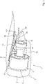
- FIG. 1 is a schematic representation of a propulsion assembly of an aircraft which comprises a pressurized extinguishing agent distribution line according to the invention
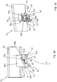
- the figure 2a is a sectional view of a drainage device of the distribution line of the figure 1 , according to a first embodiment of the invention
- FIG 2b is a perspective view of the drainage device shown in figure 2a ;
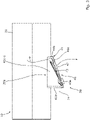
- the picture 3 is a view similar to the figure 2a , of a section of a drainage device of the distribution line of the figure 1 , according to a second embodiment of the invention
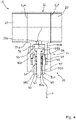
- the figure 4 is a view similar to the figure 2a , of a section of a drainage device of the distribution line of the figure 1 , according to a third embodiment of the invention.
- a propulsion unit 1 is attached under the wing W of an aircraft (not shown) and comprises a turbomachine 2 comprising a nacelle 3 surrounding an engine 4, a mast 5 fixed to the wing W and under which the turbomachine is attached 2, as well as a fire protection system 6.
- the turbomachine 2 comprises a plurality of fire zones Z1, Z2, separated from one another by walls and fire seals (not shown) to contain a fire within the limits of a fire zone and prevent its spread to another fire zone.
- the fire-fighting system 6 is provided to detect and extinguish, by sending an extinguishing agent, any fire which may occur in one of the fire zones Z1, Z2.
- the fire-fighting system 6 contains two reservoirs R1, R2 with controlled opening and each containing a volume of extinguishing agent under pressure, a distribution line 10 of extinguishing agent connecting each of the reservoirs R1, R2 to nozzles ejection (not shown) of extinguishing agent located in the fire zones Z1, Z2, and a detection and activation unit 11 for detecting a fire and controlling the opening of the tanks R1, R2.
- Each tank R1, R2 is located in the mast 5 and is equipped with an opening system to release the extinguishing agent out of the tank R1, R2.
- the opening system (not shown) is for example of the butterfly valve type, or of the pyrotechnic type.
- the detection and activation unit 11 comprises a central unit to which are connected a plurality of fire sensors located in the fire zones Z1, Z2 to detect a fire in the latter, and the central unit is, moreover, connected to the tank opening systems to control their opening.
- the detection and activation unit 11 is connected to controls and devices of the aircraft. Upon detection of a fire, the detection and activation unit 11 sends a fire alarm signal to the pilots.
- the cockpit comprises two activation controls, each being associated with a single tank R1, R2 and operable by the pilot to send an activation signal of the tank associated with the detection unit.
- the detection and activation unit 11 Upon activation of a command associated with a tank R1, R2, the detection and activation unit 11 sends an opening signal to the tank opening system for the opening of said tank R1, R2.
- the extinguishing agent released moves under pressure in the distribution line and is expelled into the fire zones Z1, Z2 through the ejection nozzles.
- the distribution line 10 comprises a piping consisting of pipes 20 connected to each other to ensure the circulation of the extinguishing agent.
- the detection line 10 includes one or more low points 21 (only one shown).
- a low point 21 is a point of the distribution line 10 where fluids tend to accumulate due to the lower height of this point compared to the points of the distribution line 10 directly located upstream and downstream of the point bottom 21.
- the terms upstream and downstream being chosen according to the direction of flow of the extinguishing agent in the distribution line, that is to say from the reservoirs R1, R2 towards the nozzles.
- the distribution line 10 comprises a drainage device 30 arranged at the level of each low point 21 with a fluid passage P making it possible to evacuate the fluids from the distribution line 10.
- the drainage device 30 comprises a frame 31 fixed to a pipe 20 as well as a blocking mechanism 32 of the fluid passage P, fixed to the frame 31, which comprises a movable device of the movable valve type 33 and an elastic means 34 mechanically coupled to valve 33.
- the frame 31 has the overall shape of an open box with four side walls 31a-d parallel in pairs and a flat wall 31e fixed to the four side walls and which forms the bottom of the frame 31.
- the side walls 31a-d are all fixed to the distribution line 10, for example by tight welding, at the level of an opening 20a made in a pipe 20 in line with the low point 21.
- the side walls 31a-d extend outside the pipe, towards the bottom of the latter, so as not to impede the circulation of the extinguishing agent.
- the bottom of the frame 31e is thus at a distance from the pipe 20.
- each of the side walls is provided with a through hole 35.
- the through holes 35 of the two side walls are identical and aligned.
- the bottom 31e comprises, for its part, an opening 37 to allow the evacuation of liquids at the level of the low point 21.
- a fluid can flow through the fluid passage P going from the pipe 20 to the drainage device 30 and which comprises the opening 20a made in the pipe 20 in line with the low point 21 then the opening 37 of the bottom 31e of the frame.
- the valve 33 of the shutter mechanism 32 comprises a panel 33a to which are fixed two hinge fittings 33b, distributed on either side of the width of the panel 33a, each being provided with an orifice (not shown) for the passage of pin 36. Hinge fittings 33b are fitted onto pin 36 so that valve 33 is pivotally mounted on the frame between a rest position in which it releases opening 37 of bottom 31e and opens the fluid passage P, and a closed position in which it closes the opening 37 and closes the fluid passage P thus preventing the flow of a fluid out of the distribution line 10.
- the elastic means 34 is a torsion spring fitted on the pin 36 and arranged between the two hinge fittings 33b of the valve.
- a first end 34a of the spring is fixed to the panel 33a of the valve while a second end 34b of the spring is fixed to the frame 31, for example fixed to the bottom 31e of the frame as illustrated in the figures 2a-b .
- the spring 34 is constrained so that the rest position of the spring 34 corresponds to the rest position of the valve 33, in which the latter releases the opening 37 of the bottom 31e.
- the torsion spring 34 forces the valve 33 into a position of rest in which it releases the bottom opening 31e and therefore opens the fluid passage P.
- the drainage device 30 thus makes it possible to drain the water which could accumulate at the level of the low point 21 of the distribution line 10 and to avoid the formation of an ice cube which could block the distribution line 10. from the percussion of a reservoir R1, R2 and as long as the distribution line 10 is pressurized, the drainage device 30 according to the invention makes it possible to limit the loss of extinguishing agent.
- the invention thus makes it possible to avoid increasing the volume of agent in the reservoirs R1, R2 (aimed at compensating for the loss of agent through the drainage hole in the prior art) and therefore to limit the volume/mass on-board tanks.
- the drainage device 30 comprises a frame 41 fixed to a pipe 20 as well as a closure mechanism 42 of the fluid passage P, where the closure mechanism 42 comprises a leaf spring 43 fixed to the frame 41.
- the chassis 41 generally has the shape of an open box with four side walls 41a-d parallel in pairs and a flat wall 41e fixed to the four side walls 41a-d and which forms the bottom of the chassis 41.
- the side walls 41a-d are all fixed to the pipe 20, for example by tight welding, at the level of an opening 20a made in the pipe 20 at the right of the low point 21.
- the side walls 41a-d extend completely outside the pipe 20, towards the bottom of the latter, so as not to impede the passage of the extinguishing agent.
- the bottom 41e of the frame is thus at a distance from the pipe 20.
- a fluid can flow through the fluid passage P going from the pipe 20 to the drainage device 30 which comprises the opening 20a made in the pipe 20 at the right of the low point 21 then the through hole 47 of the bottom 41e of the chassis .
- the leaf spring 43 is arranged inside the frame 41, that is to say between the side walls 41a-d, and fixed to the bottom 41e of the frame.
- the fixing of the leaf spring 43 is carried out via conventional fixing means, such as for example rivets 43a.
- the leaf spring 43 extends partly above the drainage hole 47.
- the leaf spring 43 is a thin flexible band and is prestressed in a rest position in which it is curved upwards with respect to the bottom 41e and releases the through hole 47 to open the fluid passage P.
- the leaf spring 43 is movable between its rest position and a closed position in which it is pressed against the bottom 41e and closes the through orifice 47 to close the fluid passage P thereby preventing the flow of a fluid out of distribution line 10.
- the leaf spring 43 In operation, when the distribution line is filled with ambient air (normal configuration where there is no impact from one of the reservoirs), the leaf spring 43 is in its rest position.
- the drainage device 30 comprises a frame 51 having the form of a connection with a tapping duct 51b and the closure mechanism 52 of the fluid passage P comprises a valve with rod 53, movably mounted in the tapping duct 51b, as well as an elastic means 54 mechanically coupled to said valve.
- the frame 51 for example of the T-type, comprises a main body 51a to which the tapping duct 51b is fixed by projecting out of the main body 51a, an intermediate part 51c arranged partly in the tapping duct 51b and ensuring the guiding of the valve 53, as well as a nut 51d to secure the intermediate piece 51c to the tapping duct 51b.
- the main body 51a is hollow, of cylindrical shape, and is connected to a pipe 20 of the distribution line 10 by conventional means, for example of the screwing or welding type, at each of its ends 51e-f.
- the tapping duct 51b of cylindrical shape, comprises a blind bore 55 and a through hole 55a made at the bottom of the blind bore.
- the bore 55a opens into the main body 51a by crossing the outer wall of said body.
- the tapping duct 51b extends in length downwards so that a fluid arriving in the main body 51a is evacuated out of the body, under the effect of gravity, through the bore 55a. Note that in the example of figure 4 , the tapping duct 51b extends lengthwise in a radial direction of the main body 51a.
- the intermediate piece 51c has a cylindrical shape and includes a collar 56, placed approximately halfway along the intermediate piece 51c.
- the intermediate piece 51c is machined and comprises, at its first end 56a, a first bore 57 of a diameter substantially greater than the diameter of the valve stem 53a, and on its second end 56b, a countersink 58 followed a second bore 59 concentric with the first bore 57 and the countersink 58 and having a diameter greater than the diameter of the first bore 57.
- the first bore 57 leads to the second bore 58 and the countersink leads to the second bore 58.
- the bottom of the second bore 58 is pierced with a multitude of orifices 60, called drain discharge orifices, opening onto the first end 56a of the intermediate piece 51c, the countersink 58 has a shape complementary to that of the head 53b of valve to form a valve seat.
- the periphery of the tapping duct 51b is threaded.
- the intermediate piece 51c is inserted, partly in the tapping duct, in the blind bore 55, and is held in place in the latter by the nut 51d screwed onto the periphery of the tapping duct.
- the intermediate piece 51c is inserted, via its second end 56b, into the bore 55 of the tapping duct 51b and a first shoulder of the collar 56 comes into abutment against the edge of the tapping duct 51b.
- the nut 51d comprises a shoulder which bears against a second shoulder of the collar 55 to hold the intermediate piece 51c against the edge of the tapping duct 51b.
- the contact between the intermediate part 51c and the tapping duct 51b alone ensures the seal between these two parts.
- a fluid can flow through the fluid passage P going from a pipe 20 to the drainage device 30 and which comprises the bore 55a made at the bottom of the blind bore 55 of the tapping conduit 51b, the valve seat 58 , and drain discharge ports 60.
- the valve 53 has its stem 53a received, in part, in the first bore 57 of the intermediate piece 51c in order to ensure its guiding in translation.
- the valve head 53b is arranged between the valve seat 58 and the bottom of the blind bore 55 of the tapping duct.
- the valve 53 is mounted in sliding connection on the intermediate part of the frame between a rest position in which its head 53b is at a distance from the valve seat 58, and a closed position in which its head 53b closes the valve seat 58 and closes the fluid passage P thus preventing the flow of a fluid out of the distribution line 10.
- the elastic means 54 is a helical-shaped compression spring, called a lifting spring, fitted onto the stem 53a of the valve 53 and received in the second bore 59 of the intermediate piece. One end of the spring rests on the bottom of the second bore 59 of the intermediate piece.
- the lifting spring 54 is constrained so that the rest position of the spring corresponds to the rest position of the valve 53.
- the head 53b of the valve from the rest position of said valve, is closer to the valve seat 58, the stress of the spring returns the valve 53 to its rest position.
- the lifting spring 54 forces the valve into a rest position in which it opens the valve seat 58 and therefore the fluid passage P.
Landscapes
- Engineering & Computer Science (AREA)
- Chemical & Material Sciences (AREA)
- Combustion & Propulsion (AREA)
- Health & Medical Sciences (AREA)
- Public Health (AREA)
- Business, Economics & Management (AREA)
- Emergency Management (AREA)
- Aviation & Aerospace Engineering (AREA)
- Mechanical Engineering (AREA)
- General Engineering & Computer Science (AREA)
- Fire-Extinguishing By Fire Departments, And Fire-Extinguishing Equipment And Control Thereof (AREA)
Claims (7)
- Antriebsanordnung (1), die ein Turbotriebwerk (2), das an einem Pylon (5) angebracht ist, und ein Feuerlöschsystem (6) umfasst, wobei das Turbotriebwerk (2) mehrere Feuerzonen (Z1, Z2) umfasst, wobei das Feuerlöschsystem (6) zwei Reservoirs (R1, R2) von unter Druck stehendem Löschmittel, die sich in dem Pylon (5) befinden, und eine Verteilerleitung, die jedes der Reservoirs (R1, R2) mit in den Feuerzonen (Z1, Z2) befindlichen Düsen umfasst, wobei die Verteilerleitung (10) eine Anordnung aus Rohren (20) umfasst, die miteinander verbunden sind und mindestens einen Tiefpunkt (21) zwischen den Reservoirs (R1, R2) und den Düsen und für jeden Tiefpunkt eine Fluidablassvorrichtung (30) zum Abführen des Fluids aus der Verteilerleitung (10) aufweisen, dadurch gekennzeichnet, dass die Ablassvorrichtung (30) einen Fluidkanal (P) zum Abführen von Fluid nach außerhalb der Verteilerleitung (10) und einen Mechanismus (32, 42, 52) zum Sperren des Fluidkanals (P) umfasst, wobei der Mechanismus (32, 42, 52) unter der Wirkung des in der Verteilerleitung (10) herrschenden Drucks zwischen einer ersten Bereitschaftsstellung, in der er den Fluidkanal (P) öffnet, und einer zweiten Stellung, in der er den Fluidkanal (P) schließt, beweglich ist, wobei die zweite Stellung erreicht wird, wenn der Druck in der Verteilerleitung (10) größer gleich einem vorbestimmten Druck ist.
- Antriebsanordnung (1) nach Anspruch 1,
dadurch gekennzeichnet, dass der Sperrmechanismus (32, 42, 52) eine Vorrichtung (33, 53) umfasst, die zwischen einer Ruhestellung, in der sie den Fluidkanal (P) öffnet, und einer Sperrstellung, in der sie den Fluidkanal (P) schließt, beweglich ist. - Antriebsanordnung (1) nach Anspruch 2, dadurch gekennzeichnet, dass die Ablassvorrichtung (30) ein Chassis (31, 41, 51) umfasst, das an mindestens einem Rohr (20) fixiert ist und an dem der Sperrmechanismus (32, 42, 52) fixiert ist.
- Antriebsanordnung (1) nach Anspruch 3, dadurch gekennzeichnet, dass der Sperrmechanismus (42) ein Federblatt (43) ist.
- Antriebsanordnung (1) nach Anspruch 3, dadurch gekennzeichnet, dass der Sperrmechanismus (32, 52) ein elastisches Mittel (34, 54) umfasst, das dahingehend mit der beweglichen Vorrichtung (33, 53) mechanisch gekoppelt ist, die Vorrichtung in ihre Ruhestellung zurückzuführen.
- Antriebsanordnung (1) nach Anspruch 5, dadurch gekennzeichnet, dass die bewegliche Vorrichtung eine Klappe (33), die in Schwenkverbindung an dem Chassis (31) befestigt ist, ist und das elastische Mittel (34) eine Torsionsfeder ist, die sowohl an der Klappe (33) als auch an dem Chassis (31) fixiert ist.
- Antriebsanordnung (1) nach Anspruch 5, dadurch gekennzeichnet, dass die bewegliche Vorrichtung ein Ventil (53), das translatorisch beweglich in dem Chassis (51) befestigt ist, ist und das elastische Mittel eine Feder (54) ist, die auf das Ventil aufgebracht ist.
Applications Claiming Priority (1)
| Application Number | Priority Date | Filing Date | Title |
|---|---|---|---|
| FR2007005A FR3112121A1 (fr) | 2020-07-02 | 2020-07-02 | Ensemble propulsif d’un aeronef comprenant un systeme anti-incendie avec une ligne de distribution d’agent extincteur. |
Publications (2)
| Publication Number | Publication Date |
|---|---|
| EP3933183A1 EP3933183A1 (de) | 2022-01-05 |
| EP3933183B1 true EP3933183B1 (de) | 2022-08-10 |
Family
ID=72709581
Family Applications (1)
| Application Number | Title | Priority Date | Filing Date |
|---|---|---|---|
| EP21177681.0A Active EP3933183B1 (de) | 2020-07-02 | 2021-06-04 | Antriebssystem eines luftfahrzeugs, das ein feuerlöschsystem mit einer löschmittelverteilungsleitung umfasst |
Country Status (4)
| Country | Link |
|---|---|
| US (1) | US11524192B2 (de) |
| EP (1) | EP3933183B1 (de) |
| CN (1) | CN113879545A (de) |
| FR (1) | FR3112121A1 (de) |
Families Citing this family (1)
| Publication number | Priority date | Publication date | Assignee | Title |
|---|---|---|---|---|
| FR3137371A1 (fr) | 2022-07-01 | 2024-01-05 | Airbus Operations (S.A.S.) | Ensemble propulsif d’un aeronef comprenant un systeme anti-incendie avec une ligne de distribution d’agent extincteur. |
Family Cites Families (3)
| Publication number | Priority date | Publication date | Assignee | Title |
|---|---|---|---|---|
| FR3014133B1 (fr) * | 2013-12-04 | 2015-12-25 | Snecma | Mat d'evacuation de fluides draines pour un ensemble propulsif |
| FR3015568B1 (fr) | 2013-12-24 | 2016-01-01 | Snecma | Ventilation d'un ensemble propulsif d'aeronef |
| DE102018222162A1 (de) * | 2018-12-18 | 2020-06-18 | Rolls-Royce Deutschland Ltd & Co Kg | Belüftungs- und Löschvorrichtung für ein Gasturbinentriebwerk |
-
2020
- 2020-07-02 FR FR2007005A patent/FR3112121A1/fr not_active Ceased
-
2021
- 2021-06-04 EP EP21177681.0A patent/EP3933183B1/de active Active
- 2021-06-29 CN CN202110730316.6A patent/CN113879545A/zh active Pending
- 2021-06-29 US US17/362,568 patent/US11524192B2/en active Active
Also Published As
| Publication number | Publication date |
|---|---|
| FR3112121A1 (fr) | 2022-01-07 |
| US20220001223A1 (en) | 2022-01-06 |
| EP3933183A1 (de) | 2022-01-05 |
| US11524192B2 (en) | 2022-12-13 |
| CN113879545A (zh) | 2022-01-04 |
Similar Documents
| Publication | Publication Date | Title |
|---|---|---|
| EP2205325B1 (de) | Fluidausstossvorrichtung mit verbesserter dichtheit | |
| EP2414242B1 (de) | Betankungsvorrichtung für trägerraketenantrieb | |
| EP2178751B1 (de) | Triebwerksgondel mit mindestens einer überdruckklappe | |
| EP0037334B1 (de) | Absperrventilvorrichtung mit Überdrucksicherung | |
| EP0010465A2 (de) | Sich automatisch öffnendes Ventil, insbesondere für Feuerlöschanlagen | |
| EP3933183A1 (de) | Antriebssystem eines luftfahrzeugs, das ein feuerlöschsystem mit einer löschmittelverteilungsleitung umfasst | |
| FR3094892A1 (fr) | Systeme anti-incendie pour un aeronef comportant un reservoir a double chambre | |
| FR2550607A1 (fr) | Regulateur destine a etre monte sur le raccord de sortie d'une bouteille de gaz ou recipient analogue | |
| EP0579519B1 (de) | Servogesteuertes Ventil | |
| EP2958642A2 (de) | Sprinkler mit in position gehaltenem absperrteil mittels eines schmelzelements mithilfe einer beweglichen lagervorrichtung | |
| EP3681606B1 (de) | Kombiniertes brandschutzsystem zur früherkennung von rauch und gas und brandschutz | |
| EP3909652B1 (de) | Luftfahrzeug, das eine antriebseinheit und ein brandschutzsystem für diese antriebseinheit umfasst | |
| EP3253607B1 (de) | Kraftstofftank mit überdruckschutz | |
| EP4455021A1 (de) | Flugzeug mit mindestens einer wasserstoffversorgungsvorrichtung mit mindestens einem gasabführungssystem im falle eines lecks | |
| EP2623162B1 (de) | Sprühkopf | |
| FR3139120A3 (fr) | Ensemble propulsif d’un aeronef comprenant un systeme anti-incendie avec une ligne de distribution d’agent extincteur. | |
| FR3137371A1 (fr) | Ensemble propulsif d’un aeronef comprenant un systeme anti-incendie avec une ligne de distribution d’agent extincteur. | |
| EP4458682B1 (de) | Flugzeug mit mindestens einer flüssigkeitsversorgungsschaltung mit mindestens einem selbstschliessenden verschluss | |
| FR2681399A1 (fr) | Dispositif d'arret automatique et de securite destine notamment aux postes de detente de gaz. | |
| EP4495008B1 (de) | Flugzeuggondel mit einem abgedichteten gehäuse und einer tür, die das gehäuse nach aussen öffnet | |
| EP2958639B1 (de) | Brandbekämpfungsanlage mit einem netz von vakuumsprinklern, ausgelöst durch einen aktuator mit einem kolben und gesteuert durch einen master-aktuator | |
| EP3868649B1 (de) | Luftfahrzeug, das mit einem boden und einer brandschutz- und/oder rauchschutz-klappe ausgestattet ist | |
| FR2930817A1 (fr) | Systeme d'obturation d'un conduit d'evacuation des gaz d'un lanceur de missiles | |
| FR2922972A1 (fr) | Dispositif d'ejection de fluide et utilisation d'un tel dispositif. | |
| WO2020053494A1 (fr) | Installation de lutte contre les incendies avec clapet, ainsi que l'utilisation d'un clapet dans une installation de lutte contre les incendies |
Legal Events
| Date | Code | Title | Description |
|---|---|---|---|
| PUAI | Public reference made under article 153(3) epc to a published international application that has entered the european phase |
Free format text: ORIGINAL CODE: 0009012 |
|
| STAA | Information on the status of an ep patent application or granted ep patent |
Free format text: STATUS: REQUEST FOR EXAMINATION WAS MADE |
|
| 17P | Request for examination filed |
Effective date: 20210604 |
|
| AK | Designated contracting states |
Kind code of ref document: A1 Designated state(s): AL AT BE BG CH CY CZ DE DK EE ES FI FR GB GR HR HU IE IS IT LI LT LU LV MC MK MT NL NO PL PT RO RS SE SI SK SM TR |
|
| B565 | Issuance of search results under rule 164(2) epc |
Effective date: 20211108 |
|
| RIC1 | Information provided on ipc code assigned before grant |
Ipc: B64D 45/00 20060101ALN20220404BHEP Ipc: F02C 7/25 20060101AFI20220404BHEP |
|
| GRAP | Despatch of communication of intention to grant a patent |
Free format text: ORIGINAL CODE: EPIDOSNIGR1 |
|
| STAA | Information on the status of an ep patent application or granted ep patent |
Free format text: STATUS: GRANT OF PATENT IS INTENDED |
|
| RIC1 | Information provided on ipc code assigned before grant |
Ipc: B64D 45/00 20060101ALN20220506BHEP Ipc: F02C 7/25 20060101AFI20220506BHEP |
|
| GRAS | Grant fee paid |
Free format text: ORIGINAL CODE: EPIDOSNIGR3 |
|
| INTG | Intention to grant announced |
Effective date: 20220520 |
|
| GRAA | (expected) grant |
Free format text: ORIGINAL CODE: 0009210 |
|
| STAA | Information on the status of an ep patent application or granted ep patent |
Free format text: STATUS: THE PATENT HAS BEEN GRANTED |
|
| AK | Designated contracting states |
Kind code of ref document: B1 Designated state(s): AL AT BE BG CH CY CZ DE DK EE ES FI FR GB GR HR HU IE IS IT LI LT LU LV MC MK MT NL NO PL PT RO RS SE SI SK SM TR |
|
| RBV | Designated contracting states (corrected) |
Designated state(s): AL AT BE BG CH CY CZ DE DK EE ES FI FR GB GR HR HU IE IS IT LI LT LU LV MC MK MT NL NO PL PT RO RS SE SI SK SM TR |
|
| REG | Reference to a national code |
Ref country code: AT Ref legal event code: REF Ref document number: 1510709 Country of ref document: AT Kind code of ref document: T Effective date: 20220815 Ref country code: CH Ref legal event code: EP |
|
| REG | Reference to a national code |
Ref country code: IE Ref legal event code: FG4D Free format text: LANGUAGE OF EP DOCUMENT: FRENCH |
|
| REG | Reference to a national code |
Ref country code: DE Ref legal event code: R096 Ref document number: 602021000299 Country of ref document: DE |
|
| REG | Reference to a national code |
Ref country code: NL Ref legal event code: MP Effective date: 20220810 |
|
| REG | Reference to a national code |
Ref country code: LT Ref legal event code: MG9D |
|
| PG25 | Lapsed in a contracting state [announced via postgrant information from national office to epo] |
Ref country code: SE Free format text: LAPSE BECAUSE OF FAILURE TO SUBMIT A TRANSLATION OF THE DESCRIPTION OR TO PAY THE FEE WITHIN THE PRESCRIBED TIME-LIMIT Effective date: 20220810 Ref country code: RS Free format text: LAPSE BECAUSE OF FAILURE TO SUBMIT A TRANSLATION OF THE DESCRIPTION OR TO PAY THE FEE WITHIN THE PRESCRIBED TIME-LIMIT Effective date: 20220810 Ref country code: PT Free format text: LAPSE BECAUSE OF FAILURE TO SUBMIT A TRANSLATION OF THE DESCRIPTION OR TO PAY THE FEE WITHIN THE PRESCRIBED TIME-LIMIT Effective date: 20221212 Ref country code: NO Free format text: LAPSE BECAUSE OF FAILURE TO SUBMIT A TRANSLATION OF THE DESCRIPTION OR TO PAY THE FEE WITHIN THE PRESCRIBED TIME-LIMIT Effective date: 20221110 Ref country code: NL Free format text: LAPSE BECAUSE OF FAILURE TO SUBMIT A TRANSLATION OF THE DESCRIPTION OR TO PAY THE FEE WITHIN THE PRESCRIBED TIME-LIMIT Effective date: 20220810 Ref country code: LV Free format text: LAPSE BECAUSE OF FAILURE TO SUBMIT A TRANSLATION OF THE DESCRIPTION OR TO PAY THE FEE WITHIN THE PRESCRIBED TIME-LIMIT Effective date: 20220810 Ref country code: LT Free format text: LAPSE BECAUSE OF FAILURE TO SUBMIT A TRANSLATION OF THE DESCRIPTION OR TO PAY THE FEE WITHIN THE PRESCRIBED TIME-LIMIT Effective date: 20220810 Ref country code: FI Free format text: LAPSE BECAUSE OF FAILURE TO SUBMIT A TRANSLATION OF THE DESCRIPTION OR TO PAY THE FEE WITHIN THE PRESCRIBED TIME-LIMIT Effective date: 20220810 |
|
| REG | Reference to a national code |
Ref country code: AT Ref legal event code: MK05 Ref document number: 1510709 Country of ref document: AT Kind code of ref document: T Effective date: 20220810 |
|
| PG25 | Lapsed in a contracting state [announced via postgrant information from national office to epo] |
Ref country code: PL Free format text: LAPSE BECAUSE OF FAILURE TO SUBMIT A TRANSLATION OF THE DESCRIPTION OR TO PAY THE FEE WITHIN THE PRESCRIBED TIME-LIMIT Effective date: 20220810 Ref country code: IS Free format text: LAPSE BECAUSE OF FAILURE TO SUBMIT A TRANSLATION OF THE DESCRIPTION OR TO PAY THE FEE WITHIN THE PRESCRIBED TIME-LIMIT Effective date: 20221210 Ref country code: HR Free format text: LAPSE BECAUSE OF FAILURE TO SUBMIT A TRANSLATION OF THE DESCRIPTION OR TO PAY THE FEE WITHIN THE PRESCRIBED TIME-LIMIT Effective date: 20220810 Ref country code: GR Free format text: LAPSE BECAUSE OF FAILURE TO SUBMIT A TRANSLATION OF THE DESCRIPTION OR TO PAY THE FEE WITHIN THE PRESCRIBED TIME-LIMIT Effective date: 20221111 |
|
| PG25 | Lapsed in a contracting state [announced via postgrant information from national office to epo] |
Ref country code: SM Free format text: LAPSE BECAUSE OF FAILURE TO SUBMIT A TRANSLATION OF THE DESCRIPTION OR TO PAY THE FEE WITHIN THE PRESCRIBED TIME-LIMIT Effective date: 20220810 Ref country code: RO Free format text: LAPSE BECAUSE OF FAILURE TO SUBMIT A TRANSLATION OF THE DESCRIPTION OR TO PAY THE FEE WITHIN THE PRESCRIBED TIME-LIMIT Effective date: 20220810 Ref country code: ES Free format text: LAPSE BECAUSE OF FAILURE TO SUBMIT A TRANSLATION OF THE DESCRIPTION OR TO PAY THE FEE WITHIN THE PRESCRIBED TIME-LIMIT Effective date: 20220810 Ref country code: DK Free format text: LAPSE BECAUSE OF FAILURE TO SUBMIT A TRANSLATION OF THE DESCRIPTION OR TO PAY THE FEE WITHIN THE PRESCRIBED TIME-LIMIT Effective date: 20220810 Ref country code: CZ Free format text: LAPSE BECAUSE OF FAILURE TO SUBMIT A TRANSLATION OF THE DESCRIPTION OR TO PAY THE FEE WITHIN THE PRESCRIBED TIME-LIMIT Effective date: 20220810 Ref country code: AT Free format text: LAPSE BECAUSE OF FAILURE TO SUBMIT A TRANSLATION OF THE DESCRIPTION OR TO PAY THE FEE WITHIN THE PRESCRIBED TIME-LIMIT Effective date: 20220810 |
|
| REG | Reference to a national code |
Ref country code: DE Ref legal event code: R097 Ref document number: 602021000299 Country of ref document: DE |
|
| PG25 | Lapsed in a contracting state [announced via postgrant information from national office to epo] |
Ref country code: SK Free format text: LAPSE BECAUSE OF FAILURE TO SUBMIT A TRANSLATION OF THE DESCRIPTION OR TO PAY THE FEE WITHIN THE PRESCRIBED TIME-LIMIT Effective date: 20220810 Ref country code: EE Free format text: LAPSE BECAUSE OF FAILURE TO SUBMIT A TRANSLATION OF THE DESCRIPTION OR TO PAY THE FEE WITHIN THE PRESCRIBED TIME-LIMIT Effective date: 20220810 |
|
| PLBE | No opposition filed within time limit |
Free format text: ORIGINAL CODE: 0009261 |
|
| STAA | Information on the status of an ep patent application or granted ep patent |
Free format text: STATUS: NO OPPOSITION FILED WITHIN TIME LIMIT |
|
| PG25 | Lapsed in a contracting state [announced via postgrant information from national office to epo] |
Ref country code: AL Free format text: LAPSE BECAUSE OF FAILURE TO SUBMIT A TRANSLATION OF THE DESCRIPTION OR TO PAY THE FEE WITHIN THE PRESCRIBED TIME-LIMIT Effective date: 20220810 |
|
| 26N | No opposition filed |
Effective date: 20230511 |
|
| PG25 | Lapsed in a contracting state [announced via postgrant information from national office to epo] |
Ref country code: MC Free format text: LAPSE BECAUSE OF FAILURE TO SUBMIT A TRANSLATION OF THE DESCRIPTION OR TO PAY THE FEE WITHIN THE PRESCRIBED TIME-LIMIT Effective date: 20220810 |
|
| PG25 | Lapsed in a contracting state [announced via postgrant information from national office to epo] |
Ref country code: MC Free format text: LAPSE BECAUSE OF FAILURE TO SUBMIT A TRANSLATION OF THE DESCRIPTION OR TO PAY THE FEE WITHIN THE PRESCRIBED TIME-LIMIT Effective date: 20220810 |
|
| REG | Reference to a national code |
Ref country code: BE Ref legal event code: MM Effective date: 20230630 |
|
| PG25 | Lapsed in a contracting state [announced via postgrant information from national office to epo] |
Ref country code: LU Free format text: LAPSE BECAUSE OF NON-PAYMENT OF DUE FEES Effective date: 20230604 |
|
| REG | Reference to a national code |
Ref country code: IE Ref legal event code: MM4A |
|
| PG25 | Lapsed in a contracting state [announced via postgrant information from national office to epo] |
Ref country code: LU Free format text: LAPSE BECAUSE OF NON-PAYMENT OF DUE FEES Effective date: 20230604 |
|
| PG25 | Lapsed in a contracting state [announced via postgrant information from national office to epo] |
Ref country code: IE Free format text: LAPSE BECAUSE OF NON-PAYMENT OF DUE FEES Effective date: 20230604 |
|
| PG25 | Lapsed in a contracting state [announced via postgrant information from national office to epo] |
Ref country code: IE Free format text: LAPSE BECAUSE OF NON-PAYMENT OF DUE FEES Effective date: 20230604 |
|
| PG25 | Lapsed in a contracting state [announced via postgrant information from national office to epo] |
Ref country code: IT Free format text: LAPSE BECAUSE OF FAILURE TO SUBMIT A TRANSLATION OF THE DESCRIPTION OR TO PAY THE FEE WITHIN THE PRESCRIBED TIME-LIMIT Effective date: 20220810 Ref country code: BE Free format text: LAPSE BECAUSE OF NON-PAYMENT OF DUE FEES Effective date: 20230630 |
|
| PG25 | Lapsed in a contracting state [announced via postgrant information from national office to epo] |
Ref country code: BG Free format text: LAPSE BECAUSE OF FAILURE TO SUBMIT A TRANSLATION OF THE DESCRIPTION OR TO PAY THE FEE WITHIN THE PRESCRIBED TIME-LIMIT Effective date: 20220810 |
|
| PG25 | Lapsed in a contracting state [announced via postgrant information from national office to epo] |
Ref country code: BG Free format text: LAPSE BECAUSE OF FAILURE TO SUBMIT A TRANSLATION OF THE DESCRIPTION OR TO PAY THE FEE WITHIN THE PRESCRIBED TIME-LIMIT Effective date: 20220810 |
|
| REG | Reference to a national code |
Ref country code: CH Ref legal event code: PL |
|
| PG25 | Lapsed in a contracting state [announced via postgrant information from national office to epo] |
Ref country code: CH Free format text: LAPSE BECAUSE OF NON-PAYMENT OF DUE FEES Effective date: 20240630 |
|
| PGFP | Annual fee paid to national office [announced via postgrant information from national office to epo] |
Ref country code: DE Payment date: 20250618 Year of fee payment: 5 |
|
| PGFP | Annual fee paid to national office [announced via postgrant information from national office to epo] |
Ref country code: GB Payment date: 20250618 Year of fee payment: 5 |
|
| PGFP | Annual fee paid to national office [announced via postgrant information from national office to epo] |
Ref country code: FR Payment date: 20250627 Year of fee payment: 5 |
|
| PG25 | Lapsed in a contracting state [announced via postgrant information from national office to epo] |
Ref country code: CY Free format text: LAPSE BECAUSE OF FAILURE TO SUBMIT A TRANSLATION OF THE DESCRIPTION OR TO PAY THE FEE WITHIN THE PRESCRIBED TIME-LIMIT; INVALID AB INITIO Effective date: 20210604 |
|
| PG25 | Lapsed in a contracting state [announced via postgrant information from national office to epo] |
Ref country code: HU Free format text: LAPSE BECAUSE OF FAILURE TO SUBMIT A TRANSLATION OF THE DESCRIPTION OR TO PAY THE FEE WITHIN THE PRESCRIBED TIME-LIMIT; INVALID AB INITIO Effective date: 20210604 |
|
| PG25 | Lapsed in a contracting state [announced via postgrant information from national office to epo] |
Ref country code: TR Free format text: LAPSE BECAUSE OF FAILURE TO SUBMIT A TRANSLATION OF THE DESCRIPTION OR TO PAY THE FEE WITHIN THE PRESCRIBED TIME-LIMIT Effective date: 20220810 |
|
| PG25 | Lapsed in a contracting state [announced via postgrant information from national office to epo] |
Ref country code: SI Free format text: LAPSE BECAUSE OF FAILURE TO SUBMIT A TRANSLATION OF THE DESCRIPTION OR TO PAY THE FEE WITHIN THE PRESCRIBED TIME-LIMIT Effective date: 20220810 |