EP3933232A1 - Kolbenring mit hartbeschichtung - Google Patents
Kolbenring mit hartbeschichtung Download PDFInfo
- Publication number
- EP3933232A1 EP3933232A1 EP21177973.1A EP21177973A EP3933232A1 EP 3933232 A1 EP3933232 A1 EP 3933232A1 EP 21177973 A EP21177973 A EP 21177973A EP 3933232 A1 EP3933232 A1 EP 3933232A1
- Authority
- EP
- European Patent Office
- Prior art keywords
- ring
- piston ring
- hardness
- piston
- outer circumferential
- Prior art date
- Legal status (The legal status is an assumption and is not a legal conclusion. Google has not performed a legal analysis and makes no representation as to the accuracy of the status listed.)
- Granted
Links
Images



Classifications
-
- F—MECHANICAL ENGINEERING; LIGHTING; HEATING; WEAPONS; BLASTING
- F16—ENGINEERING ELEMENTS AND UNITS; GENERAL MEASURES FOR PRODUCING AND MAINTAINING EFFECTIVE FUNCTIONING OF MACHINES OR INSTALLATIONS; THERMAL INSULATION IN GENERAL
- F16J—PISTONS; CYLINDERS; SEALINGS
- F16J9/00—Piston-rings, e.g. non-metallic piston-rings, seats therefor; Ring sealings of similar construction
- F16J9/12—Details
- F16J9/14—Joint-closures
- F16J9/16—Joint-closures obtained by stacking of rings
-
- F—MECHANICAL ENGINEERING; LIGHTING; HEATING; WEAPONS; BLASTING
- F16—ENGINEERING ELEMENTS AND UNITS; GENERAL MEASURES FOR PRODUCING AND MAINTAINING EFFECTIVE FUNCTIONING OF MACHINES OR INSTALLATIONS; THERMAL INSULATION IN GENERAL
- F16J—PISTONS; CYLINDERS; SEALINGS
- F16J9/00—Piston-rings, e.g. non-metallic piston-rings, seats therefor; Ring sealings of similar construction
- F16J9/12—Details
- F16J9/14—Joint-closures
-
- F—MECHANICAL ENGINEERING; LIGHTING; HEATING; WEAPONS; BLASTING
- F02—COMBUSTION ENGINES; HOT-GAS OR COMBUSTION-PRODUCT ENGINE PLANTS
- F02B—INTERNAL-COMBUSTION PISTON ENGINES; COMBUSTION ENGINES IN GENERAL
- F02B25/00—Engines characterised by using fresh charge for scavenging cylinders
- F02B25/02—Engines characterised by using fresh charge for scavenging cylinders using unidirectional scavenging
- F02B25/04—Engines having ports both in cylinder head and in cylinder wall near bottom of piston stroke
-
- F—MECHANICAL ENGINEERING; LIGHTING; HEATING; WEAPONS; BLASTING
- F16—ENGINEERING ELEMENTS AND UNITS; GENERAL MEASURES FOR PRODUCING AND MAINTAINING EFFECTIVE FUNCTIONING OF MACHINES OR INSTALLATIONS; THERMAL INSULATION IN GENERAL
- F16J—PISTONS; CYLINDERS; SEALINGS
- F16J9/00—Piston-rings, e.g. non-metallic piston-rings, seats therefor; Ring sealings of similar construction
-
- F—MECHANICAL ENGINEERING; LIGHTING; HEATING; WEAPONS; BLASTING
- F16—ENGINEERING ELEMENTS AND UNITS; GENERAL MEASURES FOR PRODUCING AND MAINTAINING EFFECTIVE FUNCTIONING OF MACHINES OR INSTALLATIONS; THERMAL INSULATION IN GENERAL
- F16J—PISTONS; CYLINDERS; SEALINGS
- F16J9/00—Piston-rings, e.g. non-metallic piston-rings, seats therefor; Ring sealings of similar construction
- F16J9/26—Piston-rings, e.g. non-metallic piston-rings, seats therefor; Ring sealings of similar construction characterised by the use of particular materials
-
- F—MECHANICAL ENGINEERING; LIGHTING; HEATING; WEAPONS; BLASTING
- F02—COMBUSTION ENGINES; HOT-GAS OR COMBUSTION-PRODUCT ENGINE PLANTS
- F02B—INTERNAL-COMBUSTION PISTON ENGINES; COMBUSTION ENGINES IN GENERAL
- F02B75/00—Other engines
- F02B75/02—Engines characterised by their cycles, e.g. six-stroke
- F02B2075/022—Engines characterised by their cycles, e.g. six-stroke having less than six strokes per cycle
- F02B2075/025—Engines characterised by their cycles, e.g. six-stroke having less than six strokes per cycle two
Definitions
- the disclosure relates to, a piston ring for use in a ring pack in a ring groove in a piston of a large two-stroke turbo-charged uniflow-scavenged internal combustion engine with crossheads, in particular a piston ring that is provided with a hard coating on the outer circumferential face.
- the engine pistons are provided with a ring pack that seals against the combustion pressure in order to prevent combustion gases penetrating the scavenge space.
- the piston rings ensure cylinder oil is evenly distributed to form the lubricating film on the inner side of the cylinder liner.
- the piston rings in the ring pack seal a piston oscillating at a speed of approximately 10 m/sec for compressed air and combustion gasses at a pressure of around 250 bar pressure and a temperature of around 400 °C and using only a few drops of cylinder oil per engine revolution as lubrication, and all with an expected service life of many thousand hours. Therefore, the main requirements for piston rings are high resistance to wear and corrosion and a low drop in elasticity at high temperatures.
- the inner walls of the cylinder liners are lubricated with a special cylinder lubrication oil that protects the inner walls of the cylinder liners from the aggressive components of the combustion gases.
- a special cylinder lubrication oil that protects the inner walls of the cylinder liners from the aggressive components of the combustion gases.
- piston rings for four-stroke internal combustion engines have a sharp edge/transition between the outer circumferential surface and the side face that faces the crankshaft, to ensure the scraping effect.
- the transition between the outer circumferential face and the side face that faces the crankshaft of a piston ring for a large two-stroke turbo-charged uniflow-scavenged internal combustion engine needs to be a rounded edge/transition to avoid scraping the cylinder oil from the inner surface of the cylinder liner during the stroke of the piston towards bottom dead center.
- the transition between the outer circumferential face in the side face that faces the combustion chamber needs to be rounded for the same reasons of distributing the cylinder oil over the cylinder liner, to thereby protect the cylinder liner.
- the rounded transition has a funneling effect on the cylinder oil, i.e. the opposite of the scraping effect.
- the ring pack of a large two-stroke turbo-charged uniflow-scavenged internal combustion engine with crossheads typically includes three or four piston rings.
- the top piston ring can be a Controlled Pressure Relief ring (CPR ring), i.e. the piston ring concerned or the groove in the piston concerned is provided with pressure relief grooves that allow for a well-defined and control flow of hot gas from the combustion chamber to the underside of the top piston ring thereby reducing the pressure drop over the top ring and distributing the load over several rings in the ring pack.
- the lowest piston ring is not a CPR ring i.e. is gas-tight.
- all of the piston rings are gas-tight, including the top ring, thereby rendering the lower piston rings more or less passive.
- the peripheral outer side of the piston rings is coated with a hard coating that prolongs the lifetime of the piston rings and intended for reducing scuffing of the cylinder liner.
- a hard coating that prolongs the lifetime of the piston rings and intended for reducing scuffing of the cylinder liner.
- a piston ring for use in a piston ring pack in an annular ring groove in the sidewall of a piston of a large two-stroke turbocharged uniflow-scavenged internal combustion engine with crossheads to seal against the pressure in the combustion chamber, the piston ring comprising:
- the inventors have realized that varying degrees ring twist, caused by the varying pressure during the load cycle and by different levels of engine load (mean effective pressure) is a major factor in the risk of scuffing.
- the inventors arrived at the insight that a hard coating over the full height of the ring (the full outer circumferential face) has the drawback that the desired barrel shape of the outer circumferential face is neither maintained nor achieved through wear of the outer circumferential face.
- the transitions between the outer circumferential face and the side faces become sharp due to wear and will cause the piston ring to scrape the cylinder oil film from the inner surface of the cylinder liner when the twist is high, e.g. due to high engine load and accordingly high pressures in the combustion chamber.
- Such scraping with the consequent removal of the cylinder oil film from the inner surface of the cylinder liner is likely to increase the risk of scuffing.
- the inventors also arrived at the insight that it would be advantageous to ensure that the surface area of the peripheral outer face close to the transition to the side faces is less hard than a medial area of the peripheral outer face so that this less hard material will be removed by (abrasive) wear faster than the portion of the medial surface area of the peripheral outer face and the resulting receded transitions form together with the inner surface of the cylinder liner a wedge-shaped recess that acts as a funnel for the cylinder oil film on the inner side of the cylinder liner.
- the medial surface area in between the soft areas is hard coated to ensure durability of the piston ring, and assists in forming the above-mentioned wedge-shaped recess by the hard-coated area not wearing as easily as the less hard surface area of the outer circumferential face close to the transition to the side faces.
- the term "medial” in this context is “medial” as seen in the axial direction of the piston ring.
- the material that forms the surface close to the transition to the side faces is in a possible implementation form of the first aspect of the same material as the material of the main ring body.
- the material that forms the surface close to the transition to the side faces is different from the material of the main ring body.
- the first hardness is a Vickers hardness between 350 to 550 HV.
- the second hardness is a Brinell hardness of 200 to 300 HB.
- the outer circumferential face bulges radially.
- the outer circumferential face bulges radially with a first radius that is 0,5 to 1,5 times the diameter of the piston ring.
- the medial portion extends over a hard height, and wherein the hard height is between 50 and 75% of the ring height.
- the medial portion is formed by a hard coating.
- the hard coating is applied to the ring body by spraying.
- the largest radial thickness of the hard coating is between 1,5% and 4% of the ring height.
- the hardness of the first- and second peripheral portions relative to the hardness of the medial portion is selected such that the surface of the first and second peripheral portions become, due to wear during use, receded relative to the surface of the medial portion.
- the first- and second peripheral portions become receded during use relative to an imaginary curved extension of the radially bulging surface of the medial portion, the first-and second peripheral portions preferably being receded relative to the imaginary curved extension by a distance equaling 0,045% to 2% of the ring height.
- a surface of the receded first- and second peripheral portions forms together with an inner wall of a cylinder liner an oil wedge guiding cylinder oil to the medial portion.
- the first- and/or second side face is at least partially chromium plated.
- the piston ring has an outer diameter in the range between 300 mm and 1000 mm.
- the ring height is between 1,4 and 2,5 percent of the ring outer diameter.
- the first hardness is at least 1,4 times greater than the second hardness, when measured by a Vickers/Brinell hardness test.
- the medial portion together with the first- and second peripheral portions form the complete outer circumferential face.
- the first hardness is substantially greater than the second hardness, preferably as measured by a Vickers hardness test.
- the ring body is made of vermicular cast iron.
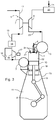
- Figs. 1 and 2 are elevated views of a large low-speed turbocharged two-stroke internal combustion engine with a crankshaft 8 and crossheads 9.
- the engine can be operated with the Diesel (compression ignited) or the Otto cycle (timed ignition).
- Fig. 3 shows a diagrammatic representation of the large low-speed turbocharged two-stroke internal combustion engine of Figs. 1 and 2 with its intake and exhaust systems.
- the engine has six cylinders in line.
- Large low-speed turbocharged two-stroke diesel engines have typically between four and fourteen cylinders in line, carried by a cylinder frame 23 that is carried by an engine frame 11.
- the engine may e.g. be used as the main engine in a marine vessel or as a stationary engine for operating a generator in a power station.
- the total output of the engine may, for example, range from 1,000 to 110,000 kW.
- the engine is in this example embodiment a compression-ignited engine of the two-stroke uniflow type with scavenge air ports 18 at the lower region of the cylinder liners 1 and a central exhaust valve 4 at the top of the cylinder liners 1.
- the scavenge air is passed from the scavenge air receiver 2 to the scavenge air ports 18 of the individual cylinders 1.
- a piston 10 in the cylinder liner 1 compresses the scavenge air, fuel is injected into the combustion chamber 32 through fuel injection valves 24 in the cylinder cover 22, combustion follows, and exhaust gas is generated.
- the exhaust gas flows through an exhaust duct associated with the cylinder 1 into the exhaust gas receiver 3 and onwards through a first exhaust conduit 19 to a turbine 6 of the turbocharger 5, from which the exhaust gas flows away through a second exhaust conduit via an economizer 20 to an outlet 21 and into the atmosphere.
- the turbine 6 drives a compressor 7 supplied with fresh air via an air inlet 12.
- the compressor 7 delivers pressurized scavenge air to a scavenge air conduit 13 leading to the scavenge air receiver 2.
- the scavenge air in conduit 13 passes an intercooler 14 for cooling the scavenge air.
- the cooled scavenge air passes via an auxiliary blower 16 driven by an electric motor 17 that pressurizes the scavenge airflow when the compressor 7 of the turbocharger 5 does not deliver sufficient pressure for the scavenge air receiver 2, i.e. in low- or partial load conditions of the engine.
- the turbocharger compressor 7 delivers sufficient compressed scavenge air and then the auxiliary blower 16 is bypassed via a non-return valve 15.
- the engine is operated with a given fuel, such as, marine diesel, heavy fuel oil, (liquified) natural gas, coal gas, biogas, Methanol, Ethanol, Ethane, landfill gas, methane, ethylene or (liquified) petroleum gas (non-exhaustive list), that is supplied by a fuel supply system.
- a given fuel such as, marine diesel, heavy fuel oil, (liquified) natural gas, coal gas, biogas, Methanol, Ethanol, Ethane, landfill gas, methane, ethylene or (liquified) petroleum gas (non-exhaustive list), that is supplied by a fuel supply system.
- Figs. 4 and 5 show a piston 10, the cylindrical sidewall of which is provided with several ring grooves 33, of which the top groove 33 receives a piston top ring 34 and the lower piston rings 36 have been inserted in the lower grooves 33.
- the top piston ring 34 and the lower piston rings 36 of a single piston 10 form together a so-called ring pack of cooperating piston rings 34,36.
- the piston 10 is of the large two-stroke turbo-charged uniflow-scavenged engine with crossheads and the piston 10 defines together with the cylinder liner 1 and the cylinder cover 22 a combustion chamber 32 (it is noted that Fig. 5 does not show an exhaust valve in the cylinder cover 22 but it is understood that an exhaust valve will be present in the cylinder cover 22).
- the piston rings 34,36 prevent the gas pressure in the combustion chamber 32 from penetrating to the space below the piston 1.
- Figs. 6 and 7 illustrate an example embodiment of a top piston ring 34 with a ring partition which substantially prevents gas flow through the partition.
- the piston top ring 34 has a ring body 50 with a partition, which renders it possible partly to expand the ring diameter at the mounting in the ring groove 33, partly to permit two engaging end portions 38,39 of the top piston ring 34 to withdraw from each other as the top piston ring 34 gets worn during use.
- the ring body 50 has first- and second side faces 46,47 axially distanced by a ring height Hr, an outer circumferential face 41 extending axially over the ring height Hr, and an inner circumferential face 42 extending axially over the ring height Hr.
- the first side surface 46 is intended to be facing the combustion chamber 32 and the second side surface 47 is intended to face away from the combustion chamber 32.
- the outer circumferential face 41 of the top piston ring 34 has in an embodiment pressure relief grooves 45, which extend obliquely at an angle in relation to the plane of the top piston ring 34.
- the pressure relief grooves 45 ensure a controlled gas flow from the top side to the lower side of the piston top ring 34, and thus a uniform and suitably delimited gas flow through the individual groove 45.
- the outer rim of the ring groove 33 is indicated by an interrupted line 40.
- An outer circumferential face 41 of the top piston ring 34 is in contact with the inner surface of the cylinder liner 1.
- the top piston ring 34 is not provided with pressure relief grooves and the pressure relief function is e.g. provided by grooves in the piston (not shown). It is also possible to operate the top piston ring 34 without controlled leakage, i.e. a gas-tight top piston ring 34 that handles substantially the complete pressure difference over the piston 10.
- Figs. 10 and 11 illustrate an example embodiment of a lower piston ring 36, with a ring partition formed by engaging end portions 38, 39.
- the lower piston ring 36 is essentially identical to the top piston ring 34, except for the presence of the pressure relief grooves in the top piston ring 34, and sometimes a different choice of material for the ring body 50, as set out in greater detail further below.
- Fig. 12 shows a sectional detail of the (top or lower) piston ring 34, 36 of an unused (factory new) piston ring 34, 36.
- Fig. 13 illustrates a similar section of the piston ring 34, 36, with the convexity of the outer circumferential surface 41 substantially exaggerated for illustrative purposes.
- the outer circumferential surface 41 preferably has a symmetric convex running surface profile (when not yet used).
- the radius R1 of the curve describing the convexity of the peripheral surface 41 of an unused piston ring 34, 36 is 0,5 to 1,5 times the outer diameter of the piston ring.
- the outer circumferential face 41 bulges radially, with a first radius R1.
- the arrow illustrating the radius R1 in Fig. 12 is shown with a "zigzag" to indicate that the actual length of the arrow is larger than shown in Fig. 12 , for the practical reason of fitting the arrow in the available area for the figure.
- the medial portion of outer circumferential surface 41 is in an embodiment provided with a hard coating 52.
- the surface of the hard coating 52 is from factory convex with the radius R1.
- the thickness of the hard coating is indicated by the arrow CT.
- the extent of the height of the hard coating is indicated by arrow Hc.
- the transition between the first side surface 46 and the outer circumferential surface 41 and between the second side surface 47 and the outer circumferential surface 41 are both rounded with a diameter R2, and R2 preferably corresponds to approximately 0,01 to 0,1 times the ring height Hr.
- the medial portion of the axial extent of the outer circumferential face 41 has a first hardness (measured, for example with a Vickers hardness test).
- a first peripheral portion of the axial extent of the outer circumferential face 41 that extends from the medial portion to the first transition has a second hardness (measured, for example with a Vickers hardness test).
- the first peripheral portion extends over a height H1.
- a second peripheral portion of the extent of the outer circumferential face 41 that extends from the medial portion to the second transition has a second hardness (measured, for example with a Vickers hardness test).
- the second peripheral portion extends over a height H2.
- the first and second height H1, H2 are not necessarily identical in length.
- the surface of the first and second peripheral portion preferably have the same hardness, but this is not necessarily the case, as long as the hardness of the first and second peripheral are both lower than the hardness of the surface of the medial portion
- the medial portion of the outer circumferential face 41 is formed by a hard coating 52, e.g. a thermal spray coating, galvanic coating, or other suitable hard coding.
- the medial portion of the outer circumferential face is provided with the required hardness by surface treatment.
- the first hardness is greater than the second hardness so that the medial portion wears out slower than the peripheral portions.
- the outer circumferential face 41 assumes the shape as shown in Fig. 14 after wear ( Fig. 14 will be described in greater detail further below).
- the first hardness is a Vickers hardness between 350 to 550 HV.
- the second hardness is a Brinell hardness of 200 to 300HB
- the medial portion extends over a hard height Hc.
- the hard height Hc is between 50 and 75% of the ring height Hr.
- the largest radial thickness CT of the hard coating 52 is between 1,5% and 4% of the ring height Hr.
- the first peripheral portion extends axially over a height H1 and is formed by material of the ring body 50
- the second peripheral portion extends axially over a height H2 and is formed by material of the ring body 50.
- the hardness of the first- and second peripheral portions relative to the hardness of the medial portion is selected such that the surface of the first and second peripheral portions become, due to wear during use, receded relative to the surface of the medial portion.
- the surface of the receded first- and second peripheral portions forms together with an inner wall of a cylinder liner an oil wedge guiding cylinder oil towards the medial portion.
- first- and/or second side faces 46, 47 are at least partially chromium plated.
- the piston ring 34, 36 has an outer diameter in the range between 300 mm and 1000 mm.
- the ring height Hr is between 1,4 and 2,5 percent of the ring outer diameter.
- the first hardness is at least 1,4 times greater than the second hardness, when measured by a Vickers/Brinell hardness test.
- the outer circumferential surface 41 has an asymmetric convex running surface profile.
- Fig. 14 shows a piston ring 34, 36 after being used for a period of time.
- the first- and second peripheral portions have become receded during use relative to an imaginary curved extension (shown by the interrupted line in Fig. 14 ) of the radially bulging s urface of the medial portion, the first- and second peripheral portions preferably being receded relative to the imaginary curved extension by a distance OR (oil Recess) equaling in an embodiment 0,045% to 2% of the ring height Hr.
- the medial portion has an edge covering a height OW (Oil Wedge), this edge being disposed at an angle to the remainder of the medial portion forming the relatively sharp transition from the medial portion to the first- and second peripheral portions.
- OW Height Wedge
- the receded first-and second portions together with the edge of the medial portion form an ideal profile for guiding cylinder oil towards the main section of the medial portion, thereby ensuring that there is no scraping of the cylinder oil, also with varying ring twist.
- the surface of the first and second peripheral portion being softer than the surface of the medial portion results in the piston ring 34, 36 achieving an ideal shape to reduce the risk of scraping and thereby reduce the risk of scuffing of the cylinder liner 1.
- the material hardness of the surface of the ring body 50 at the peripheral portions is 10>HVB/HVA > 1.4
- the material hardness of the surface of the medial portion is 500>HVB>5000.
- the dimensions after wear in relation to Hr are: 2 % > OW > 7 % 0.045 % > OR > 2 % 1.5 % > CT > 4 % 50 % > Hc > 80 %
- all piston rings 34,36 in a ring pack are manufactured to be slightly non-circular. This non-circular form is required so that the piston ring exerts an exactly defined pressure over the whole ring circumference when inserted in the circular cylinder liner 1. This pressure can in principle be distributed evenly over the circumference; however, a negative oval form is generally aimed for in a top piston 34 for use in a piston 10 of a large two-stroke turbocharged uniflow-scavenged internal combustion engine. This means that the pressure in the area of the partition is lower than on the remaining circumference which avoids increased pressure on the partition during operation of the engine.
- the main body of the top piston ring 34 is a temper-hardened casting with inclusions of vermicular graphite for use in the first groove, while in the lower grooves, the main body of the piston rings is of an alloyed grey cast iron, for example, vermicular cast-iron.
- the main body of all of the piston rings of a ring pack is of vermicular cast-iron.
- a ring pack comprises:
- a ring pack comprises:
Landscapes
- Engineering & Computer Science (AREA)
- General Engineering & Computer Science (AREA)
- Mechanical Engineering (AREA)
- Chemical & Material Sciences (AREA)
- Combustion & Propulsion (AREA)
- Pistons, Piston Rings, And Cylinders (AREA)
Applications Claiming Priority (1)
| Application Number | Priority Date | Filing Date | Title |
|---|---|---|---|
| DKPA202070391A DK180594B1 (en) | 2020-06-15 | 2020-06-15 | A piston ring for use in a ring pack in a piston of a large two-stroke turbo-charged uniflow-scavenged internal combustion engine with crossheads |
Publications (3)
| Publication Number | Publication Date |
|---|---|
| EP3933232A1 true EP3933232A1 (de) | 2022-01-05 |
| EP3933232B1 EP3933232B1 (de) | 2023-10-25 |
| EP3933232C0 EP3933232C0 (de) | 2023-10-25 |
Family
ID=76305784
Family Applications (1)
| Application Number | Title | Priority Date | Filing Date |
|---|---|---|---|
| EP21177973.1A Active EP3933232B1 (de) | 2020-06-15 | 2021-06-07 | Kolbenring mit hartbeschichtung |
Country Status (5)
| Country | Link |
|---|---|
| EP (1) | EP3933232B1 (de) |
| JP (1) | JP7163452B2 (de) |
| KR (3) | KR20210155774A (de) |
| CN (1) | CN113803187A (de) |
| DK (1) | DK180594B1 (de) |
Cited By (1)
| Publication number | Priority date | Publication date | Assignee | Title |
|---|---|---|---|---|
| CN116696586A (zh) * | 2022-03-02 | 2023-09-05 | 曼能解决方案(曼能解决方案德国股份公司)分公司 | 用于大型二冲程涡轮增压单流扫气十字头内燃机的活塞环 |
Citations (8)
| Publication number | Priority date | Publication date | Assignee | Title |
|---|---|---|---|---|
| GB1399997A (en) * | 1972-02-14 | 1975-07-02 | Nippon Piston Ring Co Ltd | Piston rings |
| US4256318A (en) * | 1980-04-28 | 1981-03-17 | Sealed Power Corporation | Piston ring |
| JPS5746048A (en) * | 1980-09-03 | 1982-03-16 | Riken Corp | Piston ring and its manufacturing method of internal combustion engine |
| JP2002332561A (ja) * | 2001-05-09 | 2002-11-22 | Riken Corp | ピストンリングの部分窒化方法および部分窒化ピストンリング |
| JP2005273583A (ja) * | 2004-03-25 | 2005-10-06 | Toyota Motor Corp | ピストンリング |
| US20060040125A1 (en) * | 2002-10-15 | 2006-02-23 | Kabushiki Kaisha Riken | Piston ring and thermal spray coating used therein, and method for manufacturing thereof |
| DE102010047836A1 (de) * | 2010-10-07 | 2012-04-12 | Federal-Mogul Burscheid Gmbh | Verfahren zur Herstellung eines Kolbenrings |
| DE112011103828T5 (de) * | 2010-11-18 | 2013-08-22 | Isuzu Motors Limited | Kolbenring |
Family Cites Families (20)
| Publication number | Priority date | Publication date | Assignee | Title |
|---|---|---|---|---|
| JPS5823256A (ja) * | 1981-08-05 | 1983-02-10 | Toyota Motor Corp | ピストンリング |
| DE3305920A1 (de) * | 1982-03-12 | 1983-09-22 | Dana Corp., 43615 Toledo, Ohio | Kolbenring |
| JPS59150949A (ja) * | 1983-02-18 | 1984-08-29 | Toyota Motor Corp | ピストンリング |
| JPS60187741A (ja) * | 1984-03-05 | 1985-09-25 | Toyota Motor Corp | ピストンリングとその製造方法 |
| JPS6232266A (ja) * | 1985-08-02 | 1987-02-12 | Riken Corp | 内燃機関用ピストンリングの製造方法 |
| JPH0434268A (ja) * | 1990-05-30 | 1992-02-05 | Teikoku Piston Ring Co Ltd | 溶射ピストンリング |
| JP2681863B2 (ja) * | 1993-04-07 | 1997-11-26 | 株式会社リケン | ディーゼルエンジン用のシリンダライナとピストンリングの組合せ |
| US20090174150A1 (en) * | 2008-01-08 | 2009-07-09 | Thomas Smith | Lateral side protection of a piston ring with a thermally sprayed coating |
| AU2009238281B1 (en) | 2009-11-16 | 2010-10-28 | CITS Engineering Pty Limited | Improvements in two-stroke engines |
| US20120205876A1 (en) * | 2009-11-30 | 2012-08-16 | Nippon Piston Ring Co., Ltd. | Piston ring |
| BRPI0905228B1 (pt) * | 2009-12-29 | 2017-01-24 | Mahle Metal Leve Sa | anel de pistão nitretado resistente à propagação de trincas |
| DE102011120145A1 (de) * | 2010-12-24 | 2012-06-28 | Mahle International Gmbh | Kolbenring für einen Kolben eines Verbrennungsmotors und Verfahren zu seiner Herstellung |
| DE102011010656A1 (de) * | 2011-02-09 | 2012-08-09 | Federal-Mogul Burscheid Gmbh | Kolbenring |
| DE102011076453B4 (de) * | 2011-05-25 | 2013-08-01 | Federal-Mogul Burscheid Gmbh | Kolbenring mit Verbundbeschichtung |
| WO2013137060A1 (ja) * | 2012-03-14 | 2013-09-19 | 株式会社リケン | シリンダとピストンリングとの組合せ |
| JP6496578B2 (ja) * | 2015-03-12 | 2019-04-03 | 株式会社リケン | ピストンリング |
| JP2017036823A (ja) * | 2015-08-07 | 2017-02-16 | 日本ピストンリング株式会社 | ピストンリング |
| DK179019B1 (en) * | 2015-11-12 | 2017-08-28 | Man Diesel & Turbo Filial Af Man Diesel & Turbo Se Tyskland | A top piston ring for a large two-stroke turbocharged compression ignited internal combustion engine with crossheads |
| CN106402381B (zh) * | 2016-10-12 | 2018-08-07 | 桃源县三力活塞环厂(普通合伙) | 一种新型活塞环 |
| JP2024046048A (ja) * | 2022-09-22 | 2024-04-03 | 三菱電機株式会社 | プレー分析装置、プレー分析システム、プレー分析方法およびプログラム |
-
2020
- 2020-06-15 DK DKPA202070391A patent/DK180594B1/en active IP Right Grant
-
2021
- 2021-06-07 EP EP21177973.1A patent/EP3933232B1/de active Active
- 2021-06-10 JP JP2021096980A patent/JP7163452B2/ja active Active
- 2021-06-11 CN CN202110653694.9A patent/CN113803187A/zh active Pending
- 2021-06-15 KR KR1020210077291A patent/KR20210155774A/ko not_active Ceased
-
2023
- 2023-05-09 KR KR1020230060171A patent/KR20230071105A/ko not_active Ceased
-
2024
- 2024-07-04 KR KR1020240088284A patent/KR102882667B1/ko active Active
Patent Citations (8)
| Publication number | Priority date | Publication date | Assignee | Title |
|---|---|---|---|---|
| GB1399997A (en) * | 1972-02-14 | 1975-07-02 | Nippon Piston Ring Co Ltd | Piston rings |
| US4256318A (en) * | 1980-04-28 | 1981-03-17 | Sealed Power Corporation | Piston ring |
| JPS5746048A (en) * | 1980-09-03 | 1982-03-16 | Riken Corp | Piston ring and its manufacturing method of internal combustion engine |
| JP2002332561A (ja) * | 2001-05-09 | 2002-11-22 | Riken Corp | ピストンリングの部分窒化方法および部分窒化ピストンリング |
| US20060040125A1 (en) * | 2002-10-15 | 2006-02-23 | Kabushiki Kaisha Riken | Piston ring and thermal spray coating used therein, and method for manufacturing thereof |
| JP2005273583A (ja) * | 2004-03-25 | 2005-10-06 | Toyota Motor Corp | ピストンリング |
| DE102010047836A1 (de) * | 2010-10-07 | 2012-04-12 | Federal-Mogul Burscheid Gmbh | Verfahren zur Herstellung eines Kolbenrings |
| DE112011103828T5 (de) * | 2010-11-18 | 2013-08-22 | Isuzu Motors Limited | Kolbenring |
Cited By (4)
| Publication number | Priority date | Publication date | Assignee | Title |
|---|---|---|---|---|
| CN116696586A (zh) * | 2022-03-02 | 2023-09-05 | 曼能解决方案(曼能解决方案德国股份公司)分公司 | 用于大型二冲程涡轮增压单流扫气十字头内燃机的活塞环 |
| EP4239227A1 (de) | 2022-03-02 | 2023-09-06 | MAN Energy Solutions, filial af MAN Energy Solutions SE, Tyskland | Kolbenring für einen grossen turboaufgeladenen gleichstromgespülten kreuzkopfverbrennungsmotor mit zwei schritten |
| CN116696586B (zh) * | 2022-03-02 | 2024-06-07 | 曼能解决方案(曼能解决方案德国股份公司)分公司 | 用于大型二冲程涡轮增压单流扫气十字头内燃机的活塞环 |
| EP4239227B1 (de) * | 2022-03-02 | 2025-12-03 | Everllence, filial af Everllence SE, Tyskland | Kolbenring für einen grossen turboaufgeladenen gleichstromgespülten kreuzkopfverbrennungsmotor mit zwei schritten |
Also Published As
| Publication number | Publication date |
|---|---|
| JP7163452B2 (ja) | 2022-10-31 |
| KR20230071105A (ko) | 2023-05-23 |
| KR102882667B1 (ko) | 2025-11-07 |
| DK202070391A1 (en) | 2021-09-30 |
| KR20210155774A (ko) | 2021-12-23 |
| DK180594B1 (en) | 2021-09-30 |
| EP3933232B1 (de) | 2023-10-25 |
| JP2021196057A (ja) | 2021-12-27 |
| KR20240109967A (ko) | 2024-07-12 |
| CN113803187A (zh) | 2021-12-17 |
| EP3933232C0 (de) | 2023-10-25 |
Similar Documents
| Publication | Publication Date | Title |
|---|---|---|
| DK178468B1 (en) | A top piston ring for a large two-stroke turbo-charged uniflow-scavenged internal combustion engine with crossheads | |
| EP2963275A1 (de) | Motorzylinder-kühlhohlraum | |
| US20160201597A1 (en) | Piston assembly for a reciprocating engine | |
| KR102882667B1 (ko) | 크로스헤드를 갖는 대형 2행정 터보차징 단류-소기식 내연기관 피스톤의 링 팩에 사용하기 위한 피스톤 링 | |
| RU2528227C1 (ru) | Конструкция для двигателя внутреннего сгорания | |
| CN1081739C (zh) | 内燃机的气缸衬筒 | |
| KR101889706B1 (ko) | 크로스헤드를 포함하는 대형 2 행정 터보 차징 압축 점화 내연 기관용 상부 피스톤 링 | |
| CN107237702A (zh) | 用于内燃发动机及其系统和方法的活塞环组 | |
| CN101649792A (zh) | 一种天然气发动机用活塞环组 | |
| KR102563112B1 (ko) | 대형 2행정 터보차지식 유니플로-소기식 크로스헤드 내연 엔진용 피스톤 링 | |
| KR20150140576A (ko) | 왕복 기관용 피스톤 조립체 | |
| US9194327B2 (en) | Cylinder liner with slots | |
| Halbhuber et al. | Effect of form honing on piston assembly friction | |
| JP7579678B2 (ja) | ピストンおよび舶用内燃機関 | |
| CN210033651U (zh) | 一种钢质梯形活塞环 | |
| Ellermann et al. | Oil consumption and blowby of truck diesel engines-test bench results | |
| Ferrarese et al. | Steel Ring Pack for High Speed Large Bore Applications | |
| RU19557U1 (ru) | Двигатель внутреннего сгорания | |
| Esser | Oil control rings and their effect on oil consumption | |
| GB2572157A (en) | Intake air delivery system |
Legal Events
| Date | Code | Title | Description |
|---|---|---|---|
| PUAI | Public reference made under article 153(3) epc to a published international application that has entered the european phase |
Free format text: ORIGINAL CODE: 0009012 |
|
| STAA | Information on the status of an ep patent application or granted ep patent |
Free format text: STATUS: THE APPLICATION HAS BEEN PUBLISHED |
|
| AK | Designated contracting states |
Kind code of ref document: A1 Designated state(s): AL AT BE BG CH CY CZ DE DK EE ES FI FR GB GR HR HU IE IS IT LI LT LU LV MC MK MT NL NO PL PT RO RS SE SI SK SM TR |
|
| B565 | Issuance of search results under rule 164(2) epc |
Effective date: 20211203 |
|
| STAA | Information on the status of an ep patent application or granted ep patent |
Free format text: STATUS: REQUEST FOR EXAMINATION WAS MADE |
|
| 17P | Request for examination filed |
Effective date: 20220211 |
|
| RBV | Designated contracting states (corrected) |
Designated state(s): AL AT BE BG CH CY CZ DE DK EE ES FI FR GB GR HR HU IE IS IT LI LT LU LV MC MK MT NL NO PL PT RO RS SE SI SK SM TR |
|
| GRAP | Despatch of communication of intention to grant a patent |
Free format text: ORIGINAL CODE: EPIDOSNIGR1 |
|
| STAA | Information on the status of an ep patent application or granted ep patent |
Free format text: STATUS: GRANT OF PATENT IS INTENDED |
|
| INTG | Intention to grant announced |
Effective date: 20230626 |
|
| GRAS | Grant fee paid |
Free format text: ORIGINAL CODE: EPIDOSNIGR3 |
|
| GRAA | (expected) grant |
Free format text: ORIGINAL CODE: 0009210 |
|
| STAA | Information on the status of an ep patent application or granted ep patent |
Free format text: STATUS: THE PATENT HAS BEEN GRANTED |
|
| AK | Designated contracting states |
Kind code of ref document: B1 Designated state(s): AL AT BE BG CH CY CZ DE DK EE ES FI FR GB GR HR HU IE IS IT LI LT LU LV MC MK MT NL NO PL PT RO RS SE SI SK SM TR |
|
| REG | Reference to a national code |
Ref country code: GB Ref legal event code: FG4D |
|
| REG | Reference to a national code |
Ref country code: CH Ref legal event code: EP |
|
| REG | Reference to a national code |
Ref country code: DE Ref legal event code: R096 Ref document number: 602021006137 Country of ref document: DE |
|
| REG | Reference to a national code |
Ref country code: IE Ref legal event code: FG4D |
|
| U01 | Request for unitary effect filed |
Effective date: 20231122 |
|
| U07 | Unitary effect registered |
Designated state(s): AT BE BG DE DK EE FI FR IT LT LU LV MT NL PT SE SI Effective date: 20231128 |
|
| PG25 | Lapsed in a contracting state [announced via postgrant information from national office to epo] |
Ref country code: GR Free format text: LAPSE BECAUSE OF FAILURE TO SUBMIT A TRANSLATION OF THE DESCRIPTION OR TO PAY THE FEE WITHIN THE PRESCRIBED TIME-LIMIT Effective date: 20240126 |
|
| PG25 | Lapsed in a contracting state [announced via postgrant information from national office to epo] |
Ref country code: IS Free format text: LAPSE BECAUSE OF FAILURE TO SUBMIT A TRANSLATION OF THE DESCRIPTION OR TO PAY THE FEE WITHIN THE PRESCRIBED TIME-LIMIT Effective date: 20240225 |
|
| PG25 | Lapsed in a contracting state [announced via postgrant information from national office to epo] |
Ref country code: ES Free format text: LAPSE BECAUSE OF FAILURE TO SUBMIT A TRANSLATION OF THE DESCRIPTION OR TO PAY THE FEE WITHIN THE PRESCRIBED TIME-LIMIT Effective date: 20231025 |
|
| PG25 | Lapsed in a contracting state [announced via postgrant information from national office to epo] |
Ref country code: IS Free format text: LAPSE BECAUSE OF FAILURE TO SUBMIT A TRANSLATION OF THE DESCRIPTION OR TO PAY THE FEE WITHIN THE PRESCRIBED TIME-LIMIT Effective date: 20240225 Ref country code: GR Free format text: LAPSE BECAUSE OF FAILURE TO SUBMIT A TRANSLATION OF THE DESCRIPTION OR TO PAY THE FEE WITHIN THE PRESCRIBED TIME-LIMIT Effective date: 20240126 Ref country code: ES Free format text: LAPSE BECAUSE OF FAILURE TO SUBMIT A TRANSLATION OF THE DESCRIPTION OR TO PAY THE FEE WITHIN THE PRESCRIBED TIME-LIMIT Effective date: 20231025 |
|
| PG25 | Lapsed in a contracting state [announced via postgrant information from national office to epo] |
Ref country code: RS Free format text: LAPSE BECAUSE OF FAILURE TO SUBMIT A TRANSLATION OF THE DESCRIPTION OR TO PAY THE FEE WITHIN THE PRESCRIBED TIME-LIMIT Effective date: 20231025 Ref country code: PL Free format text: LAPSE BECAUSE OF FAILURE TO SUBMIT A TRANSLATION OF THE DESCRIPTION OR TO PAY THE FEE WITHIN THE PRESCRIBED TIME-LIMIT Effective date: 20231025 Ref country code: NO Free format text: LAPSE BECAUSE OF FAILURE TO SUBMIT A TRANSLATION OF THE DESCRIPTION OR TO PAY THE FEE WITHIN THE PRESCRIBED TIME-LIMIT Effective date: 20240125 Ref country code: HR Free format text: LAPSE BECAUSE OF FAILURE TO SUBMIT A TRANSLATION OF THE DESCRIPTION OR TO PAY THE FEE WITHIN THE PRESCRIBED TIME-LIMIT Effective date: 20231025 |
|
| PG25 | Lapsed in a contracting state [announced via postgrant information from national office to epo] |
Ref country code: CZ Free format text: LAPSE BECAUSE OF FAILURE TO SUBMIT A TRANSLATION OF THE DESCRIPTION OR TO PAY THE FEE WITHIN THE PRESCRIBED TIME-LIMIT Effective date: 20231025 |
|
| REG | Reference to a national code |
Ref country code: DE Ref legal event code: R097 Ref document number: 602021006137 Country of ref document: DE |
|
| PG25 | Lapsed in a contracting state [announced via postgrant information from national office to epo] |
Ref country code: SK Free format text: LAPSE BECAUSE OF FAILURE TO SUBMIT A TRANSLATION OF THE DESCRIPTION OR TO PAY THE FEE WITHIN THE PRESCRIBED TIME-LIMIT Effective date: 20231025 |
|
| PG25 | Lapsed in a contracting state [announced via postgrant information from national office to epo] |
Ref country code: SM Free format text: LAPSE BECAUSE OF FAILURE TO SUBMIT A TRANSLATION OF THE DESCRIPTION OR TO PAY THE FEE WITHIN THE PRESCRIBED TIME-LIMIT Effective date: 20231025 Ref country code: SK Free format text: LAPSE BECAUSE OF FAILURE TO SUBMIT A TRANSLATION OF THE DESCRIPTION OR TO PAY THE FEE WITHIN THE PRESCRIBED TIME-LIMIT Effective date: 20231025 Ref country code: RO Free format text: LAPSE BECAUSE OF FAILURE TO SUBMIT A TRANSLATION OF THE DESCRIPTION OR TO PAY THE FEE WITHIN THE PRESCRIBED TIME-LIMIT Effective date: 20231025 Ref country code: CZ Free format text: LAPSE BECAUSE OF FAILURE TO SUBMIT A TRANSLATION OF THE DESCRIPTION OR TO PAY THE FEE WITHIN THE PRESCRIBED TIME-LIMIT Effective date: 20231025 |
|
| U20 | Renewal fee for the european patent with unitary effect paid |
Year of fee payment: 4 Effective date: 20240625 |
|
| PLBE | No opposition filed within time limit |
Free format text: ORIGINAL CODE: 0009261 |
|
| STAA | Information on the status of an ep patent application or granted ep patent |
Free format text: STATUS: NO OPPOSITION FILED WITHIN TIME LIMIT |
|
| 26N | No opposition filed |
Effective date: 20240726 |
|
| PG25 | Lapsed in a contracting state [announced via postgrant information from national office to epo] |
Ref country code: MC Free format text: LAPSE BECAUSE OF FAILURE TO SUBMIT A TRANSLATION OF THE DESCRIPTION OR TO PAY THE FEE WITHIN THE PRESCRIBED TIME-LIMIT Effective date: 20231025 |
|
| PG25 | Lapsed in a contracting state [announced via postgrant information from national office to epo] |
Ref country code: IE Free format text: LAPSE BECAUSE OF NON-PAYMENT OF DUE FEES Effective date: 20240607 |
|
| PGFP | Annual fee paid to national office [announced via postgrant information from national office to epo] |
Ref country code: GB Payment date: 20250618 Year of fee payment: 5 |
|
| U20 | Renewal fee for the european patent with unitary effect paid |
Year of fee payment: 5 Effective date: 20250627 |
|
| PGFP | Annual fee paid to national office [announced via postgrant information from national office to epo] |
Ref country code: CH Payment date: 20250701 Year of fee payment: 5 |
|
| U1H | Name or address of the proprietor changed after the registration of the unitary effect |
Owner name: EVERLLENCE, FILIAL AF EVERLLENCE SE, TYSKLAND; DK |
|
| PG25 | Lapsed in a contracting state [announced via postgrant information from national office to epo] |
Ref country code: CY Free format text: LAPSE BECAUSE OF FAILURE TO SUBMIT A TRANSLATION OF THE DESCRIPTION OR TO PAY THE FEE WITHIN THE PRESCRIBED TIME-LIMIT; INVALID AB INITIO Effective date: 20210607 |
|
| REG | Reference to a national code |
Ref country code: CH Ref legal event code: R18 Free format text: ST27 STATUS EVENT CODE: U-0-0-R10-R18 (AS PROVIDED BY THE NATIONAL OFFICE) Effective date: 20260127 |
|
| REG | Reference to a national code |
Ref country code: CH Ref legal event code: Y10 Free format text: ST27 STATUS EVENT CODE: U-0-0-Y10-Y00 (AS PROVIDED BY THE NATIONAL OFFICE) Effective date: 20260211 |
|
| PG25 | Lapsed in a contracting state [announced via postgrant information from national office to epo] |
Ref country code: HU Free format text: LAPSE BECAUSE OF FAILURE TO SUBMIT A TRANSLATION OF THE DESCRIPTION OR TO PAY THE FEE WITHIN THE PRESCRIBED TIME-LIMIT; INVALID AB INITIO Effective date: 20210607 |