EP3933281A1 - Contrôle de la consommation d'énergie dans un système d'énergie thermique - Google Patents
Contrôle de la consommation d'énergie dans un système d'énergie thermique Download PDFInfo
- Publication number
- EP3933281A1 EP3933281A1 EP20183771.3A EP20183771A EP3933281A1 EP 3933281 A1 EP3933281 A1 EP 3933281A1 EP 20183771 A EP20183771 A EP 20183771A EP 3933281 A1 EP3933281 A1 EP 3933281A1
- Authority
- EP
- European Patent Office
- Prior art keywords
- thermal
- circuit
- cooling
- heat pump
- heating circuit
- Prior art date
- Legal status (The legal status is an assumption and is not a legal conclusion. Google has not performed a legal analysis and makes no representation as to the accuracy of the status listed.)
- Pending
Links
Images


Classifications
-
- F—MECHANICAL ENGINEERING; LIGHTING; HEATING; WEAPONS; BLASTING
- F24—HEATING; RANGES; VENTILATING
- F24D—DOMESTIC- OR SPACE-HEATING SYSTEMS, e.g. CENTRAL HEATING SYSTEMS; DOMESTIC HOT-WATER SUPPLY SYSTEMS; ELEMENTS OR COMPONENTS THEREFOR
- F24D10/00—District heating systems
-
- F—MECHANICAL ENGINEERING; LIGHTING; HEATING; WEAPONS; BLASTING
- F24—HEATING; RANGES; VENTILATING
- F24F—AIR-CONDITIONING; AIR-HUMIDIFICATION; VENTILATION; USE OF AIR CURRENTS FOR SCREENING
- F24F11/00—Control or safety arrangements
- F24F11/30—Control or safety arrangements for purposes related to the operation of the system, e.g. for safety or monitoring
- F24F11/46—Improving electric energy efficiency or saving
-
- F—MECHANICAL ENGINEERING; LIGHTING; HEATING; WEAPONS; BLASTING
- F24—HEATING; RANGES; VENTILATING
- F24D—DOMESTIC- OR SPACE-HEATING SYSTEMS, e.g. CENTRAL HEATING SYSTEMS; DOMESTIC HOT-WATER SUPPLY SYSTEMS; ELEMENTS OR COMPONENTS THEREFOR
- F24D11/00—Central heating systems using heat accumulated in storage masses
- F24D11/02—Central heating systems using heat accumulated in storage masses using heat pumps
- F24D11/0207—Central heating systems using heat accumulated in storage masses using heat pumps district heating system
-
- F—MECHANICAL ENGINEERING; LIGHTING; HEATING; WEAPONS; BLASTING
- F24—HEATING; RANGES; VENTILATING
- F24D—DOMESTIC- OR SPACE-HEATING SYSTEMS, e.g. CENTRAL HEATING SYSTEMS; DOMESTIC HOT-WATER SUPPLY SYSTEMS; ELEMENTS OR COMPONENTS THEREFOR
- F24D3/00—Hot-water central heating systems
- F24D3/18—Hot-water central heating systems using heat pumps
-
- F—MECHANICAL ENGINEERING; LIGHTING; HEATING; WEAPONS; BLASTING
- F24—HEATING; RANGES; VENTILATING
- F24F—AIR-CONDITIONING; AIR-HUMIDIFICATION; VENTILATION; USE OF AIR CURRENTS FOR SCREENING
- F24F11/00—Control or safety arrangements
- F24F11/50—Control or safety arrangements characterised by user interfaces or communication
- F24F11/54—Control or safety arrangements characterised by user interfaces or communication using one central controller connected to several sub-controllers
-
- F—MECHANICAL ENGINEERING; LIGHTING; HEATING; WEAPONS; BLASTING
- F24—HEATING; RANGES; VENTILATING
- F24F—AIR-CONDITIONING; AIR-HUMIDIFICATION; VENTILATION; USE OF AIR CURRENTS FOR SCREENING
- F24F11/00—Control or safety arrangements
- F24F11/50—Control or safety arrangements characterised by user interfaces or communication
- F24F11/61—Control or safety arrangements characterised by user interfaces or communication using timers
-
- F—MECHANICAL ENGINEERING; LIGHTING; HEATING; WEAPONS; BLASTING
- F24—HEATING; RANGES; VENTILATING
- F24F—AIR-CONDITIONING; AIR-HUMIDIFICATION; VENTILATION; USE OF AIR CURRENTS FOR SCREENING
- F24F11/00—Control or safety arrangements
- F24F11/62—Control or safety arrangements characterised by the type of control or by internal processing, e.g. using fuzzy logic, adaptive control or estimation of values
-
- F—MECHANICAL ENGINEERING; LIGHTING; HEATING; WEAPONS; BLASTING
- F24—HEATING; RANGES; VENTILATING
- F24F—AIR-CONDITIONING; AIR-HUMIDIFICATION; VENTILATION; USE OF AIR CURRENTS FOR SCREENING
- F24F11/00—Control or safety arrangements
- F24F11/62—Control or safety arrangements characterised by the type of control or by internal processing, e.g. using fuzzy logic, adaptive control or estimation of values
- F24F11/63—Electronic processing
-
- F—MECHANICAL ENGINEERING; LIGHTING; HEATING; WEAPONS; BLASTING
- F24—HEATING; RANGES; VENTILATING
- F24F—AIR-CONDITIONING; AIR-HUMIDIFICATION; VENTILATION; USE OF AIR CURRENTS FOR SCREENING
- F24F11/00—Control or safety arrangements
- F24F11/62—Control or safety arrangements characterised by the type of control or by internal processing, e.g. using fuzzy logic, adaptive control or estimation of values
- F24F11/63—Electronic processing
- F24F11/64—Electronic processing using pre-stored data
-
- F—MECHANICAL ENGINEERING; LIGHTING; HEATING; WEAPONS; BLASTING
- F24—HEATING; RANGES; VENTILATING
- F24F—AIR-CONDITIONING; AIR-HUMIDIFICATION; VENTILATION; USE OF AIR CURRENTS FOR SCREENING
- F24F11/00—Control or safety arrangements
- F24F11/70—Control systems characterised by their outputs; Constructional details thereof
-
- F—MECHANICAL ENGINEERING; LIGHTING; HEATING; WEAPONS; BLASTING
- F24—HEATING; RANGES; VENTILATING
- F24F—AIR-CONDITIONING; AIR-HUMIDIFICATION; VENTILATION; USE OF AIR CURRENTS FOR SCREENING
- F24F11/00—Control or safety arrangements
- F24F11/70—Control systems characterised by their outputs; Constructional details thereof
- F24F11/80—Control systems characterised by their outputs; Constructional details thereof for controlling the temperature of the supplied air
- F24F11/83—Control systems characterised by their outputs; Constructional details thereof for controlling the temperature of the supplied air by controlling the supply of heat-exchange fluids to heat-exchangers
-
- F—MECHANICAL ENGINEERING; LIGHTING; HEATING; WEAPONS; BLASTING
- F24—HEATING; RANGES; VENTILATING
- F24F—AIR-CONDITIONING; AIR-HUMIDIFICATION; VENTILATION; USE OF AIR CURRENTS FOR SCREENING
- F24F11/00—Control or safety arrangements
- F24F11/89—Arrangement or mounting of control or safety devices
-
- F—MECHANICAL ENGINEERING; LIGHTING; HEATING; WEAPONS; BLASTING
- F24—HEATING; RANGES; VENTILATING
- F24F—AIR-CONDITIONING; AIR-HUMIDIFICATION; VENTILATION; USE OF AIR CURRENTS FOR SCREENING
- F24F3/00—Air-conditioning systems in which conditioned primary air is supplied from one or more central stations to distributing units in the rooms or spaces where it may receive secondary treatment; Apparatus specially designed for such systems
-
- F—MECHANICAL ENGINEERING; LIGHTING; HEATING; WEAPONS; BLASTING
- F24—HEATING; RANGES; VENTILATING
- F24D—DOMESTIC- OR SPACE-HEATING SYSTEMS, e.g. CENTRAL HEATING SYSTEMS; DOMESTIC HOT-WATER SUPPLY SYSTEMS; ELEMENTS OR COMPONENTS THEREFOR
- F24D2200/00—Heat sources or energy sources
- F24D2200/12—Heat pump
-
- F—MECHANICAL ENGINEERING; LIGHTING; HEATING; WEAPONS; BLASTING
- F24—HEATING; RANGES; VENTILATING
- F24D—DOMESTIC- OR SPACE-HEATING SYSTEMS, e.g. CENTRAL HEATING SYSTEMS; DOMESTIC HOT-WATER SUPPLY SYSTEMS; ELEMENTS OR COMPONENTS THEREFOR
- F24D2200/00—Heat sources or energy sources
- F24D2200/12—Heat pump
- F24D2200/123—Compression type heat pumps
-
- F—MECHANICAL ENGINEERING; LIGHTING; HEATING; WEAPONS; BLASTING
- F24—HEATING; RANGES; VENTILATING
- F24D—DOMESTIC- OR SPACE-HEATING SYSTEMS, e.g. CENTRAL HEATING SYSTEMS; DOMESTIC HOT-WATER SUPPLY SYSTEMS; ELEMENTS OR COMPONENTS THEREFOR
- F24D2200/00—Heat sources or energy sources
- F24D2200/13—Heat from a district heating network
-
- F—MECHANICAL ENGINEERING; LIGHTING; HEATING; WEAPONS; BLASTING
- F24—HEATING; RANGES; VENTILATING
- F24F—AIR-CONDITIONING; AIR-HUMIDIFICATION; VENTILATION; USE OF AIR CURRENTS FOR SCREENING
- F24F2140/00—Control inputs relating to system states
- F24F2140/20—Heat-exchange fluid temperature
-
- F—MECHANICAL ENGINEERING; LIGHTING; HEATING; WEAPONS; BLASTING
- F24—HEATING; RANGES; VENTILATING
- F24F—AIR-CONDITIONING; AIR-HUMIDIFICATION; VENTILATION; USE OF AIR CURRENTS FOR SCREENING
- F24F2140/00—Control inputs relating to system states
- F24F2140/60—Energy consumption
-
- F—MECHANICAL ENGINEERING; LIGHTING; HEATING; WEAPONS; BLASTING
- F24—HEATING; RANGES; VENTILATING
- F24F—AIR-CONDITIONING; AIR-HUMIDIFICATION; VENTILATION; USE OF AIR CURRENTS FOR SCREENING
- F24F2221/00—Details or features not otherwise provided for
- F24F2221/54—Heating and cooling, simultaneously or alternatively
-
- Y—GENERAL TAGGING OF NEW TECHNOLOGICAL DEVELOPMENTS; GENERAL TAGGING OF CROSS-SECTIONAL TECHNOLOGIES SPANNING OVER SEVERAL SECTIONS OF THE IPC; TECHNICAL SUBJECTS COVERED BY FORMER USPC CROSS-REFERENCE ART COLLECTIONS [XRACs] AND DIGESTS
- Y02—TECHNOLOGIES OR APPLICATIONS FOR MITIGATION OR ADAPTATION AGAINST CLIMATE CHANGE
- Y02B—CLIMATE CHANGE MITIGATION TECHNOLOGIES RELATED TO BUILDINGS, e.g. HOUSING, HOUSE APPLIANCES OR RELATED END-USER APPLICATIONS
- Y02B30/00—Energy efficient heating, ventilation or air conditioning [HVAC]
- Y02B30/12—Hot water central heating systems using heat pumps
-
- Y—GENERAL TAGGING OF NEW TECHNOLOGICAL DEVELOPMENTS; GENERAL TAGGING OF CROSS-SECTIONAL TECHNOLOGIES SPANNING OVER SEVERAL SECTIONS OF THE IPC; TECHNICAL SUBJECTS COVERED BY FORMER USPC CROSS-REFERENCE ART COLLECTIONS [XRACs] AND DIGESTS
- Y02—TECHNOLOGIES OR APPLICATIONS FOR MITIGATION OR ADAPTATION AGAINST CLIMATE CHANGE
- Y02B—CLIMATE CHANGE MITIGATION TECHNOLOGIES RELATED TO BUILDINGS, e.g. HOUSING, HOUSE APPLIANCES OR RELATED END-USER APPLICATIONS
- Y02B30/00—Energy efficient heating, ventilation or air conditioning [HVAC]
- Y02B30/17—District heating
-
- Y—GENERAL TAGGING OF NEW TECHNOLOGICAL DEVELOPMENTS; GENERAL TAGGING OF CROSS-SECTIONAL TECHNOLOGIES SPANNING OVER SEVERAL SECTIONS OF THE IPC; TECHNICAL SUBJECTS COVERED BY FORMER USPC CROSS-REFERENCE ART COLLECTIONS [XRACs] AND DIGESTS
- Y02—TECHNOLOGIES OR APPLICATIONS FOR MITIGATION OR ADAPTATION AGAINST CLIMATE CHANGE
- Y02E—REDUCTION OF GREENHOUSE GAS [GHG] EMISSIONS, RELATED TO ENERGY GENERATION, TRANSMISSION OR DISTRIBUTION
- Y02E20/00—Combustion technologies with mitigation potential
- Y02E20/14—Combined heat and power generation [CHP]
Definitions
- the present invention relates to thermal energy systems for providing heating and cooling to buildings. More specifically, the present invention relates to a central controller for a thermal energy system, to a thermal energy system comprising such a central controller and to a method for controlling a thermal energy system.
- a district heating grid comprising a system of conduits and valves for distributing hot water to the houses and buildings such that the houses can be heated when needed via thermal devices, i.e. heat exchangers, connected to the district heating grid.
- the hot water may further be used for preparing hot tap water.
- the energy grid may further be formed as a combined heating and cooling grid, which allows provision of both heating and cooling from a single system by using thermal devices connected thereto.
- thermal devices are added to energy grids, especially such combined heating and cooling grids mentioned above, the complexity thereof increases significantly. Especially when considering how to achieve improved efficiency of the thermal energy system and the thereto connected thermal devices. Manufacturers of such systems continuously strive to provide systems with improved efficiency.
- the object of the present invention is to provide controlling of a thermal energy system that alleviates some of the problems with prior art systems that are outlined above.
- a central controller for controlling power consumption, particularly electric power consumption, in a thermal energy system.
- the thermal energy system comprising a plurality of heat pump assemblies, each heat pump assembly being connected to a thermal energy circuit comprising a hot conduit and a cold conduit via a thermal heating circuit inlet connected to the hot conduit and via a thermal heating circuit outlet connected to the cold conduit.
- a thermal heating circuit flow controller is provided being configured to control a flow of thermal fluid from the thermal heating circuit inlet to the thermal heating circuit outlet.
- the thermal energy system further comprises a plurality of cooling machine assemblies. Each cooling machine assembly being connected to the thermal energy circuit via a thermal cooling circuit inlet connected to the cold conduit and via a thermal cooling circuit outlet connected to the hot conduit.
- the thermal energy system comprises a thermal cooling circuit flow controller configured to control a flow of thermal fluid from the thermal cooling circuit inlet to the thermal cooling circuit outlet.
- the central controller comprises a transceiver configured to: receive power consumption data pertaining to the plurality of heat pump assemblies and the plurality of cooling assemblies; transmit a heating circuit control signal to the thermal heating circuit flow controllers, the heating circuit control signal being indicative of a heating circuit outlet temperature in each thermal heating circuit outlet; transmit a cooling circuit control signal to the thermal cooling circuit flow controllers, the control signal being indicative of a cooling circuit outlet temperature in each thermal cooling circuit outlet.
- the central controller comprising circuitry configured to execute: an outlet temperature setting function configured to periodically alter the heating circuit outlet temperature and the cooling circuit outlet temperature; and an analyzing function configured to, based on the power consumption data, determine a present total power consumption of the plurality of heat pump assemblies and the plurality of cooling machine assemblies.
- the outlet temperature setting function being further configured to increase or decrease the heating circuit outlet temperature and the cooling circuit outlet temperature based on a change between a previously determined total power consumption and the determined present total power consumption.
- the thermal fluid outlet temperature in the heating circuit outlet and in the cooling circuit outlet which provides improved operating conditions, i.e. reduced total electric power consumption, for the entire thermal energy system can thus be found.
- the outlet temperature setting function may be configured to set the heating circuit outlet temperature and the cooling circuit outlet temperature to a fixed value for a predetermined period of time.
- the central controller thus may await a new system balance before analyzing the new present total electric power consumption.
- Thermal energy systems as defined herein are complex and usually have some system inertia, which preferably should be taken into account before a change in outlet temperature can be reliably evaluated.
- the heating circuit outlet temperature may be configured to be set to between -8° C and 50° C.
- the cooling circuit outlet temperature may be configured to be set to between -4° C and 60° C.
- thermo energy system comprising:
- the heat pump circuit and the thermal heating circuit partially overlap, the overlap is between the first and second heat pump connection points.
- the thermal energy system further comprises a plurality of cooling machine assemblies, each being connected to: a thermal cooling circuit comprising a thermal cooling circuit inlet connected to the cold conduit and a thermal cooling circuit outlet connected to the hot conduit, the thermal cooling circuit is configured to transfer thermal fluid from the thermal cooling circuit inlet to the thermal cooling circuit outlet, the thermal cooling circuit further comprising a thermal cooling circuit flow controller configured to control the flow of the thermal fluid from the thermal cooling circuit inlet to the thermal cooling circuit outlet.
- Each cooling machine assembly comprising:
- the cooling machine circuit and the thermal cooling circuit partially overlap, the overlap is between the first and second cooling machine connection points.
- the thermal energy system further comprises a central controller according to the first aspect configured to control the thermal energy system.
- a thermal energy system that can be controlled to achieve a reduced total electric power consumption is thus provided, where the flow of thermal fluid in the thermal heating circuit and in the thermal cooling circuit is controlled such that desired respective outlet temperatures are achieved which provides said reduction in total electric power consumption.
- a method for controlling the power consumption of a thermal energy system comprising a hot conduit configured to allow thermal fluid of a first temperature to flow therethrough, and a cold conduit configured to allow thermal fluid of a second temperature to flow therethrough, the second temperature is lower than the first temperature, a plurality of heat pump assemblies, each being connected to: a thermal heating circuit comprising a thermal heating circuit inlet connected to the hot conduit and a thermal heating circuit outlet connected to the cold conduit, the thermal heating circuit is configured to transfer thermal fluid from the thermal heating circuit inlet to the thermal heating circuit outlet, the thermal heating circuit further comprising a thermal heating circuit flow controller configured to control the flow of the thermal fluid from the thermal heating circuit inlet to the thermal circuit outlet; each heat pump assembly comprising:
- the heat pump circuit and the thermal heating circuit partially overlap, the overlap is between the first and second heat pump connection points.
- the thermal energy system further comprising a plurality of cooling machine assemblies, each being connected to a: a thermal cooling circuit comprising a thermal cooling circuit inlet connected to the cold conduit and a thermal cooling circuit outlet connected to the hot conduit, the thermal cooling circuit is configured to transfer thermal fluid from the thermal cooling circuit inlet to the thermal cooling circuit outlet, the thermal cooling circuit further comprising a thermal cooling circuit flow controller configured to control the flow of the thermal fluid from the thermal cooling circuit inlet to the thermal cooling circuit outlet.
- Each cooling machine assembly further comprising:
- the cooling machine circuit and the thermal cooling circuit partially overlap, the overlap is between the first and second cooling machine connection points.
- the thermal energy system further comprises a central controller according the first aspect. The method comprising:
- the heating circuit outlet temperature is further decreased if the previous altering of the heating outlet temperature was a decrease and wherein the heating circuit outlet temperature is further increased if the previous altering of the heating circuit outlet temperature was an increase. If the change in total power consumption is determined to be an increase from the previously determined total power consumption, the heating circuit outlet temperature is increased if the previous altering of the heating circuit outlet temperature was a decrease and the heating circuit outlet temperature is decreased if the previous altering of the heating circuit outlet temperature was an increase.
- the method comprises, if the change in total power consumption is determined to be a decrease from the previously determined total power consumption, the cooling circuit outlet temperature is further decreased if the previous altering of the heating outlet temperature was a decrease and the cooling circuit outlet temperature is further increased if the previous altering of the cooling circuit outlet temperature was an increase. If the change in total power consumption is determined to be an increase from the previously determined total power consumption, the cooling circuit outlet temperature is increased if the previous altering of the cooling outlet temperature was a decrease and the heating circuit outlet temperature is decreased if the previous altering of the cooling circuit outlet temperature was an increase.
- the heating circuit outlet temperature of each heat pump assembly and the cooling circuit outlet temperature of each cooling machine assembly may further be controlled independently of each other.
- the heating circuit outlet temperature and the cooling circuit outlet temperature are controlled by changing the flow rate of thermal fluid provided by the thermal heating circuit flow controller and the thermal cooling circuit flow rate controller respectively.
- the method is performed on the thermal heating circuit before it is performed on the thermal cooling circuit, or vice versa.
- the change in the total electric power consumption of the thermal energy system for each variation/altering in outlet temperature, be it in the heating circuit or in the cooling circuit, can thus be more readily determined.
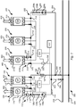
- Fig. 1 schematically illustrates a thermal energy system 400 for distributing heat from a thermal energy circuit 300, to one or several thermal loads 600 such as heating/cooling and/or tap hot water for a building.
- the building may be any type of building suitable for connection to the thermal energy circuit 300, such as a residential building, commercial or office building, an apartment building, a free-standing house or an industrial building.
- the thermal energy circuit 300 may be a district heating grid or a district cooling grid known in the art.
- the district heating grid (or a district cooling grid) may comprise a supply conduit providing heating (or cooling) medium from a thermal plant (not shown) and a return conduit which transport cooled heating medium (or heated cooling medium) to the thermal plant.
- the heating (or cooling) medium may be any fluid suitable for heating (or cooling) at the thermal plant and transported by means of the supply conduit and the return conduit, such as water.
- the thermal fluid may further comprise antifreeze components such as glycol and/or bioethanol, which may allow greater temperature variations of the thermal fluid.
- the heating (or cooling) medium will henceforth be referred to as "thermal fluid".
- the thermal plant may be a geothermal plant, an electrically powered plant for heating (or cooling) fluids, wind or solar plants, or may be driven by combustion of fuels, such as gas or oil.
- the thermal plant is configured to heat (or cool) the thermal fluid and pump it through the thermal energy circuit 300.
- the supply conduit is considered as a hot conduit 302 and the return conduit is considered as a cold conduit 304.
- the supply conduit is considered as a cold conduit 304 and the return conduit is considered as a hot conduit 302.
- the thermal energy circuit 300 may be a combined district heating and cooling grid as previously disclosed in, e.g., WO 2017/076868 filed by E.ON Sverige AB.
- the hot and cold conduits 302 and 304 are not to be seen as supply and return conduits but instead to be seen as the hot conduit and the cold conduit 304 as disclosed in WO 2017/076868 .
- the thermal energy circuit 300 comprises a hot conduit 302 and a cold conduit 304 for distributing thermal energy to/between thermal energy systems 400 connected thereto.
- the thermal energy system 400 is configured to extract/deposit heat from/to the thermal fluid of thermal energy circuit 300 by means of a plurality of heat pump assemblies 100 and a plurality of cooling machine assemblies 200.
- Each of the heat pump assemblies 100 and/or of the cooling machine assemblies 200 can serve one building or a plurality of buildings.
- a specific building may comprise one heat pump assembly 100/one cooling machine assembly 200.
- a specific building may comprise more than one heat pump assembly 100 and cooling machine 200 respectively.
- Each thermal load 600 may be formed in a number of ways, for instance via water-water heating, water-air heating etc. Moreover, in a heat pump assembly 100, a thermal load 600 may be constituted not only by space heating but also e.g. by provision of tap hot water.
- the cooling machine 200 may be configured to meet thermal loads 600 constituted by comfort cooling, to provide cooling to office equipment such as server rooms etc. and/or for cooling of water just to name a few examples.
- Each of the thermal loads 600 may change dynamically which naturally affects the heat pump assemblies 100 and the cooling machine assemblies 200. For instance, the thermal output required from a heat pump assembly 100 or from a cooling machine assembly 200 to maintain a certain preferred indoor temperature of the building 600 may rapidly change with changes in weather. Regardless of the conditions under which the heat pump assemblies 100 and the cooling machine assemblies 200 respectively are subjected to, it is desired that the thermal energy system 400 as a whole operates as efficiently as possible. I.e. that the total electric power consumption thereof is maintained as low as possible for a given operating condition.
- the heat pump assemblies 100 and the cooling machine assemblies 200 shown in Fig. 1 are connected to a thermal heating circuit 102 and to a thermal cooling circuit 202 respectively both comprised in the thermal energy system 400.
- the thermal heating circuit 102 is connected to the thermal energy circuit 300 via a thermal heating circuit inlet 104 connected to the hot conduit 302 and by a thermal heating outlet 106 connected to the cold conduit 304.
- the thermal heating circuit inlet 104 draws thermal fluid from the hot conduit 302 and the thermal heating circuit outlet 106 returns thermal fluid to the cold conduit 304 having extracted heat therefrom, thus returning thermal fluid having a lower temperature.
- the thermal cooling circuit 202 is connected to the thermal energy circuit 300 via a thermal cooling circuit inlet 204 connected to the cold conduit 304 and by a thermal cooling outlet 206 connected to the hot conduit 304.
- the thermal cooling circuit inlet 204 draws thermal fluid from the cold conduit 304 and the thermal cooling circuit outlet 206 returns thermal fluid to the hot conduit 304 having deposited heat therein, thus returning thermal fluid having a higher temperature.
- thermal heating circuit 102 and the thermal cooling circuit 202 are also connected to each other such that thermal fluid can circulate from the thermal cooling circuit outlet 206 to the thermal heating circuit inlet 104 and from the thermal heating circuit outlet 106 to the thermal cooling circuit inlet 204. I.e. thermal fluid may be circulated directly between the thermal heating circuit 102 and the thermal cooling circuit 202.
- the thermal energy system 400 may be connected to the thermal energy circuit 300 by means of a hot connection conduit 402 which connects the hot conduit 302 with the heating circuit inlet 104 and the cooling circuit outlet 206 and by means of a cold connection conduit 404 which connects the cold conduit 304 with the cooling circuit inlet 204 and the heating circuit outlet 106. Further still, the hot connection conduit 402 and the cold connection conduit 404 may be provided with a thermal fluid inlet control valve 406 and with a thermal fluid outlet control valve 408 respectively. The control valves 406, 408 being configured to control the flow and/or pressures of thermal fluid to/from the thermal energy circuit 300.
- the thermal heating circuit flow controller 108 preferably comprises a thermal heating circuit circulation pump 108a and may further comprise a first and optionally a second thermal heating circuit control valve 108b, 108c.
- each heat pump assembly 100 comprises a heat pump 110.
- the heat pumps 110 are configured to extract heat from the thermal fluid distributed from the thermal energy circuit 300 by the thermal heating circuit 102. While only two heat pump assemblies 100 are shown in Fig. 1 , it is to be understood that also three or more heat pump assemblies 100 could be connected to the thermal heating circuit 102.
- Each heat pump 110 may comprise a heat extraction side 110a and a heat releasing side 110b.
- the heat extraction side 110a is connected to a respective heat pump circuit 112.
- the heat pump circuit 112 is in turn connected to the thermal heating circuit 102 via a heat pump circuit inlet 114 at a first connection point 118 and via a heat pump circuit outlet 116 at a second connection point 120.
- Each heat pump circuit 112 and the thermal heating circuit 102 partially overlap, such that the overlap is between the first 118 and second 120 connection points.
- Each heat pump circuit 112 further comprises a heat pump control pump 122 configured to control the flow rate of thermal fluid from the heat pump circuit inlet 114 through the heat pump 110 heat extraction side 110a. It is to be realized that while in Fig. 1 only one heat pump assembly 100 is shown being provided with a heat pump control pump 122, each heat pump assembly 100 may be provided with a heat pump control pump 122.
- the thermal cooling circuit flow controller 208 preferably comprises a thermal cooling circuit circulation pump 208a and it may further comprise a first and optionally a second thermal cooling circuit control valve 208b, 208c.
- each cooling machine assembly 200 comprises a cooling machine 210.
- the cooling machine 210 is configured to deposit heat into the thermal fluid distributed from the thermal energy circuit 300 by the thermal cooling circuit 202. While three cooling machine assemblies 200 are shown in Fig. 1 , it is to be understood that two or more cooling machines assemblies 200 may be connected to the thermal cooling circuit 202.
- Each cooling machine 210 may comprise a heat extraction side 210a and a heat releasing side 210b.
- the heat releasing side 210b is connected to a respective cooling machine circuit 212.
- Each cooling machine circuit 212 is in turn connected to the thermal cooling circuit 202 via a cooling machine circuit inlet 214 at a first connection point 218 and via a cooling machine circuit outlet 216 at a second connection point 220.
- Each cooling machine circuit 212 and the thermal cooling circuit 202 partially overlap, such that the overlap is between the first 218 and second 220 connection points.
- the cooling machine circuit 212 further comprises a cooling machine control pump 222 configured to control the flow rate of thermal fluid from the cooling machine circuit inlet 214 through the cooling machine 210 heat releasing side 210a. It is to be realized that while in Fig. 1 only one cooling machine assembly 200 is shown being provided with a cooling machine control pump 222, each cooling machine assembly 200 may be provided with a cooling machine control pump 222.
- a heat pump assembly controller 124 and a cooling machine assembly controller 224 may be provided to control the heat pump assembly 100 and the cooling machine assembly 200 respectively.
- the respective controller 124, 224 may be configured to control the respective control pump 122, 222 on each heat pump circuit 112 and on each cooling machine circuit 212.
- the respective controller 124, 224 may further be connected to each heat pump 110 and to each cooling machine 210 for control thereof and for monitoring the performance thereof such as the power consumption and/or the thermal load 600 thereof.
- the heat pump assembly controller 124 and/or the cooling machine assembly controller 224 may be formed as a part or a function of a central controller 500 and/or be separate units connected thereto. Further still, the heat pump assembly controller 124 and/or the cooling machine assembly controller 224 may be connected to the thermal heating circuit flow controller 108 and the thermal cooling circuit flow controller 208 respectively.
- a heating circuit outlet temperature sensor 126 and a cooling circuit outlet temperature sensor 226 are provided on the thermal heating circuit outlet 106 and on the thermal cooling circuit outlet 206 respectively.
- the respective temperature sensor 126, 226 is configured to detect the temperature of the thermal fluid in the conduit 106, 206 to which it is attached.
- the heating circuit outlet temperature sensor 126 being connected to the heat pump assembly controller 124 and the cooling circuit outlet temperature sensor 226 being connected to the cooling machine assembly controller 224.
- each heat pump 110 and for each cooling machine 210 it is desired to achieve as high a coefficient of performance (COP) as possible for each heat pump 110 and for each cooling machine 210.
- COP coefficient of performance
- the efficiency of the entire thermal energy system 400 is determined by more than the COP of each heat pump 110 and/or of each cooling machine 210.
- the electric power required by all other energy consuming devices of the thermal energy system 400 must be considered.
- the heat pump control pump 122, the cooling machine control pump 222, the thermal heating circuit controller 108 and the thermal cooling circuit controller 208 requires power in order to achieve the required flow and thus affects the overall efficiency/COP of the thermal energy system 400.
- each heat pump assembly 100 and each cooling machine assembly 200 connected to the thermal energy system 400 affects one another and it is consequently desired to find a way to take improve the overall efficiency of the entire thermal energy system 400.
- the provided central controller 500 is thus configured to control the thermal energy system 400, more specifically the thermal heating circuit flow controller 108 and the thermal cooling circuit flow controller 208 in response to the total electric power consumption of the thermal energy system 400.
- the central controller 500 is configured to alter the temperature of the thermal fluid in the thermal heating circuit outlet 106 and in the thermal cooling circuit outlet 206 respectively, as may be measured by temperature sensors 126, 226.
- the altering of the temperature in the respective outlet 106, 206 is achieved by controlling the respective heating/cooling circuit flow controller 108, 208 which changes the flow rate of thermal fluid in the heating circuit 102 and in the cooling circuit 202 respectively.
- a change in the flow rate of thermal fluid in the heating circuit 102 and in the cooling circuit 202 affects the heat pump assemblies 100 and cooling machine assemblies 200 connected thereto. These will adapt to the new flow rate and a change in electrical power consumption of the thermal energy system 400 can then be determined by the central controller 500.
- the goal of the control of the thermal energy system 400 by the central controller 500 is to reduce total electrical power consumption thereof
- the conditions under which the thermal energy system 400 operates are dynamic. I.e. the thermal loads 600 are constantly subject to change which means that a certain flow rate in the thermal heating circuit 102 and in the thermal cooling circuit 202 does not always result in the same efficiency of the thermal energy system 400 nor in the same respective outlet temperature of the thermal fluid.
- the central controller 500 thus periodically/continuously iterates the control of the thermal energy system 400 to keep the thermal fluid temperature in the heating circuit outlet 106 and in the cooling circuit outlet 206 respectively such that the electric power consumption of the thermal energy system 400 is optimized/reduced for any operating condition/thermal load 600.
- the central controller 500 may be connected, either directly or via the heating pump assembly controller 124 and the assembly controller 224 respectively, to the heating circuit controller 108 and to the cooling circuit controller 208.
- the central controller 500 may further be connected, either directly or via the heating pump assembly controller 124 and the assembly controller 224 respectively, to each heat pump 110 and to each cooling machine 210.
- the central controller 500 may furthermore be connected, either directly or via the heating pump assembly controller 124 and the assembly controller 224 respectively, to the heating circuit outlet temperature sensor 126 and to the cooling circuit outlet temperature sensor 226.
- the central controller 500 may be connected, directly or indirectly, to each component of the thermal energy system 400 that requires.
- the central controller 500 may thus collect power consumption data indicating a total power consumption of the thermal energy system 400.
- Fig. 2 shows another embodiment of the thermal energy system 400, in which the thermal heating circuit 108 and the thermal cooling circuit 208 are not connected directly to each other.
- the embodiment shown in Fig. 2 is in other respects identical to that shown in Fig. 1 .
- the thermal heating circuit inlet 104 connects to the hot conduit 302 of the thermal energy circuit 300 and the thermal heating circuit outlet 106 connects to the cold circuit 302.
- the thermal cooling circuit inlet 204 connects to the cold conduit 304, while the thermal cooling circuit outlet 106 connects to the hot conduit 302.
- heating circuit inlet 104 and the cooling circuit inlet 204 may be provided with a thermal fluid inlet control valve 406.
- the heating circuit outlet 106 and cooling circuit outlet 206 may be provided with a thermal fluid outlet control valve 408.
- the control valves 406, 408 being configured to control the flow and/or pressures of thermal fluid to/from the thermal energy circuit 300.
- the thermal heating circuit 102 and the thermal cooling circuit 202 can be controlled entirely independently of each other as they are only connected to each other via the thermal energy circuit 300.
- FIG. 3 is a schematic illustration of the central controller 500 shown.
- the central controller 500 configured to carry out overall control of functions and operations of the thermal energy system 400, and thus comprises a circuitry 510 which may be associated with a memory 508.
- the circuitry 510 may include a control circuit 502 and an associated processor 504, such as a central processing unit (CPU), microcontroller, or microprocessor.
- the processor 504 is configured to execute program code stored in the memory 508, in order to carry out functions and operations of the central controller 500.
- the memory 508 may be one or more of a buffer, a flash memory, a hard drive, a removable media, a volatile memory, a non-volatile memory, a random access memory (RAM), or another suitable device.
- the memory 508 may include a non-volatile memory for long term data storage and a volatile memory that functions as system memory for the central controller 500.
- the memory 508 may exchange data with the control circuit 502 over a data bus. Accompanying control lines and an address bus between the memory 508 and the control circuit 502 also may be present.
- the circuitry 510 may further comprise a transceiver 506, connected to the control circuit 502, configured to allow remote control and communication between units of the thermal energy system 400.
- a unit of an assembly may be a control pump 122, 222, a valve, a heat pump 110, a cooling machine 210, a flow controller 108, 208, a temperature sensor 126, 226 etc.
- the communication path over which the communication is made may be wired or wireless.
- the communication may include data transfers, and the like. Data transfers may include, but are not limited to, downloading and/or uploading data and receiving or sending messages.
- the data may be processed by the processor 504.
- the processing may include storing the data in a memory, e.g. the memory 508 of the circuitry 510, executing operations or functions, and so forth.
- the communication may be individual for each unit of the respective assembly.
- Functions and operations of the central controller 500 may be embodied in the form of executable logic routines (e.g., lines of code, software programs, etc.) that are stored on a non-transitory computer readable medium (e.g., the memory 508) of the circuitry 510 and are executed by the control circuit 502 (e.g., using the processor 504).
- the functions and operations of the central controller 500 may be a stand-alone software application or form a part of a software application that carries out additional tasks related to the central controller 500.
- the described functions and operations may be considered a method that the corresponding device is configured to carry out.
- the heat pump controller 124 and the cooling machine controller 224 may be formed in a similar manner as the central controller 500.
- the heat pump controller 124 and the cooling machine controller 224 are integral to the central controller 500 and thus comprised, either as physical units or as functions, in said central controller 500 which may then be connected directly to components of each heat pump assembly 100 and of each cooling machine assembly 200.
- the central controller 500 is configured for controlling power consumption in a thermal energy system 400 comprising a plurality of heat pump assemblies 100, each heat pump assembly 100 being connected to a thermal energy circuit 300 comprising a hot conduit 302 and a cold conduit 304 via a thermal heating circuit inlet 104 connected to the hot conduit 302 and via a thermal heating circuit outlet 106 connected to the cold conduit 304.
- the heat pump assembly further comprises a thermal heating circuit flow controller 108 configured to control a flow of thermal fluid from the thermal heating circuit inlet 104 to the thermal heating circuit outlet 106.
- the thermal energy system 400 further comprises a plurality of cooling machine assemblies 200, each cooling machine assembly 200 being connected to the thermal energy circuit 300 via a thermal cooling circuit inlet 204 connected to the cold conduit 304 and via a thermal cooling circuit outlet 206 connected to the hot conduit 302 and comprises a thermal cooling circuit flow controller 208 configured to control a flow of thermal fluid from the thermal cooling circuit inlet 204 to the thermal cooling circuit outlet 206.
- the central controller transceiver 506 is configured to receive power consumption data pertaining to the plurality of heat pump assemblies 100 and the plurality of cooling assemblies 200.
- the power consumption data may be formed by a signal from each of, or from components thereof, the heat pump assemblies 100 and the cooling machine assemblies 200 and/or from the heat pump assembly controller 124 and the cooling machine assembly controller 224. It may further be a signal indicating the electrical power consumption of each heat pump 110, each cooling machine 210, each heat pump control pump 122, each cooling machine control pump 222, each heating circuit flow controller 108 and of each cooling circuit flow controller 208. It may comprise the total electric power consumption the thermal energy system 400.
- the central controller 500 is configured to transmit a heating circuit control signal to the thermal heating circuit flow controller 108, the heating circuit control signal being indicative of a heating circuit outlet temperature in the thermal heating circuit outlet 106.
- the central controller 500 further being configured to transmit a cooling circuit control signal to the thermal cooling circuit flow controller 208, the control signal being indicative of a cooling circuit outlet temperature in the thermal cooling circuit outlet 206.
- the central controller circuitry 510 is configured to execute an outlet temperature setting function configured to periodically alter the heating circuit outlet temperature and the cooling circuit outlet temperature.
- the respective thermal fluid outlet temperatures are altered by controlling the thermal heating circuit flow controller 108 and the thermal cooling circuit flow controller 208, thus altering the flow rate of thermal fluid in the thermal heating circuit 102 and in the thermal cooling circuit 202 respectively.
- a decrease in the flow rate of thermal fluid in the thermal heating circuit 102 will cause a decrease in the temperature of the thermal fluid in the heating circuit outlet 106 and vice versa.
- a decrease in the flow rate of thermal fluid in the thermal cooling circuit 202 will cause an increase in the temperature of the thermal fluid in the cooling circuit outlet 206 and vice versa.
- the central controller 500 may receive feedback from the respective outlet temperature sensor 126, 226 for achieving the desired temperature of the thermal fluid in the thermal heating circuit outlet 106 and in the thermal cooling circuit outlet 206 respectively.
- the central controller 500 further comprises an analyzing function, implemented and executed by the circuitry 502, configured to, based on the power consumption data, determine a present total power consumption of the plurality of heat pump assemblies 100 and the plurality of cooling machine assemblies 200.
- the outlet temperature setting function is further configured to increase or decrease the heating circuit outlet temperature and the cooling circuit outlet temperature based on a change between a previously determined total power consumption and the determined present total power consumption.
- temperature setting function is configured to set the heating circuit outlet temperature and the cooling circuit outlet temperature to a fixed value for a predetermined period of time.
- the thermal energy system 400 will thus have time to stabilize, with each heat pump assembly 100 and each cooling machine assembly 200, finding a new equilibrium or balance in which each heat pump control pump 122, each cooling machine control pump 222, each heat pump 110 and each cooling machine 210 adapts to the new flow rate of thermal fluid in the thermal heating circuit 102 and in the thermal cooling circuit 202 respectively.
- the period of time which each temperature is set for may be determined by a set time period such as 30 to 120 seconds. It may also be determined by when the total electrical power consumption stabilizes after a change in the temperature of the thermal fluid in either of the thermal heating circuit outlet 106 or in the thermal cooling circuit outlet 206.
- the temperature in the thermal heating circuit outlet 106 may, as mentioned, be measured by means of the heating circuit outlet temperature sensor 126 and the temperature in the thermal cooling circuit outlet 206 may, as mentioned, be measured by means of the cooling circuit outlet temperature sensor 226.
- the heating circuit outlet temperature is configured to be set to between -8 °C and 50 °C and the cooling circuit outlet temperature is configured to be set to between -4 °C and 60 °C
- Fig. 4 a schematic flowchart of a method 1000 for controlling the power consumption of a thermal energy system 400 is shown.
- the method comprises altering 1002 the heating circuit outlet temperature and the cooling circuit outlet temperature.
- the method 1000 is initiated either by an alteration 1002 of the temperature of the thermal fluid in the thermal heating circuit outlet 106 and/or in the thermal cooling circuit outlet 206, or by determining 1004 a present power consumption of the thermal energy system 400 followed by an alteration 1002 of the outlet temperature. Thereafter can a change between the present total power consumption and a previously determined total power consumption of the thermal energy system 400 be determined 1004.
- the method 1000 comprises awaiting 1006 a new thermal energy system 400 balance before the present total power consumption is determined 1004, as is described above.
- the time period that is required before a present total power consumption is determined 1004 can be defined by a set, predetermined, time period, preferably between 30 and 120 seconds. It may also be determined by when the total power consumption of the thermal energy system 400 stabilizes after that the new outlet temperature has been set, whereby the present total power consumption can be determined 1004 as the stabilized total power consumption.
- a stabilized electrical power consumption can be defined as an electrical power consumption that has reached a sufficiently low degree of change per time unit in electrical power consumption after an altered outlet temperature.
- the temperature in the thermal heating circuit outlet 106 and/or in the thermal cooling circuit outlet 206 is then increased 1002a or decreased 1002b.
- the method 1000 may further comprise that, if the change in total electric power consumption is determined 1004 to be a decrease from the previously determined total power consumption, the heating circuit outlet temperature is further decreased 1002b if the previous altering 1002 of the heating outlet temperature was a decrease. The heating circuit outlet temperature may then also be further increased 1002a if the previous altering of the heating circuit outlet temperature was an increase which achieved a decrease in total power consumption of the thermal energy system 400.
- the heating circuit outlet temperature may be increased 1002a if the previous altering 1002 of the heating circuit outlet temperature was a decrease and the heating circuit outlet temperature may be decreased 1002b if the previous altering 1002 of the heating circuit outlet temperature was an increase.
- the cooling circuit outlet temperature is further decreased 1002b if the previous altering 1002 of the heating outlet temperature was a decrease.
- the cooling circuit outlet temperature may be further increased 1002a if the previous altering of the cooling circuit outlet temperature was an increase.
- the cooling circuit outlet temperature be increased 1002a if the previous altering 1002 of the cooling outlet temperature was a decrease.
- the heating circuit outlet temperature may be decreased 1002a if the previous altering 1002 of the cooling circuit outlet temperature was an increase.
- the method shown in Fig. 4 may be performed for the heating circuit 102 and the cooling circuit 202 independently, i.e. controlling the temperature of the thermal fluid in the heating circuit outlet 106 and in the cooling circuit outlet 206 at the same time and/or independently of each other to achieve a reduced total electric power consumption of the thermal energy system 400.
- the heating circuit outlet temperature and the cooling circuit outlet temperature are controlled by changing the flow rate of thermal fluid provided by the thermal heating circuit flow controller 108 and the thermal cooling circuit flow rate controller 208 respectively.
- the heating circuit outlet temperature sensor 126 and the cooling circuit outlet temperature sensor 226 may respectively provide temperature information to the central controller 500 to allow feedback control of the thermal heating circuit flow controller 108 and of the thermal cooling circuit flow controller 208 to achieve the desired outlet temperatures.
- the method 1000 may further comprise determining 1004 that, when an outlet temperature is achieved where both an increase and a decrease in thermal fluid temperature in the thermal heating circuit outlet 106 does not achieve a sufficiently large reduction in total electric power consumption of the thermal energy system 400, to proceed and alter the temperature in the thermal cooling circuit outlet 206 instead.
- the method 1000 is then performed altering the thermal fluid temperature in the thermal cooling circuit outlet 206 until an outlet temperature is achieved, where an increase and a decrease in thermal fluid temperature in the thermal cooling circuit outlet 206 does not achieve a sufficiently large reduction in total electric power consumption for the thermal energy system 400, after which the method 1000 can be repeated.
- Fig. 5 is yet another embodiment of the method 1000 for controlling the power consumption of a thermal energy system 400 shown.
- the method illustrated in Fig. 5 shows how the method 1000 may firstly be performed for the thermal heating circuit 102 such that a thermal fluid temperature in the thermal heating circuit outlet 106 is found which provides a desired reduced total electric power consumption for the thermal heating circuit 102 and all heat pump assemblies 100.
- the method 1000 subsequently proceeds to iterate the method 1000 on the thermal cooling circuit 202, thus achieving a temperature of the thermal fluid in the thermal cooling circuit outlet 206 which achieves a desired reduced total electric power consumption for the thermal cooling circuit 102 and all cooling machine assemblies 200.
- the method 1000 may then be performed again for the thermal heating circuit 102 etc.
Landscapes
- Engineering & Computer Science (AREA)
- Chemical & Material Sciences (AREA)
- Combustion & Propulsion (AREA)
- Mechanical Engineering (AREA)
- General Engineering & Computer Science (AREA)
- Physics & Mathematics (AREA)
- Thermal Sciences (AREA)
- Signal Processing (AREA)
- Fuzzy Systems (AREA)
- Mathematical Physics (AREA)
- Human Computer Interaction (AREA)
- Air Conditioning Control Device (AREA)
- Steam Or Hot-Water Central Heating Systems (AREA)
Priority Applications (3)
| Application Number | Priority Date | Filing Date | Title |
|---|---|---|---|
| EP20183771.3A EP3933281A1 (fr) | 2020-07-02 | 2020-07-02 | Contrôle de la consommation d'énergie dans un système d'énergie thermique |
| CN202110708627.2A CN113883662B (zh) | 2020-07-02 | 2021-06-25 | 热能系统中的功率消耗的控制 |
| US17/304,887 US11644199B2 (en) | 2020-07-02 | 2021-06-28 | Controlling power consumption in a thermal energy system |
Applications Claiming Priority (1)
| Application Number | Priority Date | Filing Date | Title |
|---|---|---|---|
| EP20183771.3A EP3933281A1 (fr) | 2020-07-02 | 2020-07-02 | Contrôle de la consommation d'énergie dans un système d'énergie thermique |
Publications (1)
| Publication Number | Publication Date |
|---|---|
| EP3933281A1 true EP3933281A1 (fr) | 2022-01-05 |
Family
ID=71465097
Family Applications (1)
| Application Number | Title | Priority Date | Filing Date |
|---|---|---|---|
| EP20183771.3A Pending EP3933281A1 (fr) | 2020-07-02 | 2020-07-02 | Contrôle de la consommation d'énergie dans un système d'énergie thermique |
Country Status (3)
| Country | Link |
|---|---|
| US (1) | US11644199B2 (fr) |
| EP (1) | EP3933281A1 (fr) |
| CN (1) | CN113883662B (fr) |
Cited By (2)
| Publication number | Priority date | Publication date | Assignee | Title |
|---|---|---|---|---|
| WO2023237671A1 (fr) * | 2022-06-10 | 2023-12-14 | Grundfos Holding A/S | Optimisation d'énergie d'un système de transport de chaleur |
| EP4350234A1 (fr) * | 2022-10-03 | 2024-04-10 | Renson Ventilation | Système de chauffage et/ou de refroidissement pour unités de logement collectif résidentiel, dispositif de commande associé et procédé de commande associé |
Families Citing this family (5)
| Publication number | Priority date | Publication date | Assignee | Title |
|---|---|---|---|---|
| WO2019222830A1 (fr) * | 2018-05-19 | 2019-11-28 | Gestion Martin Larocque Inc. | Système de récupération de chaleur pour chauffer, par exemple, des serres |
| EP3865778A1 (fr) * | 2020-02-13 | 2021-08-18 | E.ON Sverige AB | Ensemble d'énergie thermique |
| CN116772370A (zh) * | 2022-03-09 | 2023-09-19 | 开利公司 | 混合热系统、其能力分配控制方法、可读存储介质及控制系统 |
| EP4573322A1 (fr) * | 2022-08-16 | 2025-06-25 | Qvantum Industries AB | Procédé de commande d'un fonctionnement d'un agencement de transfert de chaleur fluide-fluide modulaire et agencement de transfert de chaleur fluide-fluide modulaire |
| US20240310079A1 (en) * | 2023-03-13 | 2024-09-19 | EcoSmart Solution, L.L.C. | Dual loop heat exchanger using geothermal resource |
Citations (6)
| Publication number | Priority date | Publication date | Assignee | Title |
|---|---|---|---|---|
| EP2469238A2 (fr) * | 2010-12-21 | 2012-06-27 | Logotherm Regelsysteme GmbH | Installation photovoltaïque |
| US20130284818A1 (en) * | 2011-08-24 | 2013-10-31 | Panasonic Corporation | Heating system control method and heating system |
| EP3018422A1 (fr) * | 2013-07-03 | 2016-05-11 | Panasonic Intellectual Property Management Co., Ltd. | Dispositif de commande de pompe à chaleur et procédé de commande pour dispositif de commande de pompe à chaleur |
| WO2017076868A1 (fr) | 2015-11-04 | 2017-05-11 | E.On Sverige Ab | Système de distribution d'énergie thermique de quartier |
| EP3591298A1 (fr) * | 2018-07-03 | 2020-01-08 | E.ON Sverige AB | Système de chauffage thermique et son organe de commande |
| US20200049381A1 (en) * | 2018-08-08 | 2020-02-13 | Thielmann Ventures Ltd. | Passive energy loop system and method |
Family Cites Families (7)
| Publication number | Priority date | Publication date | Assignee | Title |
|---|---|---|---|---|
| US7216698B2 (en) * | 2001-05-16 | 2007-05-15 | Uniflair S.P.A. | Air-conditioning system |
| US7010392B2 (en) * | 2004-05-26 | 2006-03-07 | Hewlett-Packard Development Company, L.P. | Energy efficient CRAC unit operation using heat transfer levels |
| JP5320128B2 (ja) * | 2009-03-31 | 2013-10-23 | アズビル株式会社 | 送水温度制御装置および方法 |
| US8901769B2 (en) * | 2009-07-30 | 2014-12-02 | Lutron Electronics Co., Inc. | Load control system having an energy savings mode |
| KR101566735B1 (ko) * | 2013-12-05 | 2015-11-06 | 현대자동차 주식회사 | 하이브리드 차량의 실내 난방 방법 및 장치 |
| JP6235937B2 (ja) * | 2014-03-12 | 2017-11-22 | アズビル株式会社 | 熱源機器制御装置および空調システム |
| MX2018005675A (es) * | 2015-11-04 | 2018-11-09 | E On Sverige Ab | Montaje de consumo local de energia termica y montaje de generador local de energia termica para un sistema de distribucion regional de energia termica. |
-
2020
- 2020-07-02 EP EP20183771.3A patent/EP3933281A1/fr active Pending
-
2021
- 2021-06-25 CN CN202110708627.2A patent/CN113883662B/zh active Active
- 2021-06-28 US US17/304,887 patent/US11644199B2/en active Active
Patent Citations (6)
| Publication number | Priority date | Publication date | Assignee | Title |
|---|---|---|---|---|
| EP2469238A2 (fr) * | 2010-12-21 | 2012-06-27 | Logotherm Regelsysteme GmbH | Installation photovoltaïque |
| US20130284818A1 (en) * | 2011-08-24 | 2013-10-31 | Panasonic Corporation | Heating system control method and heating system |
| EP3018422A1 (fr) * | 2013-07-03 | 2016-05-11 | Panasonic Intellectual Property Management Co., Ltd. | Dispositif de commande de pompe à chaleur et procédé de commande pour dispositif de commande de pompe à chaleur |
| WO2017076868A1 (fr) | 2015-11-04 | 2017-05-11 | E.On Sverige Ab | Système de distribution d'énergie thermique de quartier |
| EP3591298A1 (fr) * | 2018-07-03 | 2020-01-08 | E.ON Sverige AB | Système de chauffage thermique et son organe de commande |
| US20200049381A1 (en) * | 2018-08-08 | 2020-02-13 | Thielmann Ventures Ltd. | Passive energy loop system and method |
Cited By (3)
| Publication number | Priority date | Publication date | Assignee | Title |
|---|---|---|---|---|
| WO2023237671A1 (fr) * | 2022-06-10 | 2023-12-14 | Grundfos Holding A/S | Optimisation d'énergie d'un système de transport de chaleur |
| EP4350234A1 (fr) * | 2022-10-03 | 2024-04-10 | Renson Ventilation | Système de chauffage et/ou de refroidissement pour unités de logement collectif résidentiel, dispositif de commande associé et procédé de commande associé |
| BE1030935B1 (nl) * | 2022-10-03 | 2024-04-29 | Renson Ventilation Nv | Een verwarmings- en/of koelingssysteem voor collectieve residentiële wooneenheden, een sturingsinrichting daarvoor en een werkwijze voor het aansturen daarvan |
Also Published As
| Publication number | Publication date |
|---|---|
| US11644199B2 (en) | 2023-05-09 |
| US20220003429A1 (en) | 2022-01-06 |
| CN113883662B (zh) | 2025-11-04 |
| CN113883662A (zh) | 2022-01-04 |
Similar Documents
| Publication | Publication Date | Title |
|---|---|---|
| US11644199B2 (en) | Controlling power consumption in a thermal energy system | |
| US11644214B2 (en) | Hydronic building systems control | |
| US10746480B2 (en) | Plural heat pump and thermal storage system for facilitating power shaping services on the electrical power grid at consumer premises | |
| EP3622224B1 (fr) | Systèmes de distribution d'énergie urbain | |
| JP2018534525A (ja) | ヒートポンピングの方法およびシステム | |
| US20200049381A1 (en) | Passive energy loop system and method | |
| US20120298204A1 (en) | Energy saving system and method for heating water | |
| EP2394099A1 (fr) | Commande d'une sous-station de chauffage de district | |
| EP2450641B1 (fr) | Installation pour la récupération de chaleur de l'air d'évacuation utilisant une pompe à chaleur, et bâtiment comportant cette installation | |
| CN216620197U (zh) | 一种中央空调风水联动控制系统 | |
| US12467636B2 (en) | Thermal energy assembly | |
| EP3901525A1 (fr) | Système de distribution d'énergie locale, ensemble d'extraction de chaleur locale et procédés de commande associés | |
| CN103003636A (zh) | 用于运行太阳能设备的方法 | |
| EP2685176A1 (fr) | Appareil et procédé pour influencer la température dans un bâtiment | |
| US12152791B2 (en) | Efficiency for a heat extracting system and/or a heat depositing system | |
| CN118935811A (zh) | 一种双源双效热泵机组运行控制方法及系统 | |
| CN110878973B (zh) | 建筑复合能源装置的优化调适方法及装置 | |
| EP3864486B1 (fr) | Système de distribution d'énergie thermique et procédé associé | |
| JP6111871B2 (ja) | デマンドレスポンスシステム | |
| WO2021205400A1 (fr) | Pompe à chaleur géothermique désertique intelligente pour climatisation et refroidissement de l'eau domestique | |
| CN119958079B (zh) | 一种适用于不同季节的冷热源供水机组及其控制方法 | |
| US20240151411A1 (en) | Thermal Liquid Battery | |
| WO2025176573A1 (fr) | Procédé de commande d'un système de pompe à chaleur décentralisé pour fournir un chauffage à une zone intérieure d'un ou de plusieurs bâtiments | |
| CN203489423U (zh) | 一种基于在线管理的中央空调远程管理系统 |
Legal Events
| Date | Code | Title | Description |
|---|---|---|---|
| PUAI | Public reference made under article 153(3) epc to a published international application that has entered the european phase |
Free format text: ORIGINAL CODE: 0009012 |
|
| STAA | Information on the status of an ep patent application or granted ep patent |
Free format text: STATUS: THE APPLICATION HAS BEEN PUBLISHED |
|
| AK | Designated contracting states |
Kind code of ref document: A1 Designated state(s): AL AT BE BG CH CY CZ DE DK EE ES FI FR GB GR HR HU IE IS IT LI LT LU LV MC MK MT NL NO PL PT RO RS SE SI SK SM TR |
|
| B565 | Issuance of search results under rule 164(2) epc |
Effective date: 20201211 |
|
| STAA | Information on the status of an ep patent application or granted ep patent |
Free format text: STATUS: REQUEST FOR EXAMINATION WAS MADE |
|
| 17P | Request for examination filed |
Effective date: 20220324 |
|
| RBV | Designated contracting states (corrected) |
Designated state(s): AL AT BE BG CH CY CZ DE DK EE ES FI FR GB GR HR HU IE IS IT LI LT LU LV MC MK MT NL NO PL PT RO RS SE SI SK SM TR |
|
| STAA | Information on the status of an ep patent application or granted ep patent |
Free format text: STATUS: EXAMINATION IS IN PROGRESS |
|
| 17Q | First examination report despatched |
Effective date: 20240202 |