EP3933480A1 - Medizinisches beobachtungssystem - Google Patents
Medizinisches beobachtungssystem Download PDFInfo
- Publication number
- EP3933480A1 EP3933480A1 EP20779512.1A EP20779512A EP3933480A1 EP 3933480 A1 EP3933480 A1 EP 3933480A1 EP 20779512 A EP20779512 A EP 20779512A EP 3933480 A1 EP3933480 A1 EP 3933480A1
- Authority
- EP
- European Patent Office
- Prior art keywords
- captured image
- imaging unit
- subject distance
- image
- medical observation
- Prior art date
- Legal status (The legal status is an assumption and is not a legal conclusion. Google has not performed a legal analysis and makes no representation as to the accuracy of the status listed.)
- Withdrawn
Links
Images









Classifications
-
- G—PHYSICS
- G02—OPTICS
- G02B—OPTICAL ELEMENTS, SYSTEMS OR APPARATUS
- G02B7/00—Mountings, adjusting means, or light-tight connections, for optical elements
- G02B7/28—Systems for automatic generation of focusing signals
- G02B7/36—Systems for automatic generation of focusing signals using image sharpness techniques, e.g. image processing techniques for generating autofocus signals
-
- A—HUMAN NECESSITIES
- A61—MEDICAL OR VETERINARY SCIENCE; HYGIENE
- A61B—DIAGNOSIS; SURGERY; IDENTIFICATION
- A61B1/00—Instruments for performing medical examinations of the interior of cavities or tubes of the body by visual or photographical inspection, e.g. endoscopes; Illuminating arrangements therefor
- A61B1/00163—Optical arrangements
- A61B1/00193—Optical arrangements adapted for stereoscopic vision
-
- A—HUMAN NECESSITIES
- A61—MEDICAL OR VETERINARY SCIENCE; HYGIENE
- A61B—DIAGNOSIS; SURGERY; IDENTIFICATION
- A61B1/00—Instruments for performing medical examinations of the interior of cavities or tubes of the body by visual or photographical inspection, e.g. endoscopes; Illuminating arrangements therefor
- A61B1/04—Instruments for performing medical examinations of the interior of cavities or tubes of the body by visual or photographical inspection, e.g. endoscopes; Illuminating arrangements therefor combined with photographic or television appliances
- A61B1/045—Control thereof
-
- A—HUMAN NECESSITIES
- A61—MEDICAL OR VETERINARY SCIENCE; HYGIENE
- A61B—DIAGNOSIS; SURGERY; IDENTIFICATION
- A61B90/00—Instruments, implements or accessories specially adapted for surgery or diagnosis and not covered by any of the groups A61B1/00 - A61B50/00, e.g. for luxation treatment or for protecting wound edges
- A61B90/20—Surgical microscopes characterised by non-optical aspects
-
- G—PHYSICS
- G02—OPTICS
- G02B—OPTICAL ELEMENTS, SYSTEMS OR APPARATUS
- G02B21/00—Microscopes
- G02B21/0004—Microscopes specially adapted for specific applications
- G02B21/0012—Surgical microscopes
-
- G—PHYSICS
- G02—OPTICS
- G02B—OPTICAL ELEMENTS, SYSTEMS OR APPARATUS
- G02B21/00—Microscopes
- G02B21/24—Base structure
- G02B21/241—Devices for focusing
- G02B21/244—Devices for focusing using image analysis techniques
-
- G—PHYSICS
- G02—OPTICS
- G02B—OPTICAL ELEMENTS, SYSTEMS OR APPARATUS
- G02B21/00—Microscopes
- G02B21/24—Base structure
- G02B21/241—Devices for focusing
- G02B21/245—Devices for focusing using auxiliary sources, detectors
-
- G—PHYSICS
- G02—OPTICS
- G02B—OPTICAL ELEMENTS, SYSTEMS OR APPARATUS
- G02B21/00—Microscopes
- G02B21/36—Microscopes arranged for photographic purposes or projection purposes or digital imaging or video purposes including associated control and data processing arrangements
- G02B21/365—Control or image processing arrangements for digital or video microscopes
-
- G—PHYSICS
- G02—OPTICS
- G02B—OPTICAL ELEMENTS, SYSTEMS OR APPARATUS
- G02B7/00—Mountings, adjusting means, or light-tight connections, for optical elements
- G02B7/001—Counterbalanced structures, e.g. surgical microscopes
-
- G—PHYSICS
- G02—OPTICS
- G02B—OPTICAL ELEMENTS, SYSTEMS OR APPARATUS
- G02B7/00—Mountings, adjusting means, or light-tight connections, for optical elements
- G02B7/28—Systems for automatic generation of focusing signals
- G02B7/40—Systems for automatic generation of focusing signals using time delay of the reflected waves, e.g. of ultrasonic waves
-
- G—PHYSICS
- G03—PHOTOGRAPHY; CINEMATOGRAPHY; ANALOGOUS TECHNIQUES USING WAVES OTHER THAN OPTICAL WAVES; ELECTROGRAPHY; HOLOGRAPHY
- G03B—APPARATUS OR ARRANGEMENTS FOR TAKING PHOTOGRAPHS OR FOR PROJECTING OR VIEWING THEM; APPARATUS OR ARRANGEMENTS EMPLOYING ANALOGOUS TECHNIQUES USING WAVES OTHER THAN OPTICAL WAVES; ACCESSORIES THEREFOR
- G03B13/00—Viewfinders; Focusing aids for cameras; Means for focusing for cameras; Autofocus systems for cameras
- G03B13/32—Means for focusing
- G03B13/34—Power focusing
- G03B13/36—Autofocus systems
-
- G—PHYSICS
- G03—PHOTOGRAPHY; CINEMATOGRAPHY; ANALOGOUS TECHNIQUES USING WAVES OTHER THAN OPTICAL WAVES; ELECTROGRAPHY; HOLOGRAPHY
- G03B—APPARATUS OR ARRANGEMENTS FOR TAKING PHOTOGRAPHS OR FOR PROJECTING OR VIEWING THEM; APPARATUS OR ARRANGEMENTS EMPLOYING ANALOGOUS TECHNIQUES USING WAVES OTHER THAN OPTICAL WAVES; ACCESSORIES THEREFOR
- G03B15/00—Special procedures for taking photographs; Apparatus therefor
- G03B15/14—Special procedures for taking photographs; Apparatus therefor for taking photographs during medical operations
-
- G—PHYSICS
- G03—PHOTOGRAPHY; CINEMATOGRAPHY; ANALOGOUS TECHNIQUES USING WAVES OTHER THAN OPTICAL WAVES; ELECTROGRAPHY; HOLOGRAPHY
- G03B—APPARATUS OR ARRANGEMENTS FOR TAKING PHOTOGRAPHS OR FOR PROJECTING OR VIEWING THEM; APPARATUS OR ARRANGEMENTS EMPLOYING ANALOGOUS TECHNIQUES USING WAVES OTHER THAN OPTICAL WAVES; ACCESSORIES THEREFOR
- G03B7/00—Control of exposure by setting shutters, diaphragms or filters, separately or conjointly
- G03B7/08—Control effected solely on the basis of the response, to the intensity of the light received by the camera, of a built-in light-sensitive device
- G03B7/091—Digital circuits
- G03B7/095—Digital circuits for control of aperture
-
- H—ELECTRICITY
- H04—ELECTRIC COMMUNICATION TECHNIQUE
- H04N—PICTORIAL COMMUNICATION, e.g. TELEVISION
- H04N23/00—Cameras or camera modules comprising electronic image sensors; Control thereof
- H04N23/50—Constructional details
- H04N23/555—Constructional details for picking-up images in sites, inaccessible due to their dimensions or hazardous conditions, e.g. endoscopes or borescopes
-
- H—ELECTRICITY
- H04—ELECTRIC COMMUNICATION TECHNIQUE
- H04N—PICTORIAL COMMUNICATION, e.g. TELEVISION
- H04N23/00—Cameras or camera modules comprising electronic image sensors; Control thereof
- H04N23/60—Control of cameras or camera modules
- H04N23/62—Control of parameters via user interfaces
-
- H—ELECTRICITY
- H04—ELECTRIC COMMUNICATION TECHNIQUE
- H04N—PICTORIAL COMMUNICATION, e.g. TELEVISION
- H04N23/00—Cameras or camera modules comprising electronic image sensors; Control thereof
- H04N23/60—Control of cameras or camera modules
- H04N23/67—Focus control based on electronic image sensor signals
-
- H—ELECTRICITY
- H04—ELECTRIC COMMUNICATION TECHNIQUE
- H04N—PICTORIAL COMMUNICATION, e.g. TELEVISION
- H04N23/00—Cameras or camera modules comprising electronic image sensors; Control thereof
- H04N23/60—Control of cameras or camera modules
- H04N23/67—Focus control based on electronic image sensor signals
- H04N23/671—Focus control based on electronic image sensor signals in combination with active ranging signals, e.g. using light or sound signals emitted toward objects
-
- H—ELECTRICITY
- H04—ELECTRIC COMMUNICATION TECHNIQUE
- H04N—PICTORIAL COMMUNICATION, e.g. TELEVISION
- H04N23/00—Cameras or camera modules comprising electronic image sensors; Control thereof
- H04N23/60—Control of cameras or camera modules
- H04N23/67—Focus control based on electronic image sensor signals
- H04N23/672—Focus control based on electronic image sensor signals based on the phase difference signals
-
- H—ELECTRICITY
- H04—ELECTRIC COMMUNICATION TECHNIQUE
- H04N—PICTORIAL COMMUNICATION, e.g. TELEVISION
- H04N23/00—Cameras or camera modules comprising electronic image sensors; Control thereof
- H04N23/60—Control of cameras or camera modules
- H04N23/67—Focus control based on electronic image sensor signals
- H04N23/675—Focus control based on electronic image sensor signals comprising setting of focusing regions
-
- H—ELECTRICITY
- H04—ELECTRIC COMMUNICATION TECHNIQUE
- H04N—PICTORIAL COMMUNICATION, e.g. TELEVISION
- H04N23/00—Cameras or camera modules comprising electronic image sensors; Control thereof
- H04N23/70—Circuitry for compensating brightness variation in the scene
- H04N23/71—Circuitry for evaluating the brightness variation
-
- H—ELECTRICITY
- H04—ELECTRIC COMMUNICATION TECHNIQUE
- H04N—PICTORIAL COMMUNICATION, e.g. TELEVISION
- H04N23/00—Cameras or camera modules comprising electronic image sensors; Control thereof
- H04N23/70—Circuitry for compensating brightness variation in the scene
- H04N23/74—Circuitry for compensating brightness variation in the scene by influencing the scene brightness using illuminating means
-
- H—ELECTRICITY
- H04—ELECTRIC COMMUNICATION TECHNIQUE
- H04N—PICTORIAL COMMUNICATION, e.g. TELEVISION
- H04N23/00—Cameras or camera modules comprising electronic image sensors; Control thereof
- H04N23/70—Circuitry for compensating brightness variation in the scene
- H04N23/75—Circuitry for compensating brightness variation in the scene by influencing optical camera components
-
- H—ELECTRICITY
- H04—ELECTRIC COMMUNICATION TECHNIQUE
- H04N—PICTORIAL COMMUNICATION, e.g. TELEVISION
- H04N5/00—Details of television systems
- H04N5/222—Studio circuitry; Studio devices; Studio equipment
- H04N5/2224—Studio circuitry; Studio devices; Studio equipment related to virtual studio applications
- H04N5/2226—Determination of depth image, e.g. for foreground/background separation
-
- G—PHYSICS
- G02—OPTICS
- G02B—OPTICAL ELEMENTS, SYSTEMS OR APPARATUS
- G02B23/00—Telescopes, e.g. binoculars; Periscopes; Instruments for viewing the inside of hollow bodies; Viewfinders; Optical aiming or sighting devices
- G02B23/24—Instruments or systems for viewing the inside of hollow bodies, e.g. fibrescopes
-
- G—PHYSICS
- G02—OPTICS
- G02B—OPTICAL ELEMENTS, SYSTEMS OR APPARATUS
- G02B7/00—Mountings, adjusting means, or light-tight connections, for optical elements
- G02B7/28—Systems for automatic generation of focusing signals
- G02B7/36—Systems for automatic generation of focusing signals using image sharpness techniques, e.g. image processing techniques for generating autofocus signals
- G02B7/38—Systems for automatic generation of focusing signals using image sharpness techniques, e.g. image processing techniques for generating autofocus signals measured at different points on the optical axis, e.g. focussing on two or more planes and comparing image data
Definitions
- the present disclosure relates to a medical observation system.
- the surgical operation microscope described in PTL 1 includes an imaging unit that captures an image of an observation target and a support that moves the imaging unit using movement with six degrees of freedom.
- the surgical operator grasps the imaging unit and uses the movement of six degrees of freedom of the support to position the imaging unit at a position facing the observation target of the patient lying on the operating table.
- the captured image taken by the imaging unit is magnified at a predetermined magnification and displayed on the display device. Then, the surgical operator executes the surgical operation while checking the captured image displayed on the display device.
- the operator's hand, surgical instrument, or the like may enter the angle of view of the imaging unit.
- the brightness of the captured image is adjusted so that the image to be observed becomes darker. That is, the captured image makes it difficult for the operator to recognize the observation target.
- the present disclosure has been made in view of the above, and an object of the present disclosure is to provide a medical observation system capable of generating an image suitable for observation.
- a medical observation system configured with an imaging unit that captures an image of a subject and generates a captured image, a distance information acquiring unit configured to acquire subject distance information regarding a subject distance from a specific position to a corresponding position on the subject, the corresponding position corresponding to each of at least two pixel positions in the captured image, and an operation control section configured to control at least any of the focal position of the imaging unit, the brightness of the captured image, and the depth of field of the imaging unit on the basis of the subject distance information.
- the subject distance information includes depth map information obtained by detecting the subject distance from the specific position to the corresponding position on the subject, the corresponding position corresponding to a pixel position in the captured image, for each of the pixel positions, in the above disclosure.
- the operation control section determines a pixel position of the subject distance that is specific in the captured image, on the basis of the subject distance information, and controls the focal position of the imaging unit such that an area including the determined pixel position is in focus, in the above disclosure.
- the pixel position of the specific subject distance is a pixel position whose subject distance is the largest in the captured image, in the above disclosure.
- the operation control section determines the pixel position of the specific subject distance in the captured image among the pixel positions in a central region including the center of the captured image, on the basis of the subject distance information, and controls the focal position of the imaging unit such that the area including the determined pixel position is in focus, in the above disclosure.
- a detection region setting section configured to set a detection region in the captured image
- an evaluation value calculating section configured to calculate an evaluation value used for at least one of control of the focal position of the imaging unit and control of the brightness of the captured image executed by the operation control section on the basis of the image in the detection region in the captured image
- the detection region setting section determines a range of the subject distance to pay attention to, on the basis of the subject distance information, and sets an area including a pixel position of the subject distance included in the determined range of the subject distance in the captured image as the detection region, in the above disclosure.
- a focal position detecting unit configured to detect the current focal position in the imaging unit is further provided, and the operation control section adjusts the brightness of the captured image on the basis of the subject distance information and the current focal position, in the above disclosure.
- a detection region setting section configured to set a detection region in the captured image
- an evaluation value calculating section configured to calculate an evaluation value used for controlling the brightness of the captured image by the operation control section, on the basis of the image in the detection region in the captured image
- the detection region setting section determines the currently observed region in the captured image on the basis of the subject distance information and the current focal position, and sets the determined region as the detection region, in the above disclosure.
- a focal position detecting unit configured to detect a current focal position in the imaging unit
- the operation control section controls the depth of field of the imaging unit on the basis of the subject distance information and the current focal position.
- an imaging unit includes an image pickup device that receives light from the subject and generates the captured image, and an aperture provided between the subject and the image pickup device and adjusting an amount of light incident on the image pickup device from the subject, and the operation control section controls the depth of field of the imaging unit by controlling the operation of the aperture, in the above disclosure.
- an image processing unit configured to execute image processing on the captured image to adjust the depth of field
- the operation control section controls the depth of field of the imaging unit by controlling the operation of the image processing unit, in the above disclosure.
- the operation control section determines the currently observed pixel position in the captured image on the basis of the subject distance information and the current focal position, and performs control such that the depth of field of the imaging unit is increased in a case where the subject distance at the determined pixel position is equal to or greater than a specific threshold value, in the above disclosure.
- the distance information acquiring unit includes any of a phase difference sensor, a TOF (Time Of Flight) sensor, and a stereo camera, in the above disclosure.
- the distance information acquiring unit is provided in the imaging unit, acquires the subject distance information, and generates the captured image, in the above disclosure.
- FIG. 1 is a diagram illustrating a medical observation system 1 according to the first embodiment.
- FIG. 2 is a block diagram illustrating the medical observation system 1.
- the medical observation system 1 is a system that captures images of an observation target (subject) and displays the captured image obtained by this image capturing in order to support microscopic surgical operations (microsurgery) such as neurosurgical operations or to perform endoscopic operations. As illustrated in FIG. 1 or 2 , this medical observation system 1 is provided with a medical observation device 2 for capturing images of an observation target and a display device 3 that includes a display using a liquid crystal or an organic EL (Electro Luminescence) and displays the captured image obtained by the medical observation device 2.
- a medical observation device 2 for capturing images of an observation target
- a display device 3 that includes a display using a liquid crystal or an organic EL (Electro Luminescence) and displays the captured image obtained by the medical observation device 2.
- the medical observation device 2 is a surgical operation microscope that captures images of a predetermined visual field area of an observation target while magnifying the images. As illustrated in FIG. 1 or 2 , the medical observation device 2 includes an imaging unit 21, a base 22 ( FIG. 1 ), a support 23 ( FIG. 1 ), a light source unit 24, a light guide 25 ( FIG. 1 ), and a controller 26 ( FIG. 2 ).
- the imaging unit 21 includes a lens unit 211, an aperture 212, a drive unit 213, a detection unit 214, an image pickup device 215, a signal processing unit 216, and a communication unit 217.
- the lens unit 211 includes a focus lens 211a ( FIG. 2 ), captures a subject image from an observation target, and forms an image on the imaging surface of the image pickup device 215.
- the focus lens 211a is configured by using a plurality of lenses and adjusts the focal position by moving along the optical axis.
- the lens unit 211 is provided with a focus mechanism (not illustrated) for moving the focus lens 211a along the optical axis.
- the aperture 212 is provided between the lens unit 211 and the image pickup device 215 and adjusts the amount of light of the subject image from the lens unit 211 toward the image pickup device 215 under the control of the controller 26.
- the drive unit 213 includes a lens drive unit 213a and an aperture drive unit 213b.
- the lens drive unit 213a operates the above-mentioned focus mechanism under the control of the controller 26 to adjust the focal position of the lens unit 211. Further, the lens drive unit 213a operates the above-mentioned focus mechanism and adjusts the focal position of the lens unit 211 in response to a user's operation by an operator such as a surgical operator on a focus switch 218 ( FIG. 1 ) provided in the imaging unit 21.
- the aperture drive unit 213b operates the aperture 212 under the control of the controller 26 to adjust the aperture value of the aperture 212.
- the detection unit 214 includes a focal position detection unit 214a and an aperture value detection unit 214b.
- the focal position detection unit 214a includes a position sensor such as a photo interrupter and detects the position of the focus lens 211a (focal position) at the present time. Then, the focal position detection unit 214a outputs a signal corresponding to the detected focal position to the controller 26.
- a position sensor such as a photo interrupter
- the aperture value detection unit 214b has a linear encoder or the like and detects the aperture value of the aperture 212 at the present time. Then, the aperture value detection unit 214b outputs a signal corresponding to the detected aperture value to the controller 26.
- the image pickup device 215 has an image sensor that receives a subject image formed by the lens unit 211 and generates a captured image (analog signal).
- the image pickup device 215 is formed by integrating the image sensor with a TOF sensor (corresponding to a distance information acquiring unit according to the present disclosure) that acquires subject distance information (hereinafter referred to as depth map information) by the TOF method.
- the depth map information is obtained by detecting the subject distance from the position of the image pickup device 215 (corresponding to the specific position according to the present disclosure) to the corresponding position on the observation target, which corresponds to the pixel position in the captured image for each pixel position.
- the distance information detecting unit according to the present disclosure is not limited to the TOF sensor, and a phase difference sensor, a stereo camera, or the like may be adopted.
- the depth map information and the captured image are collectively referred to as an image signal.
- the signal processing unit 216 performs signal processing on the image signal (analog signal) from the image pickup device 215.
- the signal processing unit 216 performs signal processing such as processing to remove reset noise, processing to multiply the analog gain to amplify the analog signal, and A/D conversion on the image signal (analog signal) from the image pickup device 215.
- the communication unit 217 is an interface that communicates with the controller 26, transmits an image signal (digital signal) subjected to signal processing by the signal processing unit 216 to the controller 26, and further receives the control signal from the controller 26.
- the base 22 is a pedestal of the medical observation device 2 and is configured to be movable on the floor surface with casters 221 ( FIG. 1 ).
- the support 23 extends from the base 22 and holds the imaging unit 21 at the tip (end apart from the base 22). Then, the support 23 makes the imaging unit 21 three-dimensionally movable in response to an external force applied by the operator.
- the support 23 is configured to have six degrees of freedom for the movement of the imaging unit 21, but is not limited to this, and may have other different numbers of degrees of freedom.
- the support 23 includes first to seventh arms 231a to 231g and first to sixth joints 232a to 232f.
- the first joint 232a is located at the tip of the support 23.
- the first joint 232a is fixedly supported by the first arm 231a and holds the imaging unit 21 rotatably around a first axis O1 ( FIG. 1 ).
- the first axis O1 coincides with the observation optical axis of the imaging unit 21. That is, when the imaging unit 21 is rotated around the first axis O1, the orientation of the imaging field of view of the imaging unit 21 is changed.
- the first arm 231a is a substantially rod-shaped member extending in a direction perpendicular to the first axis O1 and fixedly supports the first joint 232a at its tip.
- the second joint 232b is fixedly supported by the second arm 231b and rotatably holds the first arm 231a around a second axis O2 ( FIG. 1 ). Therefore, the second joint 232b makes the imaging unit 21 rotatable around the second axis O2.
- the second axis O2 is perpendicular to the first axis O1 and is parallel to the extending direction of the first arm 231a. That is, when the imaging unit 21 is rotated around the second axis O2, the direction of the optical axis of the imaging unit 21 with respect to the observation target is changed. In other words, the imaging field of view captured by the imaging unit 21 moves along the X axis ( FIG. 1 ) perpendicular to the first and second axes O1 and O2 in the horizontal plane.
- the second joint 232b is a joint for moving the imaging field of view of the imaging unit 21 along the X axis.
- the second arm 231b has a crank shape extending in a direction perpendicular to the first and second axes O1 and O2 and fixedly supports the second joint 232b at the tip.
- the third joint 232c is fixedly supported by the third arm 231c and rotatably holds the second arm 231b around a third axis O3 ( FIG. 1 ). Therefore, the third joint 232c makes the imaging unit 21 rotatable around the third axis O3.
- the third axis O3 is perpendicular to the first and second axes O1 and O2. That is, when the imaging unit 21 is rotated around the third axis O3, the direction of the optical axis of the imaging unit 21 with respect to the observation target is changed. In other words, the imaging field of view of the imaging unit 21 moves along the Y axis ( FIG. 1 ) perpendicular to the X axis in the horizontal plane. Accordingly, the third joint 232c is a joint for moving the imaging field of view of the imaging unit 21 along the Y axis.
- the third arm 231c is a substantially rod-shaped member extending in a direction substantially parallel to the third axis O3 and fixedly supports the third joint 232c at the tip.
- the fourth joint 232d is fixedly supported by the fourth arm 231d and rotatably holds the third arm 231c around a fourth axis O4 ( FIG. 1 ). Therefore, the fourth joint 232d makes the imaging unit 21 rotatable around the fourth axis O4.
- the fourth axis O4 is perpendicular to the third axis O3. That is, when the imaging unit 21 is rotated around the fourth axis O4, the height of the imaging unit 21 is adjusted.
- the fourth joint 232d is a joint for moving the imaging unit 21 in parallel.
- the fourth arm 231d is a substantially rod-shaped member perpendicular to the fourth axis O4 and extending linearly toward the base 22 and fixedly supports the fourth joint 232d on one end side.
- the fifth arm 231e has the same shape as the fourth arm 231d. Then, one end side of the fifth arm 231e is connected to the third arm 231c rotatably around an axis parallel to the fourth axis O4.
- the sixth arm 231f has substantially the same shape as the third arm 231c. Then, the sixth arm 231f is connected to the other end side of each of the fourth and fifth arms 231d and 231e rotatably around axes parallel to the fourth axis O4, in a posture of a parallelogram formed with the third to fifth arms 231c to 231e. Further, a counterweight 233 ( FIG. 1 ) is provided at the end of the sixth arm 231f.
- the mass and the arrangement position of the counterweight 233 are adjusted so that the rotational moments generated around the fourth axis O4 and a rotational moment generated around a fifth axis O5 ( FIG. 1 ) can be offset by the mass of each component provided on the tip side (the side where the imaging unit 21 is provided) of the support 23 with respect to the counterweight 233. That is, the support 23 is a balance arm (a configuration in which the counterweight 233 is provided). Incidentally, the support 23 may be configured such that the counterweight 233 is not provided.
- the fifth joint 232e is fixedly supported by the seventh arm 231g and holds the fourth arm 231d rotatably around the fifth axis O5. Accordingly, the fifth joint 232e makes the imaging unit 21 rotatable around the fifth axis O5.
- the fifth axis O5 is parallel to the fourth axis O4. That is, when the imaging unit 21 is rotated around the fifth axis O5, the height of the imaging unit 21 is adjusted. Therefore, the fifth joint 232e is a joint for moving the imaging unit 21 in parallel.
- the seventh arm 231g has a substantially L-shape including a first portion extending in the vertical direction and a second portion extending from a bend at a substantially right angle to the first portion and fixedly supports the fifth joint 232e on the first portion.
- the sixth joint 232f rotatably holds the second portion of the seventh arm 231g around a sixth axis O6 ( FIG. 1 ) while being fixedly supported by the base 22. Accordingly, the sixth joint 232f makes the imaging unit 21 rotatable around the sixth axis O6.
- the sixth axis O6 is an axis along the vertical direction. That is, the sixth joint 232f is a joint for moving the imaging unit 21 in parallel.
- the first axis O1 described above is formed by a passive axis that allows the imaging unit 21 to passively rotate around the first axis O1 according to an external force applied by the operator, without using the power of an actuator or the like.
- the second to sixth axes O2 to O6 are also similarly formed by passive axes, respectively.
- One end of the light guide 25 is connected to the light source unit 24, which supplies the illumination light of the amount of light specified by the controller 26 to one end of the light guide 25.
- One end of the light guide 25 is connected to the light source unit 24, and the other end is connected to the imaging unit 21. Then, the light guide 25 transmits, from one end to the other end, the light supplied from the light source unit 24 to supply the light to the imaging unit 21.
- the light supplied to the imaging unit 21 is emitted to the observation target from the imaging unit 21.
- the light emitted to the observation target and reflected by the observation target (subject image) is collected by the lens unit 211 in the imaging unit 21 and then captured by the image pickup device 215.
- the controller 26 is provided inside the base 22 and comprehensively controls the operation of the medical observation system 1. As illustrated in FIG. 2 , the controller 26 includes a communication unit 261, an image processing unit 262, a display control unit 263, a control unit 264, and a storage unit 265.
- the communication unit 261 is an interface for communicating with the imaging unit 21 (communication section 217), receives an image signal (digital signal) from the imaging unit 21, and further transmits a control signal from the control unit 264.
- the image processing unit 262 processes the captured image included in the image signal (digital signal) output from the imaging unit 21 and received by the communication unit 261.
- the image processing unit 262 multiplies the captured image (digital signal) by the digital gain that amplifies the digital signal. Further, the image processing unit 262 performs various types of image processing on the captured image after the multiplication of the digital gain, such as optical black subtraction processing, white balance (WB) adjustment processing, demosaic processing, color matrix calculation processing, gamma correction processing, YC conversion processing for generating luminance signals and color difference signals (Y, C B /C R signals).
- WB white balance
- demosaic processing demosaic processing
- color matrix calculation processing e.g., gamma correction processing
- YC conversion processing for generating luminance signals and color difference signals (Y, C B /C R signals).
- the image processing unit 262 executes the detection process on the basis of the captured image after execution of the various types of image processing described above.
- the image processing unit 262 executes the detection of contrast and frequency components of the image in the detection region, the detection of the luminance average value and the maximum and minimum pixels in the detection region by a filter or the like, the determination of the comparison with the threshold, and the detection of the histogram or the like (detection process) on the basis of pixel information (for example, a luminance signal (Y signal)) for each pixel in the detection region, which is at least a part of the entire image area of the captured image of one frame.
- the detection region is a region set by the control unit 264.
- the image processing unit 262 outputs the detection information (contrast, frequency component, luminance average value, maximum/minimum pixel, histogram, etc.) obtained by the detection process to the control unit 264.
- the display control unit 263 generates a video signal for display on the basis of the luminance signals and the color difference signals (Y, C B /C R signals) processed by the image processing unit 262 under the control of the control unit 264. Then, the display control unit 263 outputs the video signal to the display device 3. As a result, the display device 3 displays the captured image based on the video signal.
- the control unit 264 includes a CPU (Central Processing Unit), an FPGA (Field-Programmable Gate Array), for example, and controls the operation of the entire controller 26 as well as the operation of the imaging unit 21, the light source unit 24, and the display device 3. As illustrated in FIG. 2 , the control unit 264 includes a detection region setting section 264a, an evaluation value calculating section 264b, and an operation control section 264c.
- CPU Central Processing Unit
- FPGA Field-Programmable Gate Array
- the storage unit 265 stores a program executed by the control unit 264, information necessary for processing of the control unit 264, and the like.
- FIG. 3 is a flowchart illustrating the operation of the controller 26.
- FIGS. 4 to 6 are views illustrating the operation of the controller 26.
- FIG. 4 is a perspective view illustrating an observation target OB.
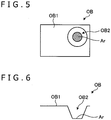
- FIG. 5 is a plan view of the observation target OB as viewed from above.
- FIG. 6 is a side view of the observation target OB.
- FIGS. 4 to 6 illustrate the observation target OB in which a recess OB2 is provided on a part of a surface OB1. Further, in FIGS. 4 and 5 , the deepest area Ar of the recess OB2 is shaded.
- the detection region setting section 264a acquires, via the communication unit 261, an image signal (captured image and depth map information) output from the imaging unit 21 after the image of the observation target OB is captured by the imaging unit 21 from above (step S1).
- the detection region setting section 264a determines the area including the pixel positions whose subject distances have the largest value in the entire image area of the captured image acquired in step S1 on the basis of the depth map information acquired in step S1 (step S2).
- the area including the pixel positions having the largest subject distance is a region corresponding to the deepest area Ar in the observation target OB.
- the detection region setting section 264a sets the area determined in step S2 as the detection region (step S3).
- step S3 the image processing unit 262 executes the detection process on the basis of the pixel information for each pixel of the detection region set in step S2 in the entire image area of the captured image acquired in step S1 (step S4). Then, the image processing unit 262 outputs the detection information obtained by the detection process to the control unit 264.
- step S4 the evaluation value calculating section 264b calculates the evaluation value on the basis of the detection information obtained by the detection process in step S4 (step S5).
- the evaluation value calculating section 264b calculates the focusing evaluation value for evaluating the focusing state of the image in the detection region (area corresponding to the deepest area Ar) set in step S2 in the entire image area of the captured image acquired in step S1 on the basis of the detection information (contrast and frequency component). For example, the evaluation value calculating section 264b uses the contrast obtained by the detection process in step S4 or the sum of the high frequency components among the frequency components obtained by the detection process in step S4 as the focusing evaluation value. Note that the focusing evaluation value indicates a larger value as the subject is more focused on.
- the evaluation value calculating section 264b calculates a brightness evaluation value to change the brightness of the image in the detection region (a region corresponding to the deepest area Ar) set in step S2 in the entire image area of the captured image to the reference brightness (change the detection information (luminance average value) to the reference luminance average value) on the basis of the detection information (luminance average value).
- the evaluation value calculating section 264b calculates the first to fourth brightness evaluation values indicated below as the brightness evaluation values.
- the first brightness evaluation value is the exposure time of each pixel in the image pickup device 215.
- the second brightness evaluation value is the analog gain to be multiplied by the signal processing unit 216.
- the third brightness evaluation value is the digital gain to be multiplied by the image processing unit 262.
- the fourth brightness evaluation value is the amount of illumination light to be supplied by the light source unit 24.
- step S5 the operation control section 264c executes an AF process for adjusting the focal position of the lens unit 211 (step S6).
- step S6 the operation control section 264c executes the AF process for positioning the focus lens 211a at the focal position so that the image in the detection region (the region corresponding to the deepest area Ar) set in step S2 in the entire image area of the captured image acquired in step S1 is in focus, by controlling the movement of the lens drive unit 213a, using a hill climbing method or the like on the basis of the focusing evaluation value calculated in step S5 and the current focal position detected by the focal position detection unit 214a.
- step S6 the operation control section 264c controls the operations of the image pickup device 215, the signal processing unit 216, the image processing unit 262, and the light source unit 24 so as to execute the brightness adjustment process for adjusting the brightness of the image in the detection region (the region corresponding to the deepest area Ar) set in step S2 in the entire image area of the captured image acquired in step S1 to the reference brightness (step S7) .
- the operation control section 264c outputs a control signal to the imaging unit 21 in step S7 and sets the exposure time of each pixel of the image pickup device 215 to the first brightness evaluation value calculated in step S5. Further, the operation control section 264c outputs a control signal to the imaging unit 21 and sets the analog gain to be multiplied by the signal processing unit 216 to the second brightness evaluation value calculated in step S5. Still further, the operation control section 264c outputs a control signal to the image processing unit 262 and sets the digital gain to be multiplied by the image processing unit 262 to the third brightness evaluation value calculated in step S5. In addition, the operation control section 264c outputs a control signal to the light source unit 24, and sets the amount of illumination light supplied by the light source unit 24 to the fourth brightness evaluation value calculated in step S5.
- the deepest area Ar is the region where the surgical operation is performed and is the region that the surgical operator wants to observe most.
- the controller 26 sets a region corresponding to the deepest area Ar in the entire image area of the captured image as the detection region. Then, the controller 26 executes the AF process and the brightness adjustment process on the basis of the detection information obtained by the detection process in the detection region.
- the deepest area Ar (the region that the operator wants to observe most) is automatically focused, and the brightness of the image corresponding to the deepest area Ar (the region that the operator wants to observe most) is automatically adjusted to a desired brightness. Therefore, according to the controller 26 related to the first embodiment, an image suitable for observation can be generated.
- the distance information acquiring unit is integrally mounted on the image pickup device 215 (imaging unit 21).
- the visual field area whose image is captured by the imaging unit 21 can be the same area. That is, the process of matching the depth map acquisition area with the visual field area becomes unnecessary, and the processing load of the controller 26 can be reduced.
- the controller 26 determines the pixel position of a specific subject distance (the pixel position having the largest subject distance) among the pixel positions of the entire image area of the captured image on the basis of the depth map information, but the method is not limited to this. For example, the controller 26 determines the pixel position of a specific subject distance (the pixel position having the largest subject distance) among the pixel positions in the central region including the center of the captured image on the basis of the depth map information. Then, the controller 26 sets the region including the determined pixel position as the detection region and executes the AF process so that the image in the detection region is in focus.
- This modification is made by taking into consideration that the position of the imaging unit 21 is likely to be adjusted so that the position where the operation is performed is located in the central region of the captured image. That is, in the captured image, since the pixel position of a specific subject distance is determined only in the central region, an appropriate pixel position can be extracted while reducing the processing load of the controller 26.
- the operation of the controller 26 is different from that of the first embodiment described above.
- the controller 26 according to the second embodiment executes the pre-operation and the main operation, respectively.
- the pre-operation is an operation to be performed in response to a user operation by the operator on an operation device (not illustrated) such as a mouse, keyboard, or touch panel provided on the controller 26 before performing a surgical operation on the observation target OB, for example.
- an operation device such as a mouse, keyboard, or touch panel provided on the controller 26 before performing a surgical operation on the observation target OB, for example.
- FIG. 7 is a flowchart illustrating the pre-operation of the controller 26 according to the second embodiment.
- FIG. 8 is a diagram illustrating the pre-operation of the controller 26. Specifically, FIG. 8 is a side view of the observation target OB.
- observation target OB illustrated in FIG. 8 is the same observation target as the observation target OB illustrated in FIGS. 4 to 6 .
- the detection region setting section 264a acquires an image signal (captured image and depth map information) output from the imaging unit 21 after image of the observation target OB is captured by the imaging unit 21 from above, via the communication unit 261 (step S8).
- image signal captured image and depth map information
- the captured image only the observation target OB is the subject, and the operator's hand, surgical instrument, or the like is not included.
- the detection region setting section 264a determines the subject distance range to pay attention to (hereinafter referred to as the attention range) on the basis of the depth map information acquired in step S8 (step S9).
- the detection region setting section 264a determines a range RG from the surface OB1 to the deepest area Ar in the observation target OB as the attention range. Then, the detection region setting section 264a stores the attention range determined in step S9 in the storage unit 265.
- the main operation is an operation executed when a surgical operation is performed on the observation target OB, for example.
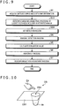
- FIG. 9 is a flowchart illustrating the main operation of the controller 26.
- FIGS. 10 to 12 are diagrams illustrating the main operation of the controller 26.
- FIG. 10 is a perspective view illustrating the observation target OB.
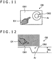
- FIG. 11 is a plan view of the observation target OB as viewed from above.
- FIG. 12 is a side view of the observation target OB.
- observation target OB illustrated in FIGS. 10 to 12 is the same as the observation target OB illustrated in FIGS. 4 to 6 .
- step S10 is adopted instead of step S2 with respect to the operation of the controller 26 ( FIG. 3 ) described in the first embodiment described above, and further, step S3A is adopted instead of step S3, as illustrated in FIG. 9 . Therefore, only steps S10 and S3A will be described in the following.
- Step S10 is executed after step S1.
- step S10 the detection region setting section 264a determines an area including pixel positions of the subject distances included in the attention range in the entire image area of the captured image acquired in step S1, on the basis of the depth map information acquired in step S1 and the attention range stored in the storage unit 265 in step S9.
- step S10 the detection region setting section 264a sets the area determined in step S10 as the detection region (step S3A). After that, the processing proceeds to step S4, and the detection process is executed in the detection region.
- an obstacle EX such as an operator's hand or a surgical instrument enters the space between the imaging unit 21 and the observation target OB, and the obstacle EX is included in the captured image obtained by the imaging unit 21.
- the obstacle EX since the obstacle EX is located outside the range RG corresponding to the attention range (represented by diagonal lines in FIGS. 11 and 12 ), the area other than the area in which the obstacle EX is included in the entire image area of the captured image is set as the detection region.
- the controller 26 determines the attention range in advance by the pre-operation. Further, when the controller 26 executes the main operation, an area having pixel positions of the subject distances included in the attention range in the entire image area of the captured image is set as the detection region. Then, the controller 26 executes the AF process and the brightness adjustment process on the basis of the detection information obtained by the detection process in the detection region.
- the obstacle EX is included in the captured image, the obstacle EX is not focused, and the brightness is not adjusted according to the obstacle EX. Therefore, according to the second embodiment, an image suitable for observation can be generated.
- the operation of the controller 26 is different from that of the first embodiment described above.
- FIG. 13 is a flowchart illustrating the operation of the controller 26 according to the third embodiment.
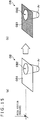
- FIGS. 14 and 15 are diagrams illustrating the operation of the controller 26.
- observation target OB illustrated in FIGS. 14 and 15 is the same as the observation target OB illustrated in FIGS. 4 to 6 .
- step S11 and S12 are adopted instead of step S2, and further step S3B is adopted instead of step S3 with step S6 omitted. Therefore, only steps S11, S12, and S3B will be described below.
- Step S11 is executed after step S1.
- the detection region setting section 264a acquires the current focal position detected by the focal position detection unit 214a via the communication unit 261 in step S11.
- the detection region setting section 264a determines an area currently observed by an operator or the like (hereinafter referred to as an observed area) in the entire image area of the captured image obtained in step S1 on the basis of the depth map information acquired in step S1 and the current focal position acquired in step S11 (step S12).
- step S12 the detection region setting section 264a converts the current focal position acquired in step S11 into the subject distance. Then, the detection region setting section 264a determines the area having the pixel positions of the converted subject distance in the entire image area of the captured image obtained in step S1 as the observed area on the basis of the depth map information acquired in step S1 and the converted subject distance.
- the current focal position is deep and the region observed by the operator or the like is the deepest area Ar.
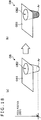
- the area (observed area) having the pixel positions of the subject distance converted from the focal position is determined to be the region corresponding to the deepest area Ar as illustrated by diagonal lines in FIG. 14(b) .
- the region (observed area) having the pixels of the subject distance converted from the focal position is determined to be a region corresponding to the surface OB1 as illustrated by diagonal lines in FIG. 15(b) .
- step S12 the detection region setting section 264a sets the observed area determined in step S12 as the detection region (step S3B). After that, the processing proceeds to step S4, and the detection process is executed in the detection region.
- the step S7 is executed after the step S5 because the step S6 is omitted.
- the controller 26 determines the observed area in the captured image on the basis of the depth map information and the current focal position and sets the observed area as the detection region. Then, the controller 26 executes the brightness adjustment process on the basis of the detection information obtained in the detection process in the detection region.
- an image suitable for observation can be generated according to the third embodiment.
- FIG. 16 illustrates diagrams explaining a modification example of the third embodiment.
- an observation target OB' illustrated in FIG. 16 is different from the observation target OB illustrated in FIGS. 14 and 15 in that the observation target OB' is further provided with a recess OB3 in which the depth position of the deepest area Ar' is the same as that of the area Ar.
- the detection region setting section 264a cannot understand whether to set the region corresponding to the area Ar or the region corresponding to the area Ar' as the detection region in the entire image area of the captured image.
- the detection region in the entire image area of the captured image can be selected according to the user operation by the operator on a mouse, a keyboard, or an operation device (not illustrated) such as a touch panel provided on the controller 26, and a region corresponding to the area Ar is included in the selected detection region (in a case where a region corresponding to the area Ar' is not included in the detection region).
- the detection region setting section 264a sets the region corresponding to the area Ar as the detection region, between the area corresponding to the area Ar and the area corresponding to the area Ar' in the entire image area of the captured image in consideration of the detection region selected by the operator, as illustrated by the diagonal lines in FIG. 16(b) .
- the operation of the controller 26 is different from that of the third embodiment described above.
- FIG. 17 is a flowchart illustrating the operation of the controller 26 according to the fourth embodiment.
- FIG. 18 illustrates diagrams explaining the operation of the controller 26.
- observation target OB illustrated in FIG. 18 is the same observation target as that illustrated in FIGS. 4 to 6 .
- steps S13 and S14 are adopted instead of steps S3B and S4 to S7 in the operation of the controller 26 described in the above third embodiment ( FIG. 13 ). Therefore, only steps S13 and S14 will be described below.
- Step S13 is executed after step S12.
- step S13 the operation control section 264c determines whether or not the subject distance of the observed area determined in step S12 is equal to or greater than a specific threshold value.
- step S13 the result is determined to be "Yes" in step S13.
- step S14 the operation control section 264c adjusts the depth of field (step S14).
- the operation control section 264c increases the aperture value and the depth of field by controlling the operation of the aperture drive unit 213b in step S14.
- the operation control section 264c controls the operation of the image processing unit 262 in step S14 to cause the image processing unit 262 to perform image processing on the captured image acquired in step S1 for increasing the depth of field.
- a known method can be employed for image processing for increasing the depth of field.
- step S13 the operation control section 264c ends the control flow without executing step S14.
- the surgical operator in a case where the surgical operator is performing the operation of the deepest area Ar of the observation target OB, the operator wants to observe regions of other depths, too (for example, the surface OB1).
- the controller 26 determines the observed area in the captured image on the basis of the depth map information and the current focal position, and controls to increase the depth of field in a case where the subject distance of the observed area is equal to or more than a specific threshold value. That is, in a case where the operation of the deepest area Ar is being performed, the captured image is an image in which the surface OB1 is in focus in addition to the deepest area Ar. Accordingly, an image suitable for observation can be generated according to the fourth embodiment.
- the present disclosure is applied to the medical observation system 1 using the surgical operation microscope (medical observation device 2).
- the present disclosure is applied to a medical observation system using a rigid endoscope.
- FIG. 19 is a diagram illustrating a medical observation system 1D according to the fifth embodiment.
- the medical observation system 1D includes a rigid endoscope 2D, a light source unit 24 that is connected to the rigid endoscope 2D via a light guide 25 and that generates the illumination light emitted from the tip of the rigid endoscope 2D, a controller 26 that processes the image signal output from the rigid endoscope 2D, and a display device 3 for displaying a captured image based on the video signal for display processed by the controller 26.
- the rigid endoscope 2D includes an insertion portion 4 and a camera head 21D.
- the insertion portion 4 has an elongated shape and is totally hard, or partially soft with the other part hard, and is inserted into the living organism. Then, the insertion portion 4 takes in light (subject image) from the living organism.
- the camera head 21D is detachably connected to the base end (eyepiece) of the insertion portion 4.
- the camera head 21D has a substantially similar configuration to the imaging unit 21 described in the above-mentioned first embodiment. Then, the camera head 21D captures the subject image taken in by the insertion portion 4 and outputs an image signal.
- the present disclosure is applied to the medical observation system 1 using the surgical operation microscope (medical observation device 2).
- the present disclosure is applied to a medical observation system using a flexible endoscope.
- FIG. 20 is a diagram illustrating a medical observation system 1E according to the sixth embodiment.
- the medical observation system 1E includes a flexible endoscope 2E that captures an in-vivo image of the observation site by inserting an insertion portion 4E into a living organism and outputs an image signal, a light source unit 24 that generates illumination light emitted from the tip of the flexible endoscope 2E, a controller 26 that processes an image signal output from the flexible endoscope 2E, and a display device 3 for displaying a captured image based on a video signal for display processed by the controller 26.
- a flexible endoscope 2E that captures an in-vivo image of the observation site by inserting an insertion portion 4E into a living organism and outputs an image signal
- a light source unit 24 that generates illumination light emitted from the tip of the flexible endoscope 2E
- a controller 26 that processes an image signal output from the flexible endoscope 2E
- a display device 3 for displaying a captured image based on a video signal for display processed by the controller 26.
- the flexible endoscope 2E includes the flexible and elongated insertion portion 4E, an operation unit 5 connected to the base end side of the insertion portion 4E and accepting various operations, and a universal cord 6 extends from the operation unit 5 in a direction different from the extending direction of the insertion portion 4E and containing various cables connected to the light source unit 24 and the controller 26.
- the insertion portion 4E includes a tip 41, a bendable curvature portion 42 connected to the base end side of the tip 41 and having a plurality of bend pieces, and a long flexible tube 43 connected to the base end side of the curvature portion 42 and having flexibility.
- the image signal from the tip 41 is output to the controller 26 via the operation unit 5 and the universal cord 6.
- FIG. 21 is a diagram illustrating a modification example of the first to fourth embodiments.
- the distance information acquiring unit according to the present disclosure integrally includes the image pickup device 215 (imaging unit 21), but the present invention is not limited to this, and the distance information acquiring unit may be separated from the imaging unit 21.
- the visual field area Ar1 whose image is captured by the imaging unit 21 and the depth map acquisition area Ar2 from which the distance information acquiring unit according to the present disclosure acquires depth map information are different. Therefore, as the depth map information, information that limits the depth map acquisition area Ar2 to the visual field area Ar1 is used on the basis of the focal position, the angle of view, and the like in the imaging unit 21.
- the distance information acquiring unit may be configured separately from the imaging unit provided on the camera head 21D and the tip 41 also in the fifth and sixth embodiments.
- the brightness adjustment process includes an adjusting process for only some of the exposure time of each pixel in the image pickup device 215, the analog gain to be multiplied by the signal processing unit 216, the digital gain to be multiplied by the image processing unit 262, and the amount of illumination light supplied by the light source unit 24.
- the first to sixth axes O1 to O6 are respectively configured by passive axes, but the present invention is not limited to this. It is sufficient if at least one of the first to sixth axes O1 to O6 is configured by an active axis that actively rotates the imaging unit 21 around the axis according to the power of the actuator.
Landscapes
- Physics & Mathematics (AREA)
- Engineering & Computer Science (AREA)
- Multimedia (AREA)
- Health & Medical Sciences (AREA)
- Optics & Photonics (AREA)
- General Physics & Mathematics (AREA)
- Life Sciences & Earth Sciences (AREA)
- Signal Processing (AREA)
- Surgery (AREA)
- Chemical & Material Sciences (AREA)
- Analytical Chemistry (AREA)
- General Health & Medical Sciences (AREA)
- Computer Vision & Pattern Recognition (AREA)
- Animal Behavior & Ethology (AREA)
- Molecular Biology (AREA)
- Pathology (AREA)
- Nuclear Medicine, Radiotherapy & Molecular Imaging (AREA)
- Biomedical Technology (AREA)
- Heart & Thoracic Surgery (AREA)
- Medical Informatics (AREA)
- Veterinary Medicine (AREA)
- Public Health (AREA)
- Biophysics (AREA)
- Radiology & Medical Imaging (AREA)
- Oral & Maxillofacial Surgery (AREA)
- Human Computer Interaction (AREA)
- Endoscopes (AREA)
- Studio Devices (AREA)
Applications Claiming Priority (2)
| Application Number | Priority Date | Filing Date | Title |
|---|---|---|---|
| JP2019057334 | 2019-03-25 | ||
| PCT/JP2020/001572 WO2020195042A1 (ja) | 2019-03-25 | 2020-01-17 | 医療用観察システム |
Publications (2)
| Publication Number | Publication Date |
|---|---|
| EP3933480A1 true EP3933480A1 (de) | 2022-01-05 |
| EP3933480A4 EP3933480A4 (de) | 2022-05-11 |
Family
ID=72611729
Family Applications (1)
| Application Number | Title | Priority Date | Filing Date |
|---|---|---|---|
| EP20779512.1A Withdrawn EP3933480A4 (de) | 2019-03-25 | 2020-01-17 | Medizinisches beobachtungssystem |
Country Status (5)
| Country | Link |
|---|---|
| US (1) | US20220155557A1 (de) |
| EP (1) | EP3933480A4 (de) |
| JP (1) | JPWO2020195042A1 (de) |
| CN (1) | CN113574437A (de) |
| WO (1) | WO2020195042A1 (de) |
Cited By (1)
| Publication number | Priority date | Publication date | Assignee | Title |
|---|---|---|---|---|
| WO2023202811A1 (de) * | 2022-04-19 | 2023-10-26 | Schölly Fiberoptic GmbH | Assistiertes autofokus-verfahren und zugehöriges optisches abbildungssystem |
Family Cites Families (9)
| Publication number | Priority date | Publication date | Assignee | Title |
|---|---|---|---|---|
| JP5663331B2 (ja) * | 2011-01-31 | 2015-02-04 | オリンパス株式会社 | 制御装置、内視鏡装置、絞り制御方法及びプログラム |
| US20150237325A1 (en) * | 2012-08-15 | 2015-08-20 | Industrial Technology Research Institute | Method and apparatus for converting 2d images to 3d images |
| JP6357646B2 (ja) * | 2014-03-28 | 2018-07-18 | パナソニックIpマネジメント株式会社 | 撮像装置 |
| JP6505393B2 (ja) | 2014-08-21 | 2019-04-24 | ソニー・オリンパスメディカルソリューションズ株式会社 | 医療用観察装置および医療用観察システム |
| JP6453904B2 (ja) * | 2014-12-02 | 2019-01-16 | オリンパス株式会社 | フォーカス制御装置、内視鏡装置及びフォーカス制御装置の制御方法 |
| JP2015108837A (ja) * | 2015-01-07 | 2015-06-11 | キヤノン株式会社 | 画像処理装置及び画像処理方法 |
| US10992917B2 (en) * | 2016-06-17 | 2021-04-27 | Sony Corporation | Image processing device, image processing method, program, and image processing system that use parallax information |
| US10101572B2 (en) * | 2016-11-23 | 2018-10-16 | Mitutoyo Corporation | Variable focal length lens system with multi-level extended depth of field image processing |
| JP6640378B2 (ja) * | 2016-11-24 | 2020-02-05 | オリンパス株式会社 | 内視鏡装置及び内視鏡装置の制御方法 |
-
2020
- 2020-01-17 US US17/438,949 patent/US20220155557A1/en not_active Abandoned
- 2020-01-17 WO PCT/JP2020/001572 patent/WO2020195042A1/ja not_active Ceased
- 2020-01-17 EP EP20779512.1A patent/EP3933480A4/de not_active Withdrawn
- 2020-01-17 JP JP2021508119A patent/JPWO2020195042A1/ja active Pending
- 2020-01-17 CN CN202080021912.0A patent/CN113574437A/zh active Pending
Cited By (1)
| Publication number | Priority date | Publication date | Assignee | Title |
|---|---|---|---|---|
| WO2023202811A1 (de) * | 2022-04-19 | 2023-10-26 | Schölly Fiberoptic GmbH | Assistiertes autofokus-verfahren und zugehöriges optisches abbildungssystem |
Also Published As
| Publication number | Publication date |
|---|---|
| WO2020195042A1 (ja) | 2020-10-01 |
| CN113574437A (zh) | 2021-10-29 |
| US20220155557A1 (en) | 2022-05-19 |
| JPWO2020195042A1 (de) | 2020-10-01 |
| EP3933480A4 (de) | 2022-05-11 |
Similar Documents
| Publication | Publication Date | Title |
|---|---|---|
| US20240252019A1 (en) | Medical observation system, medical observation apparatus and medical observation method | |
| JP7289653B2 (ja) | 制御装置、内視鏡撮像装置、制御方法、プログラムおよび内視鏡システム | |
| CN110099599B (zh) | 医学图像处理设备、医学图像处理方法和程序 | |
| US20210345856A1 (en) | Medical observation system, medical observation apparatus, and medical observation method | |
| JP7146735B2 (ja) | 制御装置、外部機器、医療用観察システム、制御方法、表示方法およびプログラム | |
| US11483473B2 (en) | Surgical image processing apparatus, image processing method, and surgery system | |
| US20230248231A1 (en) | Medical system, information processing apparatus, and information processing method | |
| US12070182B2 (en) | Signal processing device, imaging device, and signal processing method | |
| US11676242B2 (en) | Image processing apparatus and image processing method | |
| EP3933480A1 (de) | Medizinisches beobachtungssystem | |
| JP2021145859A (ja) | 医療用画像処理装置及び医療用観察システム | |
| US11523065B2 (en) | Imaging device and gain setting method | |
| US12396634B2 (en) | Medical observation device, observation device, observation method, and adapter | |
| EP4205691A1 (de) | Vorrichtung zur verarbeitung medizinischer bilder und system zur medizinischen beobachtung | |
| US10778889B2 (en) | Image pickup apparatus, video signal processing apparatus, and video signal processing method | |
| US20210321082A1 (en) | Information processing apparatus, information processing method, and program | |
| US20200306002A1 (en) | Medical observation control device and medical observation system | |
| US11206355B2 (en) | Image processing apparatus, image processing method, and image processing program | |
| EP2730211B1 (de) | Endoskopvorrichtung | |
| US20210304419A1 (en) | Medical system, information processing apparatus, and information processing method | |
| US20230090615A1 (en) | Medical image processing device and medical observation system |
Legal Events
| Date | Code | Title | Description |
|---|---|---|---|
| STAA | Information on the status of an ep patent application or granted ep patent |
Free format text: STATUS: THE INTERNATIONAL PUBLICATION HAS BEEN MADE |
|
| PUAI | Public reference made under article 153(3) epc to a published international application that has entered the european phase |
Free format text: ORIGINAL CODE: 0009012 |
|
| STAA | Information on the status of an ep patent application or granted ep patent |
Free format text: STATUS: REQUEST FOR EXAMINATION WAS MADE |
|
| 17P | Request for examination filed |
Effective date: 20210909 |
|
| AK | Designated contracting states |
Kind code of ref document: A1 Designated state(s): AL AT BE BG CH CY CZ DE DK EE ES FI FR GB GR HR HU IE IS IT LI LT LU LV MC MK MT NL NO PL PT RO RS SE SI SK SM TR |
|
| A4 | Supplementary search report drawn up and despatched |
Effective date: 20220412 |
|
| RIC1 | Information provided on ipc code assigned before grant |
Ipc: H04N 5/222 20060101ALI20220406BHEP Ipc: H04N 5/238 20060101ALI20220406BHEP Ipc: H04N 17/00 20060101ALI20220406BHEP Ipc: H04N 5/235 20060101ALI20220406BHEP Ipc: H04N 5/232 20060101ALI20220406BHEP Ipc: H04N 5/225 20060101ALI20220406BHEP Ipc: G03B 15/00 20210101ALI20220406BHEP Ipc: G03B 13/36 20210101ALI20220406BHEP Ipc: G03B 7/095 20210101ALI20220406BHEP Ipc: G02B 23/24 20060101ALI20220406BHEP Ipc: G02B 21/36 20060101ALI20220406BHEP Ipc: G02B 7/40 20210101ALI20220406BHEP Ipc: G02B 7/30 20210101ALI20220406BHEP Ipc: G02B 7/28 20210101ALI20220406BHEP Ipc: A61B 1/06 20060101ALI20220406BHEP Ipc: A61B 1/045 20060101ALI20220406BHEP Ipc: A61B 1/00 20060101ALI20220406BHEP Ipc: G02B 21/00 20060101AFI20220406BHEP |
|
| DAV | Request for validation of the european patent (deleted) | ||
| DAX | Request for extension of the european patent (deleted) | ||
| STAA | Information on the status of an ep patent application or granted ep patent |
Free format text: STATUS: EXAMINATION IS IN PROGRESS |
|
| 17Q | First examination report despatched |
Effective date: 20240213 |
|
| STAA | Information on the status of an ep patent application or granted ep patent |
Free format text: STATUS: THE APPLICATION HAS BEEN WITHDRAWN |
|
| 18W | Application withdrawn |
Effective date: 20240412 |