EP3933526A2 - Procédé de surveillance et de commande d'une machine-outil et machine-outil - Google Patents
Procédé de surveillance et de commande d'une machine-outil et machine-outil Download PDFInfo
- Publication number
- EP3933526A2 EP3933526A2 EP21182757.1A EP21182757A EP3933526A2 EP 3933526 A2 EP3933526 A2 EP 3933526A2 EP 21182757 A EP21182757 A EP 21182757A EP 3933526 A2 EP3933526 A2 EP 3933526A2
- Authority
- EP
- European Patent Office
- Prior art keywords
- tool
- machining
- tool carrier
- carrier
- parameter
- Prior art date
- Legal status (The legal status is an assumption and is not a legal conclusion. Google has not performed a legal analysis and makes no representation as to the accuracy of the status listed.)
- Granted
Links
Images


Classifications
-
- G—PHYSICS
- G05—CONTROLLING; REGULATING
- G05B—CONTROL OR REGULATING SYSTEMS IN GENERAL; FUNCTIONAL ELEMENTS OF SUCH SYSTEMS; MONITORING OR TESTING ARRANGEMENTS FOR SUCH SYSTEMS OR ELEMENTS
- G05B19/00—Program-control systems
- G05B19/02—Program-control systems electric
- G05B19/18—Numerical control [NC], i.e. automatically operating machines, in particular machine tools, e.g. in a manufacturing environment, so as to execute positioning, movement or co-ordinated operations by means of program data in numerical form
- G05B19/406—Numerical control [NC], i.e. automatically operating machines, in particular machine tools, e.g. in a manufacturing environment, so as to execute positioning, movement or co-ordinated operations by means of program data in numerical form characterised by monitoring or safety
- G05B19/4065—Monitoring tool breakage, life or condition
-
- G—PHYSICS
- G05—CONTROLLING; REGULATING
- G05B—CONTROL OR REGULATING SYSTEMS IN GENERAL; FUNCTIONAL ELEMENTS OF SUCH SYSTEMS; MONITORING OR TESTING ARRANGEMENTS FOR SUCH SYSTEMS OR ELEMENTS
- G05B2219/00—Program-control systems
- G05B2219/30—Nc systems
- G05B2219/37—Measurements
- G05B2219/37227—Probing tool for its geometry
-
- G—PHYSICS
- G05—CONTROLLING; REGULATING
- G05B—CONTROL OR REGULATING SYSTEMS IN GENERAL; FUNCTIONAL ELEMENTS OF SUCH SYSTEMS; MONITORING OR TESTING ARRANGEMENTS FOR SUCH SYSTEMS OR ELEMENTS
- G05B2219/00—Program-control systems
- G05B2219/30—Nc systems
- G05B2219/37—Measurements
- G05B2219/37234—Monitor tool before, after and during machining
-
- G—PHYSICS
- G05—CONTROLLING; REGULATING
- G05B—CONTROL OR REGULATING SYSTEMS IN GENERAL; FUNCTIONAL ELEMENTS OF SUCH SYSTEMS; MONITORING OR TESTING ARRANGEMENTS FOR SUCH SYSTEMS OR ELEMENTS
- G05B2219/00—Program-control systems
- G05B2219/30—Nc systems
- G05B2219/37—Measurements
- G05B2219/37243—Tool breakage by comparing tool image, length before and after machining
-
- G—PHYSICS
- G05—CONTROLLING; REGULATING
- G05B—CONTROL OR REGULATING SYSTEMS IN GENERAL; FUNCTIONAL ELEMENTS OF SUCH SYSTEMS; MONITORING OR TESTING ARRANGEMENTS FOR SUCH SYSTEMS OR ELEMENTS
- G05B2219/00—Program-control systems
- G05B2219/30—Nc systems
- G05B2219/37—Measurements
- G05B2219/37256—Wear, tool wear
-
- G—PHYSICS
- G05—CONTROLLING; REGULATING
- G05B—CONTROL OR REGULATING SYSTEMS IN GENERAL; FUNCTIONAL ELEMENTS OF SUCH SYSTEMS; MONITORING OR TESTING ARRANGEMENTS FOR SUCH SYSTEMS OR ELEMENTS
- G05B2219/00—Program-control systems
- G05B2219/30—Nc systems
- G05B2219/37—Measurements
- G05B2219/37559—Camera, vision of tool, compute tool center, detect tool wear
-
- G—PHYSICS
- G05—CONTROLLING; REGULATING
- G05B—CONTROL OR REGULATING SYSTEMS IN GENERAL; FUNCTIONAL ELEMENTS OF SUCH SYSTEMS; MONITORING OR TESTING ARRANGEMENTS FOR SUCH SYSTEMS OR ELEMENTS
- G05B2219/00—Program-control systems
- G05B2219/30—Nc systems
- G05B2219/49—Nc machine tool, till multiple
- G05B2219/49304—Tool identification, code
-
- G—PHYSICS
- G05—CONTROLLING; REGULATING
- G05B—CONTROL OR REGULATING SYSTEMS IN GENERAL; FUNCTIONAL ELEMENTS OF SUCH SYSTEMS; MONITORING OR TESTING ARRANGEMENTS FOR SUCH SYSTEMS OR ELEMENTS
- G05B2219/00—Program-control systems
- G05B2219/30—Nc systems
- G05B2219/50—Machine tool, machine tool null till machine tool work handling
- G05B2219/50008—Multiple, multi tool head, parallel machining
-
- G—PHYSICS
- G05—CONTROLLING; REGULATING
- G05B—CONTROL OR REGULATING SYSTEMS IN GENERAL; FUNCTIONAL ELEMENTS OF SUCH SYSTEMS; MONITORING OR TESTING ARRANGEMENTS FOR SUCH SYSTEMS OR ELEMENTS
- G05B2219/00—Program-control systems
- G05B2219/30—Nc systems
- G05B2219/50—Machine tool, machine tool null till machine tool work handling
- G05B2219/50012—Multi slide and indexable multi workpiece spindles
Definitions
- the invention relates to a method for monitoring and controlling a machine tool for machining workpieces and a machine tool for machining workpieces.
- acoustic signals that are generated by a machining tool during a machining process are recorded acoustically by a sensor device and transmitted to an evaluation unit. This evaluates the recorded acoustic signals using appropriate evaluation algorithms in order to identify a tool breakage that is to be expected or that has occurred in the event of a change in the acoustic signals. Since the acoustic signals generated by the machining tool can be influenced by a large number of acoustic disruptive factors, for example further operating noises from the machine tool, incorrect identification of tool breakages can occur.
- the invention is based on the object of proposing a method for monitoring and controlling a machine tool, by means of which a low error rate is achieved when machining workpieces.
- a method for monitoring and controlling a machine tool is defined in claim 1.
- a machine tool for machining workpieces is defined in claim 10. Subclaims relate to specific embodiments.
- the object is achieved by a method for monitoring and controlling a machine tool for processing workpieces, in particular workpieces that are at least partially made of wood, a wood-based material, plastic, composite material or the like, with at least one processing tool for performing a processing operation and with at least one Tool carrier that accommodates the at least one machining tool, solved, with at least one actual state of the at least one machining tool and / or of the at least one tool carrier being optically captured by an image acquisition device and image information of the at least one actual state of a control device being transmitted, from the image information at least one parameter of the at least one machining tool and / or the at least one tool carrier is determined and the control device outputs a control signal as a function of the at least one parameter.
- a reliable method can be achieved for monitoring a control signal and control the machine tool as a function of this parameter.
- the control signal can preferably be a
- the at least one machining tool is monitored and / or a positioning of the machining tool is monitored or controlled.
- the image capturing device can have a camera, by means of which one or more machining tools and / or tool carriers are optically captured.
- the image acquisition device can also have a plurality of cameras, by means of which a plurality of machining tools, for example a plurality of drilling tools of a multi-spindle drill, and / or a plurality of tool carriers are optically recorded.
- the cameras can be arranged at a distance from one another. The multiple cameras can ensure that no machining tool and / or tool carrier is optically covered and that each machining tool and / or each tool carrier is completely optically captured.
- a target state of the at least one machining tool is optically recorded by the image acquisition device and image information of the optically acquired target condition is transmitted to the control device, the The actual state of the at least one machining tool is optically captured by the image capture device at defined time intervals or after a defined number of machining operations, and the actual state and the target state are compared with one another by the control device and a tool defect is identified if a discrepancy is determined between the actual state and the target state and the control signal is output.
- a reference value can be obtained by detecting the target state before executing a machining process and / or after changing at least one machining tool an undamaged machining tool can be determined. By comparing this reference value with the subsequently recorded actual state of the at least one machining tool, a tool defect, for example a tool breakage or tool wear, can be determined. If the actual state is recorded in short time or machining intervals, continuous monitoring of the at least one machining tool can be provided, thereby enabling early detection of a tool defect. In this way, the amount of scrap due to incorrect machining of workpieces can be minimized.
- a further advantageous embodiment of the method can provide that a three-dimensional model of the at least one machining tool and / or of the at least one tool carrier is created by the control device from the image information of the at least one actual state and / or the target state, and the at least one parameter is created from the three-dimensional model the image information is determined.
- the at least one actual state and / or desired state of the at least one machining tool and / or tool carrier can be optically captured by a plurality of cameras or a camera system of the image capturing device. By creating the three-dimensional model, a precise determination of the at least one parameter can be achieved, which enables reliable monitoring and control of the machine tool.
- a further advantageous development of the method can provide that the at least one parameter determined from the image information of the target state and from the image information of the actual state is a tool parameter of the at least one machining tool, in particular a tool shape, a tool length, a tool diameter and / or a comparable tool parameter, being through the control device compares the at least one tool parameter of the actual condition with the at least one tool parameter of the target condition and, if there is a discrepancy between the tool parameter of the actual condition and the tool parameter of the target condition, the tool defect of the at least one machining tool is identified and the control signal is output.
- a tool parameter of the at least one machining tool in particular a tool shape, a tool length, a tool diameter and / or a comparable tool parameter
- the parameter determined from the image information is a tool parameter
- a direct assessment of the tool condition that is to say whether the machining tool is damaged, can be made by comparing the tool parameters. Since only the at least one tool parameter is determined from the image information, an amount of data that has to be processed by the control device for the comparison between the actual state and the target state can also be reduced. Rapid data processing and detection of a tool defect, preferably in real time, can thus be achieved.
- a particularly preferred embodiment of the method can provide that the machine tool has a plurality of machining tools and the image acquisition device for capturing the desired state and for capturing the actual state optically captures the machining tools at the same time, with at least the image information of the nominal state and the image information of the actual state of each machining tool a tool parameter is determined and the at least one tool parameter of the actual state of each machining tool is compared with the at least one tool parameter of the target state and, if there is a discrepancy between the tool parameters, a tool defect of the respective machining tool is identified and the control signal is output.
- a machine tool with such a plurality of machining tools can in particular be a multi-spindle drill.
- a tool with several machining tools can form a drilling gear.
- the machining tools preferably carry out the machining process at the same time. This makes it possible to carry out a machining step in one machining process using each machining tool.
- a corresponding number of drill holes can be made in one or more workpieces at the same time by just one tool stroke.
- the image acquisition device optically acquires an identification device on the at least one tool carrier and transmits identification information to the control device, the control device comparing the identification information and the at least one tool parameter with one another to determine correct tooling and depending on outputs a corresponding control signal for the comparison.
- Drilling gears can be designed, for example, as left-rotating or right-rotating drilling gears.
- the identification device can for example a marking, a barcode, a QR code or the like.
- a further embodiment of the method can provide that an output unit is controlled by the control signal and an error signal is output via the output unit or the machine tool is controlled by the control signal and transferred to an error state or an automated tool change for the relevant machining tool is controlled by the control signal will.
- an operator By outputting the error signal via the output unit, an operator can be informed about the tool defect, so that he can interrupt the machining process at an early stage and replace the defective machining tool.
- the machine tool can also be stopped automatically by the control signal in order not to produce any further faulty workpieces due to a broken or defective machining tool.
- an automated tool change of the relevant machining tool can be activated particularly advantageously, which enables fully automated operation of the machine tool.
- the at least one parameter determined from the image information of the at least one actual state is tool carrier information from the at least one tool carrier, in particular at least one detected tool carrier edge, at least one detected marking on at least one tool carrier and / or at least one comparable tool carrier information, the control device determining a position of the at least one tool carrier as a function of the tool carrier information around the at least one To position the machining tool for the machining process to the workpiece.
- a determination of the position of the tool carrier or the machining tool can be provided by the image acquisition device.
- the image acquisition device By detecting the at least one tool carrier edge, at least one marking and / or at least one comparable tool carrier information item, for example a contour of the workpiece carrier, a distance between the tool carrier and a known position of the image capturing device and based on a known size of an image sensor of the image capturing device can be determined.
- the exact determination of the position of the tool carrier enables the machining tool to be aligned with the workpiece in order to enable precise machining of the workpiece.
- a preferred development of the method can provide that the image information of the at least one actual state is converted into a binary image by the control device and at least one tool carrier edge of the at least one tool carrier, at least one marking on the at least one tool carrier and / or at least one comparable tool carrier information is determined from the binary image and the position of the at least one machining tool is determined by the control device as a function of the detected tool carrier edge, marking and / or comparable tool carrier information.
- the image information By converting the image information into a binary image, reliable identification of the tool carrier information, that is to say the tool carrier edge, tool carrier marking and / or comparable tool carrier information, can be determined from the image information. Because every Pixel is represented by a bit (e.g. value 0 for black; value 1 for white), the data volume of the image information can also be significantly reduced. Rapid data processing, in particular data processing in real time, can thus be made possible.
- the at least one actual state of the at least one tool carrier can be optically captured by at least two spaced-apart cameras of the image capturing device, with the control device generating a stereo-optical from the image information from the one camera and from the image information from the at least one second camera Distance calculation is carried out in order to determine the position of the at least one tool carrier.
- the stereo-optical distance calculation enables a position of the at least one tool carrier or the at least one machining tool to be determined.
- two images, each recorded by one of the two cameras that are spaced apart from one another, are superimposed by the control device.
- the control device can have a corresponding data record of tool carriers or it can detect tool carriers using a self-learning algorithm.
- a further development of the method can also provide that, depending on the determined position of the at least one tool carrier and / or machining tool, an output unit is activated and a position signal is output via the output unit or a positioning device is activated and the at least one tool carrier and / or the at least a machining tool for the machining process is positioned relative to the workpiece to be machined.
- the output of the position signal via the output unit enables an operator to obtain information about the position of the at least one tool carrier or the at least one machining tool.
- a simple position control can be provided and operating errors when positioning the at least one tool carrier can be excluded.
- the tool carrier or the machining tool can be aligned with the workpiece manually or automatically on the basis of the position signal.
- automated positioning can take place by activating the positioning device, whereby fully automated operation of the machine tool can be made possible.
- the task is also achieved by a machine tool for processing workpieces, in particular workpieces that are at least partially made of wood, a wood material, plastic, composite material or the like, with at least one processing tool for performing a processing operation and with a workpiece holder for receiving at least one to be processed Workpiece, solved, wherein an image acquisition device is provided by which a target state and / or actual state of the at least one machining tool and / or of the at least one tool carrier can be optically detected, as well as a Control device by means of which a method according to one of the previously described embodiments can be carried out.
- Such a machine tool can provide simple monitoring and control of a machining process, with both simple and quick identification of damage to the at least one machining tool and monitoring and control of a position of the at least one machining tool.
- the image capturing device can have one or more cameras, by means of which the desired state and / or actual state of the at least one machining tool and / or of the at least one tool carrier can be optically captured. Several cameras can be arranged at a distance from one another. As a result, in addition to a complete recording of each machining tool and / or each tool carrier, the creation of a three-dimensional model of the at least one machining tool and / or of the at least one tool carrier can be provided. This three-dimensional model can be generated from the image information by the control device. The three-dimensional model enables the at least one parameter to be determined precisely.
- Figure 1 shows a perspective view of a machine tool 10 with an image acquisition device 11.
- the machine tool 10 has a plurality of machining tools 12 in order to carry out a machining operation on one or more workpieces (not shown in detail).
- the machine tool 10 is designed as a drilling machine which has a plurality of drilling tools.
- the machining tools 12 form a drilling gear.
- Such a machine tool 10 is also referred to as a multi-spindle drill.
- the machine tool 10 can have a plurality of tool carriers 13, on each of which a plurality of machining tools 12, preferably drilling gears, are arranged.
- the tool carriers 13 can be moved relative to one another by a positioning device 14 in order to position the machining tools 12 for the machining operation on the workpiece.
- a large number of drill holes, in particular rows of holes or hole patterns, can be made in one or more workpieces at the same time - i.e. with only one stroke of the machining tools 12.
- the introduction of such rows of holes or hole patterns is used in particular in the manufacture of furniture parts.
- the processing tools 12 can also be designed as any other processing tools 12, for example as milling tools, sawing tools or the like.
- the machine tool 10 is designed, in particular, as a throughfeed machine in which the machining of the workpieces is provided in a throughfeed process. In order to hold one or more workpieces during the machining process, the machine tool 10 has a workpiece holder 15.
- the machine tool 10 can also be designed as a stationary machine tool.
- the machine tool 10 can also be designed as a CNC-controlled machine tool or form a CNC-controlled machining center.
- the machine tool 10 is provided for machining workpieces which are at least partially made of wood, a wood material, plastic, composite material or the like.
- the workpieces are designed as plate-shaped workpieces, for example as solid wood or chipboard, lightweight panels, sandwich panels or the like. It goes without saying, however, that the machine tool 10 is not limited to the machining of workpieces with such geometries or made of such materials.
- the image capturing device 11 has a plurality of cameras 16 by which the machining tools 12 and / or the tool carriers 13 can be optically captured. According to Figure 1 the image capturing device 11 comprises four cameras 16.
- the image capturing device 11 can likewise be formed by just one camera 16 or by any number of further cameras 16.
- the image capturing device 11 is connected to a control device 17, which transmits the image information optically captured by the cameras 16.
- the cameras 16 can be arranged above the machining tools 12. In addition or as an alternative, cameras 16 can also be provided in a different position on machine tool 10, as exemplified in FIGS Figures 2 to 4 is shown. In particular, the cameras 16 are arranged outside of an immediate processing area of the machine tool 10 in order to avoid soiling of the optics. To avoid soiling or to clean the cameras 16, a compressed air device (not shown in detail) can be assigned to them.
- An actual state of the machining tools 12 and / or the tool carriers 13 can be optically recorded by the image recording device 11.
- This actual state is an image recorded by the camera 16, ie a snapshot of the processing tools 12 and / or the tool carrier 13.
- the image information of the actual state is transmitted to the control device 17 and further processed by it.
- parameters of the machining tools 12 and / or the tool carriers 13 are determined from the image information.
- the image information can be segmented with regard to the recorded processing tools and / or tool carriers.
- the parameters determined enable the machine tool 10 to be monitored and controlled, with a tool defect being able to be identified on the one hand as a function of the parameters, as is shown below with reference to FIG Figures 2 and 3 is described, and on the other hand a positioning of the Processing tools 12 can be controlled, as described below in relation to the Figures 4 and 5 is described.
- the actual state and / or a target state of the machining tools 12 and / or tool carriers 13 can also be optically recorded from different camera angles.
- a three-dimensional model of the machining tools 12 and / or tool carriers 13 can be created by the control device 17 from this image information.
- the parameters of the machining tools 12 and / or the tool carriers 13 can be determined from this three-dimensional model.
- FIG Figure 2 shows a detailed view of the machine tool 10 according to FIG Figure 1 with a camera 16 of the image acquisition device 11.
- This camera 16 is arranged adjacent to the machining tools 12 on the tool carrier 13.
- the processing tools 12 are arranged in a row next to one another on the drilling gear 18.
- the drilling gear 18 is provided with a rotatable receptacle 19 on the tool carrier 13. With such a drilling gear 18 rows of holes can be drilled in workpieces.
- a common recording of the machining tools 12 is provided by the camera 16. This enables the actual state of the machining tools 12 to be recorded quickly and an additional target state of the machining tools 12 to be recorded.
- a tool defect for example a tool breakage of the machining tools 12, can be identified by a comparison between the recorded actual state and the target state, which is explained in more detail below.
- the desired state of the machining tools 12 is recorded before the machining process is carried out. Likewise can it can be provided that the setpoint state of the machining tools 12 is recorded after a new machining tool 12 is replaced, or each time a new machining tool is replaced.
- the setpoint state detected in this way thus serves as a comparison state or reference state of the machining tools 12, with which the actual state for identifying a tool defect is compared by the control device 17.
- the actual state of the processing tools 12 is recorded by the image recording device 11 after a defined number of processing operations or at defined time intervals.
- the control device 17 compares it with the previously detected target state in order to identify a tool defect. By providing short intervals between the detection of the actual condition, a timely identification of a tool defect can be achieved.
- At least one tool parameter is determined from the image information from each machining tool 12.
- This tool parameter is in particular a tool shape, a tool length, a tool diameter, a drill helix pitch and / or a comparable tool parameter.
- the control device 17 compares the at least one tool parameter of the actual state with the at least one tool parameter of the desired state of each machining tool 12. In the event of a discrepancy between the tool parameters due to a damaged, broken or worn machining tool 12, i.e.
- the Control device 17 identifies a tool defect and outputs a corresponding control signal.
- a check of correct loading of the drilling gear 18 with the corresponding machining tool 12 can also be provided.
- adjacent tools 12 can each have opposite directions of rotation.
- the drill helix pitch must be rotated to the left or rotated to the right.
- the drilling gear 18 or the tool carrier 13 can have an identification device, for example a different colored marking, a barcode, QR code or the like.
- the identification device can be captured by the image capture device 11 and the captured identification information can be transmitted to the control device 17.
- the control device 17 compares the detected identification information with the determined tool parameter, in particular with the determined drill helix pitch.
- the control device 17 consequently compares the tool parameter, in particular a left-handed or right-handed drill helix pitch, with the detected identification information and outputs a corresponding control signal when a correct assembly is determined.
- the control signal can control an output unit 21, by means of which an error signal relating to the tool defect is output to an operator of the machine tool 10. It can also be provided that the machine tool 10 is transferred to an error state by the control signal. As a result, in the event of a tool defect, the machining process is automatically interrupted so that no further defective workpieces are manufactured.
- the machine tool 10 can also have a tool changing device, not shown in detail, which can be controlled by the control signal. In this way, after a tool defect has been identified, an automated tool change can be activated and the damaged machining tool 12 can be exchanged.
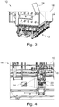
- FIG 3 shows an example of an alternative embodiment of a drilling gear 18, in which the processing tools 12 are arranged in a T-shape to one another.
- the camera 16 of the image capturing device 11 is arranged in such a way that it captures the processing tools 12 together to determine the target state and the actual state.
- a tool defect is identified in the same way as previously with regard to this Figure 2 is described.
- Figure 4 shows a further detailed view of the machine tool 10 according to FIG Figure 1 .
- This shows a camera 16 of the image capturing device 11, which optically captures one of the tool carriers 13 to determine a position of the tool carrier 13.
- the camera 16 is in Figure 4 in a supplementary or in an alternative arrangement to that in Figure 1
- the arrangement shown above the machining area of the machine tool 10 is provided. Provision can be made for a camera 16 to be assigned to each tool carrier 13 in order to record the actual state of the respective tool carrier 13.
- the following statements are made using a tool carrier 13 as an example, but also apply to the further tool carriers 13.
- the camera 16 captures a partial area of the tool carrier 13 and transmits the image information to the control device 17.
- the control device 17 determines as Parameters of the at least one tool carrier 17 are tool carrier information. This is in particular a tool carrier edge 22 or a contour of the tool carrier 13, but can also be a marking on the tool carrier 13 and / or comparable tool carrier information.
- the tool carrier information preferably the tool carrier edge 22, is determined or detected from the image information by the control device 17, in particular by a known method for edge detection.
- a position of the tool carrier 13 is determined by the control device 17 as a function of the detected tool carrier edge 22. Since the position of the camera 16 is known, a relative distance a between the tool carrier 13 and the camera 16 is determined on the basis of the detected tool carrier edge 22 and as a function of a known sensor variable of the camera 16. The absolute position of the tool carrier 13 is determined from this relative distance a between the tool carrier 13 and the camera 16. By determining the absolute position of the tool carrier 13, the machining tool 12 can be aligned manually or automatically for the machining process relative to the workpiece.
- the image information can be converted into a binary image 23 by the control device 17.
- a binary image 23 is exemplified in Figure 5 shown.
- each pixel of the image information is represented by only one bit.
- the value 0 corresponds to black
- the value 1 corresponds to white.
- a black-and-white image is generated in which all the image information that differs from the tool carrier edge 22 is shown in black and only the tool carrier edge 22 is shown in white. This enables reliable detection of the tool carrier edge 22 or also of a tool carrier marking and / or comparable Tool carrier information enables the position of the tool carrier 13 to be determined as a function thereof.
- An alternative determination of the position of the tool carrier 13 can take place by recording the actual state of the tool carrier 13 by two cameras 16 of the image recording device 11 that are spaced apart from one another, as is shown, for example, in FIG Figure 1 is shown.
- the actual state of the tool carrier 13 is recorded by two cameras 16 from two different image angles.
- the tool carrier 13 is optically captured from two different camera angles or camera positions.
- This image information is transmitted to the control device 17, which superimposes the image information from one camera 16 and the image information from the second camera 16. In this way, a stereo image of the tool carrier 13 is created, with a disparity between the image information from the two cameras 16 occurring due to the different image angles.
- the control device 17 uses this image information to carry out a known method for calculating the stereo-optical distance in order to determine the position of the tool carrier 13.
- the control device 17 generates a Distance between the tool carrier 13 and the cameras 16 determined.
- the absolute position of the tool carrier 13 can be determined from this distance.
- the control device 17 can include a data record of tool carriers 13 in order to retrieve them from the captured image information determine.
- the control device 17 can also have a self-learning algorithm for recognizing the tool carriers 13 or the machining tools 12.
- either the output unit 21 can be activated to output the position of the tool carrier 13 or the machining tool 12 to the operator, or the positioning device 14 can be activated to display the tool carrier 13 or the machining tool 12 for to automatically position the machining process for the workpiece to be machined.
Landscapes
- Engineering & Computer Science (AREA)
- Human Computer Interaction (AREA)
- Manufacturing & Machinery (AREA)
- Physics & Mathematics (AREA)
- General Physics & Mathematics (AREA)
- Automation & Control Theory (AREA)
- Machine Tool Sensing Apparatuses (AREA)
- Numerical Control (AREA)
Applications Claiming Priority (1)
| Application Number | Priority Date | Filing Date | Title |
|---|---|---|---|
| DE102020117316.4A DE102020117316A1 (de) | 2020-07-01 | 2020-07-01 | Verfahren zum Überwachen und Steuern einer Werkzeugmaschine und Werkzeugmaschine |
Publications (3)
| Publication Number | Publication Date |
|---|---|
| EP3933526A2 true EP3933526A2 (fr) | 2022-01-05 |
| EP3933526A3 EP3933526A3 (fr) | 2022-03-30 |
| EP3933526B1 EP3933526B1 (fr) | 2024-10-30 |
Family
ID=76730351
Family Applications (1)
| Application Number | Title | Priority Date | Filing Date |
|---|---|---|---|
| EP21182757.1A Active EP3933526B1 (fr) | 2020-07-01 | 2021-06-30 | Procédé de surveillance et de commande d'une machine-outil et machine-outil |
Country Status (2)
| Country | Link |
|---|---|
| EP (1) | EP3933526B1 (fr) |
| DE (1) | DE102020117316A1 (fr) |
Cited By (1)
| Publication number | Priority date | Publication date | Assignee | Title |
|---|---|---|---|---|
| CN115393288A (zh) * | 2022-08-04 | 2022-11-25 | 苏州超集信息科技有限公司 | 加工工艺管控系统及方法 |
Families Citing this family (1)
| Publication number | Priority date | Publication date | Assignee | Title |
|---|---|---|---|---|
| CN115741230B (zh) * | 2022-09-30 | 2024-09-10 | 成都飞机工业(集团)有限责任公司 | 一种在线断刀检测系统及方法 |
Citations (1)
| Publication number | Priority date | Publication date | Assignee | Title |
|---|---|---|---|---|
| DE19726345A1 (de) | 1997-06-21 | 1998-12-24 | Dieter H Ing Grad Gaertner | Akustisches Verfahren zur Vermeidung von Werkzeugbruch |
Family Cites Families (14)
| Publication number | Priority date | Publication date | Assignee | Title |
|---|---|---|---|---|
| DD153746A1 (de) | 1980-10-17 | 1982-01-27 | Lothar Franke | Einrichtung zur kontrolle und ueberwachung an werkzeugmaschinen |
| DE3501533A1 (de) | 1985-01-18 | 1986-07-24 | K.A. Schmersal Gmbh & Co, 5600 Wuppertal | Verfahren und vorrichtung zur werkzeugbruchueberwachung |
| DD239369A1 (de) | 1985-07-16 | 1986-09-24 | Akad Wissenschaften Ddr | Anordnung zur automatischen ueberwachung von ein- und mehrschneidigen werkzeugen an bearbeitungsmaschinen |
| DD272625A1 (de) | 1988-05-31 | 1989-10-18 | Smab Forsch Entw Rat | Verfahren zur automatischen vermessung der werkzeugkonstanten in werkzeugmaschinen |
| DE29902127U1 (de) | 1999-02-09 | 2000-06-29 | Ludwig Demmeler GmbH & Co., 87751 Heimertingen | System zum Wechseln und Einlegen bzw. Vorlegen von Werkzeugen an Werkzeugmaschinen |
| JP2002018680A (ja) * | 2000-07-10 | 2002-01-22 | Mitsubishi Electric Corp | 工作機械 |
| DE102007008698A1 (de) | 2007-02-20 | 2008-08-21 | Deutsche Mechatronics Gmbh | Verfahren zur optischen Voreinrichtung von Stanzmaschinenwerkzeugen und Vorrichtung zur Durchführung |
| DE102012106139B4 (de) | 2012-07-09 | 2015-06-11 | Hochschule Reutlingen | Verfahren und Vorrichtung zur Ermittlung eines Werkzeugverschleißes in einer Werkzeugmaschine zur geometrisch bestimmten Zerspanung |
| DE102014104581B4 (de) | 2014-04-01 | 2023-05-11 | Ks Huayu Alutech Gmbh | Verfahren zur Überwachung eines Werkzeugs, Verfahren zur Qualitätsbeurteilung einer mit dem Werkzeug bearbeiteten Oberfläche eines Werkstücks sowie Vorrichtung zur Durchführung des Verfahrens |
| JP2016093872A (ja) * | 2014-11-14 | 2016-05-26 | 中村留精密工業株式会社 | 工作機械の工具補正値の自動設定装置及び自動設定方法 |
| DE102015105999B4 (de) | 2015-04-20 | 2016-11-10 | Walter Maschinenbau Gmbh | Verfahren und Vorrichtung zur materialabtragenden Bearbeitung eines Werkzeuges |
| DE102017120570A1 (de) | 2017-09-07 | 2019-03-07 | Liebherr-Verzahntechnik Gmbh | Vorrichtung zum Bearbeiten eines Werkstücks mit einem Werkzeug |
| JP6697501B2 (ja) * | 2018-03-26 | 2020-05-20 | ファナック株式会社 | 工作システム |
| JP6679079B1 (ja) * | 2019-08-01 | 2020-04-15 | 株式会社松浦機械製作所 | 工作機械の作動監視システム |
-
2020
- 2020-07-01 DE DE102020117316.4A patent/DE102020117316A1/de active Pending
-
2021
- 2021-06-30 EP EP21182757.1A patent/EP3933526B1/fr active Active
Patent Citations (1)
| Publication number | Priority date | Publication date | Assignee | Title |
|---|---|---|---|---|
| DE19726345A1 (de) | 1997-06-21 | 1998-12-24 | Dieter H Ing Grad Gaertner | Akustisches Verfahren zur Vermeidung von Werkzeugbruch |
Cited By (1)
| Publication number | Priority date | Publication date | Assignee | Title |
|---|---|---|---|---|
| CN115393288A (zh) * | 2022-08-04 | 2022-11-25 | 苏州超集信息科技有限公司 | 加工工艺管控系统及方法 |
Also Published As
| Publication number | Publication date |
|---|---|
| EP3933526B1 (fr) | 2024-10-30 |
| DE102020117316A1 (de) | 2022-01-05 |
| EP3933526A3 (fr) | 2022-03-30 |
Similar Documents
| Publication | Publication Date | Title |
|---|---|---|
| DE69627198T2 (de) | Erzeugung eines messprogramms für nc-bearbeitung und darauf gestütztes bearbeitungsmanagement | |
| EP3427111B1 (fr) | Procédé de fonctionnement d'une machine de chaîne de production ainsi que machine de chaîne de production | |
| DE102018212531B4 (de) | Artikeltransfervorrichtung | |
| DE102009001763A1 (de) | Bearbeitungssimulationsgerät | |
| DE3308764A1 (de) | Verfahren zum steuern der werkzeugauswahl in einer quadriaxial-numerisch gesteuerten drehbank | |
| DE102012106139A1 (de) | Verfahren und Vorrichtung zur Ermittlung eines Werkzeugverschleißes in einer Werkzeugmaschine zur geometrisch bestimmten Zerspanung | |
| EP3867027A1 (fr) | Procédé de visualisation d'informations de processus lors de la production de composants en tôle | |
| DE102008035710A1 (de) | Verfahren zum selbsttätigen Zurückführen eines Werkzeugs einer programmgesteuerten Werkzeugmaschine | |
| EP3933526B1 (fr) | Procédé de surveillance et de commande d'une machine-outil et machine-outil | |
| DE102016003045A1 (de) | Numerische Steuerungsvorrichtung zum Prüfen von Schraubenlöchern | |
| DE102019007387A1 (de) | Datenerstellungsvorrichtung, fehlerbehebungsvorrichtung, datenerstellungsverfahren und datenerstellungsprogramm | |
| EP3403051B1 (fr) | Procédé et dispositif pour définir des données de consigne pour un mesurage d'une pièce à mesurer au moyen d'un appareil de mesure de coordonnées et/ou pour évaluer des résultats de mesure d'un mesurage d'une pièce mesurée au moyen d'un appareil de mesure de coordonnées | |
| WO2019129655A1 (fr) | Procédé d'usinage de pièces et machine-outil | |
| DE102006054275B3 (de) | Verfahren zum Einstellen von jeweils ein spangebendes Werkzeug aufweisenden Bearbeitungseinheiten | |
| DE102014109578A1 (de) | Flügelrad mit einem Blatt, dessen Blattoberfläche aus Linienelementen besteht, und Verfahren zur Bearbeitung des Flügelrads | |
| DE102018114867A1 (de) | Verfahren zum Verbinden von Bauteilen | |
| DE102007048587A1 (de) | Werkzeugmaschinensteuerung | |
| EP3444685A1 (fr) | Cellule d'usinage et procédé d'équipement d'une cellule d'usinage | |
| EP3933512A1 (fr) | Procédé d'usinage soustractif d'une pièce et installation d'usinage | |
| EP4596173A1 (fr) | Procédé avec un appareil de réglage et/ou de mesure d'outil, appareil de réglage d'outil et/ou de mesure d'outil, appareil de serrage d'outil et produit programme informatique | |
| DE10257229A1 (de) | Vorrichtung zur Steuerung einer Werkzeugmaschine sowie Werkzeugmaschinen mit einer solchen Vorrichtung | |
| EP3581935B1 (fr) | Système de détection automatique des objets de travail de laboratoire ainsi que procédé de fonctionnement d'un système de détection automatique des objets de travail de laboratoire | |
| DE102017204629A1 (de) | System mit einem werkzeug und verfahren zum führen eines benutzers eines werkzeugs bei einer behandlung mindestens eines werkstücks | |
| EP3795344B1 (fr) | Ligne de presses et procédé de contrôle de pièces pressées sur cette ligne | |
| WO2019210895A1 (fr) | Détection d'une contrainte d'une pièce usinée sur la base d'une simulation |
Legal Events
| Date | Code | Title | Description |
|---|---|---|---|
| PUAI | Public reference made under article 153(3) epc to a published international application that has entered the european phase |
Free format text: ORIGINAL CODE: 0009012 |
|
| STAA | Information on the status of an ep patent application or granted ep patent |
Free format text: STATUS: THE APPLICATION HAS BEEN PUBLISHED |
|
| AK | Designated contracting states |
Kind code of ref document: A2 Designated state(s): AL AT BE BG CH CY CZ DE DK EE ES FI FR GB GR HR HU IE IS IT LI LT LU LV MC MK MT NL NO PL PT RO RS SE SI SK SM TR |
|
| PUAL | Search report despatched |
Free format text: ORIGINAL CODE: 0009013 |
|
| AK | Designated contracting states |
Kind code of ref document: A3 Designated state(s): AL AT BE BG CH CY CZ DE DK EE ES FI FR GB GR HR HU IE IS IT LI LT LU LV MC MK MT NL NO PL PT RO RS SE SI SK SM TR |
|
| RIC1 | Information provided on ipc code assigned before grant |
Ipc: B23Q 17/24 20060101ALI20220223BHEP Ipc: G05B 19/4065 20060101AFI20220223BHEP |
|
| STAA | Information on the status of an ep patent application or granted ep patent |
Free format text: STATUS: REQUEST FOR EXAMINATION WAS MADE |
|
| 17P | Request for examination filed |
Effective date: 20220830 |
|
| RBV | Designated contracting states (corrected) |
Designated state(s): AL AT BE BG CH CY CZ DE DK EE ES FI FR GB GR HR HU IE IS IT LI LT LU LV MC MK MT NL NO PL PT RO RS SE SI SK SM TR |
|
| STAA | Information on the status of an ep patent application or granted ep patent |
Free format text: STATUS: EXAMINATION IS IN PROGRESS |
|
| 17Q | First examination report despatched |
Effective date: 20230126 |
|
| P01 | Opt-out of the competence of the unified patent court (upc) registered |
Effective date: 20230529 |
|
| GRAP | Despatch of communication of intention to grant a patent |
Free format text: ORIGINAL CODE: EPIDOSNIGR1 |
|
| STAA | Information on the status of an ep patent application or granted ep patent |
Free format text: STATUS: GRANT OF PATENT IS INTENDED |
|
| INTG | Intention to grant announced |
Effective date: 20240606 |
|
| GRAS | Grant fee paid |
Free format text: ORIGINAL CODE: EPIDOSNIGR3 |
|
| GRAA | (expected) grant |
Free format text: ORIGINAL CODE: 0009210 |
|
| STAA | Information on the status of an ep patent application or granted ep patent |
Free format text: STATUS: THE PATENT HAS BEEN GRANTED |
|
| AK | Designated contracting states |
Kind code of ref document: B1 Designated state(s): AL AT BE BG CH CY CZ DE DK EE ES FI FR GB GR HR HU IE IS IT LI LT LU LV MC MK MT NL NO PL PT RO RS SE SI SK SM TR |
|
| REG | Reference to a national code |
Ref country code: GB Ref legal event code: FG4D Free format text: NOT ENGLISH |
|
| REG | Reference to a national code |
Ref country code: CH Ref legal event code: EP |
|
| REG | Reference to a national code |
Ref country code: IE Ref legal event code: FG4D Free format text: LANGUAGE OF EP DOCUMENT: GERMAN |
|
| REG | Reference to a national code |
Ref country code: DE Ref legal event code: R096 Ref document number: 502021005610 Country of ref document: DE |
|
| REG | Reference to a national code |
Ref country code: LT Ref legal event code: MG9D |
|
| REG | Reference to a national code |
Ref country code: NL Ref legal event code: MP Effective date: 20241030 |
|
| PG25 | Lapsed in a contracting state [announced via postgrant information from national office to epo] |
Ref country code: IS Free format text: LAPSE BECAUSE OF FAILURE TO SUBMIT A TRANSLATION OF THE DESCRIPTION OR TO PAY THE FEE WITHIN THE PRESCRIBED TIME-LIMIT Effective date: 20250228 Ref country code: PT Free format text: LAPSE BECAUSE OF FAILURE TO SUBMIT A TRANSLATION OF THE DESCRIPTION OR TO PAY THE FEE WITHIN THE PRESCRIBED TIME-LIMIT Effective date: 20250228 Ref country code: HR Free format text: LAPSE BECAUSE OF FAILURE TO SUBMIT A TRANSLATION OF THE DESCRIPTION OR TO PAY THE FEE WITHIN THE PRESCRIBED TIME-LIMIT Effective date: 20241030 |
|
| PG25 | Lapsed in a contracting state [announced via postgrant information from national office to epo] |
Ref country code: NL Free format text: LAPSE BECAUSE OF FAILURE TO SUBMIT A TRANSLATION OF THE DESCRIPTION OR TO PAY THE FEE WITHIN THE PRESCRIBED TIME-LIMIT Effective date: 20241030 Ref country code: FI Free format text: LAPSE BECAUSE OF FAILURE TO SUBMIT A TRANSLATION OF THE DESCRIPTION OR TO PAY THE FEE WITHIN THE PRESCRIBED TIME-LIMIT Effective date: 20241030 |
|
| PG25 | Lapsed in a contracting state [announced via postgrant information from national office to epo] |
Ref country code: BG Free format text: LAPSE BECAUSE OF FAILURE TO SUBMIT A TRANSLATION OF THE DESCRIPTION OR TO PAY THE FEE WITHIN THE PRESCRIBED TIME-LIMIT Effective date: 20241030 |
|
| PG25 | Lapsed in a contracting state [announced via postgrant information from national office to epo] |
Ref country code: ES Free format text: LAPSE BECAUSE OF FAILURE TO SUBMIT A TRANSLATION OF THE DESCRIPTION OR TO PAY THE FEE WITHIN THE PRESCRIBED TIME-LIMIT Effective date: 20241030 |
|
| PG25 | Lapsed in a contracting state [announced via postgrant information from national office to epo] |
Ref country code: NO Free format text: LAPSE BECAUSE OF FAILURE TO SUBMIT A TRANSLATION OF THE DESCRIPTION OR TO PAY THE FEE WITHIN THE PRESCRIBED TIME-LIMIT Effective date: 20250130 |
|
| PG25 | Lapsed in a contracting state [announced via postgrant information from national office to epo] |
Ref country code: GR Free format text: LAPSE BECAUSE OF FAILURE TO SUBMIT A TRANSLATION OF THE DESCRIPTION OR TO PAY THE FEE WITHIN THE PRESCRIBED TIME-LIMIT Effective date: 20250131 Ref country code: LV Free format text: LAPSE BECAUSE OF FAILURE TO SUBMIT A TRANSLATION OF THE DESCRIPTION OR TO PAY THE FEE WITHIN THE PRESCRIBED TIME-LIMIT Effective date: 20241030 |
|
| PG25 | Lapsed in a contracting state [announced via postgrant information from national office to epo] |
Ref country code: PL Free format text: LAPSE BECAUSE OF FAILURE TO SUBMIT A TRANSLATION OF THE DESCRIPTION OR TO PAY THE FEE WITHIN THE PRESCRIBED TIME-LIMIT Effective date: 20241030 |
|
| PG25 | Lapsed in a contracting state [announced via postgrant information from national office to epo] |
Ref country code: RS Free format text: LAPSE BECAUSE OF FAILURE TO SUBMIT A TRANSLATION OF THE DESCRIPTION OR TO PAY THE FEE WITHIN THE PRESCRIBED TIME-LIMIT Effective date: 20250130 |
|
| PG25 | Lapsed in a contracting state [announced via postgrant information from national office to epo] |
Ref country code: SM Free format text: LAPSE BECAUSE OF FAILURE TO SUBMIT A TRANSLATION OF THE DESCRIPTION OR TO PAY THE FEE WITHIN THE PRESCRIBED TIME-LIMIT Effective date: 20241030 |
|
| PGFP | Annual fee paid to national office [announced via postgrant information from national office to epo] |
Ref country code: DE Payment date: 20250624 Year of fee payment: 5 |
|
| PG25 | Lapsed in a contracting state [announced via postgrant information from national office to epo] |
Ref country code: DK Free format text: LAPSE BECAUSE OF FAILURE TO SUBMIT A TRANSLATION OF THE DESCRIPTION OR TO PAY THE FEE WITHIN THE PRESCRIBED TIME-LIMIT Effective date: 20241030 |
|
| PGFP | Annual fee paid to national office [announced via postgrant information from national office to epo] |
Ref country code: IT Payment date: 20250530 Year of fee payment: 5 |
|
| PG25 | Lapsed in a contracting state [announced via postgrant information from national office to epo] |
Ref country code: EE Free format text: LAPSE BECAUSE OF FAILURE TO SUBMIT A TRANSLATION OF THE DESCRIPTION OR TO PAY THE FEE WITHIN THE PRESCRIBED TIME-LIMIT Effective date: 20241030 |
|
| PG25 | Lapsed in a contracting state [announced via postgrant information from national office to epo] |
Ref country code: RO Free format text: LAPSE BECAUSE OF FAILURE TO SUBMIT A TRANSLATION OF THE DESCRIPTION OR TO PAY THE FEE WITHIN THE PRESCRIBED TIME-LIMIT Effective date: 20241030 |
|
| PG25 | Lapsed in a contracting state [announced via postgrant information from national office to epo] |
Ref country code: SK Free format text: LAPSE BECAUSE OF FAILURE TO SUBMIT A TRANSLATION OF THE DESCRIPTION OR TO PAY THE FEE WITHIN THE PRESCRIBED TIME-LIMIT Effective date: 20241030 |
|
| PG25 | Lapsed in a contracting state [announced via postgrant information from national office to epo] |
Ref country code: CZ Free format text: LAPSE BECAUSE OF FAILURE TO SUBMIT A TRANSLATION OF THE DESCRIPTION OR TO PAY THE FEE WITHIN THE PRESCRIBED TIME-LIMIT Effective date: 20241030 |
|
| REG | Reference to a national code |
Ref country code: DE Ref legal event code: R097 Ref document number: 502021005610 Country of ref document: DE |
|
| PLBE | No opposition filed within time limit |
Free format text: ORIGINAL CODE: 0009261 |
|
| STAA | Information on the status of an ep patent application or granted ep patent |
Free format text: STATUS: NO OPPOSITION FILED WITHIN TIME LIMIT |
|
| PG25 | Lapsed in a contracting state [announced via postgrant information from national office to epo] |
Ref country code: SE Free format text: LAPSE BECAUSE OF FAILURE TO SUBMIT A TRANSLATION OF THE DESCRIPTION OR TO PAY THE FEE WITHIN THE PRESCRIBED TIME-LIMIT Effective date: 20241030 |
|
| 26N | No opposition filed |
Effective date: 20250731 |
|
| REG | Reference to a national code |
Ref country code: CH Ref legal event code: H13 Free format text: ST27 STATUS EVENT CODE: U-0-0-H10-H13 (AS PROVIDED BY THE NATIONAL OFFICE) Effective date: 20260127 |
|
| PG25 | Lapsed in a contracting state [announced via postgrant information from national office to epo] |
Ref country code: MC Free format text: LAPSE BECAUSE OF FAILURE TO SUBMIT A TRANSLATION OF THE DESCRIPTION OR TO PAY THE FEE WITHIN THE PRESCRIBED TIME-LIMIT Effective date: 20241030 |
|
| PG25 | Lapsed in a contracting state [announced via postgrant information from national office to epo] |
Ref country code: LU Free format text: LAPSE BECAUSE OF NON-PAYMENT OF DUE FEES Effective date: 20250630 |
|
| GBPC | Gb: european patent ceased through non-payment of renewal fee |
Effective date: 20250630 |
|
| REG | Reference to a national code |
Ref country code: BE Ref legal event code: MM Effective date: 20250630 |
|
| PG25 | Lapsed in a contracting state [announced via postgrant information from national office to epo] |
Ref country code: GB Free format text: LAPSE BECAUSE OF NON-PAYMENT OF DUE FEES Effective date: 20250630 |
|
| PG25 | Lapsed in a contracting state [announced via postgrant information from national office to epo] |
Ref country code: IE Free format text: LAPSE BECAUSE OF NON-PAYMENT OF DUE FEES Effective date: 20250630 |
|
| PGFP | Annual fee paid to national office [announced via postgrant information from national office to epo] |
Ref country code: AT Payment date: 20260410 Year of fee payment: 5 |
|
| PG25 | Lapsed in a contracting state [announced via postgrant information from national office to epo] |
Ref country code: BE Free format text: LAPSE BECAUSE OF NON-PAYMENT OF DUE FEES Effective date: 20250630 |
|
| PG25 | Lapsed in a contracting state [announced via postgrant information from national office to epo] |
Ref country code: FR Free format text: LAPSE BECAUSE OF NON-PAYMENT OF DUE FEES Effective date: 20250630 |
|
| PG25 | Lapsed in a contracting state [announced via postgrant information from national office to epo] |
Ref country code: CH Free format text: LAPSE BECAUSE OF NON-PAYMENT OF DUE FEES Effective date: 20250630 |