EP3933801A2 - Procédé, appareil et dispositif de test de système de surveillance de flux de trafic - Google Patents
Procédé, appareil et dispositif de test de système de surveillance de flux de trafic Download PDFInfo
- Publication number
- EP3933801A2 EP3933801A2 EP21193479.9A EP21193479A EP3933801A2 EP 3933801 A2 EP3933801 A2 EP 3933801A2 EP 21193479 A EP21193479 A EP 21193479A EP 3933801 A2 EP3933801 A2 EP 3933801A2
- Authority
- EP
- European Patent Office
- Prior art keywords
- traffic flow
- monitoring system
- flow monitoring
- obstacle data
- real
- Prior art date
- Legal status (The legal status is an assumption and is not a legal conclusion. Google has not performed a legal analysis and makes no representation as to the accuracy of the status listed.)
- Granted
Links
Images




Classifications
-
- G—PHYSICS
- G06—COMPUTING OR CALCULATING; COUNTING
- G06F—ELECTRIC DIGITAL DATA PROCESSING
- G06F11/00—Error detection; Error correction; Monitoring
- G06F11/36—Prevention of errors by analysis, debugging or testing of software
- G06F11/3668—Testing of software
- G06F11/3672—Test management
- G06F11/3688—Test management for test execution, e.g. scheduling of test suites
-
- G—PHYSICS
- G08—SIGNALLING
- G08G—TRAFFIC CONTROL SYSTEMS
- G08G1/00—Traffic control systems for road vehicles
- G08G1/01—Detecting movement of traffic to be counted or controlled
- G08G1/0104—Measuring and analyzing of parameters relative to traffic conditions
- G08G1/0125—Traffic data processing
- G08G1/0129—Traffic data processing for creating historical data or processing based on historical data
-
- G—PHYSICS
- G06—COMPUTING OR CALCULATING; COUNTING
- G06F—ELECTRIC DIGITAL DATA PROCESSING
- G06F11/00—Error detection; Error correction; Monitoring
- G06F11/36—Prevention of errors by analysis, debugging or testing of software
- G06F11/3668—Testing of software
- G06F11/3696—Methods or tools to render software testable
-
- G—PHYSICS
- G06—COMPUTING OR CALCULATING; COUNTING
- G06F—ELECTRIC DIGITAL DATA PROCESSING
- G06F11/00—Error detection; Error correction; Monitoring
- G06F11/36—Prevention of errors by analysis, debugging or testing of software
- G06F11/3698—Environments for analysis, debugging or testing of software
-
- G—PHYSICS
- G06—COMPUTING OR CALCULATING; COUNTING
- G06Q—INFORMATION AND COMMUNICATION TECHNOLOGY [ICT] SPECIALLY ADAPTED FOR ADMINISTRATIVE, COMMERCIAL, FINANCIAL, MANAGERIAL OR SUPERVISORY PURPOSES; SYSTEMS OR METHODS SPECIALLY ADAPTED FOR ADMINISTRATIVE, COMMERCIAL, FINANCIAL, MANAGERIAL OR SUPERVISORY PURPOSES, NOT OTHERWISE PROVIDED FOR
- G06Q50/00—Information and communication technology [ICT] specially adapted for implementation of business processes of specific business sectors, e.g. utilities or tourism
- G06Q50/10—Services
-
- G—PHYSICS
- G06—COMPUTING OR CALCULATING; COUNTING
- G06Q—INFORMATION AND COMMUNICATION TECHNOLOGY [ICT] SPECIALLY ADAPTED FOR ADMINISTRATIVE, COMMERCIAL, FINANCIAL, MANAGERIAL OR SUPERVISORY PURPOSES; SYSTEMS OR METHODS SPECIALLY ADAPTED FOR ADMINISTRATIVE, COMMERCIAL, FINANCIAL, MANAGERIAL OR SUPERVISORY PURPOSES, NOT OTHERWISE PROVIDED FOR
- G06Q50/00—Information and communication technology [ICT] specially adapted for implementation of business processes of specific business sectors, e.g. utilities or tourism
- G06Q50/40—Business processes related to the transportation industry
-
- G—PHYSICS
- G06—COMPUTING OR CALCULATING; COUNTING
- G06V—IMAGE OR VIDEO RECOGNITION OR UNDERSTANDING
- G06V20/00—Scenes; Scene-specific elements
- G06V20/50—Context or environment of the image
- G06V20/52—Surveillance or monitoring of activities, e.g. for recognising suspicious objects
- G06V20/54—Surveillance or monitoring of activities, e.g. for recognising suspicious objects of traffic, e.g. cars on the road, trains or boats
-
- G—PHYSICS
- G06—COMPUTING OR CALCULATING; COUNTING
- G06V—IMAGE OR VIDEO RECOGNITION OR UNDERSTANDING
- G06V20/00—Scenes; Scene-specific elements
- G06V20/50—Context or environment of the image
- G06V20/56—Context or environment of the image exterior to a vehicle by using sensors mounted on the vehicle
- G06V20/58—Recognition of moving objects or obstacles, e.g. vehicles or pedestrians; Recognition of traffic objects, e.g. traffic signs, traffic lights or roads
-
- G—PHYSICS
- G08—SIGNALLING
- G08G—TRAFFIC CONTROL SYSTEMS
- G08G1/00—Traffic control systems for road vehicles
- G08G1/01—Detecting movement of traffic to be counted or controlled
- G08G1/0104—Measuring and analyzing of parameters relative to traffic conditions
- G08G1/0108—Measuring and analyzing of parameters relative to traffic conditions based on the source of data
- G08G1/0112—Measuring and analyzing of parameters relative to traffic conditions based on the source of data from the vehicle, e.g. floating car data [FCD]
-
- G—PHYSICS
- G08—SIGNALLING
- G08G—TRAFFIC CONTROL SYSTEMS
- G08G1/00—Traffic control systems for road vehicles
- G08G1/01—Detecting movement of traffic to be counted or controlled
- G08G1/0104—Measuring and analyzing of parameters relative to traffic conditions
- G08G1/0108—Measuring and analyzing of parameters relative to traffic conditions based on the source of data
- G08G1/0116—Measuring and analyzing of parameters relative to traffic conditions based on the source of data from roadside infrastructure, e.g. beacons
-
- G—PHYSICS
- G08—SIGNALLING
- G08G—TRAFFIC CONTROL SYSTEMS
- G08G1/00—Traffic control systems for road vehicles
- G08G1/01—Detecting movement of traffic to be counted or controlled
- G08G1/0104—Measuring and analyzing of parameters relative to traffic conditions
- G08G1/0108—Measuring and analyzing of parameters relative to traffic conditions based on the source of data
- G08G1/012—Measuring and analyzing of parameters relative to traffic conditions based on the source of data from other sources than vehicle or roadside beacons, e.g. mobile networks
-
- G—PHYSICS
- G06—COMPUTING OR CALCULATING; COUNTING
- G06F—ELECTRIC DIGITAL DATA PROCESSING
- G06F30/00—Computer-aided design [CAD]
- G06F30/10—Geometric CAD
- G06F30/15—Vehicle, aircraft or watercraft design
-
- G—PHYSICS
- G06—COMPUTING OR CALCULATING; COUNTING
- G06F—ELECTRIC DIGITAL DATA PROCESSING
- G06F30/00—Computer-aided design [CAD]
- G06F30/20—Design optimisation, verification or simulation
-
- G—PHYSICS
- G08—SIGNALLING
- G08G—TRAFFIC CONTROL SYSTEMS
- G08G1/00—Traffic control systems for road vehicles
- G08G1/01—Detecting movement of traffic to be counted or controlled
- G08G1/0104—Measuring and analyzing of parameters relative to traffic conditions
- G08G1/0137—Measuring and analyzing of parameters relative to traffic conditions for specific applications
- G08G1/0145—Measuring and analyzing of parameters relative to traffic conditions for specific applications for active traffic flow control
Definitions
- the present application relates to intelligent traffic, vehicle-road collaboration, and cloud platform technologies in a field of data processing and, in particular, to a method, an apparatus and a device for testing a traffic flow monitoring system.
- an on board device and a roadside device collect obstacle data on a road, and report the obstacle data to a traffic flow monitoring system.
- the traffic flow monitoring system perceives and processes the obstacle data, so as to realize a monitoring of a traffic flow.
- the traffic flow monitoring system needs to be tested before it goes online.
- the simulated obstacle constructed by the mock tool is a static obstacle, which cannot a simulate movement characteristic of an obstacle in a real traffic scene, so that the accuracy of the test result for the traffic flow monitoring system cannot be guaranteed.
- the present disclosure provide a method, an apparatus and a device for testing a traffic flow monitoring system.
- a method for testing a traffic flow monitoring system including:
- an apparatus for testing a traffic flow monitoring system including:
- an electronic device including:
- a non-transitory computer readable storage medium stored with computer instructions, where the computer instructions are configured to enable a computer to execute the method described in any one of the first aspect.
- a computer program product includes a computer program
- the computer program is stored in a readable storage medium
- at least one processor of an electronic device can read the computer program from the readable storage medium
- the at least one processor executes the computer program to enable the electronic device to execute the method described in any one of the first aspect.
- the present application provides a method, an apparatus and a device for test a traffic flow monitoring system, which are applied to intelligent traffic, vehicle-road collaboration, and cloud platform technologies in a field of data processing, to improve an accuracy of a test result for the traffic flow monitoring system.
- a vehicle-road collaboration system is a development direction of the Intelligent Traffic System (ITS).
- ITS Intelligent Traffic System
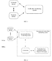
- FIG. 1 is a schematic diagram of a traffic flow monitoring scene provided by an embodiment of the present application.
- the application scene includes: an on board device, a roadside device, and a traffic flow monitoring system.
- the traffic flow monitoring system may be a server located in a cloud, a cloud platform, a vehicle-road system management platform, a central subsystem, etc.
- the on board device may be connected to the roadside device, the roadside device may be connected to the traffic flow monitoring system, and the on board device may also be directly connected to the traffic flow monitoring system.
- the roadside device may include a roadside sensing device and a roadside computing device, where the roadside sensing device is connected to the roadside computing device, and the roadside computing device is connected to the traffic flow monitoring system.
- the roadside sensing device itself includes computing functions, and the roadside sensing device may be directly connected to the traffic flow monitoring system. The above connection may be wired or wireless.
- the on board device may include an on board terminal, on board units (OBU), and so on.
- the roadside device may include a camera, a webcam, a road side unit (RSU), a roadside computing unit, and so on.
- the on board device and roadside device may collect an obstacle in the current traffic scene to obtain obstacle data.
- the obstacles include but is not limited to: a pedestrian, a vehicle, a bicycle, a motorcycle, and so on in the traffic scene.
- the on board device and the roadside device report the collected obstacle data to the traffic flow monitoring system.
- the traffic flow monitoring system determines the state of the traffic flow by comprehensively perceiving and analyzing the obstacle data reported by the on board device and/or roadside device.
- the traffic flow monitoring system needs to be tested before it goes online, and it may be tested offline. Since an offline traffic flow monitoring system does not have real data sources (that is, it is cannot to obtain obstacle data collected by the on-board device and the roadside device), therefore, some implementations need to use a mock tool to construct simulated obstacle data and input the simulated obstacle data into the traffic flow monitoring system to test the traffic flow monitoring system.
- the simulated obstacle constructed by the mock tool is a static obstacle, which cannot simulate the movement characteristic of an obstacle in a real traffic scene, so that the accuracy of the test result for the traffic flow monitoring system cannot be guaranteed.
- a dynamic obstacle in the case of using the mock tool to construct the static obstacle, can be constructed by adding random movement to the static obstacle.
- the obstacle constructed in this way is in a movement state, the movement of the obstacle is random, and it is difficult to form a driving trajectory of an obstacle in a real traffic scene. That is to say, the obstacle constructed in this way still cannot simulate the movement characteristic of the obstacle in the real traffic scene, and thus the accuracy of the test result for the traffic flow monitoring system cannot be guaranteed.
- an embodiment of the present application provides a method for testing a traffic flow monitoring system.
- the following describes the test scene of the traffic flow monitoring system in an embodiment of the present application with reference to FIG. 2 .
- FIG. 2 is a schematic diagram of a test scene of a traffic flow monitoring system provided by an embodiment of the present application.
- the test scene includes a first traffic flow monitoring system and a test device.
- the first traffic flow monitoring system is an object to be tested, and the test device is used to test the first traffic flow monitoring system.
- the test device may send simulated obstacle data to the first traffic flow monitoring system.
- the test device may also obtain a monitoring result from the first traffic flow monitoring system, so as to determine a test result according to the monitoring result.
- the test device may be any electronic device with data processing and data sending/receiving function, including but not limited to a desktop computer, a notebook computer, a tablet computer, a personal computer, etc.
- the test device may obtain real obstacle data collected in a real traffic scene, and generate simulated obstacle data according to the real obstacle data, where the simulated obstacle data is used to simulate an obstacle in the real traffic scene and a movement state thereof, and then send the simulated obstacle data to the first traffic flow monitoring system to test the first traffic flow monitoring system.
- the test scene may also include a second traffic flow monitoring system.
- the second traffic flow monitoring system may be an online traffic flow monitoring system.
- the second traffic flow monitoring system may obtain the real obstacle data from an on board device, a roadside device, etc. In this way, the test device can establish a communication connection with the second traffic flow monitoring system, and obtain the real obstacle data from the second traffic flow monitoring system.
- the simulated obstacle data is generated according to the real obstacle data collected in the real traffic scene, and the simulated obstacle data simulates the obstacle in the real traffic scene and the movement state thereof, therefore, using the simulated obstacle data to test the first traffic flow monitoring system can ensure the authenticity of the obstacle and the movement state thereof input into the first traffic flow monitoring system, thereby ensuring the accuracy of the test result for the first traffic flow monitoring system.
- FIG. 3 is a schematic flowchart of a method for testing a traffic flow monitoring system provided by an embodiment of the present application.
- the method of this embodiment may be used to test the first traffic flow monitoring system, that is, the object to be tested in the method of this embodiment is the first traffic flow monitoring system.
- the method of the present embodiment includes: S301: obtaining real obstacle data collected in a real traffic scene.
- the executive body of this embodiment may be the test device in FIG. 2 .
- the test device is in communication connection with the first traffic flow monitoring system for testing the first traffic flow monitoring system.
- the real obstacle data includes data related to each obstacle in the real traffic scene.
- the obstacle in the embodiment of the present application may be a traffic participant, such as a vehicle, a pedestrian, a bicycle, a motorcycle, and so on.
- the real obstacle data may be collected by the on board device and/or the roadside device in the real traffic scene.
- the form of the real obstacle data can include but is not limited to image data, video data, radar data, infrared data, point cloud data, etc., and can also be result data obtained by calculating and analyzing one or more of the above data.
- the real obstacle data may be obtained from the online second traffic flow monitoring system.
- the test device establishes a communication connection with the second traffic flow monitoring system, and the test device may monitor the real obstacle data input to the second traffic flow monitoring system to obtain the real obstacle data.
- the real obstacle data may also be obtained from a database.
- the database is used to store historical obstacle data collected by an on board device and/or a roadside device in each road section/area.
- the test device may obtain the historical obstacle data from the database according to a test requirement. These historical obstacle data are the real obstacle data.
- the test device determines a traffic flow type of a scene to be tested corresponding to the first traffic flow monitoring system according to an actual test requirement.
- the traffic flow type may be any one of the following: a large flow scene, a medium flow scene, a low flow scene, a morning peak scene, an evening peak scene, a congested scene, an unblocked scenes, etc.
- the real obstacle data corresponding to the real traffic scene that is consistent with the traffic flow type of the scene to be tested, it can meet the requirements of multiple test scenes and ensure the accuracy of the test results for different test scenes.
- S302 generating simulated obstacle data according to the real obstacle data, where the simulated obstacle data is used to simulate an obstacle in the real traffic scene and a movement state of the obstacle.
- the simulated obstacle data may be obtained by modifying the real obstacle data.
- the real obstacle data is modified, the related information about the obstacle in the real obstacle data and the movement state thereof can be retained, so that the generated simulated obstacle data can simulate the obstacle in the real traffic scene and the movement state of the obstacle.
- the real obstacle data can be modified according to an interface rule of the first traffic flow monitoring system to obtain the simulated obstacle data.
- the interface rule of the first traffic flow monitoring system refers to a condition that the obstacle data input into the first traffic flow monitoring system need to meet.
- the interface rule is used to indicate an interface parameter and an interface data format of the first traffic flow monitoring system.
- the real obstacle data is modified according to the interface rule of the first traffic flow monitoring system, so that the simulated obstacle data obtained after the modifying meets the interface rule of the first traffic flow monitoring system, thereby making the first traffic flow monitoring system can identify and analyze the simulated obstacle data.
- S303 sending the simulated obstacle data to a first traffic flow monitoring system to be tested to test the first traffic flow monitoring system.
- the simulated obstacle data is sent to the first traffic flow monitoring system to trigger the first traffic flow monitoring system to perform a perception analysis on the simulated obstacle data, thereby realizing the test of the first traffic flow monitoring system.
- the simulated obstacle data is sent to the first traffic flow monitoring system
- multiple aspects of the first traffic flow monitoring system can be tested, including but not limited to: a link connectivity test, a performance stability test, an accuracy test of the monitoring result, etc., which is not limited in this embodiment.
- the method for testing a traffic flow monitoring system includes: obtaining real obstacle data collected in a real traffic scene; generating simulated obstacle data according to the real obstacle data, where the simulated obstacle data is used to simulate an obstacle in the real traffic scene and a movement state of the obstacle; and sending the simulated obstacle data to a first traffic flow monitoring system to be tested to test the first traffic flow monitoring system.
- testing the first traffic flow monitoring system using the simulated obstacle data can ensure an authenticity of the obstacle and the movement state thereof input into the first traffic flow monitoring system, thereby ensuring the accuracy of the test result for the first traffic flow monitoring system.
- FIG. 4 is a schematic flowchart of generating simulated obstacle data based on real obstacle data according to an embodiment of the present application. As shown in FIG. 4 , the method of this embodiment includes: S401: analyzing the real obstacle data according to a data format corresponding to the real obstacle data to obtain an analysis result.
- the real obstacle data may be obtained from the second traffic flow monitoring system, and a data format adopted by the second traffic flow monitoring system may not satisfies the interface rule of the first traffic flow monitoring system. Therefore, it is necessary to analyze the real obstacle data according to the data format corresponding to the real obstacle data firstly to obtain the analysis result, and then modify the analysis result according to the interface rule of the first traffic flow monitoring system to obtain the simulated obstacle data.
- the test device parses the real obstacle data according to the PB data structure to obtain the analysis result.
- PB protocol buffer
- S402 extracting the value of the interface parameter from the analysis result according to the interface parameter of the first traffic flow monitoring system.
- the interface parameter indicate a parameter required by the input of the first traffic flow monitoring system, including but not limited to a parameter used to describe the obstacle and the movement state thereof.
- the interface parameter includes but is not limited to: an identification of the obstacle, a speed per hour, a heading angle, latitude and longitude coordinates, 3D viewing angle, a traffic event, and the like. The value of the above interface parameter can be extracted from the analysis result.
- S403 performing encapsulation on the value of the interface parameter according to the interface data format of the first traffic flow monitoring system to obtain the simulated obstacle data.
- the interface data format is used to indicate the data format that each interface parameter input into the first traffic flow monitoring system needs to meet. This embodiment does not limit the interface data format.
- the interface data format adopted by the first traffic flow monitoring system is a JavaScript object notation (JSON) data format
- JSON JavaScript object notation
- the value of the interface parameter can also be converted according to a preset conversion rule, for example, converting an unit of the speed per hour, converting a marking rule of the heading angle, and converting an coordinate system of the latitude and longitude coordinates, etc., thereby the value of the interface parameter is converted into a form that meets the requirements of the first traffic flow monitoring system.
- a preset conversion rule for example, converting an unit of the speed per hour, converting a marking rule of the heading angle, and converting an coordinate system of the latitude and longitude coordinates, etc.
- the above modifying process retains the related information about the obstacle in the real obstacle data and the movement state thereof, so that the generated simulated obstacle data can simulate the obstacle in the real obstacle data and the movement state thereof.
- FIG. 5 is a schematic flowchart of another method for testing a traffic flow monitoring system provided by an embodiment of the present application. This embodiment further details the embodiment shown in FIG. 3 .
- the method of this embodiment includes: S501: obtaining the real obstacle data from an online second traffic flow monitoring system, where the real obstacle data is collected by an on board device and/or a roadside device in the real traffic scene and sent to the second traffic flow monitoring system.
- the second traffic flow monitoring system is an online system.
- the second traffic flow monitoring system is connected with an on board device and/or a roadside device.
- the on board device and/or the roadside device collects real obstacle data in the real traffic scene, and sends the real obstacle data to the second traffic flow monitoring system.
- the test device establishes a communication connection with the second traffic flow monitoring system, and the test device may monitor the real obstacle data input to the second traffic flow monitoring system to obtain the real obstacle data.
- the test device may use a websocket protocol to monitor the second traffic flow monitoring system.
- the websocket is a full-duplex communication protocol based on transmission control protocol (TCP).
- TCP transmission control protocol
- the test device may set a time period for monitoring the second traffic flow monitoring system, for example, from 8 am to 8 pm every day. In this way, the test device can obtain the real obstacle data within the time period. By setting the monitoring time period, it is possible to test the first traffic flow monitoring system using the real obstacle data in different time periods according to the test requirement, thereby ensuring a sufficiency and a flexibility of the test.
- the test device may store the real obstacle data in the database firstly.
- the real obstacle data is obtained from the database. In this way, the same real obstacle data can be used for multiple repeated tests to meet the needs of repeated tests, and in addition, the convenience of a test execution can be improved.
- the test device when it stores the real obstacle data in the database, it may further set tags for the real obstacle data, such as: a large flow scene, a medium flow scene, a low flow scene, a morning peak scene, an evening peak scene, a congested scene, an unblocked scenes, etc. These tags can indicate a traffic flow type corresponding to the real obstacle data.
- tags can indicate a traffic flow type corresponding to the real obstacle data.
- the testing device needs to test the first traffic flow monitoring system, it can select the real obstacle data corresponding to the traffic flow type of the scene to be tested from the database according to the tags, so as to meet the needs of multiple test scenes, and to ensure the accuracy of the test results for different types of the scenes to be tested.
- S502 obtaining scene configuration information of the second traffic flow monitoring system, and configuring the first traffic flow monitoring system using the scene configuration information, where the scene configuration information includes at least one of following: map information, road coordinate rule information, and roadside device information.
- the traffic flow monitoring system When the traffic flow monitoring system performs perceptual analysis on the obstacle, it needs to rely on the scene configuration information of the current scene.
- the scene configuration information that needs to be relied on includes: map information corresponding to the current scene, road coordinate rule information of the current scene, location information of the roadside device in the current scene, and type information of the roadside device in the current scene. Therefore, in this embodiment, before testing the first traffic flow monitoring system using the real obstacle data obtained from the second traffic flow monitoring system, it is also necessary to synchronize the scene configuration information of the second traffic flow monitoring system to the first traffic flow monitoring system.
- S503 modifying the real obstacle data according to an interface rule of the first traffic flow monitoring system to be tested to obtain the simulated obstacle data, where the simulated obstacle data is used to simulate an obstacle in the real traffic scene and a movement state of the obstacle.
- S504 sending the simulated obstacle data to the first traffic flow monitoring system to be tested to test the first traffic flow monitoring system.
- a protocol encapsulation is performed on the simulated obstacle data generated in S503 according to the communication protocol adopted by the first traffic flow monitoring system. For example, if the first traffic flow monitoring system uses a Hypertext Transfer Protocol (HTTP), the HTTP is used to encapsulate the simulated obstacle data. The encapsulated data is sent to the first traffic flow monitoring system.
- HTTP Hypertext Transfer Protocol
- S501 may include: obtaining a receiving frequency of the first traffic flow monitoring system, and obtaining the real obstacle data from the second traffic flow monitoring system according to the receiving frequency.
- the receiving frequency refers to an input frequency of the obstacle data required by the first traffic flow monitoring system.
- S504 may include: sending the simulated obstacle data to the first traffic flow monitoring system to be tested according to the receiving frequency.
- the receiving frequency of the first traffic flow monitoring system is 7hz
- the monitoring frequency used for monitoring the second traffic flow monitoring system is 7hz.
- the real obstacle data monitored from the second traffic flow monitoring system meets the receiving frequency of the first traffic flow monitoring system. Therefore, after the test device modifies the real obstacle data to obtain the simulated obstacle data, there is no need to perform frequency adaptation on the simulated obstacle data, which can be directly input to the first traffic flow monitoring system according to the received frequency, thereby increasing the test convenience and improving the test efficiency.
- the real obstacle data may include multiple pieces of obstacle data, and for each piece of the obstacle data, it is necessary to perform the modifying step in S503 and the sending step in S504. Due to the large amount of data for modifying the obstacle data, the execution of the modifying takes a long time.
- the modified simulated obstacle data needs to be sent to the first traffic flow monitoring system according to the receiving frequency.
- the data modifying logic and the data sending logic can be processed separately in a multi-threaded manner in this embodiment. For example, a first thread may be used to execute the aforementioned S503, and a second thread may be used to execute the aforementioned S504. In this way, it is possible to ensure a timeliness of the data input into the first traffic flow monitoring system.
- multiple tests can be performed on the first traffic flow monitoring system, including but not limited to: a link connectivity test, a performance stability test, an accuracy test of the monitoring result, etc.
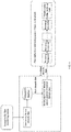
- FIG. 6 is a schematic diagram of a testing process of a traffic flow monitoring system provided by an embodiment of the present application. As shown in FIG. 6 , the test device is in communication connection with the first traffic flow monitoring system, and the test device is in communication connection with the second traffic flow monitoring system. Multiple processing components are included in the first traffic flow monitoring system, such as: a platform bottom-level basic component, a persistent data processing component, distributed data storage component, and so on.
- the test device monitors the real obstacle data from the second traffic flow monitoring system, sets tags for the real obstacle data according to the current traffic flow type, and sorts and stores the real obstacle data in the database.
- the database may be located in the test device, or may be located in other devices other than the test device. It should be understood that the specific monitoring process is similar to the foregoing embodiment, and will not be repeated here.
- the test device when the test device needs to test the first traffic flow monitoring system, it obtains the real obstacle data with a label consistent with the traffic flow type of the scene to be tested according to the traffic flow type of the scene to be tested from the database.
- the test device modifies the real obstacle data and generates the simulated obstacle data. Among them, the modifying process of the obstacle data may refer to the detailed description of the foregoing embodiment, which will not be repeated here.
- the test device sends the generated simulated obstacle data to the first traffic flow monitoring system.
- the first traffic flow monitoring system uses the aforementioned multiple processing components to process the simulated obstacle data, and then outputs the monitoring result.
- the test device may also determine the test result for the link connectivity of the first traffic flow monitoring system according to whether the first traffic flow monitoring system outputs the monitoring result. Exemplarily, it is determined that a link connectivity between the multiple processing components in the first traffic flow monitoring system is normal if the first traffic flow monitoring system outputs a monitoring result; and it is determined that a link connectivity between the multiple processing components in the first traffic flow monitoring system is abnormal if the first traffic flow monitoring system does not output a monitoring result. In this way, the test for the link connectivity of the first traffic flow monitoring system is realized.
- FIG. 7 is a schematic diagram of a traffic flow visualization display interface provided by an embodiment of the present application.
- the monitoring results of the first traffic flow monitoring system may be visually displayed in real time (as shown in the right area in FIG. 7 ).
- real-time data statistics and cumulative data statistics may also be displayed (as shown in the left area in FIG. 7 ).
- the display interface shown in FIG. 7 is only a possible example, and the embodiment of the present application does not limit the display form and the display content of the visualization interface.
- the first traffic flow monitoring system displays the visual monitoring results as shown in FIG. 7 , if yes, it is determined that the link connectivity of the first traffic flow monitoring system is normal, if no, it is determined that the link connectivity of the first traffic flow monitoring system is abnormal.
- FIG. 8A is a schematic structural diagram of an apparatus for testing a traffic flow monitoring system provided by an embodiment of the present application.
- the apparatus in this embodiment may be in a form of software and/or hardware, and the apparatus may be used as a test device or integrated into the test device.
- the apparatus for testing a traffic flow monitoring system 800 provided in this embodiment includes an obtaining module 801, a processing module 802, and a sending module 803.
- the obtaining module 801 is configured to obtain real obstacle data collected in a real traffic scene
- the apparatus provided in this embodiment may be used to implement the technical solution in the method embodiment shown in FIG. 3 , and their implementation principles and technical effects are similar, and will not be repeated here.
- FIG. 8B is a schematic structural diagram of another apparatus for testing a traffic flow monitoring system provided by an embodiment of the present application, This embodiment refines the apparatus of the embodiment shown in FIG. 8A .
- the processing module 802 includes a modifying unit 8021; where the modifying unit 8021 is configured to modify the real obstacle data according to an interface rule of the first traffic flow monitoring system to obtain the simulated obstacle data.
- the interface rule is used to indicate an interface parameter and an interface data format of the first traffic flow monitoring system; the modifying unit 8021 is specifically configured to:
- the modifying unit 8021 is specifically configured to:
- the obtaining module 801 is specifically configured to obtain the real obstacle data from an online second traffic flow monitoring system, where the real obstacle data is collected by an on board device and/or a roadside device in the real traffic scene and sent to the second traffic flow monitoring system.
- the obtaining module 801 is specifically configured to obtain a receiving frequency of the first traffic flow monitoring system, and obtain the real obstacle data from the second traffic flow monitoring system according to the receiving frequency;
- the sending module 803 is specifically configured to send the simulated obstacle data to the first traffic flow monitoring system to be tested according to the receiving frequency.
- the processing module 802 further includes: a configuring unit 8022; the configuring unit 8022 is configured to obtain scene configuration information of the second traffic flow monitoring system, and configure the first traffic flow monitoring system using the scene configuration information; where the scene configuration information includes at least one of following: map information, road coordinate rule information, and roadside device information.
- the obtaining module 801 includes a determining unit 8011 and an obtaining unit 8012;
- the first traffic flow monitoring system includes multiple processing components; and the apparatus further includes a determining module 804, which is configured to:
- the apparatus of this embodiment can be used to execute the technical solutions in any of the foregoing method embodiments, and their implementation principles and technical effects are similar, and will not be repeated here.
- the present application also provides an electronic device and a readable storage medium.
- the electronic device can be used as a test device.
- the present application also provides a computer program product, where the computer program product includes: a computer program, and a computer program is stored in a readable storage medium, at least one processor of the electronic device can read the computer program from the readable storage medium, and at least one processor executes the computer program to make the electronic device execute the solution provided by any of the above embodiments
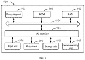
- FIG. 9 shows a schematic block diagram of an example electronic device 900 which can be used to implement embodiments of the present application.
- the electronic device is intended to represent various forms of digital computers, such as a laptop computer, a desktop computer, a workbench, a personal digital assistant, a server, a blade server, a mainframe computer, and other suitable computers.
- the electronic device can also represent various forms of mobile apparatus, such as a personal digital assistant, a cellular phone, a smart phone, a wearable device, and other similar computing apparatus.
- the components, their connections and relationships, and their functions herein are merely examples, and are not intended to limit an implementation of the present application described and/or claimed herein.
- the electronic device 900 includes a computing unit 901, which may perform various appropriate actions and processes according to a computer program stored in a read-only memory (ROM) 902 or a computer program loaded from a storage unit 908 into a random access memory (RAM) 903.
- ROM read-only memory
- RAM random access memory
- various programs and data required for the operation of the electronic device 900 may also be stored.
- the computing unit 901, the ROM 902, and the RAM 903 are connected to each other through a bus 904.
- An input/output (I/O) interface 905 is also connected to the bus 904.
- Multiple components in the device 900 are connected to the I/O interface 905, including: an inputting unit 906, such as a keyboard, a mouse, etc.; an outputting unit 907, such as various types of displays, speakers, etc.; and a storage unit 908, such as a magnetic disk, an optical disk, etc.; and a communicating unit 909, such as an network card, a modem, a wireless communication transceiver, etc.
- the communicating unit 909 allows the device 900 to exchange information/data with other devices through a computer network such as the Internet and/or various telecommunication networks.
- the computing unit 901 may be various general and/or special-purpose processing components with processing and computing capabilities. Some examples of the computing unit 901 include, but are not limited to, a central processing unit (CPU), a graphics processing unit (GPU), various dedicated artificial intelligence (AI) computing chips, various computing units that run machine learning model algorithms, and digital signal processing (DSP), as well as any appropriate processor, a controller, a microcontroller, etc.
- the computing unit 901 executes the various methods and processes described above, such as the method for testing a traffic flow monitoring system.
- the method for testing a traffic flow monitoring system be implemented as a computer software program, which is tangibly contained in a machine-readable medium, such as the storage unit 908.
- part or all of the computer program may be loaded and/or installed on the device 900 via the ROM 902 and/or the communicating unit 909.
- the computer program When the computer program is loaded into the RAM 903 and executed by the computing unit 901, one or more steps of the method for testing a traffic flow monitoring system described above may be executed.
- the computing unit 901 may be configured to execute the method for testing a traffic flow monitoring system through any other suitable means (for example, by a firmware).
- These various embodiments may include: being implemented in one or more computer programs, the one or more computer programs may be executed and/or interpreted on a programmable system including at least one programmable processor, the programmable processor may be a dedicated or general-purpose programmable processor that can receive data and instructions from a storage system, at least one input device, and at least one output device, and transmit data and instructions to the storage system, the at least one input device, and the at least one output device.
- the program code used to implement the method of the present application can be written in any combination of one or more programming languages.
- the program code can be provided to a processor or a controller of a general-purpose computer, a special-purpose computer, or other programmable data processing apparatus, so that when the program code is executed by the processor or the controller, functions specified in the flowcharts and/or block diagrams are implemented.
- the program code may be executed entirely on a machine, partly executed on the machine, partly executed on the machine and partly executed on a remote machine as an independent software package, or entirely executed on a remote machine or a server.
- a machine-readable medium may be a tangible medium, which may contain or store a program for use by an instruction execution system, apparatus, or device or in combination with an instruction execution system, apparatus, or device.
- the machine-readable medium may be a machine-readable signal medium or a machine-readable storage medium.
- the machine-readable medium may include, but is not limited to, an electronic, magnetic, optical, electromagnetic, infrared, or a semiconductor system, apparatus, or device, or any suitable combination of the foregoing.
- machine-readable storage media would include electrical connections based on one or more wires, a portable computer disk, a hard disk, a random access memory (RAM), a read-only memory (ROM), a erasable programmable read-only memory (EPROM or flash memory), an optical fiber, a portable compact disk read-only memory (CD-ROM), an optical storage device, a magnetic storage device, or any suitable combination of the foregoing.
- RAM random access memory
- ROM read-only memory
- EPROM or flash memory erasable programmable read-only memory
- CD-ROM portable compact disk read-only memory
- magnetic storage device or any suitable combination of the foregoing.
- the systems and techniques described herein may be implemented on a computer, where the computer has: a display apparatus (for example, a CRT (cathode ray tube) or an LCD (liquid crystal display) monitor) for displaying information to users; and a keyboard and a pointing apparatus (for example, a mouse or a trackball) though which users may provide input to the computer.
- a display apparatus for example, a CRT (cathode ray tube) or an LCD (liquid crystal display) monitor
- a keyboard and a pointing apparatus for example, a mouse or a trackball
- Other types of apparatus may also be used to provide interaction with users; for example, the feedback provided to users may be any form of sensing feedback (for example, visual feedback, audible feedback, or tactile feedback); and the input from users may be received in any form (including sound input, voice input, or tactile input).
- the systems and techniques described herein may be implemented in a computing system that includes a back end component (for example, a data server), or a computing system that includes a middleware component (for example, an application server), or a computing system that includes a front end component (for example, a user computer with a graphical user interface or a web browser, through which the user can interact with the implementations of the systems and techniques described herein), or a computing system that includes any combination of such back end component, middleware component, or front end component.
- System components may be connected to each other by any form or medium of digital data communication (for example, a communication network). Examples of the communication network include: a local area network (LAN), a wide area network (WAN) and Internet.
- a computer system may include a client and a server.
- the client and the server are generally far from each other and usually perform interactions through a communication network.
- a relationship between the client and the server is generated by a computer program running on corresponding computers and having a client-server relationship.
- the server may be a cloud server, also known as a cloud computing server or a cloud host, which is a host product in the cloud computing service system to solve the disadvantages of difficult management and weak business scalability in a traditional physical host and Virtual Private Server (VPS for short) service.
- the server may also be a server of a distributed system, or a server combined with a blockchain.
Landscapes
- Engineering & Computer Science (AREA)
- Physics & Mathematics (AREA)
- General Physics & Mathematics (AREA)
- Theoretical Computer Science (AREA)
- Analytical Chemistry (AREA)
- Chemical & Material Sciences (AREA)
- Business, Economics & Management (AREA)
- Multimedia (AREA)
- Tourism & Hospitality (AREA)
- General Engineering & Computer Science (AREA)
- Quality & Reliability (AREA)
- Computer Hardware Design (AREA)
- Economics (AREA)
- Health & Medical Sciences (AREA)
- General Health & Medical Sciences (AREA)
- Human Resources & Organizations (AREA)
- Marketing (AREA)
- Primary Health Care (AREA)
- Strategic Management (AREA)
- General Business, Economics & Management (AREA)
- Traffic Control Systems (AREA)
- Operations Research (AREA)
Applications Claiming Priority (1)
| Application Number | Priority Date | Filing Date | Title |
|---|---|---|---|
| CN202110247184.1A CN113032249B (zh) | 2021-03-05 | 2021-03-05 | 交通流量监测系统的测试方法、装置及设备 |
Publications (3)
| Publication Number | Publication Date |
|---|---|
| EP3933801A2 true EP3933801A2 (fr) | 2022-01-05 |
| EP3933801A3 EP3933801A3 (fr) | 2022-03-23 |
| EP3933801B1 EP3933801B1 (fr) | 2023-11-08 |
Family
ID=76468336
Family Applications (1)
| Application Number | Title | Priority Date | Filing Date |
|---|---|---|---|
| EP21193479.9A Active EP3933801B1 (fr) | 2021-03-05 | 2021-08-27 | Procédé, appareil et dispositif de test de système de surveillance de flux de trafic |
Country Status (5)
| Country | Link |
|---|---|
| US (1) | US12106577B2 (fr) |
| EP (1) | EP3933801B1 (fr) |
| JP (1) | JP7267363B2 (fr) |
| KR (1) | KR102606423B1 (fr) |
| CN (1) | CN113032249B (fr) |
Families Citing this family (9)
| Publication number | Priority date | Publication date | Assignee | Title |
|---|---|---|---|---|
| CN114092915B (zh) * | 2021-11-26 | 2023-06-23 | 阿波罗智联(北京)科技有限公司 | 一种路口交通流量验证方法、装置、设备及存储介质 |
| CN114244741B (zh) * | 2021-12-16 | 2023-11-14 | 阿波罗智联(北京)科技有限公司 | 一种链路测试方法、装置、系统、电子设备及存储介质 |
| CN114443402A (zh) * | 2021-12-27 | 2022-05-06 | 广东艾科智泊科技股份有限公司 | 一种基于mock的停车场模拟测试方法 |
| CN114363207A (zh) * | 2021-12-28 | 2022-04-15 | 阿波罗智联(北京)科技有限公司 | 云控平台的测试方法、装置、设备、存储介质及程序 |
| CN115550980A (zh) * | 2022-09-09 | 2022-12-30 | 中科南京移动通信与计算创新研究院 | 虚实协同通信测试系统、虚实协同通信测试方法及电子设备 |
| CN116320442A (zh) * | 2023-03-30 | 2023-06-23 | 济南浪潮数据技术有限公司 | 一种视频流数据的生成方法、装置及介质 |
| CN116738812B (zh) * | 2023-08-14 | 2023-11-21 | 中科三清科技有限公司 | 情景模拟系统、计算平台和存储介质 |
| CN118468442B (zh) * | 2024-05-17 | 2025-12-16 | 中国电子科技集团公司信息科学研究院 | 一种面向无人机智能水平测试的仿真场景建模方法和系统 |
| CN119512956B (zh) * | 2024-11-15 | 2025-08-29 | 北京曦和安行软件技术有限公司 | 一种模拟发送坐标的方法及系统、计算机设备 |
Family Cites Families (18)
| Publication number | Priority date | Publication date | Assignee | Title |
|---|---|---|---|---|
| US7786855B2 (en) * | 2005-08-08 | 2010-08-31 | University Of Washington Through Its Center For Commercialization | Mobile system and method for traffic detector simulations |
| CN103473925B (zh) * | 2013-08-28 | 2016-08-10 | 惠州市德赛工业发展有限公司 | 一种道路车辆检测系统的验证方法 |
| CN104539487B (zh) | 2015-01-20 | 2018-04-17 | 成都益联科创科技有限公司 | 一种基于云平台的系统测试及可靠性评估方法 |
| CN107134006B (zh) | 2016-02-29 | 2020-11-24 | 株式会社理光 | 创建物理场景模型的方法和装置、辅助驾驶的方法和装置 |
| CN206772594U (zh) * | 2016-12-14 | 2017-12-19 | 特路(北京)科技有限公司 | 自动驾驶车辆避让动态障碍物能力的测试场 |
| US20190164007A1 (en) * | 2017-11-30 | 2019-05-30 | TuSimple | Human driving behavior modeling system using machine learning |
| KR102145723B1 (ko) | 2017-12-15 | 2020-08-19 | 주식회사 웨이티즈 | V2x 적용 자율협력도로와 커넥티드카 시험 시스템 및 방법 |
| WO2019151427A1 (fr) | 2018-02-02 | 2019-08-08 | パナソニック インテレクチュアル プロパティ コーポレーション オブ アメリカ | Procédé de transmission d'informations et dispositif client |
| JP7059684B2 (ja) | 2018-02-23 | 2022-04-26 | トヨタ自動車株式会社 | 異常検知データ識別装置、および異常識別システム |
| CN108389399A (zh) * | 2018-04-23 | 2018-08-10 | 白冰 | 一种智能交通车流量数据统计方法 |
| US10816979B2 (en) | 2018-08-24 | 2020-10-27 | Baidu Usa Llc | Image data acquisition logic of an autonomous driving vehicle for capturing image data using cameras |
| EP3621052B1 (fr) * | 2018-09-05 | 2026-01-21 | VITRONIC Machine Vision GmbH | Procédé d'analyse du comportement routier de véhicules à moteur, dont de véhicules autonomes |
| CN109714421B (zh) | 2018-12-28 | 2021-08-03 | 国汽(北京)智能网联汽车研究院有限公司 | 基于车路协同的智能网联汽车运行系统 |
| CN110781578B (zh) | 2019-09-23 | 2024-03-29 | 同济大学 | 一种基于事故场景的智能网联车算法的测试及评价方法 |
| CN110798449B (zh) | 2019-09-25 | 2021-10-26 | 苏州云控车路科技有限公司 | 智能网联汽车云控系统测试方法 |
| CN110853393B (zh) * | 2019-11-26 | 2020-12-11 | 清华大学 | 智能网联车辆测试场数据采集与融合方法及系统 |
| CN111857094B (zh) * | 2020-07-17 | 2021-10-22 | 联陆智能交通科技(上海)有限公司 | 一种车载单元测试软件的系统及方法 |
| CN112188440B (zh) * | 2020-09-30 | 2022-01-25 | 中国汽车工程研究院股份有限公司 | 一种车路协同平行仿真测试方法及系统 |
-
2021
- 2021-03-05 CN CN202110247184.1A patent/CN113032249B/zh active Active
- 2021-08-27 EP EP21193479.9A patent/EP3933801B1/fr active Active
- 2021-08-31 US US17/462,065 patent/US12106577B2/en active Active
- 2021-09-06 JP JP2021144902A patent/JP7267363B2/ja active Active
- 2021-09-06 KR KR1020210118147A patent/KR102606423B1/ko not_active Ceased
Also Published As
| Publication number | Publication date |
|---|---|
| EP3933801B1 (fr) | 2023-11-08 |
| CN113032249A (zh) | 2021-06-25 |
| JP7267363B2 (ja) | 2023-05-01 |
| CN113032249B (zh) | 2023-03-24 |
| KR20210128952A (ko) | 2021-10-27 |
| US12106577B2 (en) | 2024-10-01 |
| JP2022000776A (ja) | 2022-01-04 |
| KR102606423B1 (ko) | 2023-11-24 |
| EP3933801A3 (fr) | 2022-03-23 |
| US20210390321A1 (en) | 2021-12-16 |
Similar Documents
| Publication | Publication Date | Title |
|---|---|---|
| US12106577B2 (en) | Method, apparatus, and device for testing traffic flow monitoring system | |
| CN110471979B (zh) | 基于多源仿真数据聚集与挖掘的电网信息展示仿真系统 | |
| EP3937077A1 (fr) | Procédé de détection de marquage de voie, appareil, dispositif électronique, support d'enregistrement et véhicule | |
| CN112530021B (zh) | 用于处理数据的方法、装置、设备以及存储介质 | |
| CN105590160A (zh) | 一种基于gis的三维应急指挥方法及其系统 | |
| EP4024362A2 (fr) | Procédé et appareil de surveillance de défaillance pour signaux lumineux, dispositif électronique et support de stockage | |
| EP3933802A2 (fr) | Procédé, appareil et dispositif de test de système de surveillance de flux de trafic | |
| US20230211776A1 (en) | Method for determining attribute value of obstacle in vehicle infrastructure cooperation, device and autonomous driving vehicle | |
| CN114581827A (zh) | 一种异常行为预警系统、方法、设备及介质 | |
| US20230169680A1 (en) | Beijing baidu netcom science technology co., ltd. | |
| US20200219389A1 (en) | Visualiziing real-time intersection occupancy and calculated analytics in 3d | |
| CN117369427A (zh) | 一种自动驾驶可视化方法、装置、系统及存储介质 | |
| CN118379675A (zh) | 一种踩踏风险预警方法、装置、计算机设备及存储介质 | |
| CN118429589A (zh) | 基于像素流的数字孪生系统、方法、设备及存储介质 | |
| CN114120651B (zh) | 用于测试感知目标数的方法、装置、设备、介质和产品 | |
| EP3979227A2 (fr) | Dispositif mobile et prodédé d'assistance pour l'entraînement à la conduite, dipositif électronique, et produit programme d'ordinateur | |
| KR20220030966A (ko) | 어노테이션 능력 정보 결정 방법, 장치 및 전자 기기, 컴퓨터 판독 가능 저장 매체 및 컴퓨터 프로그램 | |
| CN114353853A (zh) | 用于确定检测精度的方法、装置及计算机程序产品 | |
| CN113723585A (zh) | 人口预测方法、装置、电子设备和存储介质 | |
| CN117109623A (zh) | 一种智能穿戴式导航交互方法、系统及介质 | |
| KR20220073712A (ko) | 교통량의 획득 방법, 장치 및 전자 기기 | |
| EP4030142A2 (fr) | Procédé de génération d'informations de navigation, appareil de génération d'informations de navigation, dispositif, support et produit | |
| CN114546575A (zh) | 对象显示方法、装置、设备、存储介质以及程序产品 | |
| CN117270803A (zh) | 数据处理方法、装置、电子设备及存储介质 | |
| CN117119406A (zh) | 基于v2x的车联网信息服务平台及方法 |
Legal Events
| Date | Code | Title | Description |
|---|---|---|---|
| PUAI | Public reference made under article 153(3) epc to a published international application that has entered the european phase |
Free format text: ORIGINAL CODE: 0009012 |
|
| STAA | Information on the status of an ep patent application or granted ep patent |
Free format text: STATUS: REQUEST FOR EXAMINATION WAS MADE |
|
| 17P | Request for examination filed |
Effective date: 20210827 |
|
| AK | Designated contracting states |
Kind code of ref document: A2 Designated state(s): AL AT BE BG CH CY CZ DE DK EE ES FI FR GB GR HR HU IE IS IT LI LT LU LV MC MK MT NL NO PL PT RO RS SE SI SK SM TR |
|
| PUAL | Search report despatched |
Free format text: ORIGINAL CODE: 0009013 |
|
| AK | Designated contracting states |
Kind code of ref document: A3 Designated state(s): AL AT BE BG CH CY CZ DE DK EE ES FI FR GB GR HR HU IE IS IT LI LT LU LV MC MK MT NL NO PL PT RO RS SE SI SK SM TR |
|
| RIC1 | Information provided on ipc code assigned before grant |
Ipc: G06V 20/58 20220101ALI20220216BHEP Ipc: G06V 20/54 20220101ALI20220216BHEP Ipc: G08G 1/04 20060101ALI20220216BHEP Ipc: G08G 1/01 20060101AFI20220216BHEP |
|
| STAA | Information on the status of an ep patent application or granted ep patent |
Free format text: STATUS: EXAMINATION IS IN PROGRESS |
|
| 17Q | First examination report despatched |
Effective date: 20221104 |
|
| GRAP | Despatch of communication of intention to grant a patent |
Free format text: ORIGINAL CODE: EPIDOSNIGR1 |
|
| STAA | Information on the status of an ep patent application or granted ep patent |
Free format text: STATUS: GRANT OF PATENT IS INTENDED |
|
| INTG | Intention to grant announced |
Effective date: 20230525 |
|
| GRAS | Grant fee paid |
Free format text: ORIGINAL CODE: EPIDOSNIGR3 |
|
| GRAA | (expected) grant |
Free format text: ORIGINAL CODE: 0009210 |
|
| STAA | Information on the status of an ep patent application or granted ep patent |
Free format text: STATUS: THE PATENT HAS BEEN GRANTED |
|
| P01 | Opt-out of the competence of the unified patent court (upc) registered |
Effective date: 20230920 |
|
| AK | Designated contracting states |
Kind code of ref document: B1 Designated state(s): AL AT BE BG CH CY CZ DE DK EE ES FI FR GB GR HR HU IE IS IT LI LT LU LV MC MK MT NL NO PL PT RO RS SE SI SK SM TR |
|
| REG | Reference to a national code |
Ref country code: GB Ref legal event code: FG4D |
|
| REG | Reference to a national code |
Ref country code: CH Ref legal event code: EP |
|
| REG | Reference to a national code |
Ref country code: DE Ref legal event code: R096 Ref document number: 602021006602 Country of ref document: DE |
|
| REG | Reference to a national code |
Ref country code: IE Ref legal event code: FG4D |
|
| REG | Reference to a national code |
Ref country code: LT Ref legal event code: MG9D |
|
| REG | Reference to a national code |
Ref country code: NL Ref legal event code: MP Effective date: 20231108 |
|
| PG25 | Lapsed in a contracting state [announced via postgrant information from national office to epo] |
Ref country code: GR Free format text: LAPSE BECAUSE OF FAILURE TO SUBMIT A TRANSLATION OF THE DESCRIPTION OR TO PAY THE FEE WITHIN THE PRESCRIBED TIME-LIMIT Effective date: 20240209 |
|
| PG25 | Lapsed in a contracting state [announced via postgrant information from national office to epo] |
Ref country code: IS Free format text: LAPSE BECAUSE OF FAILURE TO SUBMIT A TRANSLATION OF THE DESCRIPTION OR TO PAY THE FEE WITHIN THE PRESCRIBED TIME-LIMIT Effective date: 20240308 |
|
| PG25 | Lapsed in a contracting state [announced via postgrant information from national office to epo] |
Ref country code: LT Free format text: LAPSE BECAUSE OF FAILURE TO SUBMIT A TRANSLATION OF THE DESCRIPTION OR TO PAY THE FEE WITHIN THE PRESCRIBED TIME-LIMIT Effective date: 20231108 |
|
| REG | Reference to a national code |
Ref country code: AT Ref legal event code: MK05 Ref document number: 1630365 Country of ref document: AT Kind code of ref document: T Effective date: 20231108 |
|
| PG25 | Lapsed in a contracting state [announced via postgrant information from national office to epo] |
Ref country code: NL Free format text: LAPSE BECAUSE OF FAILURE TO SUBMIT A TRANSLATION OF THE DESCRIPTION OR TO PAY THE FEE WITHIN THE PRESCRIBED TIME-LIMIT Effective date: 20231108 |
|
| PG25 | Lapsed in a contracting state [announced via postgrant information from national office to epo] |
Ref country code: AT Free format text: LAPSE BECAUSE OF FAILURE TO SUBMIT A TRANSLATION OF THE DESCRIPTION OR TO PAY THE FEE WITHIN THE PRESCRIBED TIME-LIMIT Effective date: 20231108 |
|
| PG25 | Lapsed in a contracting state [announced via postgrant information from national office to epo] |
Ref country code: ES Free format text: LAPSE BECAUSE OF FAILURE TO SUBMIT A TRANSLATION OF THE DESCRIPTION OR TO PAY THE FEE WITHIN THE PRESCRIBED TIME-LIMIT Effective date: 20231108 |
|
| PG25 | Lapsed in a contracting state [announced via postgrant information from national office to epo] |
Ref country code: NL Free format text: LAPSE BECAUSE OF FAILURE TO SUBMIT A TRANSLATION OF THE DESCRIPTION OR TO PAY THE FEE WITHIN THE PRESCRIBED TIME-LIMIT Effective date: 20231108 Ref country code: LT Free format text: LAPSE BECAUSE OF FAILURE TO SUBMIT A TRANSLATION OF THE DESCRIPTION OR TO PAY THE FEE WITHIN THE PRESCRIBED TIME-LIMIT Effective date: 20231108 Ref country code: IS Free format text: LAPSE BECAUSE OF FAILURE TO SUBMIT A TRANSLATION OF THE DESCRIPTION OR TO PAY THE FEE WITHIN THE PRESCRIBED TIME-LIMIT Effective date: 20240308 Ref country code: GR Free format text: LAPSE BECAUSE OF FAILURE TO SUBMIT A TRANSLATION OF THE DESCRIPTION OR TO PAY THE FEE WITHIN THE PRESCRIBED TIME-LIMIT Effective date: 20240209 Ref country code: ES Free format text: LAPSE BECAUSE OF FAILURE TO SUBMIT A TRANSLATION OF THE DESCRIPTION OR TO PAY THE FEE WITHIN THE PRESCRIBED TIME-LIMIT Effective date: 20231108 Ref country code: BG Free format text: LAPSE BECAUSE OF FAILURE TO SUBMIT A TRANSLATION OF THE DESCRIPTION OR TO PAY THE FEE WITHIN THE PRESCRIBED TIME-LIMIT Effective date: 20240208 Ref country code: AT Free format text: LAPSE BECAUSE OF FAILURE TO SUBMIT A TRANSLATION OF THE DESCRIPTION OR TO PAY THE FEE WITHIN THE PRESCRIBED TIME-LIMIT Effective date: 20231108 Ref country code: PT Free format text: LAPSE BECAUSE OF FAILURE TO SUBMIT A TRANSLATION OF THE DESCRIPTION OR TO PAY THE FEE WITHIN THE PRESCRIBED TIME-LIMIT Effective date: 20240308 |
|
| PG25 | Lapsed in a contracting state [announced via postgrant information from national office to epo] |
Ref country code: SE Free format text: LAPSE BECAUSE OF FAILURE TO SUBMIT A TRANSLATION OF THE DESCRIPTION OR TO PAY THE FEE WITHIN THE PRESCRIBED TIME-LIMIT Effective date: 20231108 Ref country code: RS Free format text: LAPSE BECAUSE OF FAILURE TO SUBMIT A TRANSLATION OF THE DESCRIPTION OR TO PAY THE FEE WITHIN THE PRESCRIBED TIME-LIMIT Effective date: 20231108 Ref country code: PL Free format text: LAPSE BECAUSE OF FAILURE TO SUBMIT A TRANSLATION OF THE DESCRIPTION OR TO PAY THE FEE WITHIN THE PRESCRIBED TIME-LIMIT Effective date: 20231108 Ref country code: NO Free format text: LAPSE BECAUSE OF FAILURE TO SUBMIT A TRANSLATION OF THE DESCRIPTION OR TO PAY THE FEE WITHIN THE PRESCRIBED TIME-LIMIT Effective date: 20240208 Ref country code: LV Free format text: LAPSE BECAUSE OF FAILURE TO SUBMIT A TRANSLATION OF THE DESCRIPTION OR TO PAY THE FEE WITHIN THE PRESCRIBED TIME-LIMIT Effective date: 20231108 Ref country code: HR Free format text: LAPSE BECAUSE OF FAILURE TO SUBMIT A TRANSLATION OF THE DESCRIPTION OR TO PAY THE FEE WITHIN THE PRESCRIBED TIME-LIMIT Effective date: 20231108 |
|
| PG25 | Lapsed in a contracting state [announced via postgrant information from national office to epo] |
Ref country code: DK Free format text: LAPSE BECAUSE OF FAILURE TO SUBMIT A TRANSLATION OF THE DESCRIPTION OR TO PAY THE FEE WITHIN THE PRESCRIBED TIME-LIMIT Effective date: 20231108 |
|
| PG25 | Lapsed in a contracting state [announced via postgrant information from national office to epo] |
Ref country code: CZ Free format text: LAPSE BECAUSE OF FAILURE TO SUBMIT A TRANSLATION OF THE DESCRIPTION OR TO PAY THE FEE WITHIN THE PRESCRIBED TIME-LIMIT Effective date: 20231108 |
|
| PG25 | Lapsed in a contracting state [announced via postgrant information from national office to epo] |
Ref country code: SK Free format text: LAPSE BECAUSE OF FAILURE TO SUBMIT A TRANSLATION OF THE DESCRIPTION OR TO PAY THE FEE WITHIN THE PRESCRIBED TIME-LIMIT Effective date: 20231108 |
|
| PG25 | Lapsed in a contracting state [announced via postgrant information from national office to epo] |
Ref country code: SM Free format text: LAPSE BECAUSE OF FAILURE TO SUBMIT A TRANSLATION OF THE DESCRIPTION OR TO PAY THE FEE WITHIN THE PRESCRIBED TIME-LIMIT Effective date: 20231108 Ref country code: SK Free format text: LAPSE BECAUSE OF FAILURE TO SUBMIT A TRANSLATION OF THE DESCRIPTION OR TO PAY THE FEE WITHIN THE PRESCRIBED TIME-LIMIT Effective date: 20231108 Ref country code: RO Free format text: LAPSE BECAUSE OF FAILURE TO SUBMIT A TRANSLATION OF THE DESCRIPTION OR TO PAY THE FEE WITHIN THE PRESCRIBED TIME-LIMIT Effective date: 20231108 Ref country code: IT Free format text: LAPSE BECAUSE OF FAILURE TO SUBMIT A TRANSLATION OF THE DESCRIPTION OR TO PAY THE FEE WITHIN THE PRESCRIBED TIME-LIMIT Effective date: 20231108 Ref country code: EE Free format text: LAPSE BECAUSE OF FAILURE TO SUBMIT A TRANSLATION OF THE DESCRIPTION OR TO PAY THE FEE WITHIN THE PRESCRIBED TIME-LIMIT Effective date: 20231108 Ref country code: DK Free format text: LAPSE BECAUSE OF FAILURE TO SUBMIT A TRANSLATION OF THE DESCRIPTION OR TO PAY THE FEE WITHIN THE PRESCRIBED TIME-LIMIT Effective date: 20231108 Ref country code: CZ Free format text: LAPSE BECAUSE OF FAILURE TO SUBMIT A TRANSLATION OF THE DESCRIPTION OR TO PAY THE FEE WITHIN THE PRESCRIBED TIME-LIMIT Effective date: 20231108 |
|
| REG | Reference to a national code |
Ref country code: DE Ref legal event code: R097 Ref document number: 602021006602 Country of ref document: DE |
|
| PLBE | No opposition filed within time limit |
Free format text: ORIGINAL CODE: 0009261 |
|
| STAA | Information on the status of an ep patent application or granted ep patent |
Free format text: STATUS: NO OPPOSITION FILED WITHIN TIME LIMIT |
|
| 26N | No opposition filed |
Effective date: 20240809 |
|
| PG25 | Lapsed in a contracting state [announced via postgrant information from national office to epo] |
Ref country code: SI Free format text: LAPSE BECAUSE OF FAILURE TO SUBMIT A TRANSLATION OF THE DESCRIPTION OR TO PAY THE FEE WITHIN THE PRESCRIBED TIME-LIMIT Effective date: 20231108 |
|
| PG25 | Lapsed in a contracting state [announced via postgrant information from national office to epo] |
Ref country code: SI Free format text: LAPSE BECAUSE OF FAILURE TO SUBMIT A TRANSLATION OF THE DESCRIPTION OR TO PAY THE FEE WITHIN THE PRESCRIBED TIME-LIMIT Effective date: 20231108 |
|
| REG | Reference to a national code |
Ref country code: CH Ref legal event code: PL |
|
| PG25 | Lapsed in a contracting state [announced via postgrant information from national office to epo] |
Ref country code: LU Free format text: LAPSE BECAUSE OF NON-PAYMENT OF DUE FEES Effective date: 20240827 |
|
| PG25 | Lapsed in a contracting state [announced via postgrant information from national office to epo] |
Ref country code: MC Free format text: LAPSE BECAUSE OF FAILURE TO SUBMIT A TRANSLATION OF THE DESCRIPTION OR TO PAY THE FEE WITHIN THE PRESCRIBED TIME-LIMIT Effective date: 20231108 Ref country code: CH Free format text: LAPSE BECAUSE OF NON-PAYMENT OF DUE FEES Effective date: 20240831 |
|
| REG | Reference to a national code |
Ref country code: BE Ref legal event code: MM Effective date: 20240831 |
|
| PG25 | Lapsed in a contracting state [announced via postgrant information from national office to epo] |
Ref country code: BE Free format text: LAPSE BECAUSE OF NON-PAYMENT OF DUE FEES Effective date: 20240831 |
|
| PGFP | Annual fee paid to national office [announced via postgrant information from national office to epo] |
Ref country code: FR Payment date: 20250603 Year of fee payment: 5 |
|
| PG25 | Lapsed in a contracting state [announced via postgrant information from national office to epo] |
Ref country code: IE Free format text: LAPSE BECAUSE OF NON-PAYMENT OF DUE FEES Effective date: 20240827 |
|
| PG25 | Lapsed in a contracting state [announced via postgrant information from national office to epo] |
Ref country code: FI Free format text: LAPSE BECAUSE OF FAILURE TO SUBMIT A TRANSLATION OF THE DESCRIPTION OR TO PAY THE FEE WITHIN THE PRESCRIBED TIME-LIMIT Effective date: 20231108 |
|
| PGFP | Annual fee paid to national office [announced via postgrant information from national office to epo] |
Ref country code: DE Payment date: 20250819 Year of fee payment: 5 |
|
| PG25 | Lapsed in a contracting state [announced via postgrant information from national office to epo] |
Ref country code: CY Free format text: LAPSE BECAUSE OF FAILURE TO SUBMIT A TRANSLATION OF THE DESCRIPTION OR TO PAY THE FEE WITHIN THE PRESCRIBED TIME-LIMIT; INVALID AB INITIO Effective date: 20210827 |
|
| PG25 | Lapsed in a contracting state [announced via postgrant information from national office to epo] |
Ref country code: HU Free format text: LAPSE BECAUSE OF FAILURE TO SUBMIT A TRANSLATION OF THE DESCRIPTION OR TO PAY THE FEE WITHIN THE PRESCRIBED TIME-LIMIT; INVALID AB INITIO Effective date: 20210827 |