EP3934005B1 - Système et procédé de test de flux électrique de batterie - Google Patents
Système et procédé de test de flux électrique de batterie Download PDFInfo
- Publication number
- EP3934005B1 EP3934005B1 EP21755881.6A EP21755881A EP3934005B1 EP 3934005 B1 EP3934005 B1 EP 3934005B1 EP 21755881 A EP21755881 A EP 21755881A EP 3934005 B1 EP3934005 B1 EP 3934005B1
- Authority
- EP
- European Patent Office
- Prior art keywords
- battery
- frequency
- impedance
- insulation resistance
- voltage
- Prior art date
- Legal status (The legal status is an assumption and is not a legal conclusion. Google has not performed a legal analysis and makes no representation as to the accuracy of the status listed.)
- Active
Links
Images




Classifications
-
- G—PHYSICS
- G01—MEASURING; TESTING
- G01R—MEASURING ELECTRIC VARIABLES; MEASURING MAGNETIC VARIABLES
- G01R31/00—Arrangements for testing electric properties; Arrangements for locating electric faults; Arrangements for electrical testing characterised by what is being tested not provided for elsewhere
- G01R31/36—Arrangements for testing, measuring or monitoring the electrical condition of accumulators or electric batteries, e.g. capacity or state of charge [SoC]
- G01R31/382—Arrangements for monitoring battery or accumulator variables, e.g. SoC
- G01R31/3835—Arrangements for monitoring battery or accumulator variables, e.g. SoC involving only voltage measurements
-
- G—PHYSICS
- G01—MEASURING; TESTING
- G01R—MEASURING ELECTRIC VARIABLES; MEASURING MAGNETIC VARIABLES
- G01R31/00—Arrangements for testing electric properties; Arrangements for locating electric faults; Arrangements for electrical testing characterised by what is being tested not provided for elsewhere
- G01R31/12—Testing dielectric strength or breakdown voltage ; Testing or monitoring effectiveness or level of insulation, e.g. of a cable or of an apparatus, for example using partial discharge measurements; Electrostatic testing
-
- G—PHYSICS
- G01—MEASURING; TESTING
- G01R—MEASURING ELECTRIC VARIABLES; MEASURING MAGNETIC VARIABLES
- G01R31/00—Arrangements for testing electric properties; Arrangements for locating electric faults; Arrangements for electrical testing characterised by what is being tested not provided for elsewhere
- G01R31/36—Arrangements for testing, measuring or monitoring the electrical condition of accumulators or electric batteries, e.g. capacity or state of charge [SoC]
- G01R31/3644—Constructional arrangements
- G01R31/3646—Constructional arrangements for indicating electrical conditions or variables, e.g. visual or audible indicators
-
- G—PHYSICS
- G01—MEASURING; TESTING
- G01R—MEASURING ELECTRIC VARIABLES; MEASURING MAGNETIC VARIABLES
- G01R31/00—Arrangements for testing electric properties; Arrangements for locating electric faults; Arrangements for electrical testing characterised by what is being tested not provided for elsewhere
- G01R31/36—Arrangements for testing, measuring or monitoring the electrical condition of accumulators or electric batteries, e.g. capacity or state of charge [SoC]
- G01R31/385—Arrangements for measuring battery or accumulator variables
-
- G—PHYSICS
- G01—MEASURING; TESTING
- G01R—MEASURING ELECTRIC VARIABLES; MEASURING MAGNETIC VARIABLES
- G01R31/00—Arrangements for testing electric properties; Arrangements for locating electric faults; Arrangements for electrical testing characterised by what is being tested not provided for elsewhere
- G01R31/36—Arrangements for testing, measuring or monitoring the electrical condition of accumulators or electric batteries, e.g. capacity or state of charge [SoC]
- G01R31/389—Measuring internal impedance, internal conductance or related variables
-
- G—PHYSICS
- G06—COMPUTING OR CALCULATING; COUNTING
- G06F—ELECTRIC DIGITAL DATA PROCESSING
- G06F1/00—Details not covered by groups G06F3/00 - G06F13/00 and G06F21/00
- G06F1/26—Power supply means, e.g. regulation thereof
- G06F1/28—Supervision thereof, e.g. detecting power-supply failure by out of limits supervision
-
- G—PHYSICS
- G06—COMPUTING OR CALCULATING; COUNTING
- G06F—ELECTRIC DIGITAL DATA PROCESSING
- G06F17/00—Digital computing or data processing equipment or methods, specially adapted for specific functions
- G06F17/10—Complex mathematical operations
-
- G—PHYSICS
- G06—COMPUTING OR CALCULATING; COUNTING
- G06F—ELECTRIC DIGITAL DATA PROCESSING
- G06F3/00—Input arrangements for transferring data to be processed into a form capable of being handled by the computer; Output arrangements for transferring data from processing unit to output unit, e.g. interface arrangements
- G06F3/01—Input arrangements or combined input and output arrangements for interaction between user and computer
- G06F3/048—Interaction techniques based on graphical user interfaces [GUI]
- G06F3/0484—Interaction techniques based on graphical user interfaces [GUI] for the control of specific functions or operations, e.g. selecting or manipulating an object, an image or a displayed text element, setting a parameter value or selecting a range
-
- H—ELECTRICITY
- H01—ELECTRIC ELEMENTS
- H01M—PROCESSES OR MEANS, e.g. BATTERIES, FOR THE DIRECT CONVERSION OF CHEMICAL ENERGY INTO ELECTRICAL ENERGY
- H01M10/00—Secondary cells; Manufacture thereof
- H01M10/42—Methods or arrangements for servicing or maintenance of secondary cells or secondary half-cells
- H01M10/4285—Testing apparatus
-
- H—ELECTRICITY
- H01—ELECTRIC ELEMENTS
- H01M—PROCESSES OR MEANS, e.g. BATTERIES, FOR THE DIRECT CONVERSION OF CHEMICAL ENERGY INTO ELECTRICAL ENERGY
- H01M10/00—Secondary cells; Manufacture thereof
- H01M10/42—Methods or arrangements for servicing or maintenance of secondary cells or secondary half-cells
- H01M10/44—Methods for charging or discharging
-
- H—ELECTRICITY
- H01—ELECTRIC ELEMENTS
- H01M—PROCESSES OR MEANS, e.g. BATTERIES, FOR THE DIRECT CONVERSION OF CHEMICAL ENERGY INTO ELECTRICAL ENERGY
- H01M10/00—Secondary cells; Manufacture thereof
- H01M10/42—Methods or arrangements for servicing or maintenance of secondary cells or secondary half-cells
- H01M10/48—Accumulators combined with arrangements for measuring, testing or indicating the condition of cells, e.g. the level or density of the electrolyte
-
- H—ELECTRICITY
- H01—ELECTRIC ELEMENTS
- H01M—PROCESSES OR MEANS, e.g. BATTERIES, FOR THE DIRECT CONVERSION OF CHEMICAL ENERGY INTO ELECTRICAL ENERGY
- H01M10/00—Secondary cells; Manufacture thereof
- H01M10/54—Reclaiming serviceable parts of waste accumulators
-
- H—ELECTRICITY
- H01—ELECTRIC ELEMENTS
- H01M—PROCESSES OR MEANS, e.g. BATTERIES, FOR THE DIRECT CONVERSION OF CHEMICAL ENERGY INTO ELECTRICAL ENERGY
- H01M2220/00—Batteries for particular applications
- H01M2220/20—Batteries in motive systems, e.g. vehicle, ship, plane
-
- Y—GENERAL TAGGING OF NEW TECHNOLOGICAL DEVELOPMENTS; GENERAL TAGGING OF CROSS-SECTIONAL TECHNOLOGIES SPANNING OVER SEVERAL SECTIONS OF THE IPC; TECHNICAL SUBJECTS COVERED BY FORMER USPC CROSS-REFERENCE ART COLLECTIONS [XRACs] AND DIGESTS
- Y02—TECHNOLOGIES OR APPLICATIONS FOR MITIGATION OR ADAPTATION AGAINST CLIMATE CHANGE
- Y02E—REDUCTION OF GREENHOUSE GAS [GHG] EMISSIONS, RELATED TO ENERGY GENERATION, TRANSMISSION OR DISTRIBUTION
- Y02E60/00—Enabling technologies; Technologies with a potential or indirect contribution to GHG emissions mitigation
- Y02E60/10—Energy storage using batteries
-
- Y—GENERAL TAGGING OF NEW TECHNOLOGICAL DEVELOPMENTS; GENERAL TAGGING OF CROSS-SECTIONAL TECHNOLOGIES SPANNING OVER SEVERAL SECTIONS OF THE IPC; TECHNICAL SUBJECTS COVERED BY FORMER USPC CROSS-REFERENCE ART COLLECTIONS [XRACs] AND DIGESTS
- Y02—TECHNOLOGIES OR APPLICATIONS FOR MITIGATION OR ADAPTATION AGAINST CLIMATE CHANGE
- Y02E—REDUCTION OF GREENHOUSE GAS [GHG] EMISSIONS, RELATED TO ENERGY GENERATION, TRANSMISSION OR DISTRIBUTION
- Y02E60/00—Enabling technologies; Technologies with a potential or indirect contribution to GHG emissions mitigation
- Y02E60/30—Hydrogen technology
- Y02E60/50—Fuel cells
-
- Y—GENERAL TAGGING OF NEW TECHNOLOGICAL DEVELOPMENTS; GENERAL TAGGING OF CROSS-SECTIONAL TECHNOLOGIES SPANNING OVER SEVERAL SECTIONS OF THE IPC; TECHNICAL SUBJECTS COVERED BY FORMER USPC CROSS-REFERENCE ART COLLECTIONS [XRACs] AND DIGESTS
- Y02—TECHNOLOGIES OR APPLICATIONS FOR MITIGATION OR ADAPTATION AGAINST CLIMATE CHANGE
- Y02W—CLIMATE CHANGE MITIGATION TECHNOLOGIES RELATED TO WASTEWATER TREATMENT OR WASTE MANAGEMENT
- Y02W30/00—Technologies for solid waste management
- Y02W30/50—Reuse, recycling or recovery technologies
- Y02W30/84—Recycling of batteries or fuel cells
Definitions
- the present disclosure relates to a technic of testing electricity flow for a used battery (e.g., waste battery, etc.), and more particularly, to a system of testing electricity flow of a used battery to check a state of charge and chargeability of a used battery before reusing or recycling and check whether there is any abnormality in electricity flow through an electrical resistance test and to a method of the same.
- a used battery e.g., waste battery, etc.
- JP H04 198783A relates to a method for determining the life of a lead-acid battery, and more particularly to a method for determining the service life by measuring the internal impedance of a lead-acid battery.
- KR 102029776 B1 relates to a method of detecting a life of a storage battery.
- US 2011/0191043 A1 describes an apparatus for checking insulation of a cell module assembly composed of a plurality of pouch cells.
- US 3 872 457 A relates to a battery monitor system for multi-cell batteries.
- the electricity flow test of the used battery is to check the current state of charge and chargeability, and to check whether there is any abnormality in the electricity flow through an electrical resistance test through connection to a charging equipment.
- Embodiments of the present disclosure are directed to a system and a method of testing electricity flow of a battery, the system and the method being capable of performing electricity flow tests of a used battery.
- Embodiments of the present disclosure are directed to a system and a method of testing electricity flow of a battery, the system and the method being capable of performing electricity flow tests of a used battery for an electric vehicle.
- a system of testing electricity flow of a battery is defined in claim 1.
- the system of testing electricity flow of a battery further includes: a battery voltage identifier configured to operate a battery voltage meter electrically connected thereto according to an instruction of the test item manager, and identify a voltage of the battery through the battery voltage meter; a voltage diagnoser configured to compare the voltage of the battery identified by the battery voltage identifier with a set voltage range and diagnose that it is normal when the identified battery voltage is within the set voltage range and otherwise, diagnose that it is abnormal; an insulation resistance identifier configured to operate an insulation resistance meter electrically connected thereto according to an instruction of the test item manager, and identify an insulation resistance of the battery through the insulation resistance meter; an insulation resistance diagnoser configured to compare the insulation resistance identified by the insulation resistance identifier with a set insulation resistance lower limit and diagnose that it is abnormal when the identified insulation resistance is lower than the set insulation resistance lower limit and diagnose that it is normal when the identified insulation resistance is higher than the set insulation resistance lower limit; and a conformance diagnoser configured to receive each diagnosis result output from the voltage diagnoser, the insulation resistance diagnoser,
- the test item manager provides an item setting screen to a user through a display device, the item setting screen including a field in which a battery type, the set voltage range according to the battery type, the insulation resistance lower limit, and the electricity flow upper limit may be input by a user or displayed, a field for displaying the battery voltaeg, the insulation resistance and the AC impedance identified by each of the identifiers, a field for displaying a state of charge, an electricity flow, and an insulation safety according to the disgnosis result of each of the diagnosers, and a field for displaying the final conformance result diagnosed by the conformance diagnoser.
- a method of testing electricity flow of a battery is defined in claim 4.
- a method of testing electricity flow of a battery further includes: identifying a voltage of the battery through a battery voltage meter connected thereto; comparing the voltage of the battery with a set voltage range to diagnose that it is normal when the voltage of the battery is within the set voltage range and otherwise, diagnose that it is abnormal; identifying an insulation resistance of the battery through an insulation resistance meter connected thereto; comparing the insulation resistance identified by the insulation resistance identifier with a set insulation resistance lower limit to diagnose that it is abnormal when the identified insulation resistance is lower than the set insulation resistance lower limit and diagnose that it is normal when the identified insulation resistance is higher than the set insulation resistance lower limit; and receiving a diagnosis result for the voltage of the battery and a diagnosis result for the insulation resistance of the battery and determining a final conformance result.
- a system and a method are capable of performing electricity flow tests of a waste battery for an electric vehicle at a low cost by using an AC power.
- unit in the specification may mean a hardware component or circuit.
- a battery used hereinbelow may mean a used battery (e.g., a waste battery, etc.) used in an electric vehicle, and a battery to be tested may be one of a battery cell, a battery module, or a battery pack.
- a used battery e.g., a waste battery, etc.
- a battery to be tested may be one of a battery cell, a battery module, or a battery pack.
- FIG. 1 is a block diagram illustrating a system of testing electricity flow of a battery according to an embodiment of the present disclosure.
- a system 100 of testing electricity flow of a battery according to an embodiment of the present disclosure includes a test item manager 110, a set value storage 120, a battery voltage identifier 130, an insulation resistance identifier 140, an impedance identifier 150, a voltage diagnoser (e.g., diagnose unit) 160, an insulation resistance diagnoser 170, an electricity flow diagnoser 180, a conformance diagnoser 190, and an AC impedance meter 230.
- a voltage diagnoser e.g., diagnose unit
- the system 100 when the AC impedance meter 230 is manufactured in a form detachable from the system 100 of the present disclosure, the system 100 according to an embodiment of the present disclosure may omit the AC impedance meter 230.
- the system of testing electricity flow of a battery uses only the AC impedance meter 230, the battery voltage identifier 130, the insulation resistance identifier 140, the voltage diagnoser 160, and the insulation resistance diagnoser 170 may be omitted.
- the test item manager 110 manages a set value, a measured value, a diagnostic value, and a final test value for each battery test item.
- the set value means a reference value for each test item for comparison with a measured value
- the measured value means a value measured for each test item, for example, a measured battery voltage, a measured battery insulation resistance, and a measured battery impedance.
- a diagnostic value is a result of comparison between the reference value and the measured value for each test item, and means pass (e.g., normal) or fail (e.g., abnormal).
- a final test value is a value indicating final conformance of the battery according to the diagnostic value, and means, for example, that it conforms (e.g., suitable, proper, appropriate, etc.) or non-conforms (e.g., unsuitable, non-proper, inappropriate, etc.).
- test item manager 110 registers a set value, which is a reference value for each test item, for each battery type according to a user's request input through a user input unit 10, and performs management such as modification (e.g., correction) or deletion of the set value.
- the test item manager 110 generates an item setting screen to be displayed externally through a display device 20, and the user may input and register a new battery type and set values for a new battery type through the item setting screen, and check the set values for each test item, various diagnostic values, and final test values for the battery to be tested through the item setting screen.
- FIGS. 6 and 7 are diagrams illustrating a screen for displaying test items and test results in the system of testing electricity flow of a battery according to an embodiment of the present disclosure. Referring to FIGS. 6 and 7
- a field (1) in which a battery ID (identification information) may be input by a user or a registered battery ID may be called to be displayed a field (2) in which a battery type may be input by a user or a registered battery type may be called to be displayed, a button (3) to call a new item setting screen for recording information of a new battery, a button (4) to delete the currently displayed battery information, a field (5) in which a set value for test items may be input by a user or a registered set value may be called to be displayed, and a button (6) to instruct the start of the test.
- the button (6) to instruct the start of the test is changed to "test reset" and displayed when the user clicks the button.
- a field indicated as "voltage range”, displaying upper and lower limits of a battery voltage for the corresponding battery type, a field, indicated as “capacity”, displaying a reference current value, a field, indicated as “electricity flow upper limit”, displaying an upper limit of an AC impedance, and a field, indicated as "insulation resistance lower limit”, displaying a lower limit of an insulation resistance.
- a field (7) in which a test progress level (e.g., runtime) is displayed a field (8), indicated as "state of charge”, displaying a measured battery voltage and a state of charge (SOC), a field (9), indicated as "electricity flow”, displaying a measured AC impedance, a field (10), indicated as “insulation safety”, displaying a measured insulation resistance, a field (11) displaying a diagnosis result according to each measurement value and a field (12) displaying the final result of the electricity flow test.
- a test progress level e.g., runtime
- the SOC is calculated using the battery voltage or is identified using an SOC table generated based on maximum and minimum voltages of the battery.
- the measured battery voltage is 27.72 V, which falls within the set voltage range of 24.20 V to 29.40 V, and thus is displayed as pass
- the AC impedance that is, electricity flow
- the measured insulation resistance exceeds the set value of 1.00 M ⁇ , and thus is displayed as pass. Accordingly, since all test items passed, the final test result is indicated as "conform/chargeable".
- the measured battery voltage is 27.71 V, which is out of the set voltage range of 288.00 V to 403.20 V, and thus is displayed as fail
- the AC impedance that is, electricity flow
- the measured insulation resistance exceeds the set value of 1.00 M ⁇ , and thus is displayed as pass. Accordingly, since there was an abnormality in one of all test items, the final test result is indicated as "non-conform/non-chargeable".
- the set value storage 120 matches the set value for each test item registered by the test item manager 110 with the corresponding battery type and stores it. It is obvious that the set value storage 120 may store the test result of the tested used battery.
- the system 100 of testing electricity flow of a battery has a measurement value identifier A for identifying a measurement value for each test item.
- Each identifier of the measurement value identifier A operates according to an instruction of the test item manager 110, and provides the identified measurement value to the test item manager 110.
- the measurement value identifier A includes a battery voltage identifier 130, an insulation resistance identifier 140, and an impedance identifier 150.
- the battery voltage identifier 130 controls operation of the battery voltage meter 210 to receive a measurement result measured by the battery voltage meter 210 and identify a battery voltage (e.g., a voltage of a battery cell or a battery module or a battery pack).
- a battery voltage e.g., a voltage of a battery cell or a battery module or a battery pack.
- the battery voltage meter 210 is a device for measuring a voltage of the battery by having one measuring terminal connected to a negative electrode of the battery and another measuring terminal connected to a positive electrode of the battery, and is a common battery voltage meter.
- the insulation resistance identifier 140 controls the operation of the battery voltage meter 210 to receive and identify an insulation resistance of the battery measured by the insulation resistance meter 220.
- the insulation resistance meter 220 is a device for measuring the insulation resistance of a common battery, for example, a device having one terminal connected to one of the positive or negative terminal of the battery and another terminal connected to a body of the battery to measure the insulation resistance of the battery.
- the impedance identifier 150 controls operation of the AC impedance meter 230 to receive a frequency of a plurality of currents supplied from the AC impedance meter 230 and a frequency of a voltage measured corresponding to the frequency of the supplied current, to identify a phase difference between the frequencies with respect to a current and a voltage of the same frequency, and then to identify an AC impedance by using a voltage and a current of a frequency that has no phase difference.
- the AC impedance represents the same value as a DC impedance with respect to a DC power by using the voltage and the current of a frequency having no phase difference.
- the system 100 of testing electricity flow of a battery includes a measurement value diagnoser B for diagnosing whether a measurement value for each test item passes or fails (e.g., normal or abnormal).
- Each diagnoser of the measurement value diagnoser B provides a diagnosis result to the test item manager 110.
- the measurement value diagnoser B includes a voltage diagnoser 160, an insulation resistance diagnoser 170, and an electricity flow diagnoser 180.
- the voltage diagnoser 160 compares the voltage detected by the battery voltage identifier 130 with a set voltage, that is, a set voltage range, and diagnoses whether the detected voltage is within the set voltage range.
- the voltage diagnoser 160 diagnoses that it is normal (e.g., pass) when the detected voltage is within the set voltage range, and otherwise, diagnoses that it is abnormal (e.g., fail).
- the insulation resistance diagnoser 170 compares the insulation resistance identified by the insulation resistance identifier 140 with the set insulation resistance, and when the identified insulation resistance is higher than the set insulation resistance, it is diagnosed as normal, and otherwise, it is diagnosed as abnormal.
- the electricity flow diagnoser 180 compares the AC impedance identified by the impedance identifier 150 with the set impedance, and when the determined AC impedance is lower than the set insulation resistance, it is diagnosed as normal, and otherwise, it is diagnosed as abnormal.
- the conformance diagnoser 190 receives each diagnosis result output from the voltage diagnoser 160, the insulation resistance diagnoser 170, and the electricity flow diagnoser 180, determines a final conformance result, and provides the final conformance result to the test item manager 110.
- the AC impedance meter 230 sequentially generates frequencies in a set frequency band in the order from the minimum frequency to the maximum frequency or from the maximum frequency to the minimum frequency, inputs them to the used battery 30, and provides an output frequency corresponding to the input frequency to the impedance identifier 150.
- FIG. 2 is a perspective view illustrating a system of testing electricity flow of a battery according to an embodiment of the present disclosure.
- the display device 20 is configured as a common monitor, and in the system 100 of testing electricity flow of a battery, a connection member of a plug or a socket to be electrically connected to terminals of each meter (e.g., measurement apparatus) 210, 220, 230 is provided.
- a connection member of a plug or a socket to be electrically connected to terminals of each meter (e.g., measurement apparatus) 210, 220, 230 is provided.
- the AC impedance meter 230 is configured, the system 100 of testing electricity flow of a battery will be configured unitarily (e.g., in a monolithic manner) with the AC impedance meter 230.
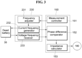
- FIG. 3 is a diagram illustrating in detail an impedance measurement configuration in a system of testing electricity flow of a battery according to an embodiment of the present disclosure
- FIGS. 4 and 5 are diagrams for explaining an impedance measuring principle in a system of testing electricity flow of a battery according to an embodiment of the present disclosure.
- An electrical flow test is to test a flow of an AC current, and the flow of the AC current is affected by an AC impedance. Since a battery is an electrochemical device that uses DC electricity and the test is to determine conformance of an electricity flow thereof, a resistance to the DC electricity shows the most similar DC resistance value when there is no phase difference between current and voltage when measured through AC electricity.
- Equation 1 The inductive reactance X L and the capacitive reactance X C may be expressed by Equations 1 and 2 below.
- X L 2 ⁇ ⁇ L
- X C 1 2 ⁇ ⁇ c
- Equations 1 and 2 f is frequency, L is inductance, and C is capacitance.
- the inductive reactance X L and the capacitive reactance X C are affected by the frequency. That is, the inductive reactance X L and the capacitive reactance X C are factors that affect the frequency of current and the frequency of voltage, generates a phase difference between the frequencies of voltage and current, and affects the cycle and change rate of the frequency of voltage and the frequency of current. These inductive reactance X L and capacitive reactance X C shift opposite to each other in terms of magnitude according to the frequency.
- a phase difference ( ⁇ ) between the frequency of current and the frequency of voltage may be expressed by the following Equation (3).
- ⁇ tan ⁇ 1 1 X L ⁇ 1 X C 1 R
- a resonant frequency is determined during electricity flow measurement, and an AC impedance at the resonant frequency is used as a measured AC impedance.
- FIG. 3 is a diagram illustrating in detail an impedance measurement configuration in a system of testing electricity flow of a battery according to an embodiment of the present disclosure.
- the impedance identifier 150 includes a measurement controller 151, a phase difference identifier 152, and an impedance calculator 153
- the AC impedance meter 230 includes a frequency adjustor 231, an input frequency generator 232 and an output frequency meter 233.
- the measurement controller 151 operates the AC impedance meter 230 according to an instruction of the test item manager 110, and the phase difference identifier 152 receives an input frequency input to the used battery 30 and an output frequency output from the used battery 30 to identify a phase difference between the two frequencies.
- the input frequency is a frequency of current
- the output frequency is a frequency of voltage.
- the impedance calculator 153 identifies a point in time when a value of the phase difference continuously received from the phase difference identifier 152 is '0', and calculates the AC impedance Z by using an amplitude at the input frequency and the output frequency at the point in time when the value of the phase difference is '0', that is, the current value and the voltage value. In such a case, since the value of the phase difference of the AC impedance Z is '0', only the resistance R is calculated.
- FIGS. 4 and 5 are diagrams for explaining an impedance measurement operation in a system of testing electricity flow of a battery according to an embodiment of the present disclosure
- FIG. 4 is a Bode plot illustrating a change in a phase difference of a frequency and an impedance according to a frequency change
- FIG. 5 is a Nyquist plot illustrating a real part and an imaginary part.
- a theta ⁇ which is a phase difference between current and voltage identified by the impedance calculator 153 varies from a negative value to a positive value as in a graph g1.
- the impedance calculator 153 determines a highest frequency from among the at least one resonant frequency, that is, a high-frequency resonant frequency.
- the impedance calculator 153 calculates an impedance at the high-frequency resonant frequency determined in FIG. 4(a) and it is considered as an AC impedance which is an electricity flow value.
- the description of FIG. 4 is described through the Nyquist diagram of FIG. 5 , when the frequency varies from 0.1, a section in which a value on the vertical axis, which is the imaginary part, is '0' and only a value on the horizontal axis, which is the real part, exists is displayed, and a section in which values of the imaginary part and the real part appear at the same time is displayed.
- the section in which the value on the vertical axis, which is the imaginary part, is '0' and only the value on the horizontal axis, which is the real part, exists is a section in which a phase difference between voltage and current is '0', and in such a section, an impedance at a point at which the value of the real part is highest is the AC impedance calculated by the impedance calculator 153.
- FIG. 8 is a flowchart illustrating a method of testing electricity flow of a battery according to an embodiment of the present disclosure.
- the user electrically connects the battery voltage meter 210 and the insulation resistance meter 220 to the system 100 to test electricity flow of a battery, and connects terminals for tests of the battery voltage meter 210, the insulation resistance meter 220, and the AC impedance meter 230 are connected to the used battery 30.
- the test item manager 110 displays an item setting screen, which is a setting window, through the display device 20 (S801).
- the test item manager 110 receives the test target information, for example, a battery type or battery ID (S802) and calls the set value for each test item for the received test target from the set value storage 120 and displays it on the item setting screen (S803).
- the test target information for example, a battery type or battery ID (S802)
- S803 the set value for each test item for the received test target from the set value storage 120 and displays it on the item setting screen (S803).
- test item manager 110 notifies each of the identifiers 130, 140, 150 of the start of the test (S804).
- the battery voltage identifier 130 operates the battery voltage meter 210 to measure a voltage of the used battery 30, identifies the voltage of the battery through the measured result, and provides the voltage of the battery to the voltage diagnoser 160 (S805).
- the voltage diagnoser 160 calculates a state of charge (SOC) of the used battery based on the received battery voltage and provides the voltage of the battery and the calculated SOC information of the battery to the test item manager 110 to display each information on the item setting screen (S806).
- SOC state of charge
- the voltage diagnoser 160 diagnoses whether the received battery voltage is within a set voltage range and whether the SOC of the battery is suitable, and provides a diagnosis result to the test item manager 110 such that the diagnosis result related to the battery voltage is displayed on the item setting screen (S807).
- the insulation resistance identifier 140 operates the insulation resistance meter 220 to measure an insulation resistance of the used battery 30, and identifies the insulation resistance through the measurement result to provide it to the insulation resistance diagnoser 170 (S808).
- the insulation resistance diagnoser 170 diagnoses whether the received insulation resistance exceeds a set insulation resistance lower limit and provides a diagnosis result to the test item manager 110 so that the insulation resistance, that is, the diagnostic result related to the insulation stability may be displayed on the item setting screen (S809).
- the impedance identifier 150 operates the AC impedance meter 230 (S810), the AC impedance meter 230 then varies frequency so that the input frequency increases from 0.1 Hz to a set frequency (5811) and provides, to the impedance identifier 150, an input frequency input to the battery 30 and an output frequency corresponding to the input frequency so that the impedance identifier 150 identifies a phase difference between the input frequency and the output frequency (S812).
- the impedance identifier 150 determines a high-frequency resonant frequency having a phase difference of '0' (S813), identifies an AC impedance by using a voltage value and a current value of the determined high-frequency resonant frequency, and provides the identified AC impedance to the electricity flow diagnoser 180 and the test item manager 110 (S814).
- the electricity flow diagnoser 180 compares the identified AC impedance with a set electricity flow upper limit, and when the AC impedance is lower than the electricity flow upper limit, it is diagnosed as normal (e.g., pass), and when the AC impedance is higher than the electricity flow upper limit, it is diagnosed as abnormal (e.g., fail), and the diagnosis result is provided to the test item manager 110 to be displayed on the item setting screen (S815).
- the diagnosis result of each diagnoser 160, 170, 180 is received by the conformance identifier 190, and the conformance identifier 190 combines each diagnosis result to diagnose that it conforms or non-conforms, and transmits the diagnosis result to the test item manager (110) to be displayed on the item setting screen (S816).
Landscapes
- Engineering & Computer Science (AREA)
- Physics & Mathematics (AREA)
- General Physics & Mathematics (AREA)
- Manufacturing & Machinery (AREA)
- Chemical & Material Sciences (AREA)
- Chemical Kinetics & Catalysis (AREA)
- Electrochemistry (AREA)
- General Chemical & Material Sciences (AREA)
- Theoretical Computer Science (AREA)
- General Engineering & Computer Science (AREA)
- Mathematical Physics (AREA)
- Data Mining & Analysis (AREA)
- Computational Mathematics (AREA)
- Mathematical Analysis (AREA)
- Mathematical Optimization (AREA)
- Algebra (AREA)
- Pure & Applied Mathematics (AREA)
- Databases & Information Systems (AREA)
- Software Systems (AREA)
- Human Computer Interaction (AREA)
- Tests Of Electric Status Of Batteries (AREA)
- Measurement Of Resistance Or Impedance (AREA)
Claims (5)
- Système de test de flux d'électricité d'une batterie (30), la batterie comprenant une batterie usagée, le système comprenant :un gestionnaire d'éléments de test (110) fonctionnant en réponse à une sortie d'une unité d'entrée d'utilisateur (10) et configuré pour gérer un enregistrement, une modification, une suppression et un affichage d'une valeur de consigne, d'une valeur mesurée et d'une valeur de diagnostic pour chaque élément de test pour la batterie (30) ;un stockage de valeur de consigne (120) configuré pour mettre en concordance la valeur de consigne pour chaque élément de test enregistré par le gestionnaire d'éléments de test (110) avec un type de la batterie (30) et stocker la valeur de consigne ;un élément de mesure d'impédance CA (230) configuré pour faire varier une fréquence d'entrée, entrer séquentiellement la fréquence d'entrée variée dans la batterie (30), et délivrer une fréquence de sortie pour chaque fréquence d'entrée séquentiellement entrée ;un identificateur d'impédance (150) configuré pour faire fonctionner l'élément de mesure d'impédance CA (230) en fonction d'une instruction du gestionnaire d'éléments de test (110), identifier une différence de phase entre la fréquence d'entrée qui est entrée dans la batterie et une fréquence de sortie correspondant à la fréquence d'entrée pour déterminer la fréquence la plus élevée parmi au moins une fréquence résonnante, et calculer une impédance CA correspondant à la fréquence la plus élevée déterminée ; etun diagnostiqueur d'impédance (180) configuré pour comparer l'impédance CA calculée par l'identificateur d'impédance (150) à une limite supérieure de flux d'électricité et diagnostiquer qu'elle est normale lorsque l'impédance CA calculée est inférieure à la limite supérieure de flux d'électricité et diagnostiquer qu'elle est anormale lorsque l'impédance CA calculée est supérieure à la limite supérieure de flux d'électricité, etdans lequel l'identificateur d'impédance (150) comprend :un dispositif de commande de mesure (151) faisant fonctionner l'élément de mesure d'impédance CA (230) en fonction d'une instruction du gestionnaire d'éléments de test (110),un identificateur de différence de phase (152) recevant une fréquence d'entrée qui est entrée dans la batterie usagée (30) et une fréquence de sortie qui est délivrée depuis la batterie usagée (30) pour identifier une différence de phase entre les deux fréquences, etun calculateur d'impédance (153) identifiant un moment auquel une valeur de la différence de phase reçue continuellement depuis l'identificateur de différence de phase (152) est « 0 », et calculant l'impédance CA à l'aide d'une amplitude, qui est la valeur de courant et la valeur de tension à la fréquence d'entrée et à la fréquence de sortie au moment auquel la valeur de la différence de phase est « 0 », dans lequel l'identificateur de différence de phase (152) identifie une fréquence résonnante à haute fréquence au moment auquel la valeur de la différence de phase est « 0 », et le calculateur d'impédance (153) calcule l'impédance CA du point le plus élevé correspondant à la fréquence de résonance à haute fréquence identifiée.
- Système de test de flux d'électricité d'une batterie selon la revendication 1, comprenant :un identificateur de tension de batterie (130) configuré pour faire fonctionner un élément de mesure de tension de batterie relié électriquement à celui-ci en fonction d'une instruction du gestionnaire d'éléments de test (110), et identifier une tension de la batterie par l'intermédiaire de l'élément de mesure de tension de batterie (210) ;un diagnostiqueur de tension (160) configuré pour comparer la tension de la batterie identifiée par l'identificateur de tension de batterie (130) à une plage de tension de consigne et diagnostiquer qu'elle est normale lorsque la tension de batterie identifiée est à l'intérieur de la plage de tension de consigne, sinon diagnostiquer qu'elle est anormale ;un identificateur de résistance d'isolation (140) configuré pour faire fonctionner un élément de mesure de résistance d'isolation (220) relié électriquement à celui-ci en fonction d'une instruction du gestionnaire d'éléments de test (110), et identifier une résistance d'isolation de la batterie (30) par l'intermédiaire de l'élément de mesure de résistance d'isolation (220) ;un diagnostiqueur de résistance d'isolation (170) configuré pour comparer la résistance d'isolation identifiée par l'identificateur de résistance d'isolation (140) à une limite inférieure de résistance d'isolation de consigne et diagnostiquer qu'elle est anormale lorsque la résistance d'isolation identifiée est inférieure à la limite inférieure de résistance d'isolation de consigne et diagnostiquer qu'elle est normale lorsque la résistance d'isolation identifiée est supérieure à la limite inférieure de résistance d'isolation de consigne ; etun diagnostiqueur de conformité (190) configuré pour recevoir chaque résultat de diagnostic délivré depuis le diagnostiqueur de tension (160), le diagnostiqueur de résistance d'isolation (170) et un diagnostiqueur de flux d'électricité (180) pour déterminer un résultat de conformité final.
- Système de test de flux d'électricité d'une batterie selon la revendication 2, dans lequel le gestionnaire d'éléments de test (110) fournit un écran de réglage d'éléments à un utilisateur par l'intermédiaire d'un dispositif d'affichage (20), l'écran de réglage d'éléments comprenant un champ dans lequel un type de batterie, la plage de tension de consigne en fonction du type de batterie, la limite inférieure de résistance d'isolation et la limite supérieure de flux d'électricité sont entrés par un utilisateur ou sont affichés, un champ pour afficher la tension de batterie, la résistance d'isolation et l'impédance CA identifiés par chacun des identificateurs (130, 140, 150), un champ pour afficher un état de charge, un flux d'électricité et une sécurité d'isolation en fonction du résultat de diagnostic de chacun des diagnostiqueurs, et un champ pour afficher le résultat de conformité final diagnostiqué par le diagnostiqueur de conformité (190).
- Procédé de test de flux d'électricité d'une batterie (30), la batterie comprenant une batterie usagée, le procédé comprenant :le réglage d'un type de la batterie (30) à tester et d'une valeur de consigne pour chaque élément de test ;le fonctionnement d'un élément de mesure d'impédance CA (230) en fonction d'une sortie d'une unité d'entrée d'utilisateur (10), l'entrée d'une première fréquence d'entrée dans la batterie (30), et l'identification d'une première fréquence de sortie pour la première fréquence d'entrée ;l'identification d'une première différence de phase entre la première fréquence d'entrée et la première fréquence de sortie ;la détermination d'une fréquence résonnante par l'identification si la première différence de phase est ou non « 0 » ;l'entrée d'une deuxième fréquence d'entrée dans la batterie (30) en faisant varier la fréquence et l'identification d'une deuxième fréquence de sortie pour la deuxième fréquence d'entrée ;la variation séquentiellement de la fréquence jusqu'à une fréquence de consigne pour entrer la fréquence variée dans la batterie (30), l'identification d'un moment auquel une valeur de la différence de phase est « 0 » entre l'entrée de fréquence variée dans la batterie (30) et la fréquence de sortie correspondant à la fréquence variée pour déterminer la fréquence la plus élevée parmi au moins une fréquence résonnante, et l'enregistrement de la fréquence la plus élevée déterminée ;la détermination de la fréquence la plus élevée déterminée en tant que fréquence résonnante ;le calcul d'une impédance CA à l'aide d'une tension et d'un courant à la fréquence résonnante déterminée ; etla comparaison de l'impédance CA calculée à une limite supérieure de flux d'électricité de la valeur de consigne pour diagnostiquer qu'elle est normale lorsque l'impédance CA calculée est inférieure à la limite supérieure de flux d'électricité et diagnostiquer qu'elle est anormale lorsque l'impédance CA calculée est supérieure à la limite supérieure de flux d'électricité, dans lequel, dans l'enregistrement de la fréquence la plus élevée déterminée, un identificateur de différence de phase (152) identifie une fréquence résonnante à haute fréquence de la fréquence la plus élevée au moment auquel la valeur de la différence de phase est « 0 » ; et dans le calcul d'une impédance CA à l'aide d'une tension et d'un courant à la fréquence résonnante déterminée, le calculateur d'impédance (153) calcule l'impédance CA du point le plus élevé correspondant à la fréquence de résonance à haute fréquence identifiée.
- Procédé de test de flux d'électricité d'une batterie selon la revendication 4, comprenant en outre :l'identification d'une tension de la batterie par l'intermédiaire d'un élément de mesure de tension de batterie (210) relié électriquement à celle-ci ;la comparaison de la tension de la batterie (30) à une plage de tension de consigne pour diagnostiquer qu'elle est normale lorsque la tension de la batterie (30) est à l'intérieur de la plage de tension de consigne, sinon diagnostiquer qu'elle est anormale ;l'identification d'une résistance d'isolation de la batterie (30) par l'intermédiaire d'un élément de mesure de résistance d'isolation (220) qui est relié à celle-ci ;la comparaison de la résistance d'isolation identifiée par l'identificateur de résistance d'isolation (220) à une limite inférieure de résistance d'isolation de consigne pour diagnostiquer qu'elle est anormale lorsque la résistance d'isolation identifiée est inférieure à la limite inférieure de résistance d'isolation de consigne et diagnostiquer qu'elle est normale lorsque la résistance d'isolation identifiée est supérieure à la limite inférieure de résistance d'isolation de consigne ; etla réception d'un résultat de diagnostic pour la tension de la batterie (30) et d'un résultat de diagnostic pour la résistance d'isolation de la batterie (30) et la détermination d'un résultat de conformité final.
Applications Claiming Priority (3)
| Application Number | Priority Date | Filing Date | Title |
|---|---|---|---|
| KR20200051636 | 2020-04-28 | ||
| KR1020210032828A KR102657996B1 (ko) | 2020-04-28 | 2021-03-12 | 배터리 전기흐름검사 시스템 및 방법 |
| PCT/KR2021/004588 WO2021221350A1 (fr) | 2020-04-28 | 2021-04-12 | Système et procédé de test de flux électrique de batterie |
Publications (4)
| Publication Number | Publication Date |
|---|---|
| EP3934005A1 EP3934005A1 (fr) | 2022-01-05 |
| EP3934005A4 EP3934005A4 (fr) | 2022-05-18 |
| EP3934005B1 true EP3934005B1 (fr) | 2024-07-31 |
| EP3934005C0 EP3934005C0 (fr) | 2024-07-31 |
Family
ID=78373653
Family Applications (1)
| Application Number | Title | Priority Date | Filing Date |
|---|---|---|---|
| EP21755881.6A Active EP3934005B1 (fr) | 2020-04-28 | 2021-04-12 | Système et procédé de test de flux électrique de batterie |
Country Status (5)
| Country | Link |
|---|---|
| US (1) | US12326475B2 (fr) |
| EP (1) | EP3934005B1 (fr) |
| CN (1) | CN113906301B (fr) |
| ES (1) | ES2991928T3 (fr) |
| WO (1) | WO2021221350A1 (fr) |
Families Citing this family (1)
| Publication number | Priority date | Publication date | Assignee | Title |
|---|---|---|---|---|
| CN118731773B (zh) * | 2024-07-22 | 2025-09-30 | 合肥国轩高科动力能源有限公司 | 异常电芯的检测方法、装置、电子设备及存储介质 |
Family Cites Families (22)
| Publication number | Priority date | Publication date | Assignee | Title |
|---|---|---|---|---|
| US3872457A (en) * | 1972-07-31 | 1975-03-18 | Said Ray By Said King | Battery monitor |
| JP2639219B2 (ja) | 1990-11-28 | 1997-08-06 | 株式会社ユアサコーポレーション | 鉛蓄電池の寿命判定方法 |
| JP2004198783A (ja) | 2002-12-19 | 2004-07-15 | Konica Minolta Holdings Inc | 画像形成装置 |
| DE10345057B4 (de) * | 2003-09-26 | 2005-09-15 | Rheinisch-Westfälisch-Technische Hochschule Aachen | Verfahren und Vorrichtung zur Bestimmung des Ladezustandes einer Batterie |
| KR100812760B1 (ko) * | 2005-12-08 | 2008-03-12 | 김득수 | 축전지 내부 임피던스 유효성분 측정연산 장치 및 그 방법 |
| US20080048622A1 (en) * | 2006-02-27 | 2008-02-28 | Fee John A | Method and apparatus to determine battery resonance |
| CN101221223B (zh) * | 2007-12-27 | 2011-03-16 | 武汉理工大学 | 一种燃料电池堆单片电池内阻与电压在线测试系统 |
| KR101180830B1 (ko) * | 2008-10-13 | 2012-09-07 | 주식회사 엘지화학 | 셀 모듈 어셈블리의 절연성 검사 장치와 방법 및 이를 위한 프로브 |
| JP4807443B2 (ja) | 2009-07-08 | 2011-11-02 | トヨタ自動車株式会社 | 二次電池の温度推定装置 |
| US9207285B1 (en) * | 2010-12-08 | 2015-12-08 | Global Energy Innovations, Inc. | Automatic determination of multi-frequency baselines for battery testing |
| FR2985033B1 (fr) * | 2011-12-23 | 2014-09-19 | Accumulateurs Fixes | Methode de determination d'un parametre d'etat d'un element electrochimique par impedance complexe aux frequences radioelectriques |
| CN103760492A (zh) * | 2014-01-17 | 2014-04-30 | 三峡大学 | 一种变电站铅酸蓄电池在线性能测试方法 |
| CA2939987C (fr) * | 2014-02-19 | 2017-11-21 | Nissan Motor Co., Ltd. | Appareil de mesure de l'impedance et methode de controle de l'appareil de mesure d'impedance |
| KR101628684B1 (ko) * | 2014-12-15 | 2016-06-10 | 현대오트론 주식회사 | 연료전지 진단을 위한 임피던스 측정장치 및 그 방법 |
| JP6789025B2 (ja) | 2015-11-30 | 2020-11-25 | 積水化学工業株式会社 | 診断用周波数決定方法、蓄電池劣化診断方法、診断用周波数決定システムおよび蓄電池劣化診断装置 |
| US10345384B2 (en) | 2016-03-03 | 2019-07-09 | Battelle Energy Alliance, Llc | Device, system, and method for measuring internal impedance of a test battery using frequency response |
| CN105954592B (zh) * | 2016-07-18 | 2017-08-25 | 天津金星奥宇科技有限公司 | 一种动力电池组内阻测量系统 |
| JP6939308B2 (ja) * | 2017-09-19 | 2021-09-22 | トヨタ自動車株式会社 | 電池の異常診断方法 |
| KR102029776B1 (ko) * | 2018-04-27 | 2019-10-08 | 주식회사 민테크 | 배터리 진단 방법 |
| CN108614220B (zh) * | 2018-05-14 | 2019-09-20 | 浙江大学 | 一种基于阻尼振荡的蓄电池内阻测量方法 |
| KR102749310B1 (ko) * | 2018-08-08 | 2025-01-02 | 주식회사 민테크 | 배터리 진단 장치 |
| US11598812B2 (en) * | 2018-11-15 | 2023-03-07 | Lear Corporation | Methods and systems for performing diagnostic processes with reduced processing time |
-
2021
- 2021-04-12 EP EP21755881.6A patent/EP3934005B1/fr active Active
- 2021-04-12 CN CN202180002391.9A patent/CN113906301B/zh active Active
- 2021-04-12 WO PCT/KR2021/004588 patent/WO2021221350A1/fr not_active Ceased
- 2021-04-12 ES ES21755881T patent/ES2991928T3/es active Active
- 2021-04-12 US US17/435,034 patent/US12326475B2/en active Active
Also Published As
| Publication number | Publication date |
|---|---|
| ES2991928T3 (es) | 2024-12-05 |
| CN113906301B (zh) | 2025-04-11 |
| CN113906301A (zh) | 2022-01-07 |
| EP3934005C0 (fr) | 2024-07-31 |
| EP3934005A1 (fr) | 2022-01-05 |
| EP3934005A4 (fr) | 2022-05-18 |
| WO2021221350A1 (fr) | 2021-11-04 |
| US12326475B2 (en) | 2025-06-10 |
| US20220326310A1 (en) | 2022-10-13 |
Similar Documents
| Publication | Publication Date | Title |
|---|---|---|
| US7034541B2 (en) | Query based electronic battery tester | |
| US10429449B2 (en) | Battery pack tester | |
| US7710119B2 (en) | Battery tester that calculates its own reference values | |
| US7545146B2 (en) | Apparatus and method for predicting battery capacity and fitness for service from a battery dynamic parameter and a recovery voltage differential | |
| US7642786B2 (en) | Battery tester capable of identifying faulty battery post adapters | |
| US7595643B2 (en) | Apparatus and method for simulating a battery tester with a fixed resistance load | |
| US7116109B2 (en) | Apparatus and method for simulating a battery tester with a fixed resistance load | |
| KR102749310B1 (ko) | 배터리 진단 장치 | |
| US7081755B2 (en) | Battery tester capable of predicting a discharge voltage/discharge current of a battery | |
| US6249124B1 (en) | Electronic battery tester with internal battery | |
| US7003410B2 (en) | Electronic battery tester with relative test output | |
| US10355325B2 (en) | Method for reusing vehicle rechargeable battery | |
| US20110267067A1 (en) | Electronic battery tester | |
| US20180321326A1 (en) | Method and system for estimating state of charge or depth of discharge of battery, and method and system for evaluating health of battery | |
| US20040046566A1 (en) | Electronic battery tester configured to predict a load test result | |
| JP7515956B2 (ja) | 電池診断装置および方法 | |
| US20180375348A1 (en) | Connectivity check between cells and wiring control electronics with only one switch | |
| Kulkarni et al. | Li-ion battery digital twin based on online impedance estimation | |
| EP3934005A1 (fr) | Système et procédé de test de flux électrique de batterie | |
| KR102876216B1 (ko) | 전기차 사용 후 배터리의 전기적 검사를 위한 상태 진단 장치 및 그 방법 | |
| KR102657996B1 (ko) | 배터리 전기흐름검사 시스템 및 방법 | |
| EP4589723A1 (fr) | Bloc-batterie | |
| US20250355051A1 (en) | Electrochemical impedance spectroscopy excitation through battery passive balancing circuit |
Legal Events
| Date | Code | Title | Description |
|---|---|---|---|
| STAA | Information on the status of an ep patent application or granted ep patent |
Free format text: STATUS: UNKNOWN |
|
| STAA | Information on the status of an ep patent application or granted ep patent |
Free format text: STATUS: THE INTERNATIONAL PUBLICATION HAS BEEN MADE |
|
| PUAI | Public reference made under article 153(3) epc to a published international application that has entered the european phase |
Free format text: ORIGINAL CODE: 0009012 |
|
| STAA | Information on the status of an ep patent application or granted ep patent |
Free format text: STATUS: REQUEST FOR EXAMINATION WAS MADE |
|
| 17P | Request for examination filed |
Effective date: 20210827 |
|
| AK | Designated contracting states |
Kind code of ref document: A1 Designated state(s): AL AT BE BG CH CY CZ DE DK EE ES FI FR GB GR HR HU IE IS IT LI LT LU LV MC MK MT NL NO PL PT RO RS SE SI SK SM TR |
|
| REG | Reference to a national code |
Ref country code: DE Ref legal event code: R079 Free format text: PREVIOUS MAIN CLASS: H01M0010540000 Ipc: G01R0031389000 Ref country code: DE Ref legal event code: R079 Ref document number: 602021016532 Country of ref document: DE Free format text: PREVIOUS MAIN CLASS: H01M0010540000 Ipc: G01R0031389000 |
|
| A4 | Supplementary search report drawn up and despatched |
Effective date: 20220421 |
|
| RIC1 | Information provided on ipc code assigned before grant |
Ipc: H01M 10/44 20060101ALI20220413BHEP Ipc: H01M 10/42 20060101ALI20220413BHEP Ipc: H01M 10/54 20060101ALI20220413BHEP Ipc: G01R 31/389 20190101AFI20220413BHEP |
|
| STAA | Information on the status of an ep patent application or granted ep patent |
Free format text: STATUS: EXAMINATION IS IN PROGRESS |
|
| 17Q | First examination report despatched |
Effective date: 20230208 |
|
| DAV | Request for validation of the european patent (deleted) | ||
| DAX | Request for extension of the european patent (deleted) | ||
| REG | Reference to a national code |
Free format text: PREVIOUS MAIN CLASS: G01R0031389000 Ipc: G01R0031385000 Ref country code: DE Ref legal event code: R079 Ref document number: 602021016532 Country of ref document: DE Free format text: PREVIOUS MAIN CLASS: G01R0031389000 Ipc: G01R0031385000 |
|
| GRAP | Despatch of communication of intention to grant a patent |
Free format text: ORIGINAL CODE: EPIDOSNIGR1 |
|
| STAA | Information on the status of an ep patent application or granted ep patent |
Free format text: STATUS: GRANT OF PATENT IS INTENDED |
|
| RIC1 | Information provided on ipc code assigned before grant |
Ipc: H01M 10/54 20060101ALI20240303BHEP Ipc: H01M 10/44 20060101ALI20240303BHEP Ipc: H01M 10/42 20060101ALI20240303BHEP Ipc: G06F 1/28 20060101ALI20240303BHEP Ipc: G01R 31/389 20190101ALI20240303BHEP Ipc: G01R 31/385 20190101AFI20240303BHEP |
|
| INTG | Intention to grant announced |
Effective date: 20240318 |
|
| GRAS | Grant fee paid |
Free format text: ORIGINAL CODE: EPIDOSNIGR3 |
|
| GRAA | (expected) grant |
Free format text: ORIGINAL CODE: 0009210 |
|
| STAA | Information on the status of an ep patent application or granted ep patent |
Free format text: STATUS: THE PATENT HAS BEEN GRANTED |
|
| AK | Designated contracting states |
Kind code of ref document: B1 Designated state(s): AL AT BE BG CH CY CZ DE DK EE ES FI FR GB GR HR HU IE IS IT LI LT LU LV MC MK MT NL NO PL PT RO RS SE SI SK SM TR |
|
| RAP3 | Party data changed (applicant data changed or rights of an application transferred) |
Owner name: MINTECH CO., LTD. |
|
| REG | Reference to a national code |
Ref country code: CH Ref legal event code: EP Ref country code: GB Ref legal event code: FG4D |
|
| REG | Reference to a national code |
Ref country code: DE Ref legal event code: R096 Ref document number: 602021016532 Country of ref document: DE |
|
| REG | Reference to a national code |
Ref country code: IE Ref legal event code: FG4D |
|
| U01 | Request for unitary effect filed |
Effective date: 20240827 |
|
| U07 | Unitary effect registered |
Designated state(s): AT BE BG DE DK EE FI FR IT LT LU LV MT NL PT RO SE SI Effective date: 20240904 |
|
| REG | Reference to a national code |
Ref country code: ES Ref legal event code: FG2A Ref document number: 2991928 Country of ref document: ES Kind code of ref document: T3 Effective date: 20241205 |
|
| PG25 | Lapsed in a contracting state [announced via postgrant information from national office to epo] |
Ref country code: GR Free format text: LAPSE BECAUSE OF FAILURE TO SUBMIT A TRANSLATION OF THE DESCRIPTION OR TO PAY THE FEE WITHIN THE PRESCRIBED TIME-LIMIT Effective date: 20241101 Ref country code: PL Free format text: LAPSE BECAUSE OF FAILURE TO SUBMIT A TRANSLATION OF THE DESCRIPTION OR TO PAY THE FEE WITHIN THE PRESCRIBED TIME-LIMIT Effective date: 20240731 |
|
| PG25 | Lapsed in a contracting state [announced via postgrant information from national office to epo] |
Ref country code: IS Free format text: LAPSE BECAUSE OF FAILURE TO SUBMIT A TRANSLATION OF THE DESCRIPTION OR TO PAY THE FEE WITHIN THE PRESCRIBED TIME-LIMIT Effective date: 20241130 |
|
| PG25 | Lapsed in a contracting state [announced via postgrant information from national office to epo] |
Ref country code: HR Free format text: LAPSE BECAUSE OF FAILURE TO SUBMIT A TRANSLATION OF THE DESCRIPTION OR TO PAY THE FEE WITHIN THE PRESCRIBED TIME-LIMIT Effective date: 20240731 |
|
| PG25 | Lapsed in a contracting state [announced via postgrant information from national office to epo] |
Ref country code: RS Free format text: LAPSE BECAUSE OF FAILURE TO SUBMIT A TRANSLATION OF THE DESCRIPTION OR TO PAY THE FEE WITHIN THE PRESCRIBED TIME-LIMIT Effective date: 20241031 |
|
| PG25 | Lapsed in a contracting state [announced via postgrant information from national office to epo] |
Ref country code: RS Free format text: LAPSE BECAUSE OF FAILURE TO SUBMIT A TRANSLATION OF THE DESCRIPTION OR TO PAY THE FEE WITHIN THE PRESCRIBED TIME-LIMIT Effective date: 20241031 Ref country code: PL Free format text: LAPSE BECAUSE OF FAILURE TO SUBMIT A TRANSLATION OF THE DESCRIPTION OR TO PAY THE FEE WITHIN THE PRESCRIBED TIME-LIMIT Effective date: 20240731 Ref country code: IS Free format text: LAPSE BECAUSE OF FAILURE TO SUBMIT A TRANSLATION OF THE DESCRIPTION OR TO PAY THE FEE WITHIN THE PRESCRIBED TIME-LIMIT Effective date: 20241130 Ref country code: HR Free format text: LAPSE BECAUSE OF FAILURE TO SUBMIT A TRANSLATION OF THE DESCRIPTION OR TO PAY THE FEE WITHIN THE PRESCRIBED TIME-LIMIT Effective date: 20240731 Ref country code: GR Free format text: LAPSE BECAUSE OF FAILURE TO SUBMIT A TRANSLATION OF THE DESCRIPTION OR TO PAY THE FEE WITHIN THE PRESCRIBED TIME-LIMIT Effective date: 20241101 |
|
| U20 | Renewal fee for the european patent with unitary effect paid |
Year of fee payment: 5 Effective date: 20250306 |
|
| PG25 | Lapsed in a contracting state [announced via postgrant information from national office to epo] |
Ref country code: SM Free format text: LAPSE BECAUSE OF FAILURE TO SUBMIT A TRANSLATION OF THE DESCRIPTION OR TO PAY THE FEE WITHIN THE PRESCRIBED TIME-LIMIT Effective date: 20240731 |
|
| PG25 | Lapsed in a contracting state [announced via postgrant information from national office to epo] |
Ref country code: CZ Free format text: LAPSE BECAUSE OF FAILURE TO SUBMIT A TRANSLATION OF THE DESCRIPTION OR TO PAY THE FEE WITHIN THE PRESCRIBED TIME-LIMIT Effective date: 20240731 |
|
| PG25 | Lapsed in a contracting state [announced via postgrant information from national office to epo] |
Ref country code: SK Free format text: LAPSE BECAUSE OF FAILURE TO SUBMIT A TRANSLATION OF THE DESCRIPTION OR TO PAY THE FEE WITHIN THE PRESCRIBED TIME-LIMIT Effective date: 20240731 |
|
| PLBE | No opposition filed within time limit |
Free format text: ORIGINAL CODE: 0009261 |
|
| STAA | Information on the status of an ep patent application or granted ep patent |
Free format text: STATUS: NO OPPOSITION FILED WITHIN TIME LIMIT |
|
| 26N | No opposition filed |
Effective date: 20250501 |
|
| REG | Reference to a national code |
Ref country code: CH Ref legal event code: H13 Free format text: ST27 STATUS EVENT CODE: U-0-0-H10-H13 (AS PROVIDED BY THE NATIONAL OFFICE) Effective date: 20251125 |
|
| PG25 | Lapsed in a contracting state [announced via postgrant information from national office to epo] |
Ref country code: MC Free format text: LAPSE BECAUSE OF FAILURE TO SUBMIT A TRANSLATION OF THE DESCRIPTION OR TO PAY THE FEE WITHIN THE PRESCRIBED TIME-LIMIT Effective date: 20240731 |
|
| PG25 | Lapsed in a contracting state [announced via postgrant information from national office to epo] |
Ref country code: CH Free format text: LAPSE BECAUSE OF NON-PAYMENT OF DUE FEES Effective date: 20250430 |
|
| U20 | Renewal fee for the european patent with unitary effect paid |
Year of fee payment: 6 Effective date: 20260305 |
|
| PGFP | Annual fee paid to national office [announced via postgrant information from national office to epo] |
Ref country code: GB Payment date: 20260324 Year of fee payment: 6 |
|
| PG25 | Lapsed in a contracting state [announced via postgrant information from national office to epo] |
Ref country code: IE Free format text: LAPSE BECAUSE OF NON-PAYMENT OF DUE FEES Effective date: 20250412 |
|
| PG25 | Lapsed in a contracting state [announced via postgrant information from national office to epo] |
Ref country code: CY Free format text: LAPSE BECAUSE OF FAILURE TO SUBMIT A TRANSLATION OF THE DESCRIPTION OR TO PAY THE FEE WITHIN THE PRESCRIBED TIME-LIMIT Effective date: 20240731 |
|
| PGFP | Annual fee paid to national office [announced via postgrant information from national office to epo] |
Ref country code: ES Payment date: 20260520 Year of fee payment: 6 |
|
| PGFP | Annual fee paid to national office [announced via postgrant information from national office to epo] |
Ref country code: NO Payment date: 20260421 Year of fee payment: 6 |
|
| PGFP | Annual fee paid to national office [announced via postgrant information from national office to epo] |
Ref country code: TR Payment date: 20260408 Year of fee payment: 6 |